Are you worried about your power transformer’s safety and longevity? You should be. Many installations fail due to overlooked environmental factors, leading to costly repairs and dangerous situations.
This guide outlines seven critical environmental requirements for safe power transformer installation. We’ll cover indoor vs outdoor considerations, foundation design, clearance zones, flood risk mitigation, vibration control, thermal management, and EMI shielding. These factors are crucial for optimal transformer performance and safety.
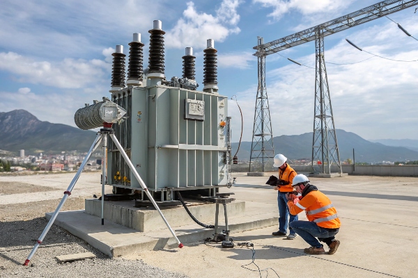
As someone who’s overseen countless transformer installations, I’ve seen firsthand how environmental factors can make or break a project. Let’s dive into these critical requirements to ensure your transformer operates safely and efficiently for years to come.
Indoor vs Outdoor Installation: How Climate Impacts Transformer Lifespan?
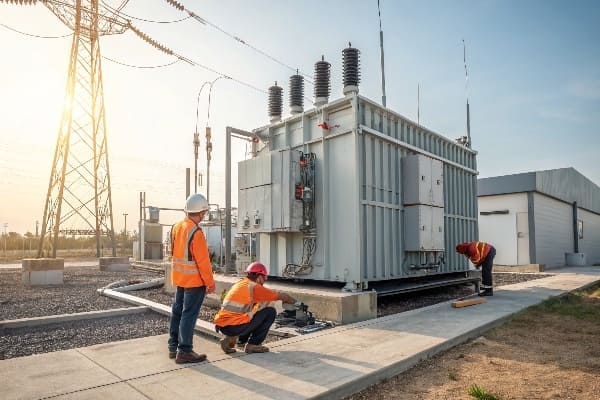
Are you torn between indoor and outdoor transformer installation? The choice isn’t just about space – it can significantly affect your transformer’s lifespan and performance.
Climate plays a crucial role in transformer lifespan. Indoor installations offer protection from extreme weather but may require additional cooling. Outdoor installations face challenges like temperature fluctuations, humidity, and pollution. The choice impacts maintenance needs, efficiency, and overall lifespan.
In my years of experience, I’ve seen how climate can dramatically impact transformer performance. Let’s break down the key differences:
Indoor Installation
-
Advantages:
- Protection from harsh weather conditions
- Controlled environment for optimal performance
- Easier maintenance access
-
Challenges:
- May require additional cooling systems
- Space constraints in some facilities
- Potential for higher installation costs
Outdoor Installation
-
Advantages:
- No building space required
- Natural cooling can be more efficient
- Easier to accommodate larger transformers
-
Challenges:
- Exposure to weather extremes
- Higher risk of corrosion and contamination
- May require additional protective enclosures
Climate Impact Comparison
| Climate Factor | Indoor Impact | Outdoor Impact |
|---|---|---|
| Temperature | Controlled, may need cooling | Fluctuations affect efficiency |
| Humidity | Can be controlled | Risk of moisture ingress |
| Pollution | Minimal exposure | Direct exposure, more maintenance |
| UV Radiation | No impact | Can degrade external components |
I once worked on a project in a coastal area where the client insisted on outdoor installation to save on building costs. Within two years, the transformer suffered significant corrosion due to salt air exposure. We ended up retrofitting an enclosure, which cost more than an initial indoor installation would have.
Lifespan Considerations
-
Temperature Cycling:
- Outdoor transformers face more extreme temperature changes
- Can lead to faster insulation degradation
-
Moisture Exposure:
- Indoor installations have better moisture control
- Outdoor units need robust sealing and breathers
-
Maintenance Frequency:
- Outdoor units typically require more frequent inspections
- Indoor units benefit from a controlled environment
Decision Factors
-
Location Climate:
- Extreme temperatures favor indoor installation
- Moderate climates may allow for outdoor placement
-
Space Availability:
- Limited indoor space may necessitate outdoor installation
- Consider future expansion needs
-
Load Profile:
- High-load transformers may benefit from outdoor natural cooling
- Critical loads might prefer indoor installation for added protection
-
Budget Considerations:
- Initial costs vs. long-term maintenance expenses
- Factor in potential lifespan differences
Remember, the choice between indoor and outdoor installation isn’t just about current conditions. Consider future climate projections, especially with the increasing frequency of extreme weather events. A well-planned installation today can save you from costly relocations or retrofits in the future.
Foundation Design: 5 Ground Preparation Rules to Prevent Subsidence?
Are you confident your transformer’s foundation can withstand the test of time? Many overlook this critical aspect, leading to costly and dangerous subsidence issues.
Proper foundation design is crucial for transformer stability and longevity. Key rules include soil analysis, load calculation, drainage planning, reinforcement design, and seismic considerations. Following these rules prevents subsidence and ensures long-term transformer safety and performance.

Throughout my career, I’ve seen how a well-designed foundation can make or break a transformer installation. Let’s dive into the five essential rules for ground preparation:
Rule 1: Conduct Thorough Soil Analysis
-
Importance:
- Determines soil bearing capacity
- Identifies potential issues like expansive soils or high water tables
-
Methods:
- Geotechnical surveys
- Soil borings and sample testing
-
Key Factors:
- Soil type and composition
- Moisture content and drainage characteristics
Rule 2: Calculate Total Load Accurately
-
Components to Consider:
- Transformer weight (including oil)
- Accessory equipment weight
- Dynamic loads during operation
-
Safety Factors:
- Apply appropriate safety margins
- Account for potential future upgrades
-
Load Distribution:
- Design for even load distribution
- Consider pad size and thickness
Rule 3: Plan for Proper Drainage
-
Importance:
- Prevents water accumulation
- Reduces risk of soil erosion and foundation damage
-
Design Elements:
- Sloped surfaces for water runoff
- Adequate drainage systems around the foundation
-
Material Selection:
- Use of permeable materials where appropriate
- Waterproofing measures for concrete foundations
Rule 4: Implement Robust Reinforcement
-
Reinforcement Types:
- Steel rebar for concrete foundations
- Fiber reinforcement for additional strength
-
Design Considerations:
- Rebar spacing and size based on load calculations
- Proper concrete mix design for durability
-
Quality Control:
- Ensure proper placement and coverage of reinforcement
- Regular inspections during construction
Rule 5: Account for Seismic Activity
-
Seismic Zone Assessment:
- Determine local seismic risk
- Apply appropriate design standards (e.g., IEEE 693)
-
Design Features:
- Use of base isolation systems in high-risk areas
- Incorporation of flexible connections
-
Testing and Certification:
- Conduct seismic qualification tests where required
- Obtain necessary certifications for compliance
Foundation Design Comparison
| Design Aspect | Basic Design | Advanced Design |
|---|---|---|
| Soil Analysis | Standard tests | Comprehensive geotechnical survey |
| Load Calculation | Static load only | Static and dynamic load analysis |
| Drainage | Simple slope | Integrated drainage system |
| Reinforcement | Standard rebar | Advanced materials and design |
| Seismic Design | Basic compliance | Full seismic isolation |
I once worked on a project where the client opted for a basic foundation design to save costs. Within a year, we noticed significant settling, threatening the transformer’s stability. The cost of rectifying the foundation far exceeded what a proper initial design would have cost.
Additional Considerations
-
Environmental Factors:
- Consider freeze-thaw cycles in cold climates
- Account for potential chemical exposure in industrial areas
-
Future Expansion:
- Design foundations with potential upgrades in mind
- Allow for additional equipment or increased capacity
-
Maintenance Access:
- Ensure foundation design allows for easy maintenance access
- Consider oil containment requirements in the design
-
Local Regulations:
- Comply with local building codes and standards
- Obtain necessary permits and approvals
Remember, a well-designed foundation is an investment in your transformer’s future. While it may seem tempting to cut costs here, the long-term benefits of a robust foundation far outweigh the initial savings of a basic design. Always consult with experienced engineers and geotechnical experts to ensure your foundation meets all necessary requirements for your specific site and transformer.
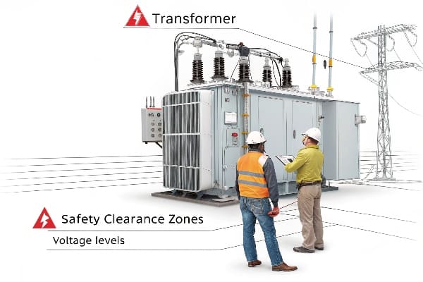
Clearance Zone Calculator: Minimum Safe Distances for Different Voltages?
Are you confident about the safety clearances around your transformer? Misjudging these distances can lead to catastrophic accidents and costly compliance issues.
Proper clearance zones are critical for transformer safety. Minimum safe distances vary based on voltage levels, ranging from a few feet for low voltage to several meters for high voltage installations. Accurate calculation and implementation of these zones are essential for personnel safety and regulatory compliance.
In my years of experience, I’ve seen how crucial proper clearance zones are for both safety and operational efficiency. Let’s break down the key factors and provide a practical calculator for different voltage levels:
Factors Influencing Clearance Zones
-
Voltage Level:
- Higher voltages require larger clearances
- Primary factor in determining safe distances
-
Insulation Type:
- Air insulation vs. solid/liquid insulation
- Affects the required clearance distance
-
Environmental Conditions:
- Altitude can affect air insulation properties
- Humidity and pollution levels may require adjustments
-
Accessibility:
- Public vs. restricted access areas
- Different standards may apply based on who can access the area
Clearance Zone Calculator
Here’s a simplified calculator for common voltage levels (based on IEEE standards):
| Voltage Level | Minimum Clearance (Feet) | Minimum Clearance (Meters) |
|---|---|---|
| 480 V | 3 ft | 0.9 m |
| 4.16 kV | 4 ft | 1.2 m |
| 13.8 kV | 5 ft | 1.5 m |
| 34.5 kV | 6 ft | 1.8 m |
| 69 kV | 7 ft | 2.1 m |
| 138 kV | 10 ft | 3.0 m |
| 230 kV | 15 ft | 4.6 m |
| 500 kV | 25 ft | 7.6 m |
Note: These are general guidelines. Always consult local regulations and specific standards for your installation.
I once consulted on a project where the clearance zones were underestimated for a 138 kV transformer. During a maintenance operation, a worker came dangerously close to the live parts. This near-miss led to a complete redesign of the substation layout, costing significant time and resources.
Implementing Safe Clearance Zones
-
Physical Barriers:
- Use fences, walls, or enclosures to restrict access
- Ensure barriers meet height and strength requirements
-
Warning Signs:
- Clear, visible signage indicating danger zones
- Use multiple languages if necessary
-
Ground Markings:
- Paint or mark safe boundaries on the ground
- Use contrasting colors for visibility
-
Interlocks and Sensors:
- Install electronic access control systems
- Use motion sensors to detect unauthorized entry
Additional Safety Considerations
-
Working Clearances:
- Allow extra space for maintenance activities
- Consider equipment movement and replacement needs
-
Emergency Access:
- Ensure clear paths for emergency responders
- Design for quick evacuation if necessary
-
Vegetation Management:
- Maintain clear zones free from vegetation growth
- Regular trimming and inspection of surrounding areas
-
Future Expansion:
- Plan clearance zones with potential upgrades in mind
- Allow extra space if higher voltage equipment might be installed later
Remember, while these guidelines provide a good starting point, every installation is unique. Factors like specific equipment design, local regulations, and site conditions can all impact the required clearance zones. Always consult with safety experts and refer to the latest standards when planning your transformer installation.
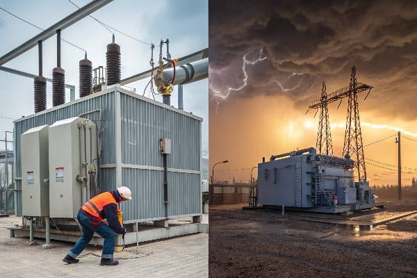
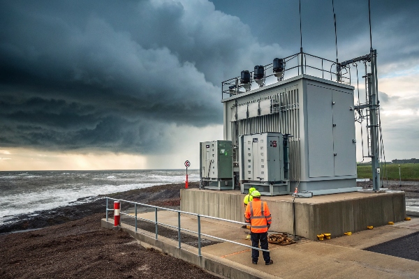
Flood Risk Mitigation: Waterproofing Strategies for Coastal Installations?
Are you worried about your coastal transformer installation being one storm away from disaster? You’re right to be concerned. Flood damage can lead to catastrophic failures and environmental hazards.
Effective flood risk mitigation for coastal transformer installations involves elevated foundations, waterproof enclosures, robust drainage systems, and emergency shutdown procedures. These strategies protect against water ingress, corrosion, and electrical failures in flood-prone areas.
Having worked on numerous coastal installations, I’ve seen firsthand the devastating effects of inadequate flood protection. Let’s explore key strategies to keep your transformers high and dry:
Elevation: Raising the Bar
-
Foundation Height:
- Elevate transformer pad above historical flood levels
- Add extra height for future sea level rise projections
-
Equipment Placement:
- Install critical components above potential flood lines
- Use raised platforms for control cabinets and accessories
-
Access Considerations:
- Design elevated walkways for maintenance access
- Ensure emergency access routes remain above water
Waterproofing: Sealing the Deal
-
Transformer Tank:
- Use corrosion-resistant materials for coastal environments
- Apply specialized marine-grade coatings
-
Sealing Techniques:
- Implement watertight seals on all openings
- Use submersible-grade gaskets and O-rings
-
Cable Entries:
- Install waterproof cable glands
- Use conduit sealing systems to prevent water ingress
Drainage Systems: Managing the Flow
| Component | Function | Design Consideration |
|---|---|---|
| Sump Pumps | Remove accumulated water | Redundant systems, backup power |
| Perimeter Drains | Divert water away from installation | Proper sizing for heavy rainfall |
| Oil-Water Separators | Prevent oil contamination | Comply with environmental regulations |
Emergency Procedures: Preparing for the Worst
-
Flood Detection:
- Install water level sensors
- Implement early warning systems
-
Shutdown Protocols:
- Develop clear procedures for emergency de-energization
- Train personnel on rapid response actions
-
Recovery Plans:
- Create detailed post-flood inspection checklists
- Establish procedures for safe re-energization
I once worked on a substation retrofit in a hurricane-prone area. Despite initial skepticism about the cost, we implemented comprehensive flood protection measures. When a major storm hit the following year, our installation was one of the few that remained operational, proving the value of thorough flood mitigation strategies.
Advanced Protection Measures
-
Flood Barriers:
- Deployable flood barriers for temporary protection
- Permanent flood walls for high-risk areas
-
Smart Monitoring:
- Real-time monitoring of water levels and weather conditions
- Integration with SCADA systems for remote management
-
Buoyant Design:
- For extreme cases, design transformer installations to float
- Requires specialized tethering and flexible connections
Environmental Considerations
-
Oil Containment:
- Design oil containment systems to withstand flooding
- Implement secondary containment measures
-
Saltwater Corrosion:
- Use materials resistant to saltwater corrosion
- Implement regular inspection and maintenance programs
-
Ecosystem Impact:
- Consider local ecosystem in drainage design
- Implement measures to prevent oil spills during floods
Remember, effective flood risk mitigation is not just about protecting equipment – it’s about ensuring continuity of power supply and preventing environmental disasters. While these measures may seem costly upfront, they pale in comparison to the potential losses from flood damage. Always consult with coastal engineering experts and stay updated on the latest flood prediction models for your area.
Vibration Control: Anti-Seismic Requirements in Earthquake Zones?
Are you confident your transformer can withstand the next big shake? In earthquake-prone areas, vibration control isn’t just about performance – it’s about preventing catastrophic failures.
Anti-seismic requirements for transformers in earthquake zones include base isolation systems, reinforced foundations, flexible connections, and seismic qualification testing. These measures ensure transformer stability, prevent oil leaks, and maintain electrical connections during seismic events.
Having worked on transformer installations in some of the world’s most seismically active regions, I’ve learned that proper vibration control is non-negotiable. Let’s explore the key anti-seismic requirements:
Base Isolation Systems: The Foundation of Stability
-
Types of Isolators:
- Elastomeric bearings
- Friction pendulum bearings
- Spring-damper systems
-
Function:
- Absorb and dissipate seismic energy
- Reduce transmission of ground motion to the transformer
-
Design Considerations:
- Natural frequency of the isolation system
- Maximum displacement capacity
- Durability and maintenance requirements
Reinforced Foundations
-
Enhanced Concrete Design:
- Higher strength concrete mixes
- Increased reinforcement ratios
-
Anchor Bolt Systems:
- Oversized and deep-set anchor bolts
- Use of expansion or chemical anchors for retrofit applications
-
Soil-Structure Interaction:
- Consider soil amplification effects
- Implement soil improvement techniques if necessary
Flexible Connections: Allowing for Movement
-
Bushing Design:
- Use of slip-fit bushings
- Incorporation of flexible gaskets
-
Cable Connections:
- Implement loop or slack in cables
- Use flexible conduit systems
-
Oil Preservation Systems:
- Flexible piping for oil circulation systems
- Expansion joints in radiator connections
Seismic Qualification Testing
| Test Type | Purpose | Standard |
|---|---|---|
| Shake Table Tests | Simulate real earthquake conditions | IEEE 693 |
| Finite Element Analysis | Model transformer behavior under seismic loads | ASCE 7 |
| Time History Analysis | Evaluate response to specific earthquake records | IEC 60068-3-3 |
I once worked on a transformer installation in Japan where we implemented a state-of-the-art base isolation system. During a significant earthquake, while nearby structures suffered damage, our transformer remained fully operational. This experience underscored the critical importance of thorough seismic protection measures.
Additional Anti-Seismic Measures
-
Internal Bracing:
- Reinforce core and coil assemblies
- Add additional support for tap changers and other internal components
-
Tank Design:
- Use of stiffeners to prevent tank deformation
- Implement pressure relief systems to prevent rupture
-
Monitoring Systems:
- Install seismic sensors for real-time monitoring
- Implement automatic shutdown systems for severe events
Regulatory Compliance and Standards
-
IEEE 693: Recommended Practice for Seismic Design of Substations
- Provides guidelines for seismic qualification of electrical equipment
- Defines performance levels and testing procedures
-
IEC 60068-3-3: Environmental Testing – Seismic Test Methods for Equipment
- Outlines test methods for evaluating equipment under seismic conditions
- Applicable to international installations
-
Local Building Codes:
- Comply with region-specific seismic design requirements
- Often based on local seismic hazard maps
Remember, seismic protection is not a one-size-fits-all solution. The specific measures required will depend on factors like local seismic activity, soil conditions, and the criticality of the installation. Always consult with seismic engineering experts and stay updated on the latest standards and technologies in this rapidly evolving field.
Thermal Management Masterclass: Ambient Temperature Limits by Transformer Type?
Are you struggling to keep your transformers cool under pressure? You’re not alone. Proper thermal management is crucial for transformer efficiency and longevity, but it’s often misunderstood.
Effective thermal management is critical for transformer performance and lifespan. Ambient temperature limits vary by transformer type, with dry-type transformers typically tolerating higher temperatures than oil-filled ones. Proper cooling systems and temperature monitoring are essential for maintaining optimal operating conditions.

Throughout my career, I’ve seen how crucial proper thermal management is for transformer performance. Let’s dive into the specifics for different transformer types:
Oil-Filled Transformers
-
Ambient Temperature Limits:
- Standard range: -25°C to 40°C (-13°F to 104°F)
- Extended range models available for extreme climates
-
Cooling Methods:
- ONAN (Oil Natural Air Natural)
- ONAF (Oil Natural Air Forced)
- OFAF (Oil Forced Air Forced)
- ODAF (Oil Directed Air Forced)
-
Temperature Monitoring:
- Top oil temperature
- Winding hot spot temperature
Dry-Type Transformers
-
Ambient Temperature Limits:
- Standard range: -25°C to 50°C (-13°F to 122°F)
- Some models rated for up to 60°C (140°F)
-
Cooling Methods:
- AN (Air Natural)
- AF (Air Forced)
-
Temperature Monitoring:
- Winding temperature
- Core temperature
Comparison of Temperature Limits
| Transformer Type | Standard Max Ambient | Extended Range |
|---|---|---|
| Oil-Filled | 40°C (104°F) | Up to 55°C (131°F) |
| Dry-Type | 50°C (122°F) | Up to 60°C (140°F) |
I once consulted on a project in the Middle East where ambient temperatures regularly exceeded 50°C (122°F). We had to implement a custom cooling solution for the oil-filled transformers, including advanced radiator designs and forced oil circulation. This experience taught me the importance of considering extreme environmental conditions in transformer design and selection.
Thermal Management Strategies
-
Ventilation and Air Flow:
- Proper spacing between transformers
- Adequate air circulation in indoor installations
-
Cooling System Design:
- Sizing radiators and fans appropriately
- Implementing temperature-controlled cooling activation
-
Insulation Systems:
- Using high-temperature insulation materials
- Implementing thermal barriers in critical areas
-
Load Management:
- Implementing dynamic loading based on ambient temperature
- Using online monitoring systems for real-time load adjustment
Advanced Cooling Technologies
-
Phase Change Materials:
- Absorb excess heat during peak loads
- Release heat during cooler periods
-
Heat Pipe Technology:
- Efficient heat transfer without moving parts
- Applicable to both oil-filled and dry-type transformers
-
Synthetic Ester Fluids:
- Higher flash and fire points than mineral oil
- Allow for higher operating temperatures
Remember, effective thermal management is not just about meeting minimum standards – it’s about optimizing performance and extending transformer life. Always consider the specific environmental conditions of your installation site and consult with thermal management experts to design the most effective cooling solution for your transformers.
EMI Shielding Essentials: Protecting Transformers in High-RF Environments?
Are you concerned about electromagnetic interference (EMI) affecting your transformer’s performance? In today’s high-tech world, EMI shielding is more crucial than ever, especially in RF-dense environments.
EMI shielding is essential for protecting transformers in high-RF environments. Effective shielding techniques include Faraday cages, conductive enclosures, and proper grounding. These measures prevent electromagnetic interference from affecting transformer performance and protect sensitive equipment from transformer-generated EMI.
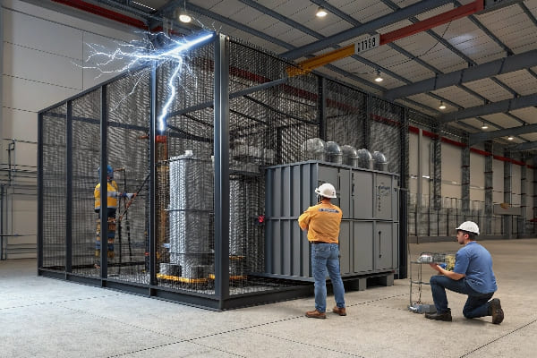
In my years of working with transformers in various environments, I’ve seen firsthand how critical proper EMI shielding can be. Let’s explore the essentials of EMI protection:
Understanding EMI Sources and Effects
-
External EMI Sources:
- Radio and TV transmitters
- Cellular base stations
- Industrial equipment
-
Transformer-Generated EMI:
- Core magnetostriction
- Winding vibrations
- Partial discharges
-
Effects of EMI:
- Voltage distortions
- Operational errors in control systems
- Interference with nearby sensitive equipment
EMI Shielding Techniques
| Technique | Description | Effectiveness |
|---|---|---|
| Faraday Cage | Conductive enclosure surrounding the transformer | High |
| Conductive Paints | Applied to transformer tank and components | Moderate |
| Metallic Foils | Wrapped around cables and sensitive parts | Moderate to High |
| Ferrite Beads | Used on cables to suppress high-frequency noise | Moderate |
I once worked on a project near a powerful radio transmitter. Initially, we experienced unexplained voltage fluctuations and control system errors. After implementing a comprehensive EMI shielding solution, including a custom-designed Faraday cage, the issues were completely resolved.
Key Components of EMI Shielding
-
Enclosure Design:
- Use of conductive materials (e.g., steel, aluminum)
- Proper sealing of all openings and joints
-
Cable Shielding:
- Use of shielded cables for all connections
- Proper termination of cable shields
-
Grounding System:
- Low-impedance grounding network
- Bonding of all metallic components
-
Filtering:
- EMI filters on power and control cables
- Surge protection devices
Special Considerations for High-RF Environments
-
Frequency Analysis:
- Identify specific frequencies of concern
- Tailor shielding solutions to target frequencies
-
Multi-Layer Shielding:
- Combine different materials for broadband protection
- Use of composite materials with specific shielding properties
-
Active Cancellation Systems:
- For extreme cases, implement active EMI cancellation
- Requires sophisticated sensing and signal processing
Testing and Verification
-
EMC Testing:
- Conduct electromagnetic compatibility tests
- Verify compliance with relevant standards (e.g., IEC 61000)
-
On-Site Measurements:
- Perform field strength measurements before and after shielding
- Use spectrum analyzers to identify specific interference sources
-
Continuous Monitoring:
- Implement EMI monitoring systems for long-term performance tracking
- Set up alerts for unexpected EMI levels
Remember, effective EMI shielding is not just about protecting the transformer – it’s about ensuring the reliability and performance of the entire electrical system. In high-RF environments, a comprehensive approach to EMI mitigation is essential. Always consult with EMC experts and stay updated on the latest shielding technologies and standards.
Conclusion
Proper power transformer installation requires careful consideration of environmental factors. From climate impacts to seismic protection, thermal management to EMI shielding, each aspect plays a crucial role in ensuring safe, efficient, and long-lasting transformer operation. Always consult experts and adhere to latest standards for optimal results.
