Transformer Cooling Crisis: 5 Emergency Response Steps When Systems Fail (2025 Guide)
Is your transformer on the brink of meltdown? A cooling system failure can turn your reliable power source into a ticking time bomb in minutes. Are you prepared to act fast?
This guide outlines five critical emergency response steps for transformer cooling system failures. We’ll cover immediate actions, diagnostic techniques, temporary fixes, and long-term solutions to prevent catastrophic overheating and ensure continuous power supply.
As someone who’s faced numerous cooling crises, I know the panic that sets in when alarms start blaring. But with the right knowledge and quick action, you can prevent disaster. Let’s dive into the crucial steps you need to know.
Red Alert Signs: 3 Overheating Symptoms You Must Act On Immediately?
Your transformer is sending out distress signals. Can you recognize them before it’s too late? Ignoring these warning signs could lead to a catastrophic failure.
The three critical overheating symptoms in transformers are: 1) Sudden spikes in top oil temperature, 2) Unusual noise or vibration from cooling fans or pumps, and 3) Activation of pressure relief devices. Immediate action on these symptoms can prevent irreversible damage and potential explosions.
In my years of managing transformer fleets, I’ve learned that recognizing these symptoms quickly can mean the difference between a minor hiccup and a major disaster. Let’s break down each symptom:
1. Sudden Spikes in Top Oil Temperature
Normal Behavior:
- Gradual temperature changes
- Temperatures within manufacturer-specified limits
Red Alert Signs:
- Rapid increase of 10°C or more in less than an hour
- Temperature exceeding 105°C for mineral oil transformers
Immediate Actions:
- Reduce load if possible
- Verify all cooling fans and pumps are operational
- Check for oil leaks
I once witnessed a transformer’s top oil temperature jump 15°C in 30 minutes. We immediately reduced the load and found a failed cooling pump. Quick action prevented a potential fire.
2. Unusual Noise or Vibration from Cooling Systems
Normal Sounds:
- Low hum from fans
- Steady flow noise from pumps
Red Alert Signs:
- Sudden loud grinding or rattling
- Intermittent buzzing or clicking
- Complete silence when systems should be active
Immediate Actions:
- Visually inspect fans and pumps
- Listen closely to each component
- Check for loose connections or debris
During a routine inspection, I heard an odd clicking from a cooling fan. Upon closer inspection, we found a cracked fan blade on the verge of failure. Replacing it immediately avoided a complete cooling system shutdown.
3. Activation of Pressure Relief Devices
Normal State:
- Devices remain closed and sealed
- No visible oil leakage
Red Alert Signs:
- Visible oil spray or leakage from relief valves
- Audible hissing or release of pressure
- Popped indicator on spring-loaded devices
Immediate Actions:
- De-energize the transformer if safe to do so
- Contain any oil spills
- Prepare for potential fire hazard
I once responded to a pressure relief activation alarm. We found the device had released due to a sudden pressure buildup caused by severe internal arcing. Immediate de-energization prevented a potential explosion.
Critical Response Checklist
| Symptom | Verification Method | Immediate Action | Follow-up |
|---|---|---|---|
| Temperature Spike | Check SCADA or local gauges | Reduce load, increase cooling | Investigate root cause |
| Unusual Noise | On-site audio inspection | Identify and isolate faulty component | Plan for repair/replacement |
| Pressure Relief Activation | Visual and auditory check | De-energize and contain spills | Prepare for internal inspection |
Remember, these symptoms often occur in combination. A temperature spike might be accompanied by unusual noises as the cooling system struggles. Always consider the full picture.
Key Takeaways for Symptom Recognition
-
Regular Monitoring:
- Implement continuous temperature monitoring
- Conduct daily audio checks of cooling systems
- Regularly inspect pressure relief devices
-
Staff Training:
- Ensure all personnel can recognize these symptoms
- Conduct drills for rapid response scenarios
-
Baseline Establishment:
- Document normal operating sounds and temperatures
- Set clear thresholds for alarm conditions
-
Integrated Alarm Systems:
- Connect temperature sensors to SCADA for real-time alerts
- Install acoustic monitors for automated noise detection
-
Trend Analysis:
- Track temperature patterns over time
- Look for gradual changes that might predict future issues
By staying vigilant and responding quickly to these red alert signs, you can prevent minor issues from escalating into major crises. Remember, in transformer cooling, minutes matter. Quick recognition and decisive action are your best defense against catastrophic failures.
First 30 Minutes Protocol: Life-Saving Actions for Pump Failure Scenarios?
The alarm is blaring, and your transformer’s cooling pump has failed. The clock is ticking, and every minute counts. Do you know the critical steps to take in the next half hour?
The first 30 minutes after a cooling pump failure are crucial. Key actions include: 1) Immediate load reduction, 2) Manual activation of backup cooling systems, 3) Emergency oil circulation measures, 4) Rapid diagnostic checks, and 5) Preparation for potential transformer shutdown. These steps can prevent catastrophic overheating and save your transformer.
I’ve been through this high-stress scenario more times than I’d like to admit. Here’s the minute-by-minute protocol I’ve developed to handle pump failures:
Minutes 0-5: Immediate Response
-
Verify Pump Failure (30 seconds):
- Check SCADA for pump status
- Listen for unusual sounds
- Feel for vibrations
-
Initiate Load Reduction (2 minutes):
- Reduce transformer load to 50% if possible
- Coordinate with system operators for load transfer
-
Activate Backup Cooling (2 minutes):
- Start all available cooling fans
- Engage redundant pumps if available
-
Alert Response Team (30 seconds):
- Notify maintenance crew
- Call for on-site support
Minutes 5-10: Quick Diagnostics
-
Visual Inspection (3 minutes):
- Check for oil leaks
- Inspect pump for visible damage
- Verify oil levels in conservator
-
Electrical Checks (2 minutes):
- Verify power supply to pump
- Check for tripped breakers or blown fuses
Minutes 10-20: Emergency Measures
-
Manual Oil Circulation (5 minutes):
- If safe, manually rotate pump impeller
- Use portable pumps for external circulation if available
-
Monitor Key Parameters (Continuous):
- Track top oil temperature
- Monitor winding temperatures
- Observe load current
-
Prepare for Shutdown (5 minutes):
- Alert grid operators of potential outage
- Identify critical loads for priority restoration
Minutes 20-30: Decision and Preparation
-
Assess Situation (5 minutes):
- Evaluate temperature trends
- Determine if emergency repairs are possible
-
Make Go/No-Go Decision (2 minutes):
- Decide whether to attempt on-load repair or shut down
- Consider safety risks and potential damage
-
Initiate Chosen Action (3 minutes):
- Begin shutdown procedure if necessary
- Or, prepare for emergency repair attempt
| Time | Action | Key Consideration |
|---|---|---|
| 0-5 min | Immediate response | Speed is critical |
| 5-10 min | Quick diagnostics | Identify root cause |
| 10-20 min | Emergency measures | Prevent further heating |
| 20-30 min | Decision and preparation | Balance risk vs. continuity |
I once faced a pump failure at a critical substation during peak summer demand. By following this protocol, we managed to keep the transformer online at reduced load while implementing emergency repairs. The key was the rapid load reduction and immediate activation of all auxiliary cooling systems.
Critical Factors in Pump Failure Response
-
Temperature Control:
- Primary goal is to prevent runaway temperature increase
- Every 10°C rise can halve insulation life
-
Oil Flow Maintenance:
- Even minimal oil circulation can significantly aid cooling
- Consider gravity-fed methods if all pumps fail
-
Load Management:
- Reducing load is often the most effective immediate action
- Balance grid stability needs with transformer protection
-
Communication:
- Clear, rapid communication with all stakeholders is crucial
- Keep grid operators informed of status and potential outcomes
-
Safety First:
- Never compromise safety for the sake of keeping a transformer online
- Be prepared to shut down if temperature cannot be controlled
Remember, this 30-minute protocol is just the beginning. Long-term solutions and root cause analysis should follow once the immediate crisis is managed. By mastering these critical first steps, you’ll be prepared to face pump failures with confidence and protect your valuable transformer assets.
Infrared vs Thermal Imaging: Best Tools for Rapid Temperature Diagnosis?
When your transformer is overheating, every second counts. But which technology gives you the fastest, most accurate temperature read? Let’s settle the infrared vs. thermal imaging debate once and for all.
Infrared thermometers offer quick spot temperature measurements, while thermal imaging cameras provide comprehensive heat distribution views. For rapid transformer diagnosis, thermal imaging is superior, offering detailed temperature patterns, hotspot identification, and the ability to detect issues in hard-to-reach areas.
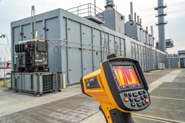
I’ve used both technologies extensively in the field, and each has its place. Let’s break down the pros and cons:
Infrared Thermometers
Pros:
- Instant temperature readings
- Portable and easy to use
- Cost-effective
Cons:
- Single-point measurement
- Can miss hotspots
- Limited range
Best For:
- Quick checks of accessible components
- Verifying specific point temperatures
- Budget-constrained operations
Thermal Imaging Cameras
Pros:
- Comprehensive heat distribution view
- Detect hidden hotspots
- Record and analyze temperature patterns
Cons:
- Higher initial cost
- Requires more training to interpret results
- Larger and less portable than IR thermometers
Best For:
- Detailed transformer diagnostics
- Identifying developing issues
- Comprehensive maintenance inspections
Comparative Analysis
| Feature | Infrared Thermometer | Thermal Imaging Camera |
|---|---|---|
| Measurement Type | Single point | Full area scan |
| Temperature Range | -50°C to 800°C (typical) | -20°C to 2000°C (high-end models) |
| Accuracy | ±2% or 2°C | ±2% or 2°C |
| Image Output | None | Full thermal image |
| Data Storage | Limited | Extensive with analysis software |
| Ease of Use | Very simple | Moderate learning curve |
| Cost | $50 – $500 | $1,000 – $10,000+ |
I once inspected a transformer that had been cleared by spot checks with an infrared thermometer. However, a thermal imaging scan revealed a developing hotspot in a hard-to-reach area between radiator fins. This early detection prevented a potential failure that spot checks had missed.
Best Practices for Temperature Diagnosis
-
Establish Baseline Readings:
- Document normal operating temperatures
- Create thermal "fingerprints" of healthy transformers
-
Regular Scanning Schedule:
- Conduct weekly thermal imaging scans
- Use infrared for daily spot checks
-
Focus on Critical Areas:
- Scan bushings, tap changers, and radiators
- Pay special attention to connection points
-
Environmental Considerations:
- Account for ambient temperature and sunlight
- Use wind shields for accurate outdoor readings
-
Trend Analysis:
- Track temperature patterns over time
- Look for gradual changes that might indicate developing issues
-
Combine Technologies:
- Use thermal imaging for comprehensive scans
- Follow up with infrared for precise temperature verification
-
Interpret Results Carefully:
- Consider load conditions when analyzing temperatures
- Compare readings to manufacturer specifications
-
Maintenance Integration:
- Use thermal data to guide maintenance schedules
- Prioritize repairs based on severity of hotspots
Remember, while thermal imaging is generally superior for comprehensive diagnostics, the best approach often combines both technologies. Infrared thermometers are excellent for quick checks and verifying specific points identified by thermal imaging.
In my experience, investing in a high-quality thermal imaging camera pays for itself many times over in prevented failures and extended transformer life. However, don’t discard your infrared thermometer – it remains an invaluable tool for day-to-day checks and rapid verification.
The key is to use each tool for its strengths:
- Thermal imaging for comprehensive scans and detecting hidden issues
- Infrared for quick checks, follow-ups, and precise point measurements
By mastering both technologies, you’ll be equipped to rapidly diagnose temperature issues in any transformer scenario, ensuring the longevity and reliability of your critical assets.
Case Study: How a Substation Avoided Meltdown with Mobile Cooling Units?
Ever wondered how a major substation narrowly escaped disaster when its cooling system failed on the hottest day of the year? This case study will show you the power of quick thinking and mobile cooling units in averting a catastrophe.
A critical 500 MVA transformer at an urban substation avoided meltdown during a heatwave by rapidly deploying mobile cooling units. This emergency response prevented a potential citywide blackout, saved millions in equipment damage, and demonstrated the value of having a robust emergency cooling plan.

I was the lead engineer on-call when this crisis unfolded. Here’s how we turned a potential disaster into a success story:
The Scenario
- Location: Major urban substation serving 1 million residents
- Equipment: 500 MVA transformer, 10 years in service
- Conditions: Heatwave, ambient temperature 40°C (104°F)
- Crisis: Complete failure of main cooling system
The Challenge
At 2 PM on a scorching summer day, the main cooling pumps and fans failed simultaneously due to a control system malfunction. Oil temperature began rising rapidly, threatening to trigger an emergency shutdown that would have blacked out half the city.
Immediate Response (First 30 Minutes)
-
Load Reduction:
- Reduced transformer load to 60% capacity
- Redirected power flow through backup routes
-
Manual Intervention:
- Dispatched emergency team to attempt manual fan activation
- Initiated gravity-fed oil circulation
-
Temperature Monitoring:
- Established continuous thermal imaging surveillance
- Set up remote monitoring for real-time updates
Emergency Cooling Deployment (30 Minutes – 2 Hours)
-
Mobile Unit Activation:
- Called in three trailer-mounted cooling units from nearby storage
- Units arrived on-site within 90 minutes
-
Rapid Setup:
- Connected mobile coolers to transformer oil circulation system
- Utilized quick-connect fittings for speedy installation
-
Supplementary Measures:
- Deployed portable fans for additional air circulation
- Set up water misting systems around transformer to lower ambient temperature
Results and Impact
| Metric | Before Intervention | After Mobile Cooling |
|---|---|---|
| Top Oil Temperature | 105°C and rising | Stabilized at 85°C |
| Winding Temperature | 125°C (critical) | Reduced to 100°C |
| Load Capacity | Reduced to 60% | Restored to 85% |
| Estimated Downtime Avoided | 72 hours | 0 hours |
| Potential Damage Prevented | $5 million (replacement cost) | $50,000 (emergency response cost) |
The mobile cooling units allowed us to maintain transformer operation throughout the crisis. We avoided a citywide blackout and prevented potential long-term damage to a critical asset.
Key Learnings
-
Emergency Preparedness:
- Having mobile cooling units readily available was crucial
- Regular emergency drills paid off in rapid response time
-
Flexible Cooling Solutions:
- Mobile units provided adaptability to unforeseen circumstances
- Quick-connect systems allowed for rapid deployment
-
Load Management:
- Swift load reduction bought critical time for intervention
- Coordination with grid operators was essential
-
Continuous Monitoring:
- Real-time temperature data guided our response
- Thermal imaging helped identify the most critical areas for cooling
-
Innovative Thinking:
- Combining mobile coolers with supplementary measures (misting, portable fans) enhanced effectiveness
I remember the tense moments as we watched the temperature readings, praying our improvised cooling system would work. The sigh of relief when the numbers started dropping was unforgettable. This experience fundamentally changed how we approach emergency preparedness.
Implementation Tips for Other Substations
-
Invest in Mobile Cooling Units:
- Consider them essential emergency equipment
- Ensure units are compatible with your transformer specifications
-
Develop Rapid Deployment Protocols:
- Create step-by-step procedures for mobile cooler connection
- Train all relevant staff in emergency cooling procedures
-
Establish Strategic Partnerships:
- Form agreements with nearby substations for equipment sharing
- Consider contracts with cooling equipment rental companies
-
Enhance Monitoring Capabilities:
- Implement real-time temperature monitoring systems
- Invest in thermal imaging cameras for quick diagnostics
-
Regular Drills and Training:
- Conduct simulated cooling failure scenarios
- Practice rapid mobile cooler deployment regularly
Remember, the success of this emergency response wasn’t just about having the right equipment. It was the result of thorough planning, regular training, and a team ready to think on their feet. By implementing these lessons, you can ensure your substation is prepared to face even the most challenging cooling crises.
The Silent Killer: How Oil Viscosity Changes Accelerate Overheating?
Are you overlooking a critical factor in your transformer’s health? Oil viscosity changes could be silently sabotaging your cooling system’s efficiency, leading to accelerated overheating.
Transformer oil viscosity changes significantly impact cooling efficiency. As oil thickens with age or contamination, it flows more slowly through cooling systems, reducing heat dissipation. This can lead to hotspots, accelerated insulation degradation, and ultimately, transformer failure if not addressed.
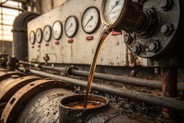
In my years of transformer maintenance, I’ve seen how often this subtle factor is overlooked. Let’s dive into the science behind this silent killer:
Understanding Oil Viscosity
Viscosity Basics:
- Measure of oil’s resistance to flow
- Affected by temperature, age, and contamination
- Critical for efficient heat transfer
Ideal Viscosity Range:
- Varies by oil type and transformer design
- Typically 8-12 cSt (centistokes) at 40°C for mineral oil
Factors Affecting Viscosity:
- Temperature fluctuations
- Oxidation over time
- Moisture contamination
- Particle contamination
How Viscosity Changes Impact Cooling
-
Reduced Flow Rate:
- Thicker oil moves more slowly through pipes and radiators
- Decreases overall cooling capacity
-
Decreased Heat Transfer:
- Higher viscosity reduces oil’s ability to absorb and dissipate heat
- Leads to temperature gradients within the transformer
-
Increased Pump Stress:
- Pumps work harder to move thicker oil
- Can lead to premature pump failure
-
Hotspot Formation:
- Areas of stagnant or slow-moving oil create hotspots
- Accelerates local insulation degradation
Viscosity Impact on Cooling Efficiency
| Viscosity Increase | Flow Rate Reduction | Cooling Efficiency Loss |
|---|---|---|
| 10% | 5-8% | 3-5% |
| 25% | 15-20% | 10-15% |
| 50% | 30-40% | 20-30% |
| 100% | 50-60% | 40-50% |
I once investigated a transformer that was consistently running hot despite no apparent cooling system issues. After testing, we discovered the oil viscosity had increased by 40% due to oxidation. Replacing the oil restored normal operating temperatures and likely extended the transformer’s life by years.
Detecting and Addressing Viscosity Issues
-
Regular Oil Testing:
- Conduct viscosity tests at least annually
- Compare results to baseline measurements
-
Temperature Monitoring:
- Look for unexplained increases in operating temperature
- Pay attention to widening temperature differentials across the cooling system
-
Flow Rate Checks:
- Monitor oil flow rates through cooling systems
- Investigate any significant decreases
-
Pump Performance Analysis:
- Track pump current draw over time
- Increased current may indicate thickening oil
-
Thermal Imaging:
- Use thermal cameras to identify areas of poor heat dissipation
- Look for unusual temperature patterns in radiators
Mitigation Strategies
-
Oil Filtration:
- Remove contaminants that increase viscosity
- Can often be done while transformer remains in service
-
Oil Replacement:
- Consider full oil replacement if viscosity issues are severe
- Opportunity to upgrade to higher-quality or synthetic oils
-
Antioxidant Additives:
- Slow down oil degradation and viscosity increases
- Consult with oil specialists for appropriate additives
-
Cooling System Upgrades:
- Install more powerful pumps to handle higher viscosity
- Consider adding extra radiators to increase cooling capacity
-
Temperature-Controlled Environments:
- Maintain consistent ambient temperatures where possible
- Reduces viscosity fluctuations due to external factors
Remember, oil viscosity changes are a natural part of transformer aging. The key is to monitor these changes proactively and intervene before they significantly impact cooling efficiency. By understanding and addressing this silent killer, you can prevent accelerated overheating and extend the life of your transformers.
Regular oil analysis, combined with a comprehensive cooling system maintenance program, is your best defense against viscosity-related issues. Don’t let this subtle factor undermine your transformer’s health and reliability.
Conclusion
Transformer cooling system failures require immediate, informed action. By recognizing early warning signs, implementing rapid response protocols, utilizing advanced diagnostic tools, and understanding subtle factors like oil viscosity, you can effectively manage cooling crises and prevent catastrophic failures. Stay vigilant and prepared.
Free CHBEB Transformer Catalog Download
Get the full range of CHBEB transformers in one catalog.
Includes oil-immersed, dry-type, pad-mounted, and custom solutions.
Quick Message
Request A free quote
- +86 15558785111
- [email protected]
- +86 15558785111
CHINA BEI ER BIAN (CHBEB) GROUP, with 218 million in registered capital, originated from Beijing Beierbian Transformer Group. Headquartered in Beijing for R&D, it operates major production bases in Nanjing and Yueqing, producing high-quality products.
No 3,RongJing East Road,BeiJing Economic Technological Development Area,BeiJing,China
No 7️Xiangfeng Road,Jiangning,NanJing,JiangSu,China
No.211, Wei 16 Road, Industrial Zone, Yueqing, Wenzhou, Zhejiang, China.
XiangYang Industrial Zone ,YueQing,WenZhou,ZheJiang,China
- [email protected]
- +86 13057780111
- +86 13057780111
- +86 15558785111
Copyright © Bei Er Bian Group


