Are you struggling to navigate the complex world of international transformer diagram standards? You’re not alone. Many engineers and project managers find themselves confused when dealing with IEC and ANSI standards, especially in global projects. But what if you could easily understand and apply these standards to ensure your projects run smoothly across borders?
IEC and ANSI transformer diagram standards differ in symbols, layout conventions, and compliance requirements. IEC is used in Europe and Asia, while ANSI is common in North America. Understanding these differences is essential for global projects, ensuring technical compatibility and smooth cross-border transformer installations.
In this comprehensive guide, I’ll walk you through the key differences between IEC and ANSI standards for transformer diagrams. Whether you’re working on international projects or simply want to expand your knowledge, this article will provide you with the insights you need to navigate these crucial standards effectively.
Why Understanding IEC and ANSI Standards Matters?
Have you ever wondered why there’s so much fuss about diagram standards in transformer projects? The choice between IEC and ANSI standards can significantly impact your project’s success, but why is this understanding so crucial for engineers and project managers?
Understanding IEC and ANSI standards is vital for ensuring technical compatibility, regulatory compliance, and effective communication in global transformer projects. These standards affect diagram interpretation, equipment specifications, and installation procedures. Misalignment between standards can lead to costly errors, project delays, and safety issues, especially in cross-border or export projects.

The Impact of Standards on Transformer Projects
Let’s explore why these standards are so important:
- Technical Compatibility
- Regulatory Compliance
- Project Communication
- Cost Implications
Technical Compatibility
Different standards can lead to significant technical differences:
- Component specifications may vary
- Connection methods might differ
- Safety features could have different requirements
I once worked on a project where an IEC-designed transformer was being installed in an ANSI-standard facility. The mismatch in bushing specifications led to connection issues that required costly on-site modifications.
Regulatory Compliance
Compliance with the correct standard is often a legal requirement:
- Some countries mandate specific standards
- Non-compliance can result in project rejection or legal issues
- Certification processes differ between IEC and ANSI
During a recent export project to the US, we had to completely redraw our diagrams to ANSI standards to meet local regulatory requirements. This unexpected step added weeks to our project timeline.
Project Communication
Standards affect how information is conveyed and understood:
- Symbol differences can lead to misinterpretation
- Layout conventions vary, affecting how diagrams are read
- Terminology differences can cause confusion
I recall a situation where a misunderstanding of grounding symbols between IEC and ANSI diagrams led to an incorrect installation. Clear communication about which standard was being used could have prevented this issue.
Cost Implications
Misalignment of standards can have significant financial impacts:
- Rework due to misinterpretation is costly
- Delays from compliance issues can inflate budgets
- Training staff on multiple standards increases operational costs
Here’s a quick overview of the potential impacts:
| Aspect | IEC-ANSI Alignment | IEC-ANSI Misalignment |
|---|---|---|
| Project Timeline | On schedule | Potential delays |
| Installation Ease | Smooth | Complications likely |
| Regulatory Approval | Straightforward | May require revisions |
| Cost | As budgeted | Potential overruns |
Understanding these standards is not just about technical knowledge; it’s about ensuring project success. In my experience, projects that proactively address standard differences from the outset tend to run more smoothly and are more likely to meet their timelines and budgets.
Key considerations when dealing with IEC and ANSI standards:
- Identify the relevant standard early in the project planning phase
- Ensure all team members are aware of which standard is being used
- Consider providing training on both standards for key personnel
- Develop processes for converting between standards when necessary
- Build relationships with experts in both IEC and ANSI standards
Remember, the goal is not just compliance, but effective communication and seamless project execution. By understanding the importance of these standards and their differences, you can navigate international projects more confidently and avoid costly mistakes.
As we delve deeper into the specifics of IEC and ANSI standards, keep in mind how these differences can impact your projects at every stage, from design to installation and operation.
What Are IEC Standards for Transformer Diagrams?
Are you finding it challenging to understand IEC standards for transformer diagrams? You’re not alone. Many engineers, especially those used to ANSI standards, struggle with the nuances of IEC diagrams. But what exactly are these standards, and how do they differ from what you might be familiar with?
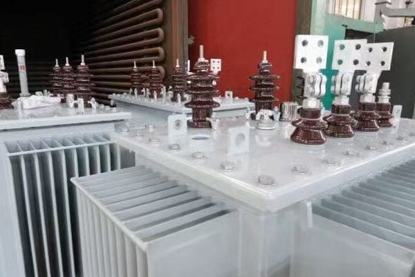
IEC (International Electrotechnical Commission) standards for transformer diagrams are widely used in Europe, Asia, and many other parts of the world. They provide a unified approach to representing transformer components, connections, and functions. IEC diagrams typically feature more graphical symbols, standardized layouts with high voltage on the left, and specific conventions for representing windings, taps, and protection devices.

Understanding IEC Transformer Diagram Standards
Let’s break down the key aspects of IEC transformer diagram standards:
- Symbol Conventions
- Layout and Organization
- Winding Representation
- Protection and Auxiliary Devices
- Application in Different Regions
Symbol Conventions
IEC standards use distinct symbols for transformer components:
- Transformers: Often represented by circles or ovals with lines inside
- Circuit breakers: Typically shown as two parallel lines with a slash
- Disconnectors: Usually depicted as a small gap in the line
I remember a project where an engineer familiar only with ANSI symbols misinterpreted an IEC circuit breaker symbol as a disconnector. This highlights the importance of understanding these symbol differences.
Layout and Organization
IEC diagrams follow specific layout conventions:
- High voltage side is typically on the left
- Low voltage side is usually on the right
- Auxiliary components are often shown at the bottom
During a recent international collaboration, our team’s adherence to these IEC layout conventions greatly facilitated communication with our European partners, streamlining the design review process.
Winding Representation
IEC standards have unique ways of showing transformer windings:
- Primary windings are often represented by thicker lines
- Secondary windings are usually shown with thinner lines
- Tertiary windings, if present, are typically depicted in the middle
I once worked on a project where understanding these winding representations was crucial in identifying a design flaw in a complex three-winding transformer.
Protection and Auxiliary Devices
IEC diagrams include standardized representations for various devices:
- Buchholz relays: Often shown as a small circle with internal markings
- Temperature indicators: Usually depicted as a thermometer symbol
- Tap changers: Represented with specific symbols indicating type (on-load or off-circuit)
In a recent retrofit project, correctly interpreting these IEC symbols for protection devices was essential in ensuring the new equipment integrated properly with the existing protection scheme.
Application in Different Regions
IEC standards are widely adopted but with some regional variations:
- Europe: Strict adherence to IEC standards
- Asia: Generally follows IEC with some local modifications
- Middle East: Often requires IEC compliance for international projects
Here’s a quick reference table for IEC diagram characteristics:
| Feature | IEC Standard Approach |
|---|---|
| Voltage Sides | High voltage on left |
| Symbol Style | More graphical |
| Winding Representation | Thickness indicates voltage level |
| Protection Devices | Standardized symbols |
| Global Acceptance | High in Europe and Asia |
Key considerations when working with IEC transformer diagrams:
- Familiarize yourself with IEC symbol conventions, especially if you’re used to ANSI standards
- Pay attention to the layout, as it provides quick insights into the transformer configuration
- Understand the significance of line thickness in winding representations
- Be aware of the standardized symbols for protection and auxiliary devices
- Consider regional variations in IEC standard application
In my experience, proficiency in reading and creating IEC transformer diagrams is invaluable for international projects. I’ve seen how this knowledge can prevent misunderstandings, reduce errors, and facilitate smoother collaborations across borders.
As we move forward, we’ll explore ANSI standards and how they compare to IEC. Understanding both will give you a comprehensive view of global transformer diagram practices, enhancing your ability to work on diverse projects and communicate effectively with international teams.
What Are ANSI Standards for Transformer Diagrams?
Are you puzzled by the differences in transformer diagrams when working on North American projects? ANSI standards can seem quite different from IEC, especially if you’re more familiar with the latter. But what exactly are ANSI standards for transformer diagrams, and how do they differ from their international counterparts?
ANSI (American National Standards Institute) standards for transformer diagrams are predominantly used in North America. They feature unique symbol conventions, flexible layout options, and specific labeling practices. ANSI diagrams often use more text-based labels, have different symbols for components like circuit breakers and transformers, and may not adhere to the left-to-right voltage level convention seen in IEC diagrams.
Diving into ANSI Transformer Diagram Standards
Let’s explore the key aspects of ANSI transformer diagram standards:
- Symbol Conventions
- Layout Flexibility
- Winding and Bushing Notation
- Protection and Control Devices
- Application in North America
Symbol Conventions
ANSI standards use distinct symbols that differ from IEC:
- Transformers: Often represented by a square or rectangle with circles inside
- Circuit breakers: Typically shown as a square with an open/close symbol
- Disconnectors: Usually depicted with a specific switch symbol
I recall a project where an engineer accustomed to IEC standards misinterpreted an ANSI circuit breaker symbol, leading to confusion in a protection scheme design. This experience underscored the importance of understanding these symbol differences.
Layout Flexibility
ANSI diagrams offer more flexibility in layout:
- No strict left-to-right voltage level convention
- Components can be arranged based on physical layout or functional grouping
- Emphasis on clarity and readability over standardized positioning
During a recent substation upgrade project in the US, this flexibility allowed us to create diagrams that closely mirrored the physical layout of the equipment, greatly aiding the installation team.
Winding and Bushing Notation
ANSI standards have specific conventions for representing windings and bushings:
- Bushings are typically labeled with H (high voltage) and X (low voltage)
- Winding polarity is often indicated with dot notation
- Tap changers are usually shown with detailed tap position information
I once worked on a transformer specification where understanding these ANSI notations was crucial in correctly defining the winding configuration and tap changer requirements.
Protection and Control Devices
ANSI diagrams include specific representations for various devices:
- Relays: Often shown with ANSI device numbers (e.g., 51 for overcurrent)
- Instrument transformers: Depicted with specific symbols for CTs and PTs
- Control switches: Represented with detailed switch diagrams
In a recent protection upgrade project, correctly interpreting these ANSI symbols and device numbers was essential in ensuring proper integration with existing systems.
Application in North America
ANSI standards are predominantly used in specific regions:
- United States: Primary standard for electrical diagrams
- Canada: Often uses ANSI standards, sometimes with CSA (Canadian Standards Association) modifications
- Parts of Latin America: May use ANSI standards, especially for projects involving US companies
Here’s a quick reference table for ANSI diagram characteristics:
| Feature | ANSI Standard Approach |
|---|---|
| Voltage Representation | No strict left-right convention |
| Symbol Style | More text and number based |
| Winding Notation | H and X labeling, dot notation |
| Protection Devices | ANSI device numbers |
| Regional Use | North America, parts of Latin America |
Key considerations when working with ANSI transformer diagrams:
- Familiarize yourself with ANSI symbol conventions, especially if you’re used to IEC standards
- Understand the flexibility in layout and how it can be used to enhance diagram clarity
- Pay attention to bushing and winding notations, as they differ significantly from IEC
- Learn ANSI device numbers for protection and control devices
- Be aware of potential variations in Canada and Latin America
In my experience, proficiency in reading and creating ANSI transformer diagrams is crucial for any project in North America. I’ve seen how this knowledge can streamline communication with US clients and contractors, reduce errors in specifications, and facilitate smoother project execution.
As we continue, we’ll compare IEC and ANSI standards directly, helping you understand when and how to apply each in your projects. This comparative knowledge is invaluable for engineers and managers working on international projects or dealing with global suppliers.
Key Differences Between IEC and ANSI Diagrams?
Are you finding it challenging to navigate between IEC and ANSI transformer diagrams in your international projects? You’re not alone. Many engineers and project managers struggle with the nuances between these two standards. But what are the key differences you need to be aware of to ensure smooth project execution across different regions?
IEC and ANSI transformer diagrams differ significantly in symbol conventions, layout practices, and notation systems. IEC diagrams typically use more graphical symbols, adhere to a left-to-right voltage level convention, and employ standardized component representations. ANSI diagrams often use more text-based labels, offer flexible layouts, and utilize specific numbering systems for devices. Understanding these differences is crucial for accurate interpretation and effective cross-border collaboration.

Comparing IEC and ANSI Transformer Diagram Standards
Let’s break down the key differences:
- Symbol Conventions
- Layout and Organization
- Winding and Bushing Notation
- Protection and Control Device Representation
- Regional Application and Compliance
Symbol Conventions
The most noticeable difference lies in how components are symbolized:
| Component | IEC Symbol | ANSI Symbol |
|---|---|---|
| Transformer | Circle or oval with lines | Square or rectangle with circles |
| Circuit Breaker | Two parallel lines with slash | Square with open/close symbol |
| Disconnector | Small gap in line | Specific switch symbol |
I recall a project where confusion between IEC and ANSI circuit breaker symbols led to a misunderstanding in a protection scheme. This experience highlighted the importance of clear communication about which standard is being used.
Layout and Organization
Layout conventions differ significantly:
| Aspect | IEC Approach | ANSI Approach |
|---|---|---|
| Voltage Levels | High voltage on left, low on right | No strict convention |
| Component Arrangement | Standardized positioning | Flexible, often based on physical layout |
| Auxiliary Components | Often at bottom of diagram | Can be placed flexibly |
During an international collaboration, we found that creating dual-standard diagrams – with both IEC and ANSI layouts side by side – greatly facilitated communication between our European and American teams.
Winding and Bushing Notation
Notation for windings and bushings varies:
| Feature | IEC Notation | ANSI Notation |
|---|---|---|
| Primary Bushings | Often numbered (1U, 1V, 1W) | Typically labeled (H1, H2, H3) |
| Secondary Bushings | Often numbered (2u, 2v, 2w) | Typically labeled (X1, X2, X3) |
| Winding Polarity | Arrow notation | Dot notation |
I once worked on a transformer specification where misinterpretation of these notations led to an incorrect winding configuration. This taught me the importance of clearly specifying which standard is being used in international tenders.
Protection and Control Device Representation
Representation of protection devices differs:
| Device | IEC Representation | ANSI Representation |
|---|---|---|
| Relays | Specific symbols | ANSI device numbers (e.g., 51 for overcurrent) |
| Instrument Transformers | Standardized symbols | Specific CT and PT symbols |
| Tap Changers | Specific symbols for type | Detailed tap position information |
In a recent protection upgrade project, understanding both IEC and ANSI representations was crucial in integrating new equipment with existing systems from different manufacturers.
Regional Application and Compliance
The use of these standards varies globally:
| Region | Predominant Standard | Notes |
|---|---|---|
| Europe | IEC | Strict adherence |
| Asia | IEC | Some local variations |
| North America | ANSI | Primary standard |
| Middle East | Often IEC | May require dual compliance |
| Latin America | Mixed | Often project-dependent |
During an international expansion project, we had to create dual-standard documentation to meet both European (IEC) and North American (ANSI) requirements. This approach, while initially more time-consuming, significantly smoothed our global operations.
Key considerations when dealing with IEC and ANSI differences:
- Always clearly specify which standard is being used in project documentation
- Develop expertise in both standards for international projects
- Consider creating dual-standard diagrams for global collaborations
- Be aware of regional variations and local requirements
- Invest in training for team members to understand both standards
In my experience, the ability to navigate between IEC and ANSI standards is invaluable in today’s globalized power industry. I’ve seen projects succeed or struggle based on how well these standard differences were managed.
For example, in a recent transformer export project from Europe to the US, we initially faced challenges due to misalignment in protection device representations. By creating a comprehensive cross-reference guide between IEC and ANSI symbols, we were able to bridge this gap effectively, ensuring smooth integration at the installation site.
Remember, the goal isn’t just to know the differences, but to use this knowledge to enhance communication, reduce errors, and facilitate smoother international collaborations. As you work on diverse projects, keep these differences in mind and always strive for clarity in your diagram choices and communications.
Compliance Tips for Export Projects?
Are you preparing for an export project involving transformers and feeling overwhelmed by the compliance requirements for different standards? You’re not alone. Many manufacturers and project managers find navigating the maze of IEC and ANSI standards challenging when exporting transformers. But what if you had a clear roadmap to ensure compliance and smooth project execution?
For export projects, ensure transformer diagrams comply with the destination country’s standards. When exporting to ANSI regions, convert IEC diagrams to ANSI format, paying attention to symbol changes, layout adjustments, and notation differences. For IEC destinations, focus on standardized layouts and graphical symbols. Always provide clear documentation on the standards used and consider dual-standard diagrams for critical components.

Essential Compliance Strategies for Transformer Export Projects
Let’s explore key strategies to ensure compliance:
- Standard Identification and Conversion
- Documentation and Clarity
- Training and Expertise Development
- Dual-Standard Approaches
- Regulatory Considerations
Standard Identification and Conversion
Start by clearly identifying the required standards:
- Determine the destination country’s preferred standard (IEC or ANSI)
- Assess any local variations or additional requirements
- Plan for conversion if your default standard differs from the destination’s
I once worked on a project exporting transformers from Europe to the US. We had to meticulously convert all our IEC diagrams to ANSI format. This process, while time-consuming, was crucial for regulatory approval and client satisfaction.
Documentation and Clarity
Ensure clear communication of standards in all documentation:
- Explicitly state which standard is used in each diagram
- Provide legend or key explaining symbols and notations
- Include cross-reference guides if multiple standards are involved
During a recent export to the Middle East, we included a comprehensive symbol guide in our documentation package. This proactive approach significantly reduced queries and potential misunderstandings during the approval process.
Training and Expertise Development
Invest in developing your team’s expertise:
- Provide training on both IEC and ANSI standards
- Develop internal experts who can guide standard compliance
- Consider certifications in international standards for key personnel
We implemented a training program for our engineering team to become proficient in both IEC and ANSI standards. This investment paid off in our ability to handle diverse international projects more efficiently.
Dual-Standard Approaches
Consider creating dual-standard documentation for critical components:
- Develop diagrams that show both IEC and ANSI representations
- Use side-by-side layouts for easy comparison
- Highlight key differences to prevent misinterpretation
In a complex project involving multiple international stakeholders, we created dual-standard diagrams for critical transformer components. This approach significantly facilitated communication and reduced errors during the integration phase.
Regulatory Considerations
Be aware of additional regulatory requirements:
- Research specific certifications needed in the destination country
- Understand how standards interact with local regulations (e.g., UL in the US)
- Plan for any additional testing or documentation required for compliance
Here’s a quick reference table for compliance considerations:
| Aspect | IEC Export | ANSI Export |
|---|---|---|
| Symbol Conversion | Minimal if any | Significant changes required |
| Layout Adjustment | Usually minor | May need complete reorganization |
| Additional Certifications | Often CE marking | UL/CSA certifications common |
| Documentation Language | Often multi-lingual | Typically English-only |
| Local Variations | Check for country-specific IEC adoptions | Be aware of differences between US and Canada |
Key tips for ensuring compliance in export projects:
- Start the compliance process early in the project timeline
- Engage with local experts or consultants in the destination country
- Conduct thorough reviews of converted diagrams to catch any missed details
- Prepare for potential site visits or audits by regulatory bodies
- Keep detailed records of all standard compliance efforts and decisions
In my experience, successful compliance in export projects comes down to thorough preparation and clear communication. I recall a project where we initially underestimated the time needed for ANSI conversion of our IEC diagrams. By reallocating resources and bringing in additional expertise, we were able to meet the deadline, but it was a valuable lesson in planning for standard compliance from the outset.
Remember, compliance isn’t just about meeting regulations; it’s about ensuring your transformers can be safely and effectively integrated into the destination’s power systems. By following these tips and maintaining a proactive approach to standards compliance, you can significantly increase the chances of success in your export projects, building a reputation for reliability in the global market.
Case Study: Diagram Misalignment in a US Export Project?
Have you ever wondered about the real-world consequences of misaligned transformer diagrams in international projects? Let’s explore a case study that highlights the critical importance of getting your diagrams right, especially when exporting to markets with different standards.
In a recent US export project, a European manufacturer’s use of IEC diagrams led to significant installation delays and additional costs. The ANSI-accustomed US team misinterpreted protection device symbols and winding configurations. This resulted in incorrect connections, requiring on-site engineering support and diagram conversions. The project faced a two-week delay and incurred substantial additional costs for rework and expedited shipping of correct components.

Analyzing the Diagram Misalignment Incident
Let’s break down this case study to understand what went wrong and how it could have been prevented:
- Project Background
- Key Issues Encountered
- Consequences of Misalignment
- Resolution Process
- Lessons Learned and Best Practices
Project Background
The project involved exporting a large power transformer from a European manufacturer to a US utility company:
- Transformer Rating: 100 MVA, 230kV/69kV
- Manufacturer: Based in Germany, typically using IEC standards
- Client: Major US utility company, familiar with ANSI standards
- Project Timeline: 18 months from order to planned commissioning
I was brought in as a consultant when issues started arising during the installation phase. The complexity of translating between IEC and ANSI standards became immediately apparent.
Key Issues Encountered
Several problems emerged due to diagram misalignment:
-
Protection Device Misinterpretation:
- IEC symbols for Buchholz relay and pressure relief devices were misunderstood
- US team incorrectly assumed functionalities based on ANSI symbol expectations
-
Winding Configuration Confusion:
- IEC winding notation led to misunderstanding of the transformer’s vector group
- Resulted in incorrect phasing during initial connection attempts
-
Tap Changer Representation:
- IEC-style tap changer diagram caused confusion about operating mechanisms
- Led to improper integration with the utility’s control systems
-
Bushing Terminal Labeling:
- IEC’s numerical system (1U, 1V, 1W) vs. ANSI’s letter system (H1, H2, H3) caused connection errors
During the initial installation attempt, I witnessed the confusion firsthand as the US team struggled to reconcile the IEC diagrams with their ANSI-based expectations.
Consequences of Misalignment
The diagram misalignment led to several serious issues:
-
Installation Delays:
- Project faced a two-week delay for diagram conversion and correction
- Knock-on effects on other scheduled maintenance works
-
Additional Costs:
- On-site engineering support required for diagram interpretation
- Rework of some connections and control wiring
- Expedited shipping for correct components
-
Safety Concerns:
- Potential for equipment damage due to incorrect connections
- Near-miss incident due to misunderstanding of protection schemes
-
Strained Client Relationships:
- Loss of confidence from the US utility company
- Increased scrutiny on future projects
The project manager estimated that these issues increased the overall project cost by approximately 15%, a significant overrun that could have been avoided.
Resolution Process
To resolve the issues, several steps were taken:
-
Emergency On-Site Support:
- Manufacturer sent IEC experts to collaborate with US team
- I facilitated daily workshops to bridge the knowledge gap
-
Comprehensive Diagram Conversion:
- All IEC diagrams were converted to ANSI format
- Created side-by-side comparisons for critical components
-
Revised Testing Procedures:
- Implemented additional testing phases to verify correct connections
- Developed new checklists incorporating both IEC and ANSI terminologies
-
Enhanced Communication Protocols:
- Established clear channels for technical queries
- Implemented daily cross-team meetings to address emerging issues
-
Documentation Overhaul:
- Created a comprehensive cross-reference guide for future projects
- Updated all project documents to include dual-standard notations
Lessons Learned and Best Practices
This case study highlighted several key learnings:
-
Proactive Standard Alignment:
- Identify and address standard differences at the project’s outset
- Consider creating dual-standard documentation for critical components
-
Enhanced Training:
- Provide cross-training on IEC and ANSI standards for key personnel
- Develop in-house expertise in standard conversion
-
Improved Communication:
- Clearly specify the applicable standards in all project documentation
- Establish protocols for addressing standard-related queries
-
Quality Control Measures:
- Implement additional review stages for diagram accuracy
- Conduct mock installations using provided diagrams before shipping
-
Client Engagement:
- Involve the client in early discussions about standards and expectations
- Provide educational materials on standard differences if necessary
In retrospect, this project served as a valuable lesson in the importance of standards alignment in international transformer projects. By implementing these lessons learned, we’ve significantly improved our approach to export projects, reducing risks and enhancing client satisfaction.
Remember, in the global power industry, understanding and effectively managing diagram standards is not just a technical necessity—it’s a crucial factor in project success and building long-term international partnerships.
Summary: Diagram Standard Choice Impacts Project Success?
Are you aware of how significantly your choice of transformer diagram standard can impact your project’s overall success? Many professionals underestimate the far-reaching effects of this seemingly technical decision. But how exactly does the selection between IEC and ANSI standards influence project outcomes, costs, and efficiency?
Choosing the appropriate transformer diagram standard (IEC or ANSI) is crucial for project success. It affects communication clarity, regulatory compliance, installation efficiency, and overall project costs. Using the wrong standard can lead to misinterpretations, delays, and expensive rework. Proper standard selection and management ensure smooth execution, especially in international projects, ultimately impacting project timelines, budgets, and stakeholder satisfaction.

The Ripple Effect of Diagram Standard Selection
Let’s explore how diagram standard choice influences key project aspects:
- Communication and Interpretation
- Regulatory Compliance and Approval
- Installation and Commissioning Efficiency
- Project Costs and Timelines
- Long-term Operational Impacts
Communication and Interpretation
The choice of standard directly affects how information is conveyed and understood:
- Mismatched standards can lead to misinterpretation of critical components
- Consistent standards enhance clarity in team communications
- Proper standard selection facilitates smoother international collaborations
I recall a project where using IEC diagrams in an ANSI-dominated market led to significant communication barriers. We had to invest additional time in creating interpretation guides, which could have been avoided with the right standard choice from the start.
Regulatory Compliance and Approval
Standard selection impacts the regulatory process:
- Using the region’s preferred standard can expedite approvals
- Misaligned standards may require additional documentation or reviews
- Some markets mandate specific standards for compliance
During a recent export project to North America, our initial use of IEC diagrams led to delays in regulatory approval. Switching to ANSI-compliant diagrams significantly streamlined the process.
Installation and Commissioning Efficiency
The right standard choice can greatly affect on-site efficiency:
- Familiar standards reduce installation time and errors
- Mismatched standards may require on-site interpretation, causing delays
- Proper standard selection ensures smoother integration with existing systems
I’ve witnessed how using the correct diagram standard can shave days off installation timelines, particularly in complex transformer projects where every connection counts.
Project Costs and Timelines
Standard selection has direct financial implications:
- Correct standards from the outset reduce the need for costly revisions
- Misaligned standards can lead to expensive rework and delays
- Proper selection can prevent the need for additional on-site technical support
Here’s a quick comparison of potential impacts:
| Aspect | Correct Standard Choice | Misaligned Standard |
|---|---|---|
| Timeline | As planned | Potential delays |
| Installation Costs | Within budget | Risk of overruns |
| Regulatory Approval | Streamlined | May require revisions |
| Team Efficiency | High | Reduced due to confusion |
Long-term Operational Impacts
The choice of standard can have lasting effects:
- Consistent standards simplify future maintenance and upgrades
- Mismatched standards may complicate spare parts management
- Proper selection ensures easier integration with future expansions
In a recent long-term power system upgrade project, consistently using ANSI standards across all phases ensured seamless integration of new equipment over a five-year period.
Key considerations for maximizing project success through proper standard selection:
-
Assess the Project Context:
- Understand the geographical and regulatory environment
- Consider the standards familiar to the end-user and maintenance teams
-
Plan for Standard Alignment Early:
- Address standard choices in the initial project planning phases
- Budget for potential standard conversion if necessary
-
Enhance Team Capabilities:
- Invest in training for both IEC and ANSI standards
- Develop in-house expertise in standard conversion and interpretation
-
Improve Documentation Practices:
- Clearly specify standards used in all project documents
- Consider dual-standard documentation for critical components
-
Engage Stakeholders:
- Discuss standard preferences with clients and regulators early
- Educate stakeholders on the implications of standard choices
In my experience, projects that carefully consider and manage diagram standards tend to run more smoothly, encounter fewer costly surprises, and achieve higher client satisfaction. I’ve seen how this approach not only improves immediate project outcomes but also enhances long-term operational efficiency and ease of maintenance.
Remember, the impact of your diagram standard choice extends far beyond the technical realm. It influences communication, compliance, efficiency, and ultimately, the overall success of your transformer projects. By carefully considering standard selection and implementing best practices in standard management, you can significantly improve your project outcomes and build a reputation for reliability in the global power industry.
Conclusion
Understanding and correctly applying IEC and ANSI standards for transformer diagrams is crucial for project success. Proper standard selection enhances communication, ensures compliance, improves efficiency, and reduces costs. Always consider the project’s context, plan early for standard alignment, and invest in team training to navigate these standards effectively in global transformer projects.
