Are you struggling with power limitations in your facility? Maybe you’re wondering how to upgrade from single-phase to three-phase power without breaking the bank. You’re not alone in this challenge.
Converting single-phase transformers into a three-phase system is a cost-effective solution for many businesses. This guide will walk you through the entire process, from understanding basic concepts to implementing the conversion, helping you make an informed decision for your power needs.

As an electrical engineer with over 20 years of experience, I’ve helped countless clients tackle this exact problem. In this comprehensive guide, I’ll share practical insights to help you understand and implement this conversion safely and efficiently. Whether you’re a seasoned pro or new to electrical systems, you’ll find valuable information here to power up your knowledge and your facility.
Power Basics: Unraveling Single-Phase and Three-Phase Systems?
Have you ever wondered why your home uses a different electrical system than a factory? The answer lies in the fundamental difference between single-phase and three-phase power. But what exactly sets these two systems apart?
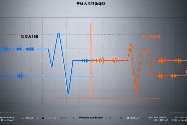
Single-phase power uses one alternating current, while three-phase uses three currents offset by 120 degrees. Three-phase is more efficient for large loads, delivering about 1.73 times more power with the same current and providing smoother operation for motors.
Let’s dive deeper into the world of power systems and explore the key differences between single-phase and three-phase:
Understanding the Power Flow: Single-Phase vs Three-Phase
-
Power Delivery:
- Single-Phase: One alternating current, two wires
- Three-Phase: Three alternating currents, three or four wires
-
Efficiency:
- Single-Phase: Less efficient for large loads (typically 70-80% efficient)
- Three-Phase: More efficient, especially for industrial applications (up to 95% efficient)
-
Applications:
- Single-Phase: Residential, small commercial (common in homes and small offices)
- Three-Phase: Industrial, large commercial, data centers (standard in factories and large buildings)
I remember a project where we were upgrading a small manufacturing plant’s power system. The owner was amazed to learn that switching to three-phase could reduce their energy costs by 15% and improve equipment performance. It was a lightbulb moment for both of us, highlighting the real-world impact of understanding these power systems.
Here’s a simple comparison table to illustrate the key differences:
| Characteristic | Single-Phase | Three-Phase |
|---|---|---|
| Number of wires | 2 (1 hot, 1 neutral) | 3 or 4 (3 hot, optional neutral) |
| Voltage waveform | One sine wave | Three sine waves, 120° apart |
| Power consistency | Pulsating | Constant |
| Typical voltage (US) | 120/240V | 208/240V or 480V |
| Load capacity | Lower | Higher (1.732 times more) |
| Motor starting | Less efficient | More efficient (30% better starting torque) |
| Typical applications | Homes, small offices | Factories, large buildings |
| Energy efficiency | Lower | Higher (up to 15% more efficient) |
Understanding these differences is crucial when planning your conversion from single-phase to three-phase power. It helps you appreciate the benefits you’ll gain and sets the foundation for the transformation process.
The Transformer Trio: Selecting Compatible Single-Phase Units?
Now that we understand the basics of single-phase and three-phase power, let’s focus on the heart of our conversion project: the transformers. But how do you choose the right single-phase transformers for a successful three-phase conversion?
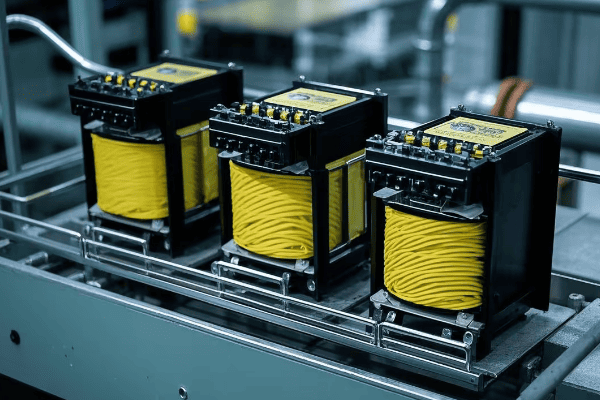
Selecting compatible single-phase transformers is crucial for a successful three-phase conversion. Key factors include matching voltage ratings, power capacity, impedance, and efficiency. All three units must have identical specifications to ensure balanced operation and optimal performance of the converted system.
Let’s explore the critical aspects of transformer selection for your conversion project:
The Perfect Match: Choosing Your Transformer Trio
-
Voltage Ratings:
- Primary voltage: Must match your input supply (e.g., 480V in US, 400V in EU)
- Secondary voltage: Determine based on load requirements
- Tap settings: Consider transformers with multiple taps for flexibility
-
Power Capacity:
- Calculate total load requirements
- Each transformer should handle 1/3 of the total load
- Allow for future expansion (typically 20-30% extra capacity)
-
Impedance Matching:
- All three transformers should have the same impedance (within 0.3% tolerance)
- Typical range: 2-5% for distribution transformers
- Matching impedance ensures balanced current flow and minimizes circulating currents
-
Efficiency Considerations:
- Look for high-efficiency models to reduce losses
- Consider total cost of ownership, not just initial price
- Check for compliance with energy efficiency standards (e.g., DOE 2016 in US, IE3 in EU)
I once consulted on a project for a multinational corporation setting up a factory in Mexico. They initially planned to use transformers from their US supplier, but we quickly realized these wouldn’t meet local voltage standards or efficiency requirements. By selecting locally manufactured transformers that met both IEC and NOM (Mexican) standards, we ensured compliance and optimal performance.
Here’s a detailed comparison table to guide your transformer selection:
| Specification | Why It’s Important | What to Look For | Potential Issues if Mismatched |
|---|---|---|---|
| Voltage Rating | Ensures compatibility with system | Exact match to system voltage | Overvoltage or undervoltage conditions |
| kVA Rating | Determines power handling capacity | Sum of three should exceed total load | Overloading, reduced efficiency |
| Impedance | Affects fault currents and voltage regulation | Must be identical for all three (±0.3%) | Unbalanced currents, overheating |
| Efficiency | Impacts operating costs | Look for high efficiency models (>98%) | Higher energy costs, increased heat generation |
| Temperature Rise | Indicates cooling effectiveness | 65°C rise common (80°C in hot climates) | Reduced lifespan, potential failure |
| BIL (Basic Impulse Level) | Protects against voltage surges | Should match or exceed system requirements | Vulnerability to transient overvoltages |
| Taps | Allows for voltage adjustment | 5-position taps offer good flexibility | Inability to fine-tune voltage |
| Vector Group | Affects phase relationships | Typically Dyn11 for distribution transformers | Phase shift issues, potential system instability |
| Cooling Method | Determines installation requirements | ONAN is most common for smaller sizes | Inadequate cooling, reduced capacity |
Remember, the cheapest option isn’t always the most cost-effective in the long run. Consider the total cost of ownership, including energy costs and maintenance, when making your selection. It’s often worth investing in higher quality, more efficient transformers to ensure the longevity and reliability of your three-phase system.
Wiring Wizardry: Mastering Delta and Wye Connections?
Now that we’ve selected our transformer trio, it’s time to connect them. But how exactly do we wire these single-phase units to create a three-phase system? This is where Delta and Wye connections come into play.
Delta and Wye are two fundamental ways to connect three-phase transformers. Delta forms a triangle, while Wye forms a star with a neutral point. The choice between them affects voltage relationships, current flow, and system grounding. Most three-phase conversions use a Delta-Wye configuration for optimal performance.

Let’s dive into the details of these connections and understand their roles in our three-phase system:
Decoding Delta and Wye: The Heart of Three-Phase Power
-
Delta Connection:
- Shape: Triangular configuration
- Voltage: Line voltage = Phase voltage
- Current: Line current = √3 × Phase current
- Uses: Often used on the primary (high voltage) side
- Advantages: Good for balancing loads, no neutral needed
-
Wye (Star) Connection:
- Shape: Star configuration with a neutral point
- Voltage: Line voltage = √3 × Phase voltage
- Current: Line current = Phase current
- Uses: Common on the secondary (low voltage) side
- Advantages: Provides a neutral for single-phase loads, good for unbalanced loads
In a recent project for a manufacturing plant, we used a Delta-Wye configuration. We connected the primary side in Delta to handle load balancing efficiently, and the secondary side in Wye to provide a neutral for office equipment. This combination offered the best of both worlds, showcasing how understanding these connections can lead to optimal system design.
Here’s a detailed comparison of Delta and Wye connections:
| Characteristic | Delta Connection | Wye Connection |
|---|---|---|
| Symbol | Δ | Y |
| Neutral point | No | Yes |
| Voltage relationship | VLine = VPhase | VLine = √3 × VPhase |
| Current relationship | ILine = √3 × IPhase | ILine = IPhase |
| Harmonic handling | Blocks 3rd harmonics | Allows 3rd harmonics |
| Ground fault detection | More challenging | Easier |
| Typical use | Primary side | Secondary side |
| Balanced load handling | Excellent | Good |
| Unbalanced load handling | Good | Excellent |
When converting single-phase transformers to a three-phase system, we typically connect the primary windings in Delta and the secondary windings in Wye. This Delta-Wye configuration offers several advantages:
- It provides a neutral point on the secondary side, which is useful for powering single-phase loads.
- It helps in suppressing harmonics, improving power quality.
- It allows for easier ground fault detection on the secondary side.
Remember, the choice between Delta and Wye can significantly impact your system’s performance, efficiency, and safety. As you plan your conversion, consider your specific needs and consult with an expert if you’re unsure about the best configuration for your application.
Blueprint for Success: Planning Your Three-Phase Conversion Project?
With our transformers selected and our connection strategy in place, it’s time to plan the conversion project. But where do you start, and what factors should you consider to ensure a smooth transition?
Planning a three-phase conversion involves assessing power needs, evaluating existing infrastructure, understanding local regulations, and preparing for potential challenges. A well-planned project can save time, money, and prevent safety issues during the conversion process.

Let’s break down the key steps in planning your conversion project:
Crafting Your Conversion Roadmap: From Concept to Completion
-
Assess Your Power Needs:
- Calculate your total power requirements
- Consider future expansion plans
- Identify any specific voltage or current needs
-
Evaluate Existing Infrastructure:
- Check the capacity of your electrical service
- Assess the condition of your electrical panels and wiring
- Determine if any equipment upgrades are necessary
-
Understand Regulations:
- Research local electrical codes and standards
- Determine if permits are required for the conversion
- Consider hiring a licensed electrician if required by law
-
Create a Detailed Project Plan:
- Outline each step of the conversion process
- Assign responsibilities to team members or contractors
- Set realistic timelines for each phase of the project
-
Budget and Financial Planning:
- Estimate costs for equipment, labor, and potential downtime
- Consider energy savings and ROI in your financial analysis
- Explore financing options if needed
I once worked with a client who skipped the planning phase and jumped straight into conversion. Halfway through, we discovered their existing wiring couldn’t handle the new load, leading to costly delays and rewiring. This experience taught me the invaluable lesson of thorough planning.
Here’s a checklist to guide your planning process:
| Planning Step | Key Considerations | Potential Pitfalls |
|---|---|---|
| Power Assessment | Total load, future growth | Underestimating power needs |
| Infrastructure Evaluation | Service capacity, wiring condition | Inadequate infrastructure |
| Regulatory Compliance | Local codes, permits | Legal issues, failed inspections |
| Project Planning | Step-by-step process, timelines | Overlooked tasks, delays |
| Budgeting | Equipment costs, labor, downtime | Unexpected expenses |
| ROI Analysis | Energy savings, productivity gains | Overestimating benefits |
| Team Assembly | Skills needed, roles assignment | Lack of expertise |
| Risk Assessment | Potential challenges, mitigation strategies | Unforeseen problems |
Remember, proper planning is the foundation of a successful conversion project. Take the time to thoroughly assess your needs, understand the requirements, and prepare for potential challenges. This upfront investment will pay off in smoother execution, fewer surprises, and a more efficient three-phase system in the end.
Safety First: Essential Precautions for High-Voltage Transformations?
As we gear up for the actual conversion process, it’s crucial to address the elephant in the room: safety. Working with high-voltage systems is inherently dangerous, but how can we minimize risks and ensure a safe conversion process?
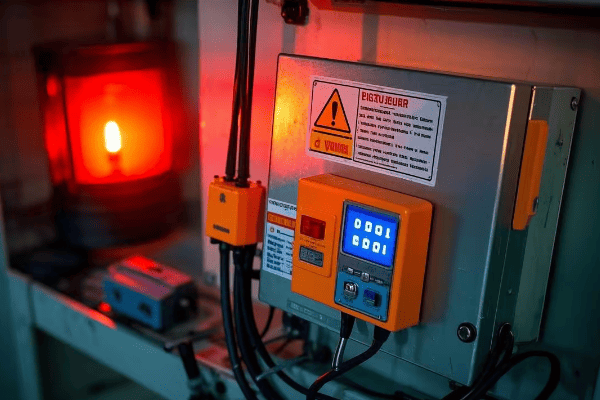
High-voltage transformer conversions pose serious risks including electric shock, arc flash, and fire. Essential safety measures include proper personal protective equipment (PPE), lockout/tagout procedures, grounding, and adherence to electrical codes. Prioritizing safety can prevent accidents and save lives.
Let’s explore the critical safety precautions you should take during your conversion project:
Safeguarding Your Project: A Comprehensive Safety Approach
-
Personal Protective Equipment (PPE):
- Insulated gloves rated for the voltage level
- Arc-flash rated face shield and clothing
- Safety glasses and steel-toed boots
-
Lockout/Tagout Procedures:
- Identify all power sources
- Disconnect and lock out all electrical supplies
- Use "Do Not Operate" tags to prevent accidental energization
-
Grounding and Bonding:
- Properly ground all transformer cases
- Use temporary grounding cables during work
- Verify integrity of grounding connections
-
Workspace Safety:
- Ensure adequate lighting and ventilation
- Keep work area clean and free of obstacles
- Have a fire extinguisher rated for electrical fires nearby
-
Training and Certification:
- Ensure all workers are properly trained in electrical safety
- Verify certifications for high-voltage work
- Conduct regular safety briefings throughout the project
I once witnessed a near-miss incident where a technician, accustomed to different color codes, misidentified a live wire. This experience reinforced the importance of understanding and adhering to local standards, even for experienced professionals.
Here’s a comprehensive safety checklist for your conversion project:
| Safety Aspect | Key Actions | Why It’s Critical |
|---|---|---|
| Risk Assessment | Identify potential hazards | Prevents unforeseen dangers |
| PPE | Wear appropriate gear | Protects against shock and arc flash |
| Lockout/Tagout | Secure all power sources | Prevents accidental energization |
| Grounding | Properly ground all equipment | Protects against stray voltages |
| Insulation Testing | Check insulation integrity | Prevents insulation failures |
| Voltage Testing | Verify de-energized state | Ensures safe working conditions |
| Workspace | Keep area clean and organized | Reduces accidents and improves focus |
| Communication | Inform all team members of procedures | Ensures everyone is on the same page |
| Emergency Procedures | Know what to do in case of accident | Speeds up response in critical situations |
| Documentation | Record all safety steps taken | Provides accountability and learning opportunities |
Remember, no project is worth risking safety. Always prioritize safety measures and create a culture of safety awareness among all team members. It’s better to take extra time to ensure safety than to rush and risk an accident.
The Conversion Process: Step-by-Step Guide to Three-Phase Integration?
Now that we’ve covered the essentials of planning and safety, it’s time to roll up our sleeves and dive into the actual conversion process. But how exactly do we transform our single-phase transformers into a functioning three-phase system?
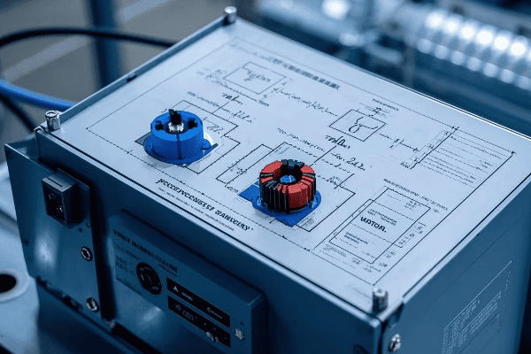
Converting single-phase transformers to a three-phase system involves carefully connecting the primary and secondary windings in specific configurations, typically Delta for the primary and Wye for the secondary. This process requires precise measurements, proper insulation, and attention to phase relationships to ensure a balanced and efficient three-phase output.
Let’s break down the conversion process into manageable steps:
From Single to Three: A Step-by-Step Transformation Guide
-
Preparation:
- Gather three identical single-phase transformers
- Ensure all transformers have the same voltage ratings and capacity
- Collect necessary tools: multimeter, insulation tester, phase rotation meter
-
Primary Winding Connection (Delta):
- Identify the primary terminals of each transformer
- Connect the end of the first transformer to the start of the second
- Connect the end of the second to the start of the third
- Connect the end of the third to the start of the first
-
Secondary Winding Connection (Wye):
- Identify the secondary terminals of each transformer
- Connect one end of each transformer’s secondary to a common point (neutral)
- The other ends become the three phases of your output
-
Insulation and Protection:
- Apply appropriate insulation to all connections
- Install overcurrent protection devices for each phase
-
Testing and Verification:
- Check all connections for tightness and proper insulation
- Measure voltages between phases and phase-to-neutral
- Verify phase rotation (clockwise in most countries, counter-clockwise in some)
-
Load Connection:
- Connect your three-phase load to the three output phases
- Ensure balanced loading across all phases
I remember a challenging conversion project for a small factory in a remote area. We had limited resources, so precision was key. By meticulously following these steps and double-checking each connection, we successfully created a stable three-phase system that significantly improved their production efficiency.
Here’s a detailed checklist for the conversion process:
| Step | Action | Key Considerations | Potential Issues |
|---|---|---|---|
| 1. Preparation | Gather materials and tools | Matching transformer specs | Mismatched transformers |
| 2. Primary Connection | Create Delta configuration | Correct polarity, tight connections | Reversed polarity, loose connections |
| 3. Secondary Connection | Create Wye configuration | Proper neutral point, balanced phases | Unbalanced voltages |
| 4. Insulation | Apply insulation to all connections | Appropriate materials for voltage | Inadequate insulation, short circuits |
| 5. Protection | Install overcurrent devices | Proper sizing of protection | Overloading, equipment damage |
| 6. Testing | Measure voltages, check rotation | Use calibrated instruments | Incorrect measurements, wrong rotation |
| 7. Load Connection | Connect three-phase load | Balanced loading | Overloading single phase |
Remember, this process involves working with high voltages and currents. If you’re not comfortable or experienced with electrical work, it’s crucial to consult or hire a professional electrician. Safety should always be your top priority throughout the conversion process.
Testing and Troubleshooting: Ensuring Your New System Performs Flawlessly?
With our three-phase system now assembled, it’s time to put it to the test. But what checks should we perform, and how do we troubleshoot any issues that arise?
Testing a newly converted three-phase system involves checking voltage levels, phase balance, rotation, and load performance. Key tests include no-load tests, load tests, and insulation resistance tests. Proper testing and troubleshooting ensure system safety, efficiency, and longevity.

Let’s dive into the essential testing procedures and troubleshooting tips:
From Theory to Practice: Testing and Fine-Tuning Your Three-Phase System
-
No-Load Testing:
- Measure voltages between phases and phase-to-neutral
- Check for balanced voltages (should be within 1% of each other)
- Verify correct phase rotation
-
Load Testing:
- Gradually apply balanced load to the system
- Monitor voltage regulation under load
- Check for any unusual heating or noise
-
Insulation Resistance Testing:
- Use a megohmmeter to test insulation integrity
- Perform tests between windings and from windings to ground
- Compare results to manufacturer’s specifications
-
Power Quality Analysis:
- Use a power quality analyzer to check for harmonics
- Measure power factor under various load conditions
- Identify any voltage or current imbalances
-
Thermal Imaging:
- Use an infrared camera to check for hot spots
- Inspect connections and windings for abnormal heating
- Compare temperatures across all three phases
I once worked on a project where initial testing revealed a significant voltage imbalance. After careful troubleshooting, we discovered a loose connection in one of the transformer’s primary windings. Fixing this issue before putting the system into full operation prevented potential equipment damage and downtime.
Here’s a troubleshooting guide for common issues:
| Issue | Possible Causes | Troubleshooting Steps |
|---|---|---|
| Voltage Imbalance | Loose connections, uneven loads | Check all connections, redistribute loads |
| Incorrect Phase Rotation | Wiring errors | Swap any two phase connections |
| Overheating | Overloading, poor ventilation | Reduce load, improve cooling |
| Low Insulation Resistance | Moisture, contamination | Dry out transformers, clean windings |
| Harmonics | Non-linear loads | Install harmonic filters, redistribute loads |
| Power Factor Issues | Inductive loads | Add power factor correction capacitors |
| Noise or Vibration | Loose components, resonance | Tighten connections, check for mechanical issues |
Remember, thorough testing and prompt troubleshooting are key to ensuring the reliability and efficiency of your newly converted three-phase system. If you encounter issues you can’t resolve or if you’re unsure about any test results, don’t hesitate to consult with a professional. It’s always better to address potential problems early rather than risk system failure down the line.
Future-Proofing Your Setup: Adapting to Emerging Power Technologies?
As we wrap up our three-phase conversion project, it’s important to look ahead. How can we ensure our newly converted system remains relevant and efficient in the face of rapidly evolving power technologies?
Future-proofing your three-phase system involves considering smart grid integration, renewable energy compatibility, and evolving efficiency standards. Implementing flexible designs, incorporating digital monitoring systems, and staying informed about global trends can help your system remain efficient and compliant for years to come.

Let’s explore key strategies for keeping your system ahead of the curve:
Embracing the Future: Keeping Your Three-Phase System Cutting-Edge
-
Smart Grid Integration:
- Implement digital monitoring and control systems
- Consider compatibility with demand response programs
- Prepare for bi-directional power flow capabilities
-
Renewable Energy Compatibility:
- Design for integration with solar and wind power systems
- Consider energy storage integration for load balancing
- Implement inverter-friendly protection schemes
-
Efficiency Standards Evolution:
- Stay informed about upcoming efficiency regulations
- Plan for potential retrofits or replacements to meet future standards
- Consider ultra-high efficiency transformers for long-term savings
-
Advanced Materials and Designs:
- Explore amorphous core transformers for reduced losses
- Consider solid-state transformers for improved control and efficiency
- Investigate high-temperature superconducting transformers for specialized applications
-
Cybersecurity Considerations:
- Implement robust security measures for digital control systems
- Plan for regular security audits and updates
- Consider physical security measures for critical infrastructure
I recently worked on a project upgrading a manufacturing plant’s power system. We incorporated a flexible design that allowed for easy integration of planned solar installations and future energy storage systems. By thinking ahead, we created a system that not only met current needs but was also ready for the company’s future sustainability goals.
Here’s a table summarizing key future-proofing strategies and their implications:
| Strategy | Description | Benefits | Global Trends |
|---|---|---|---|
| Smart Grid Readiness | Implementing digital monitoring and control | Improved efficiency and grid stability | Rapid adoption in developed countries |
| Renewable Integration | Designing for solar and wind power compatibility | Reduced carbon footprint, potential cost savings | Growing worldwide, led by EU and China |
| Efficiency Standard Compliance | Planning for future efficiency requirements | Long-term cost savings, regulatory compliance | Increasingly stringent globally |
| Advanced Materials Adoption | Using new core materials and designs | Reduced losses, improved performance | Growing interest, especially in high-cost energy markets |
| Cybersecurity Implementation | Securing digital systems against threats | Protected operations, compliance with security standards | Critical focus in all regions |
| Modular Design | Creating systems that can be easily upgraded | Flexibility for future needs, reduced replacement costs | Gaining popularity in fast-evolving industries |
| Energy Storage Readiness | Preparing for battery or other storage integration | Improved reliability, peak shaving capabilities | Rapid growth, especially in areas with unstable grids |
| Power Quality Enhancement | Implementing harmonic mitigation and voltage stabilization | Improved equipment life, reduced downtime | Critical in sensitive industrial and data center applications |
Remember, the power industry is constantly evolving. By staying informed about emerging technologies and trends, and designing your system with flexibility in mind, you can ensure that your three-phase conversion investment continues to pay dividends well into the future.
Conclusion
Transforming single-phase transformers into a three-phase system is a complex but rewarding process. By understanding the basics, carefully planning, prioritizing safety, and implementing best practices in conversion and testing, you can successfully unlock the power of three-phase electricity for your facility. Remember to consider future trends and technologies to ensure your system remains efficient and relevant for years to come.
