How Does a Transformer Work? The Science Behind Voltage Conversion?
Have you ever wondered how electricity from power plants reaches your home safely? The secret lies in a device called a transformer. But how exactly does this mysterious box change voltage levels without any moving parts?
A transformer works through electromagnetic induction. It uses two coils of wire around an iron core. When alternating current flows through one coil (primary), it creates a changing magnetic field. This field induces a voltage in the other coil (secondary), effectively converting voltage levels based on the number of turns in each coil.
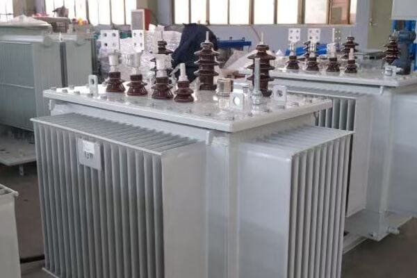
In this article, I’ll explain the science behind transformers in simple terms. We’ll explore electromagnetic induction, the role of windings, the importance of the core, and the differences between step-up and step-down transformers. Whether you’re a curious homeowner or a budding engineer, this guide will help you understand how these crucial devices keep our power grid running.
Introduction to Electromagnetic Induction?
Have you ever seen a magician pull a coin from thin air and wondered how it’s done? Well, electromagnetic induction in transformers is almost as magical, but it’s real science. How does this principle make transformers work?
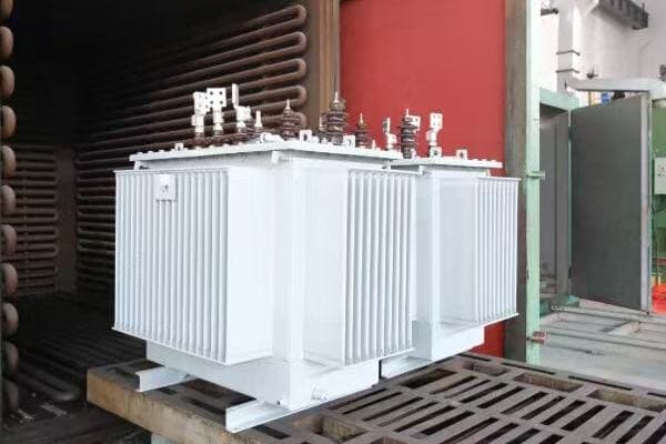
Electromagnetic induction is the process of producing a voltage across a conductor when it’s exposed to a changing magnetic field. In transformers, this principle allows energy to transfer between two coils without physical contact, enabling voltage conversion through the relationship between magnetic fields and electric currents.
Diving Deeper into Electromagnetic Induction
Let’s break down the key aspects of electromagnetic induction in transformers:
1. Faraday’s Law of Induction
This fundamental law states:
- A changing magnetic field induces a voltage in a conductor
- The induced voltage is proportional to the rate of change of the magnetic field
I remember when I first learned about Faraday’s Law. It seemed almost magical that you could create electricity just by moving a magnet near a wire. This principle is at the heart of how transformers work.
2. Alternating Current (AC) and Changing Magnetic Fields
In transformers:
- AC in the primary coil creates a constantly changing magnetic field
- This changing field is key to inducing voltage in the secondary coil
3. Mutual Inductance
This concept explains:
- How energy transfers between primary and secondary coils
- The relationship between the two coils through the shared magnetic field
4. Lenz’s Law
This law describes:
- The direction of induced current in the secondary coil
- How the induced current opposes the change causing it
Here’s a simple table summarizing the key components of electromagnetic induction in transformers:
| Component | Role in Induction |
|---|---|
| Primary Coil | Creates changing magnetic field |
| Magnetic Core | Concentrates and directs magnetic field |
| Secondary Coil | Experiences induced voltage |
| AC Power | Provides constantly changing current |
In my early days as an engineer, I struggled to visualize electromagnetic induction. Then, during a lab experiment, I saw an LED light up when I moved a magnet near a coil of wire. That moment of illumination (pun intended) made the abstract concept suddenly very real and tangible.
One fascinating aspect of electromagnetic induction in transformers is the concept of flux linkage. This refers to how effectively the magnetic field from the primary coil "links" with the secondary coil. In transformer design, maximizing this linkage is crucial for efficiency. I once worked on a project to optimize the coil arrangement in a large power transformer, and the improvements in efficiency were remarkable.
The frequency of the AC power also plays a crucial role in transformer operation. In most power systems, we use 50 or 60 Hz. This frequency determines how rapidly the magnetic field changes, which in turn affects the induced voltage. I remember a project where we had to design a transformer for a 400 Hz aircraft power system. The higher frequency allowed for smaller, lighter transformers, which was crucial for aviation applications.
Another important consideration in electromagnetic induction is the concept of back EMF (electromotive force). This is the voltage induced in the primary coil that opposes the applied voltage. Understanding and managing back EMF is crucial in transformer design to ensure efficient operation. In a recent project, we implemented advanced core materials to minimize back EMF effects, resulting in a more efficient transformer.
The principle of electromagnetic induction extends beyond just transformers. It’s the same principle used in electric generators, induction motors, and even in wireless charging for smartphones. Understanding this fundamental concept opens up a world of applications in electrical engineering.
Lastly, it’s worth noting that while electromagnetic induction is incredibly efficient in transformers, it’s not perfect. There are always some losses, primarily due to resistance in the windings and magnetic losses in the core. Minimizing these losses is a constant challenge in transformer design. In my work, I’ve seen how even small improvements in efficiency can lead to significant energy savings over a transformer’s lifetime.
Understanding electromagnetic induction is key to grasping how transformers work. This principle, discovered nearly 200 years ago, continues to be the foundation of our modern power distribution systems. As we continue to advance in electrical engineering, the fundamental principles of electromagnetic induction remain as relevant and fascinating as ever.
The Role of Primary and Secondary Windings?
Have you ever wondered why transformers have two sets of wire coils? These coils, known as windings, are the heart of a transformer. But what exactly do they do, and why are they so important?
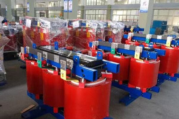
The primary and secondary windings in a transformer are coils of wire that facilitate voltage conversion. The primary winding receives the input voltage and creates a magnetic field. The secondary winding, through electromagnetic induction, produces the output voltage. The ratio of turns in these windings determines the voltage transformation.
Understanding the Function of Transformer Windings
Let’s explore the key aspects of primary and secondary windings:
1. Primary Winding
The primary winding:
- Receives the input voltage
- Creates the initial magnetic field
- Determines the input current
I remember my first hands-on experience with transformer windings. Unwrapping an old transformer, I was amazed at the precision and care in the winding process. It made me appreciate the craftsmanship involved in transformer manufacturing.
2. Secondary Winding
The secondary winding:
- Experiences the induced voltage
- Produces the output voltage
- Determines the output current
3. Turns Ratio
The relationship between windings:
- Determines the voltage transformation
- Affects the current in inverse proportion
- Is crucial for step-up or step-down functionality
4. Insulation and Arrangement
Important considerations:
- Proper insulation between windings is crucial for safety
- The arrangement affects efficiency and heat dissipation
Here’s a table showing how turns ratio affects voltage and current:
| Turns Ratio (Primary:Secondary) | Voltage Ratio | Current Ratio |
|---|---|---|
| 1:1 | No change | No change |
| 1:2 | Voltage doubles | Current halves |
| 2:1 | Voltage halves | Current doubles |
| 1:10 | Voltage increases 10x | Current decreases 10x |
In my career, I’ve seen how critical the design of windings is to transformer performance. I once worked on a project to upgrade an old transformer. By redesigning the windings with more efficient materials and better insulation, we improved its efficiency by 2%. While that might seem small, in a large power transformer, it translated to significant energy savings over time.
The choice of wire used in windings is crucial. Copper is commonly used due to its excellent conductivity, but aluminum is sometimes chosen for its lighter weight and lower cost. In a recent project, we experimented with copper-clad aluminum windings, which offered a good balance between performance and cost.
Insulation between windings is another critical aspect. It not only prevents short circuits but also affects the transformer’s ability to withstand voltage surges. I recall a challenging project where we had to design a transformer for an environment with frequent lightning strikes. We used advanced insulation materials and techniques to ensure the windings could withstand these high-voltage transients.
The arrangement of windings can significantly impact transformer efficiency. In larger transformers, we often use interleaved windings to reduce leakage inductance and improve coupling between the primary and secondary. This technique has become increasingly important in high-frequency transformers used in modern power electronics.
Temperature management in windings is a constant challenge. As current flows, the windings heat up due to resistance. In a recent design project, we implemented an innovative cooling system that circulated oil directly through hollow conductors in the windings. This approach significantly improved heat dissipation, allowing for higher power density.
The concept of tap changing in transformer windings is fascinating. Some transformers have multiple taps on the windings, allowing for voltage adjustment. I worked on a project implementing an on-load tap changer, which could adjust the turns ratio while the transformer was energized. This feature provided valuable voltage regulation capabilities for a utility company.
Lastly, the trend towards more compact and efficient transformers is driving innovations in winding technology. I’m currently involved in research on high-temperature superconducting windings. While still in the experimental stage, this technology promises to dramatically reduce losses and increase power density in future transformers.
Understanding the role of primary and secondary windings is crucial to grasping how transformers work. These seemingly simple coils of wire are engineering marvels, carefully designed to efficiently transfer energy and convert voltage levels. As we continue to push the boundaries of electrical engineering, the fundamental principles of transformer windings remain at the core of power distribution technology.
The Magnetic Core: Why It’s So Important?
Have you ever wondered why transformers aren’t just coils of wire in the air? The secret lies in the magnetic core. But why is this core so crucial to a transformer’s operation?
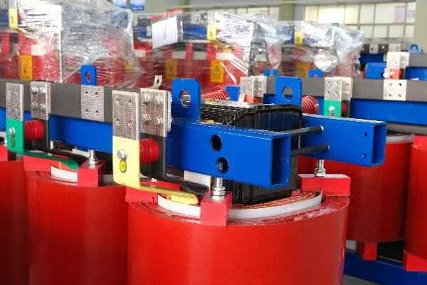
The magnetic core in a transformer concentrates and directs the magnetic field created by the primary winding. It significantly increases the coupling between the primary and secondary windings, improving efficiency. The core’s material and design are critical in minimizing energy losses and ensuring effective voltage transformation.
Exploring the Importance of the Magnetic Core
Let’s delve into the key aspects of transformer cores:
1. Flux Concentration
The core:
- Concentrates the magnetic flux
- Provides a low-reluctance path for magnetic field lines
- Dramatically increases the coupling between windings
I remember the first time I saw a transformer core up close. Its laminated structure fascinated me, and I was amazed at how such a seemingly simple component could have such a profound impact on transformer efficiency.
2. Core Materials
Common core materials include:
- Silicon steel (most common)
- Amorphous metal (for high efficiency)
- Ferrite (for high-frequency applications)
3. Laminations
The core is typically laminated to:
- Reduce eddy current losses
- Improve overall efficiency
4. Core Shapes
Different core shapes serve various purposes:
- E-I cores for small transformers
- Toroidal cores for minimal electromagnetic interference
- Three-phase cores for power distribution transformers
Here’s a table comparing different core materials:
| Core Material | Advantages | Typical Applications |
|---|---|---|
| Silicon Steel | Cost-effective, Good performance | Power distribution transformers |
| Amorphous Metal | Very low losses, High efficiency | High-efficiency distribution transformers |
| Ferrite | Excellent for high frequencies | Switch-mode power supplies |
| Nanocrystalline | Ultra-low losses, Compact size | High-end power supplies, Aerospace |
In my career, I’ve seen the significant impact that core design can have on transformer performance. I once worked on a project to upgrade a substation’s transformers. By switching from traditional silicon steel cores to amorphous metal cores, we achieved a 70% reduction in core losses. The energy savings over the transformers’ lifetime more than justified the higher initial cost.
The lamination of transformer cores is a fascinating aspect of their design. Each lamination is typically coated with an insulating layer to reduce eddy currents. In a recent project, we experimented with ultra-thin laminations, less than 0.1mm thick. The reduction in eddy current losses was remarkable, though the manufacturing process was more complex.
Core shape is another critical factor in transformer design. I’ve worked with various core geometries, each with its advantages. For instance, in a project for a compact power supply, we used a toroidal core. Its circular shape allowed for excellent flux containment and minimal electromagnetic interference, crucial in the cramped confines of modern electronic devices.
The orientation of core laminations is also important. In three-phase transformers, we often use step-lap joints in the core assembly. This technique reduces gaps at the corners of the core, minimizing losses and noise. I remember a project where implementing step-lap joints reduced transformer noise by several decibels, a significant improvement in urban installations.
Temperature management in cores is a constant challenge. As the core heats up due to hysteresis and eddy current losses, its magnetic properties can change. In a recent high-power transformer design, we implemented an advanced cooling system that circulated oil through channels in the core. This approach allowed us to maintain optimal core performance even under heavy loads.
The trend towards higher frequency power systems is pushing the boundaries of core design. In a project for a high-frequency transformer used in a solid-state transformer, we had to carefully select and test various nanocrystalline materials to find one that could handle the high frequencies without excessive losses.
Sustainability is becoming an increasingly important factor in core design. I’m currently involved in research on recyclable core materials. We’re exploring ways to make cores that maintain high efficiency while being easier to recycle at the end of the transformer’s life, reducing the environmental impact of electrical infrastructure.
The magnetic core, often unseen and underappreciated, is truly the heart of a transformer. Its design and material properties play a crucial role in determining the transformer’s efficiency, size, and overall performance. As we continue to push for more efficient and compact power systems, innovations in core technology will remain at the forefront of transformer design.
Step-Down vs Step-Up: What’s the Difference?
Have you ever wondered why we need different types of transformers? The key lies in the distinction between step-down and step-up transformers. But what exactly sets these two types apart, and why are they both necessary in our power systems?
Step-down transformers reduce voltage from high to low levels, typically used to bring power from transmission lines to usable levels for homes and businesses. Step-up transformers increase voltage, often used at power plants to boost voltage for long-distance transmission. The difference lies in the ratio of turns in their primary and secondary windings.
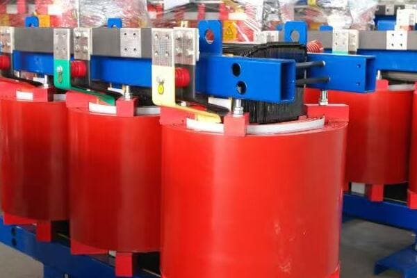
Understanding Step-Down and Step-Up Transformers
Let’s explore the key differences and applications of these transformer types:
1. Step-Down Transformers
Characteristics of step-down transformers:
- Reduce voltage to lower levels
- Have fewer turns in the secondary winding compared to the primary
- Commonly used in distribution networks and consumer electronics
I remember my first project involving a large step-down transformer at a local substation. It was fascinating to see how it could take 69,000 volts from transmission lines and reduce it to 12,000 volts for local distribution.
2. Step-Up Transformers
Features of step-up transformers:
- Increase voltage to higher levels
- Have more turns in the secondary winding compared to the primary
- Typically used in power plants and renewable energy systems
3. Turns Ratio
The key to voltage transformation:
- Determines whether a transformer steps up or down
- Directly relates to the voltage change
- Inversely affects the current
4. Applications
Where each type is commonly used:
- Step-down: Substations, home appliances, industrial equipment
- Step-up: Power generation plants, solar and wind farms
Here’s a comparison table of step-down and step-up transformers:
| Aspect | Step-Down Transformer | Step-Up Transformer |
|---|---|---|
| Voltage Change | Decreases | Increases |
| Turns Ratio (Secondary:Primary) | Less than 1 | Greater than 1 |
| Current Change | Increases | Decreases |
| Typical Use | Power distribution, Electronics | Power generation, Transmission |
| Example Application | 12,000V to 240V for homes | 15,000V to 345,000V at power plant |
In my career, I’ve worked with both types of transformers in various settings. One particularly interesting project involved a solar farm. We used step-up transformers to increase the voltage from the solar panels’ output to match the grid voltage. It was a great example of how step-up transformers are crucial in integrating renewable energy sources into our power systems.
The efficiency considerations between step-up and step-down transformers are fascinating. Generally, both types can be highly efficient, but the challenges they face are different. In step-up transformers, managing the insulation for higher voltages is crucial. I once worked on a project upgrading a step-up transformer at a hydroelectric plant. The challenge was to increase the voltage output while maintaining the same physical size, which required innovative insulation techniques and careful thermal management.
On the other hand, step-down transformers often deal with higher currents on the secondary side. In a recent project involving a large industrial step-down transformer, we had to carefully design the secondary windings to handle the high currents without excessive heating. We implemented advanced cooling techniques, including oil-directed flow through specially designed cooling ducts.
The concept of autotransformers is an interesting variation that blurs the line between step-up and step-down. These transformers use a single winding for both primary and secondary, with a tap at an intermediate point. I worked on a project where we used autotransformers for voltage regulation in a distribution network. They offered a more compact and cost-effective solution compared to traditional two-winding transformers.
Safety considerations differ significantly between step-up and step-down transformers. With step-up transformers, the higher output voltage requires more robust insulation and larger clearances. In a recent high-voltage transformer project, we implemented advanced monitoring systems to detect partial discharges, which can be precursors to insulation failure in high-voltage environments.
The role of tap changers is crucial in both types of transformers, but their application differs. In step-down transformers at distribution substations, tap changers are often used to maintain a consistent output voltage despite fluctuations in the input. For step-up transformers, especially in power plants, tap changers might be used to adjust the output voltage to match grid requirements under varying load conditions.
Harmonics management is another area where step-up and step-down transformers face different challenges. In step-down transformers supplying non-linear loads (like in data centers or industrial plants with many variable frequency drives), managing harmonic currents is crucial. We often implement special winding configurations or use K-rated transformers to handle these harmonics without excessive heating.
The trend towards smart grids is influencing both step-up and step-down transformer designs. In a recent smart grid project, we integrated advanced monitoring and communication capabilities into both types of transformers. This allowed for real-time load management and fault detection, improving overall grid reliability and efficiency.
Lastly, the emergence of high-voltage DC (HVDC) transmission systems is creating new challenges and opportunities in transformer design. I’m currently involved in a project exploring the use of specialized step-up and step-down transformers for HVDC converter stations. These transformers need to handle unique voltage and current profiles, pushing the boundaries of traditional transformer design.
Understanding the differences and applications of step-up and step-down transformers is crucial in electrical engineering. These devices play vital roles in our power systems, from generation to consumption. As we continue to evolve our energy infrastructure, particularly with the integration of renewable sources and smart grid technologies, the importance of both step-up and step-down transformers will only grow. Their ability to efficiently change voltage levels remains a cornerstone of our electrical power systems.
Efficiency and Losses in Transformer Operation?
Have you ever wondered why transformers feel warm to the touch when they’re working? Or why some transformers are advertised as more efficient than others? The answer lies in the concept of transformer efficiency and the various losses that occur during operation. But what exactly are these losses, and how do they affect a transformer’s performance?
Transformer efficiency is the ratio of output power to input power, typically ranging from 95% to 99% in modern designs. Losses in transformers primarily come from core losses (hysteresis and eddy currents) and copper losses in the windings. Minimizing these losses is crucial for energy conservation and cost-effective operation of power systems.
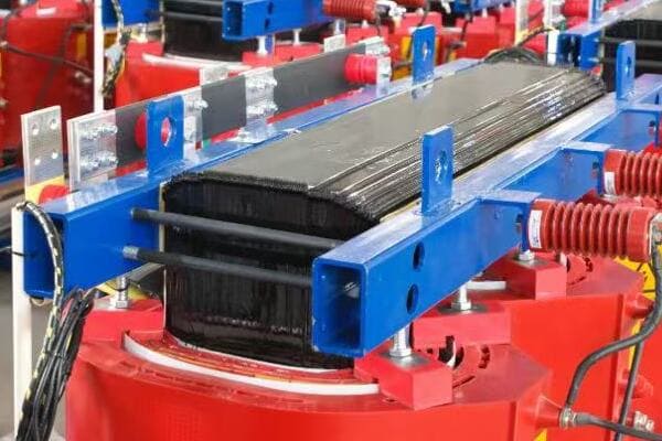
Understanding Transformer Efficiency and Losses
Let’s delve into the key aspects of transformer efficiency and the types of losses:
1. Core Losses
These occur in the transformer’s magnetic core:
- Hysteresis losses due to magnetization reversal
- Eddy current losses from induced currents in the core
I remember a project where we were tasked with upgrading an old transformer. By replacing the core with a more advanced silicon steel alloy, we reduced core losses by almost 30%. The energy savings over time were substantial.
2. Copper Losses
Also known as I²R losses, these occur in the windings:
- Caused by electrical resistance in the copper windings
- Increase with the square of the current
3. Stray Losses
Additional losses that include:
- Leakage flux
- Eddy currents in structural parts
4. Efficiency Calculation
Transformer efficiency is calculated as:
Efficiency = (Output Power / Input Power) × 100%
Here’s a table summarizing the types of losses and their characteristics:
| Loss Type | Cause | Mitigation Strategies |
|---|---|---|
| Hysteresis Loss | Magnetic domain alignment | Use of low-loss core materials |
| Eddy Current Loss | Induced currents in core | Laminated core design |
| Copper Loss | Winding resistance | Larger wire gauge, better cooling |
| Stray Loss | Leakage flux, structural eddy currents | Improved design, shielding |
In my experience, managing transformer losses is a constant balancing act. I once worked on a project for a large data center where energy efficiency was paramount. We implemented a combination of amorphous metal cores and copper windings with optimized cross-sections. The result was a transformer with efficiency exceeding 99%, but it came at a higher initial cost. The challenge was to justify this cost through long-term energy savings.
One fascinating aspect of transformer efficiency is how it varies with load. Most transformers are designed to be most efficient at around 50-70% of their rated load. In a recent project for a variable load application, we designed a transformer with multiple tap settings that could adjust its turns ratio based on the load. This allowed us to maintain high efficiency across a wider range of operating conditions.
Temperature management is crucial in minimizing losses. As transformers heat up, their efficiency typically decreases. In a high-power transformer project, we implemented an advanced cooling system using a combination of oil circulation and external radiators. This not only improved efficiency but also extended the transformer’s lifespan by reducing thermal stress on the insulation.
The impact of harmonics on transformer efficiency is an increasingly important consideration, especially in environments with many non-linear loads. I worked on a project for an industrial plant where harmonic currents were causing excessive heating in the transformer. We solved this by implementing a K-rated transformer design, which included additional capacity to handle harmonic loads without excessive losses.
Efficiency standards for transformers have become more stringent over the years. In a recent project to upgrade a utility’s distribution transformers, we had to navigate complex efficiency regulations. We ended up using a combination of advanced core materials and optimized winding designs to meet and exceed these standards, resulting in significant energy savings across the network.
The trend towards higher frequency power systems, particularly in renewable energy and electric vehicle applications, presents new challenges in transformer efficiency. I’m currently involved in research on high-frequency transformer designs that use nanocrystalline core materials. These materials offer extremely low losses at high frequencies, opening up new possibilities for compact and efficient power conversion.
Lastly, the concept of total cost of ownership is becoming increasingly important in transformer selection. In a recent consultation for a large industrial client, we conducted a detailed analysis comparing the initial costs of standard and high-efficiency transformers against their lifetime energy savings. This approach helped the client make an informed decision, opting for a more efficient transformer that, while more expensive upfront, offered substantial savings over its operational life.
Understanding and managing transformer efficiency and losses is crucial in modern power systems. As we push for more energy-efficient solutions and integrate more complex power sources and loads into our grids, the role of efficient transformers becomes ever more critical. By continually innovating in materials, design, and cooling technologies, we can create transformers that not only meet current needs but also pave the way for a more energy-efficient future.
Real-World Example: From Grid to Home?
Have you ever wondered about the journey electricity takes from a power plant to your home? This journey involves multiple transformers, each playing a crucial role. But how exactly does this process work, and why are so many voltage changes necessary?
The journey of electricity from grid to home involves multiple transformer stages. It starts with step-up transformers at power plants, increasing voltage for long-distance transmission. Substations use step-down transformers to reduce voltage for local distribution. Finally, pole-mounted or pad-mounted transformers further step down the voltage for safe use in homes and businesses.
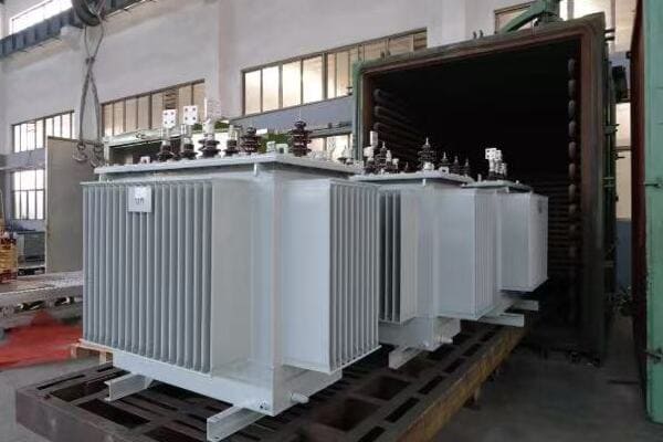
Tracing the Path of Electricity from Grid to Home
Let’s follow the journey of electricity and the transformers involved:
1. Power Generation
At the power plant:
- Generators produce electricity at medium voltage (e.g., 15-25 kV)
- Step-up transformers increase voltage for transmission (e.g., to 345 kV or higher)
I once visited a large hydroelectric plant and was amazed by the massive step-up transformers. Seeing how they could take the generator’s output and boost it to hundreds of thousands of volts for long-distance transmission was truly impressive.
2. Transmission
Long-distance power lines:
- Carry high-voltage electricity over great distances
- Minimize power losses due to lower current at high voltage
3. Substation Step-Down
At local substations:
- Large step-down transformers reduce voltage (e.g., from 345 kV to 69 kV)
- Prepare power for distribution to local areas
4. Distribution
Local power lines:
- Carry medium voltage electricity (e.g., 12 kV or 24 kV)
- Supply power to neighborhoods and business districts
5. Final Step-Down
Near end-users:
- Pole-mounted or pad-mounted transformers
- Reduce voltage to usable levels (e.g., 240/120 V for homes)
Here’s a table showing typical voltage levels in the power distribution chain:
| Stage | Typical Voltage | Transformer Type |
|---|---|---|
| Generation | 15-25 kV | Step-up |
| Transmission | 345-765 kV | – |
| Subtransmission | 69-138 kV | Step-down |
| Distribution | 12-24 kV | Step-down |
| Residential Use | 240/120 V | Step-down |
In my career, I’ve had the opportunity to work on various stages of this power journey. One particularly interesting project involved upgrading a substation that served as a crucial link between the high-voltage transmission network and the local distribution grid. We replaced an aging 100 MVA transformer with a new 150 MVA unit, significantly increasing the substation’s capacity to meet growing local demand.
The efficiency considerations at each stage of this journey are fascinating. In transmission, we use extremely high voltages to minimize losses over long distances. I once calculated that increasing the transmission voltage from 345 kV to 500 kV on a particular line reduced power losses by almost 40%. This efficiency gain had to be balanced against the increased cost of higher voltage equipment.
Reliability is a critical factor, especially at the substation level. In a recent project, we implemented a redundant transformer setup at a critical substation. This involved installing two 60 MVA transformers instead of a single 100 MVA unit. While slightly less efficient, this configuration provided crucial backup in case of transformer failure, significantly improving the reliability of the local power supply.
The final step-down to residential voltage is often overlooked but is crucial for safety and appliance compatibility. I worked on a project to upgrade the distribution transformers in an older neighborhood. By replacing outdated units with modern, more efficient models, we not only improved power quality for residents but also reduced overall system losses.
Smart grid technologies are increasingly being integrated into this power journey. In a recent project, we installed smart transformers at various points in the distribution network. These transformers could communicate real-time load information, helping to balance power flow and quickly identify potential issues before they led to outages.
The integration of renewable energy sources is adding new complexity to this traditional power flow. In a solar farm project, we had to design a system that could feed power back into the grid. This involved careful consideration of bidirectional power flow and voltage regulation to ensure seamless integration with the existing infrastructure.
Lastly, the trend towards electric vehicle adoption is beginning to impact the final stages of power distribution. In a recent residential development project, we had to upsize the local distribution transformers to handle the additional load from EV charging. This required careful load forecasting and consideration of future growth in EV adoption.
Understanding the journey of electricity from grid to home highlights the crucial role transformers play at every stage. From the massive units at power plants to the small pole-mounted transformers in our neighborhoods, each plays a vital part in ensuring we have safe, reliable power in our homes and businesses. As our power needs evolve, with increasing renewable integration and changing consumption patterns, the transformer technology at each stage of this journey will continue to adapt and improve.
Conclusion
Transformers are essential in power systems, enabling efficient voltage conversion for transmission and distribution. They work through electromagnetic induction, with primary and secondary windings around a magnetic core. Understanding their operation, efficiency, and role in power distribution is crucial for maintaining and improving our electrical infrastructure.
Free CHBEB Transformer Catalog Download
Get the full range of CHBEB transformers in one catalog.
Includes oil-immersed, dry-type, pad-mounted, and custom solutions.
Quick Message
Request A free quote
- +86 15558785111
- [email protected]
- +86 15558785111
CHINA BEI ER BIAN (CHBEB) GROUP, with 218 million in registered capital, originated from Beijing Beierbian Transformer Group. Headquartered in Beijing for R&D, it operates major production bases in Nanjing and Yueqing, producing high-quality products.
No 3,RongJing East Road,BeiJing Economic Technological Development Area,BeiJing,China
No 7️Xiangfeng Road,Jiangning,NanJing,JiangSu,China
No.211, Wei 16 Road, Industrial Zone, Yueqing, Wenzhou, Zhejiang, China.
XiangYang Industrial Zone ,YueQing,WenZhou,ZheJiang,China
- [email protected]
- +86 13057780111
- +86 13057780111
- +86 15558785111
Copyright © Bei Er Bian Group


