Have you ever wondered how electricity from power plants safely reaches your home? The answer lies in a crucial device: the electrical transformer. Without it, our modern electrical grid wouldn’t exist.
Electrical transformers work by using electromagnetic induction to transfer energy between two or more circuits. They change voltage levels, making power transmission efficient and electricity use safe. This process involves core components like coils and an iron core, and follows specific mathematical principles.
As someone who has worked in the power industry for years, I’ve seen firsthand how transformers shape our electrical systems. Let’s dive deeper into the world of electrical transformers and explore their fascinating workings by answering five key questions.
The Fundamental Principle: How Electromagnetic Induction Powers Transformers?
Have you ever been curious about the magic behind transformers? How can they change voltage levels so efficiently? The answer lies in a fascinating principle: electromagnetic induction.
Electromagnetic induction is the process by which a changing magnetic field creates an electric current in a nearby conductor. In transformers, this principle allows energy to be transferred between circuits, enabling voltage transformation without direct electrical connection.
Let me explain this fascinating principle and how it applies to transformers, based on my experience in the field.
The Discovery of Electromagnetic Induction
Michael Faraday discovered electromagnetic induction in 1831. This discovery changed the world of electricity forever. Here’s how it works:
- A changing magnetic field creates an electric field.
- This electric field can create a current in a nearby conductor.
How Electromagnetic Induction Works in Transformers
In a transformer, we use electromagnetic induction to transfer energy between two coils. Here’s the process:
- Primary Coil: We apply an alternating current to this coil.
- Changing Magnetic Field: The alternating current creates a changing magnetic field.
- Iron Core: This concentrates and directs the magnetic field.
- Secondary Coil: The changing magnetic field induces a voltage in this coil.
Faraday’s Law of Induction
Faraday’s Law is the mathematical expression of electromagnetic induction. It states that the induced electromotive force (EMF) in a circuit is proportional to the rate of change of magnetic flux through the circuit. In equation form:
EMF = -N * (dΦ/dt)
Where:
- EMF is the induced electromotive force
- N is the number of turns in the coil
- dΦ/dt is the rate of change of magnetic flux
Practical Applications in Transformers
| Component | Role in Electromagnetic Induction |
|---|---|
| Primary Coil | Creates changing magnetic field |
| Iron Core | Concentrates and directs magnetic field |
| Secondary Coil | Experiences induced voltage |
In my work with transformers, I’ve seen how understanding these principles is crucial for design and troubleshooting:
- Core Material: We choose materials with high magnetic permeability to enhance the magnetic field.
- Coil Design: The number of turns in each coil directly affects the voltage transformation.
- Frequency Considerations: The frequency of the AC supply affects the rate of change of the magnetic field.
Understanding electromagnetic induction is key to grasping how transformers work. It’s amazing how this simple principle, discovered almost two centuries ago, still forms the basis of our modern electrical grid.
Anatomy of a Transformer: Understanding Core Components and Their Functions?
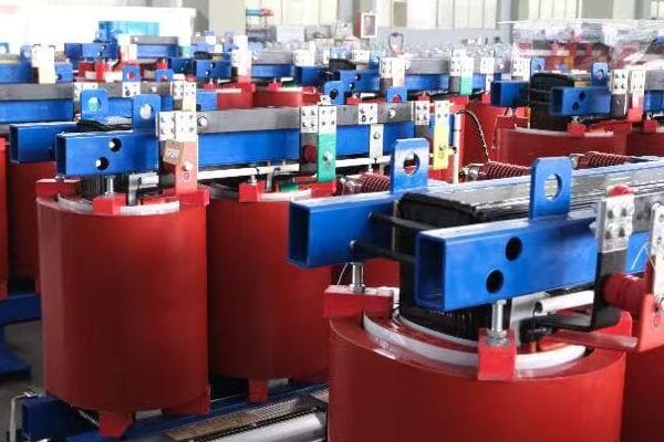
Have you ever wondered what’s inside a transformer? These devices may look simple from the outside, but their internal structure is key to their function.
A transformer consists of three main components: the primary coil, the secondary coil, and the iron core. The primary coil receives the input voltage, the secondary coil outputs the transformed voltage, and the iron core enhances the magnetic coupling between the coils.
Let me take you on a tour of a transformer’s anatomy, based on my years of experience working with these devices.
The Primary Coil: Where It All Begins
The primary coil is where we input the electrical energy. Here’s what you need to know:
- Function: It receives the input voltage and creates a changing magnetic field.
- Construction: It’s made of insulated copper wire wound around one leg of the iron core.
- Turns: The number of turns in this coil determines the input voltage rating.
The Secondary Coil: Where Transformation Happens
The secondary coil is where we get our transformed voltage. Here are its key features:
- Function: It receives the changing magnetic field and produces the output voltage.
- Construction: Like the primary, it’s made of insulated copper wire on the iron core.
- Turns: The number of turns here, compared to the primary, determines the voltage change.
The Iron Core: The Magnetic Highway
The iron core is crucial for efficient operation. Here’s why:
- Function: It provides a path for the magnetic field, increasing the coupling between coils.
- Material: Usually made of laminated silicon steel to reduce eddy current losses.
- Types: Can be core-type (coils around outside) or shell-type (coils inside).
Additional Components for Efficiency and Safety
While the coils and core are the main parts, transformers often have additional components:
- Insulation: Prevents short circuits between turns and layers.
- Cooling System: Oil or air cooling to manage heat from losses.
- Tap Changer: Allows for small adjustments in turns ratio.
- Bushings: Insulated passages for connections to enter/exit the transformer.
Comparison of Transformer Components
| Component | Function | Material | Key Consideration |
|---|---|---|---|
| Primary Coil | Receives input voltage | Copper wire | Number of turns |
| Secondary Coil | Outputs transformed voltage | Copper wire | Turns ratio with primary |
| Iron Core | Enhances magnetic coupling | Silicon steel | Lamination for loss reduction |
| Insulation | Prevents short circuits | Various | Dielectric strength |
| Cooling System | Manages heat | Oil or air | Efficiency of heat dissipation |
In my work designing transformers, I’ve learned that the relationship between these components is crucial. Here are some key considerations:
- Core Size: Must be large enough to handle the magnetic flux without saturation.
- Wire Gauge: Must be thick enough to handle the current without overheating.
- Insulation: Must withstand the voltage stress between turns and layers.
- Cooling: Must be adequate to dissipate heat and maintain efficiency.
Understanding the anatomy of a transformer is crucial for designing efficient and reliable power systems. Each component plays a vital role, and the interplay between them determines the transformer’s performance.
Voltage and Current Transformation: The Mathematics Behind the Magic?
Have you ever wondered how transformers can change voltage and current levels so precisely? The answer lies in some fascinating mathematical relationships.
Transformers change voltage and current levels based on the ratio of turns in their primary and secondary coils. The voltage ratio is directly proportional to the turns ratio, while the current ratio is inversely proportional. This relationship is governed by the principle of conservation of energy.
Let me break down the mathematics behind transformer operation, based on my experience in the field.
The Transformer Equation
The fundamental relationship in a transformer is described by the transformer equation:
Vs / Vp = Ns / Np
Where:
- Vs = Secondary Voltage
- Vp = Primary Voltage
- Ns = Number of turns in Secondary Coil
- Np = Number of turns in Primary Coil
This equation shows that the ratio of voltages is equal to the ratio of turns in the coils.
Current Transformation
The current transformation follows an inverse relationship:
Ip / Is = Ns / Np
Where:
- Ip = Primary Current
- Is = Secondary Current
This relationship ensures that power is conserved (ignoring losses).
Power Conservation
In an ideal transformer, the power in equals the power out:
Vp Ip = Vs Is
This equation is crucial for understanding how transformers maintain energy balance.
Practical Applications
Here’s how these equations play out in real-world scenarios:
| Scenario | Turns Ratio (Ns/Np) | Voltage Ratio (Vs/Vp) | Current Ratio (Ip/Is) |
|---|---|---|---|
| Step-Up | > 1 | > 1 | < 1 |
| Step-Down | < 1 | < 1 | > 1 |
| Isolation | = 1 | = 1 | = 1 |
In my work, I’ve seen how these mathematical relationships guide transformer design:
- Voltage Requirements: We determine the turns ratio based on the required voltage transformation.
- Current Capacity: We size the wire gauge based on the expected current in each coil.
- Power Rating: We ensure the transformer can handle the required power transfer.
Real-World Considerations
While these equations describe ideal transformers, real-world devices have some deviations:
- Losses: Core losses and copper losses reduce efficiency.
- Leakage Inductance: Not all magnetic flux links both coils.
- Winding Resistance: Causes voltage drop and power loss.
Understanding these mathematical relationships is key to designing and using transformers effectively. It’s fascinating how these simple equations govern devices that are so crucial to our modern electrical systems.
Efficiency in Action: Factors Affecting Transformer Performance?
Have you ever wondered why some transformers perform better than others? The key lies in understanding the factors that affect transformer efficiency.
Transformer efficiency is influenced by several factors including core losses, copper losses, operating temperature, and load conditions. High-efficiency transformers minimize these losses through careful design, material selection, and proper operation.
Let me share some insights from my experience about the factors that affect transformer performance and how we can optimize them.
Core Losses: The Silent Energy Drain
Core losses, also known as iron losses, occur in the transformer’s magnetic core. They consist of two main types:
- Hysteresis Loss: Energy lost in repeatedly magnetizing and demagnetizing the core.
- Eddy Current Loss: Energy lost due to currents induced in the core material.
To minimize core losses:
- We use high-quality silicon steel for the core.
- We laminate the core to reduce eddy currents.
- We optimize the core design to reduce the magnetic path length.
Copper Losses: The Resistance Factor
Copper losses, or I²R losses, occur due to the resistance of the transformer windings. They increase with the square of the current.
To reduce copper losses:
- We use larger wire gauges to reduce resistance.
- We design for shorter winding lengths where possible.
- We use parallel conductors for high-current windings.
Temperature Effects: Keeping Cool Under Pressure
Operating temperature significantly affects transformer efficiency. Higher temperatures increase resistance and thus copper losses.
To manage temperature:
- We use efficient cooling systems (oil or air cooling).
- We design for optimal heat dissipation.
- We monitor temperature during operation to prevent overheating.
Load Conditions: Finding the Sweet Spot
Transformers are most efficient at their rated load. Both underloading and overloading can reduce efficiency.
To optimize for load conditions:
- We size transformers appropriately for their expected load.
- We use tap changers to adjust for varying load conditions.
- We implement load management strategies in power systems.
Comparison of Efficiency Factors
| Factor | Cause | Mitigation Strategy |
|---|---|---|
| Core Losses | Magnetic core cycling | High-quality core material, lamination |
| Copper Losses | Winding resistance | Larger wire gauge, shorter windings |
| Temperature | Heat generation | Efficient cooling, thermal design |
| Load Conditions | Mismatch with rated load | Proper sizing, tap changing |
In my work designing and optimizing transformers, I’ve learned that balancing these factors is crucial. Here are some real-world considerations:
- Cost vs. Efficiency: Higher efficiency often means higher initial cost. We need to balance this with long-term energy savings.
- Size and Weight: Improving efficiency often increases size and weight. This can be a challenge in space-constrained applications.
- Environmental Conditions: Factors like altitude, ambient temperature, and humidity can affect transformer performance.
- Harmonics: In modern power systems, harmonic currents can significantly impact transformer efficiency.
Understanding and optimizing these factors is key to designing high-performance transformers. It’s a constant challenge to balance efficiency, cost, size, and reliability, but it’s crucial for creating sustainable and effective power systems.
From Theory to Practice: Real-World Applications of Transformer Principles?
Have you ever wondered how the principles of transformer operation translate into real-world applications? The theory we’ve discussed comes to life in a wide range of practical uses.
Transformer principles find applications in various fields, from power distribution to electronics and renewable energy. They enable efficient power transmission, voltage conversion in electronic devices, and integration of renewable sources into the grid.
Let me share some examples from my experience of how transformer principles are applied in different sectors.
Power Distribution: The Backbone of Our Electrical Grid
In power distribution, transformers play a crucial role:
- Step-Up Transformers: At power plants, these increase voltage for long-distance transmission.
- Step-Down Transformers: At substations, these reduce voltage for local distribution.
- Pole-Mounted Transformers: These further step down voltage for residential use.
Electronics: Enabling Our Digital World
In electronics, transformers are essential components:
- Power Supplies: They convert high voltage AC to low voltage DC for electronic devices.
- Audio Equipment: Output transformers in tube amplifiers shape the sound quality.
- Isolation Transformers: These provide safety in medical and test equipment.
Industrial Applications: Powering Manufacturing
Industry relies heavily on transformer technology:
- Arc Welding: Welding transformers provide the high current needed for welding.
- Induction Furnaces: Transformers supply power for melting metal in foundries.
- Variable Frequency Drives: These use transformers to control motor speeds.
Renewable Energy: Integrating Clean Power
Transformers are crucial in renewable energy systems:
- Wind Farms: They step up voltage from wind turbines for grid connection.
- Solar Inverters: Transformers help convert DC from solar panels to AC for the grid.
- Smart Grids: Advanced transformers enable bidirectional power flow in smart grids.
Comparison of Transformer Applications
| Application | Transformer Type | Key Function | Typical Size Range |
|---|---|---|---|
| Power Transmission | Step-Up | Increase voltage for transmission | 100 MVA – 1000 MVA |
| Local Distribution | Step-Down | Reduce voltage for safe use | 5 MVA – 100 MVA |
| Electronic Devices | Small SMPS Transformers | Convert to low voltage DC | 1 VA – 1 kVA |
| Industrial Welding | Welding Transformers | Provide high current at low voltage | 5 kVA – 50 kVA |
| Wind Farms | Wind Turbine Transformers | Step up voltage for grid connection | 1 MVA – 10 MVA |
In my work across these sectors, I’ve encountered various challenges and innovations:
- Size and Weight Reduction: In electronics, we’re constantly working to make transformers smaller and lighter.
- Efficiency Improvements: In power distribution, even small efficiency gains can lead to significant energy savings.
- High-Frequency Operation: In switch-mode power supplies, transformers operate at high frequencies for better efficiency.
- Smart Transformers: In modern grids, we’re developing transformers with communication and control capabilities.
Understanding these real-world applications helps bridge the gap between theory and practice. It’s fascinating to see how the basic principles of electromagnetic induction, discovered nearly two centuries ago, continue to shapeour modern world in so many ways.
Emerging Applications: The Future of Transformer Technology
As technology evolves, new applications for transformers are emerging:
- Electric Vehicle Charging: Fast-charging stations use transformers to provide high-power DC charging.
- Solid-State Transformers: These combine power electronics with traditional transformer principles for more flexible power control.
- Quantum Transformers: Research is ongoing into using quantum effects to create more efficient transformers.
Challenges in Real-World Applications
In my experience, applying transformer principles in the real world comes with several challenges:
- Harmonics: Modern electronic loads can introduce harmonics, which transformers must be designed to handle.
- Extreme Environments: Transformers in offshore wind farms or desert solar plants must withstand harsh conditions.
- Size Constraints: In urban environments or portable devices, space for transformers is often limited.
- Reliability: In critical applications like hospitals or data centers, transformer reliability is paramount.
Innovations Addressing Real-World Challenges
To address these challenges, the industry is constantly innovating:
- Advanced Materials: New core materials like amorphous metals are reducing losses.
- Digital Twins: Virtual models of transformers help predict and optimize performance.
- Biodegradable Insulating Fluids: These are replacing traditional transformer oil for better environmental safety.
- IoT Integration: Sensors and connectivity are enabling predictive maintenance of transformers.
Understanding these real-world applications and challenges is crucial for anyone working with transformer technology. It’s not just about the theory – it’s about how we apply that theory to solve real problems and create efficient, reliable power systems.
Conclusion
Electrical transformers are fascinating devices that work on the principle of electromagnetic induction. They play a crucial role in voltage transformation, power distribution, and various applications across industries. Understanding their operation is key to advancing our electrical systems.
