How Does Power Transformer Work: A Comprehensive Guide for Beginners?
Have you ever wondered how electricity travels from power plants to your home? The answer lies in power transformers, but many people don’t know how they work.
Power transformers are devices that transfer electrical energy between two circuits using electromagnetic induction. They change voltage levels without changing the frequency, allowing for efficient power transmission and distribution across long distances.
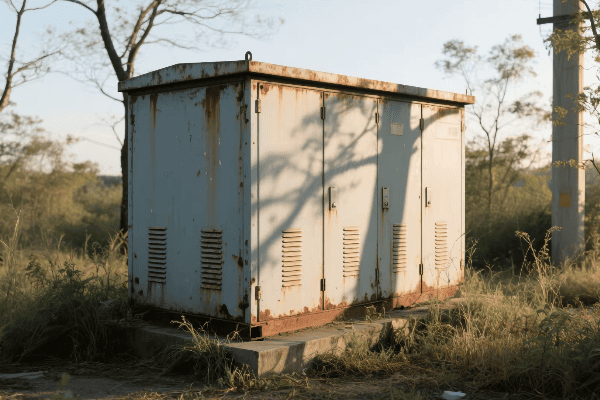
In this guide, I’ll break down the workings of power transformers. I’ve spent years in the power industry, and I’m excited to share my knowledge with you.
What Are the Basic Principles of Electromagnetic Induction in Power Transformers?
Electromagnetic induction might sound complex, but it’s the foundation of how power transformers work. I remember being fascinated by this concept when I first learned about it.
Electromagnetic induction in power transformers involves a changing magnetic field in one coil inducing a voltage in another coil. This principle allows transformers to transfer energy between circuits without direct electrical connection.
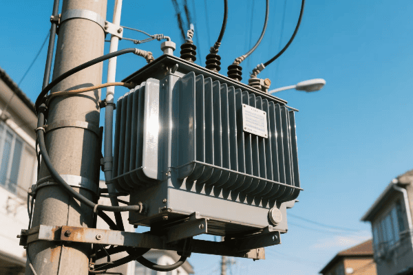
Let’s dive deeper into the principles of electromagnetic induction in power transformers:
Faraday’s Law of Induction
Faraday’s Law is the key to understanding how transformers work. It states that a changing magnetic field induces a voltage in a conductor. Here’s how it applies to transformers:
- Primary Coil: When AC current flows through this coil, it creates a changing magnetic field.
- Magnetic Core: This field is concentrated in the core.
- Secondary Coil: The changing field in the core induces a voltage in this coil.
I once explained this to a group of students using a simple experiment with two coils and a magnet. Their eyes lit up when they saw the meter move as I moved the magnet through one coil.
Mutual Induction
Mutual induction is the process where two coils interact through their magnetic fields. In a transformer:
| Primary Coil | Secondary Coil |
|---|---|
| Creates magnetic field | Experiences induced voltage |
| Receives input power | Delivers output power |
| Determines input current | Determines output voltage |
This interaction is what allows transformers to transfer energy between circuits without direct electrical contact.
Lenz’s Law
Lenz’s Law explains the direction of induced current in the secondary coil. It states that the induced current will create a magnetic field that opposes the change in the original field. This law ensures that:
- The induced voltage in the secondary coil has the correct polarity.
- Energy is conserved in the transformation process.
Understanding Lenz’s Law helped me grasp why transformers work the way they do, and why they’re so efficient at transferring energy.
How Do Primary and Secondary Windings Interact to Transfer Energy in a Power Transformer?
The interaction between primary and secondary windings is like a well-choreographed dance. It’s this interaction that makes power transformers so effective at energy transfer.
Primary and secondary windings in a power transformer interact through a shared magnetic field. The primary winding creates a changing magnetic flux, which induces a voltage in the secondary winding. This process transfers energy between the two circuits.

Let’s explore this interaction in more detail:
Primary Winding Function
The primary winding is where it all starts. Here’s what happens:
- AC Input: Alternating current from the power source enters the primary winding.
- Magnetic Field Generation: This current creates a changing magnetic field.
- Flux Linkage: The magnetic field links with the secondary winding through the core.
I remember working on a transformer design where we had to carefully calculate the number of turns in the primary winding to match the input voltage. It’s a crucial step in transformer design.
Secondary Winding Response
The secondary winding responds to the magnetic field from the primary:
- Induced Voltage: The changing magnetic field induces a voltage in the secondary winding.
- Current Flow: If a load is connected, current flows in the secondary circuit.
- Power Transfer: Electrical energy is effectively transferred from primary to secondary.
Turns Ratio and Voltage Transformation
The ratio of turns in the primary and secondary windings determines the voltage transformation:
| Turns Ratio | Voltage Transformation |
|---|---|
| Np > Ns | Step-down transformer |
| Np < Ns | Step-up transformer |
| Np = Ns | Isolation transformer |
Where Np is the number of primary turns and Ns is the number of secondary turns.
This relationship is crucial. I once worked on a project where we needed to step up voltage for long-distance transmission. By carefully designing the turns ratio, we were able to achieve the exact voltage increase needed.
Energy Conservation
Despite the voltage change, energy is conserved in an ideal transformer:
- Power In = Power Out
- Vp Ip = Vs Is
Where Vp and Ip are primary voltage and current, and Vs and Is are secondary voltage and current.
In practice, there are small losses due to factors like core losses and winding resistance. But modern transformers are incredibly efficient, often above 98%.
What Role Does the Core Play in the Functioning of a Power Transformer?
The core of a power transformer might not be visible from the outside, but it’s absolutely crucial to its operation. I’ve seen firsthand how the right core design can make or break a transformer’s performance.
The core in a power transformer provides a low-reluctance path for magnetic flux, concentrating the magnetic field created by the primary winding. This enhances the coupling between primary and secondary windings, improving efficiency and reducing losses.
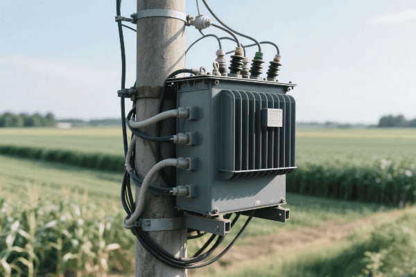
Let’s delve into the core’s role in more detail:
Magnetic Flux Concentration
The core’s primary function is to concentrate magnetic flux:
- Low Reluctance Path: The core provides an easy path for magnetic flux.
- Flux Containment: It keeps the magnetic field contained, reducing stray fields.
- Coupling Enhancement: This improves the coupling between primary and secondary windings.
I once worked on a project comparing different core materials. The difference in performance was striking. A high-quality silicon steel core significantly outperformed older materials.
Core Materials
The choice of core material is crucial:
| Material | Advantages | Disadvantages |
|---|---|---|
| Silicon Steel | Low core losses, high permeability | Saturation at high flux densities |
| Amorphous Metal | Very low core losses | Higher cost, more difficult to manufacture |
| Ferrite | Good for high-frequency applications | Lower saturation flux density |
Each material has its place. For large power transformers, silicon steel is still the go-to choice due to its balance of performance and cost.
Core Designs
There are several common core designs:
- Shell Type: Windings surrounded by core material
- Core Type: Core surrounded by windings
- Toroidal: Donut-shaped core with windings wound around it
Each design has its advantages. I’ve found that shell type cores often work well for large power transformers, while toroidal cores are great for smaller, high-efficiency applications.
Laminations and Eddy Current Reduction
Core laminations are thin sheets of magnetic material stacked together. They serve a crucial purpose:
- Eddy Current Reduction: Laminations break up the core, reducing eddy current losses.
- Heat Reduction: Less eddy current means less heat generation.
- Efficiency Improvement: This results in higher overall transformer efficiency.
I remember a project where we switched from thick laminations to thinner ones. The reduction in core losses was significant, leading to a measurable increase in efficiency.
Core Saturation
Core saturation is a phenomenon that transformer designers must be aware of:
- Definition: When the core can’t support any more magnetic flux
- Effects: Increased magnetizing current, reduced efficiency, potential overheating
- Prevention: Proper core sizing and material selection
I once troubleshooted a transformer that was overheating. It turned out the core was undersized for the application, leading to saturation. Replacing it with a larger core solved the problem.
How Do Power Transformers Manage Voltage Step-Up and Step-Down Processes?
Voltage transformation is the primary function of power transformers. It’s fascinating how these devices can change voltage levels so efficiently. I’ve designed transformers for both step-up and step-down applications.
Power transformers manage voltage step-up and step-down processes through the ratio of turns in their primary and secondary windings. A higher number of secondary turns results in step-up, while fewer secondary turns result in step-down.
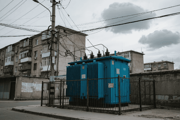
Let’s explore this process in more detail:
Turns Ratio Principle
The turns ratio is the key to voltage transformation:
- Step-Up: Secondary turns > Primary turns
- Step-Down: Secondary turns < Primary turns
- Isolation: Secondary turns = Primary turns
The voltage ratio equals the turns ratio in an ideal transformer:
Vs / Vp = Ns / Np
Where Vs and Vp are secondary and primary voltages, and Ns and Np are secondary and primary turns.
Step-Up Transformers
Step-up transformers increase voltage. They’re used in:
- Power Generation: To increase generator voltage for transmission
- Renewable Energy: To boost voltage from solar or wind farms for grid connection
- Electronics: In devices like inverters or boost converters
I once worked on a step-up transformer for a wind farm. We had to carefully design it to handle the variable input from the wind turbines while providing a stable high-voltage output for the grid.
Step-Down Transformers
Step-down transformers decrease voltage. They’re used in:
- Distribution: To reduce transmission voltage for local distribution
- Industrial Applications: To provide appropriate voltage for machinery
- Consumer Electronics: In power adapters for devices
Step-down transformers are crucial in bringing high transmission voltages down to levels safe for homes and businesses. I’ve designed distribution transformers that step down voltage from 11kV to 415V for commercial buildings.
Autotransformers
Autotransformers are a special type that use a single winding for both primary and secondary:
| Advantages | Disadvantages |
|---|---|
| Smaller size | No electrical isolation |
| Lower cost | Limited voltage ratios |
| Higher efficiency | Safety concerns in some applications |
I’ve used autotransformers in projects where size and cost were critical, and isolation wasn’t necessary. They can be very effective in the right applications.
Tap Changers
Tap changers allow for fine-tuning of the voltage ratio:
- Off-Load Tap Changers: Adjusted when the transformer is de-energized
- On-Load Tap Changers: Can be adjusted while the transformer is in operation
These devices are crucial for maintaining stable output voltage despite fluctuations in input voltage or load. I’ve worked with utilities to implement on-load tap changers in their distribution transformers, significantly improving power quality for their customers.
What Are the Key Components of a Power Transformer and Their Functions?
Understanding the components of a power transformer is crucial for anyone working with these devices. Each part plays a vital role in the transformer’s operation. I’ve spent countless hours designing and optimizing these components.
The key components of a power transformer include the core, windings, insulation system, cooling system, and tap changers. Each component contributes to the transformer’s ability to efficiently and safely transform voltage levels.
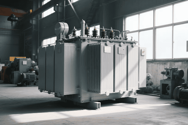
Let’s explore each of these components in detail:
Core
The core is the magnetic heart of the transformer:
- Material: Usually made of silicon steel laminations
- Function: Provides a path for magnetic flux
- Types: Core-type or shell-type designs
I once worked on a project comparing different core designs. We found that the shell-type design provided better magnetic shielding, which was crucial for the sensitive equipment nearby.
Windings
Windings are the electrical part of the transformer:
| Primary Winding | Secondary Winding |
|---|---|
| Connects to power source | Connects to load |
| Creates magnetic field | Experiences induced voltage |
| Determines input current | Determines output voltage |
The design of windings is critical. I remember a project where we redesigned the winding layout to improve cooling. It significantly increased the transformer’s power handling capacity.
Insulation System
The insulation system prevents short circuits and allows for high voltage operation:
- Oil Insulation: Used in large power transformers
- Solid Insulation: Paper or polymer materials
- Gas Insulation: SF6 gas in some special applications
Proper insulation is crucial for safety and longevity. I’ve seen transformers fail due to insulation breakdown, which can be catastrophic.
Cooling System
The cooling system prevents overheating:
- Oil-Immersed Cooling: ONAN, ONAF, OFAF types
- Dry-Type Cooling: Air Natural (AN) or Air Forced (AF)
Choosing the right cooling system depends on the transformer’s size, location, and load profile. I once designed a custom cooling system for a transformer located in an extremely hot climate. It involved a combination of oil circulation and external radiators.
Tap Changers
Tap changers allow for voltage adjustment:
- Off-Load Tap Changers: Adjusted when transformer is de-energized
- On-Load Tap Changers: Can be adjusted during operation
Tap changers are crucial for maintaining stable output voltage. I’ve worked on projects implementing smart tap changers that automatically adjust based on load conditions, significantly improving power quality.
Bushings
Bushings are the connection points between the transformer’s internal wiring and the external electrical system:
- Function: Provide insulated passage for conductors
- Types: Oil-filled, solid, or gas-filled
Proper bushing design is crucial for preventing flashovers. I once investigated a transformer failure that was traced back to a poorly designed bushing. It taught me the importance of every component, no matter how small it might seem.
Tank and Conservator
For oil-filled transformers:
- Tank: Houses the core, windings, and oil
- Conservator: Allows for oil expansion and contraction
These components are crucial for containing the oil and maintaining proper insulation. I’ve been involved in designing transformer tanks that can withstand extreme environmental conditions, from arctic cold to desert heat.
Conclusion
Power transformers are complex devices that rely on electromagnetic induction to transfer and transform electrical energy. Understanding their components and principles is crucial for anyone working in the power industry or studying electrical engineering.
Free CHBEB Transformer Catalog Download
Get the full range of CHBEB transformers in one catalog.
Includes oil-immersed, dry-type, pad-mounted, and custom solutions.
Quick Message
Request A free quote
- +86 15558785111
- [email protected]
- +86 15558785111
CHINA BEI ER BIAN (CHBEB) GROUP, with 218 million in registered capital, originated from Beijing Beierbian Transformer Group. Headquartered in Beijing for R&D, it operates major production bases in Nanjing and Yueqing, producing high-quality products.
No 3,RongJing East Road,BeiJing Economic Technological Development Area,BeiJing,China
No 7️Xiangfeng Road,Jiangning,NanJing,JiangSu,China
No.211, Wei 16 Road, Industrial Zone, Yueqing, Wenzhou, Zhejiang, China.
XiangYang Industrial Zone ,YueQing,WenZhou,ZheJiang,China
- [email protected]
- +86 13057780111
- +86 13057780111
- +86 15558785111
Copyright © Bei Er Bian Group


