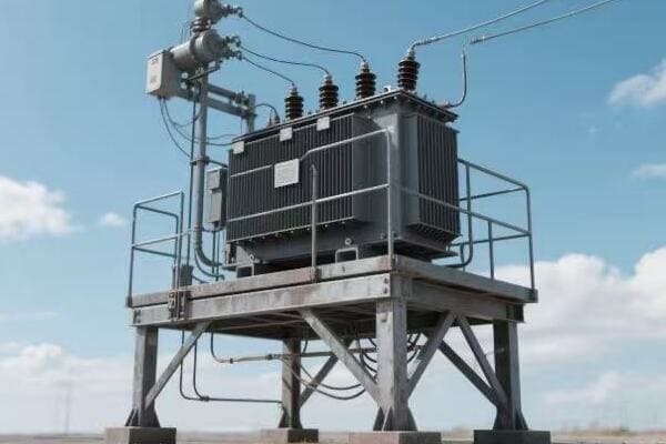
Are you a utility technician struggling to make sense of those complex transformer diagrams? You’re not alone. Many technicians find these blueprints confusing, but mastering them is crucial for your job.
Interpreting pad mounted transformer diagrams is a vital skill for utility technicians. It involves understanding symbols, electrical connections, and component layouts. This knowledge is essential for efficient maintenance, troubleshooting, and ensuring safety in the field.

In this article, I’ll guide you through the essentials of reading and interpreting pad mounted transformer diagrams. Whether you’re a seasoned pro or new to the field, you’ll find valuable insights to enhance your skills and boost your confidence on the job.
Transformer Diagram Basics: Your First Steps in Reading Electrical Blueprints?
Have you ever felt lost when looking at a transformer diagram? Don’t worry, we’ve all been there. The key is to start with the basics and build your knowledge step by step.
Understanding transformer diagram basics involves familiarizing yourself with the layout, common symbols, and basic electrical concepts. Key elements include the transformer core, windings, bushings, and connection points. Mastering these fundamentals is crucial for accurate interpretation and effective field work.
Let’s break down the fundamental elements of a transformer diagram:
The Big Picture: Understanding Diagram Layout
Before diving into details, it’s important to grasp the overall structure of a transformer diagram.
Key Layout Elements:
- Title block with transformer specifications
- Main body showing internal components
- Connection diagrams for primary and secondary sides
- Legend explaining symbols and abbreviations
Core Components: The Heart of the Transformer
The core and windings are central to any transformer diagram.
Essential Core Elements:
- Core representation (usually a rectangle)
- Primary winding symbols
- Secondary winding symbols
- Magnetic flux path indications
Connection Points: Where Power Flows
Understanding how power enters and exits the transformer is crucial.
Important Connections:
- High voltage bushings
- Low voltage bushings
- Ground connections
- Tap changer points
Auxiliary Systems: Supporting the Main Function
Don’t overlook the supporting components in the diagram.
Common Auxiliary Elements:
- Cooling system representations
- Temperature monitoring points
- Pressure relief devices
- Oil level indicators
| Diagram Element | Purpose | Typical Representation |
|---|---|---|
| Core | Shows transformer’s magnetic center | Rectangle or E-I shape |
| Windings | Indicates voltage transformation | Circular or zigzag lines |
| Bushings | Represents power entry/exit points | Circles or ovals |
| Auxiliary Systems | Shows supporting components | Various symbols |
I remember my first encounter with a pad mounted transformer diagram. It was during my early days as a utility technician, and I was tasked with performing routine maintenance on a residential unit. As I unfolded the diagram, I felt overwhelmed by the maze of lines and symbols before me.
Determined to understand, I started by focusing on the title block. This provided crucial information about the transformer’s capacity and voltage ratings. It was like finding the legend on a map – suddenly, I had a reference point to start my journey.
Next, I turned my attention to the main body of the diagram. The large rectangle in the center, I learned, represented the transformer’s core. Surrounding it were lines symbolizing the windings. It was fascinating to see how these simple shapes could represent such complex electrical components.
One challenge I faced was understanding the connection points. The diagram showed numbered terminals, but relating these to the physical transformer wasn’t immediately obvious. I found that tracing the lines from these points to the windings helped me visualize the actual connections.
A breakthrough moment came when I discovered the importance of the diagram’s orientation. The top view representation didn’t match what I was seeing in front of me until I realized I needed to mentally rotate the diagram. This simple adjustment made a world of difference in relating the blueprint to the real-world transformer.
As I became more comfortable with reading the diagram, I started to appreciate its value. During one maintenance check, I noticed a discrepancy between the diagram and the actual transformer connections. This discovery led to the identification of an incorrectly wired component, potentially preventing a major failure.
Over time, I developed a systematic approach to reading these diagrams. I always start with the title block, then move to the core and windings, followed by the connection points and auxiliary systems. This method has served me well, allowing me to quickly grasp the essential information even in complex diagrams.
One aspect that took some time to master was understanding the scale. In one instance, I misjudged the size of a replacement part based on the diagram, only to find it didn’t fit when I arrived on site. This taught me the importance of always checking the scale notation and using it to calculate actual dimensions.
For newcomers to the field, I always emphasize the importance of the legend or key on the diagram. This often-overlooked section is like a dictionary for the symbols and abbreviations used. Taking the time to study this can save hours of confusion later.
Reading transformer diagrams is a skill that develops with practice. Each diagram I encountered added to my understanding, and soon I was able to quickly interpret even the most complex blueprints. This skill has been invaluable in my career, enabling me to work more efficiently and effectively in the field.
Remember, these diagrams are more than just technical drawings – they’re the roadmap to understanding and maintaining these crucial components of our power infrastructure. With patience and practice, any technician can become proficient in reading and using these essential tools.
Decoding the Symbols: A Beginner’s Guide to Transformer Diagram Language?
Ever felt like you’re trying to decipher an alien language when looking at transformer symbols? You’re not alone. But don’t worry, with a little guidance, you’ll be speaking this language fluently in no time.
Decoding transformer diagram symbols is crucial for accurate interpretation. Common symbols represent components like cores, windings, bushings, and switches. Understanding these symbols and their relationships is key to comprehending the transformer’s structure and function.
Let’s break down the most common symbols you’ll encounter:
Core Symbols: The Transformer’s Foundation
The core is the heart of the transformer, and its symbol is often the starting point in diagram reading.
Common Core Representations:
- Single line rectangle for simple cores
- E-I shape for more complex core structures
- Shaded areas indicating laminated steel
Winding Symbols: The Power Converters
Windings are where the voltage transformation magic happens.
Winding Symbol Types:
- Circular loops for basic representations
- Zigzag lines for more detailed diagrams
- Concentric circles for multiple windings
Bushing Symbols: The Power Gateways
Bushings connect the transformer to the outside world.
Bushing Representations:
- Simple circles or ovals
- Lines extending from circles to indicate connections
- Numbers or letters for identification
Switch and Tap Changer Symbols: Voltage Control
These components allow for voltage adjustment and control.
Switch Symbol Varieties:
- Open and closed contact representations
- Movable contact indicators
- Tap position markers
| Symbol Type | Common Representation | Function |
|---|---|---|
| Core | Rectangle or E-I shape | Shows magnetic circuit |
| Windings | Circles or zigzag lines | Indicates voltage transformation |
| Bushings | Circles with extending lines | Represents external connections |
| Switches | Open/closed contacts | Shows points of control or adjustment |
I vividly remember my first encounter with a complex transformer diagram. It was during a training session early in my career, and the instructor handed out what looked like a cryptic puzzle to the class. As I stared at the jumble of shapes and lines, I felt a mix of confusion and curiosity.
Our instructor began by pointing out the core symbol – a simple rectangle in the center of the diagram. He explained that this represented the transformer’s magnetic core, the foundation of its operation. Suddenly, I had an anchor point in the sea of symbols.
Next, we moved on to the winding symbols. The instructor showed us how the circular loops around the core represented the primary and secondary windings. It was fascinating to see how these simple shapes could represent the complex process of voltage transformation.
One of the most challenging aspects for me was distinguishing between different types of bushing symbols. The diagram used various circle and oval shapes, each with lines extending outward. The instructor explained that these represented the points where power entered and exited the transformer. Understanding this was like finding the ‘doors’ in our symbolic transformer house.
A lightbulb moment came when we discussed switch and tap changer symbols. These small details, often represented by open or closed contact points, were crucial for understanding how the transformer’s voltage could be adjusted. I realized that these symbols were the key to comprehending the transformer’s flexibility in real-world applications.
As we worked through more diagrams, I developed a strategy for tackling new symbols. Whenever I encountered an unfamiliar shape, I’d refer to the diagram’s legend or ask a more experienced colleague. This approach helped me build my ‘symbol vocabulary’ quickly.
One particularly memorable experience was when I encountered a diagram for a three-phase transformer. The complexity of the symbols initially overwhelmed me, but by breaking it down into familiar components – cores, windings, and bushings – I was able to navigate the diagram successfully.
I found that creating my own ‘cheat sheet’ of common symbols was incredibly helpful. I kept this reference guide with me on job sites, and it proved invaluable in those early days. Over time, I needed it less and less as the symbols became second nature.
An interesting challenge arose when I started working with diagrams from different manufacturers. While the basic symbols were often similar, there were subtle differences in how each company represented certain components. This taught me the importance of always checking the specific legend for each diagram I encountered.
For those new to transformer diagrams, I always recommend starting with the basics – core, windings, and bushings. Once you’re comfortable with these, you can move on to more complex symbols like tap changers and auxiliary components.
One technique I found helpful was to sketch out simplified versions of complex diagrams. This process of ‘translating’ detailed symbols into basic shapes helped me better understand the relationships between components.
As I gained experience, I began to appreciate how these symbols weren’t just abstract representations, but a precise language for communicating complex technical information. Mastering this language opened up new levels of understanding in my work with transformers.
Remember, becoming fluent in transformer diagram symbols takes time and practice. Don’t get discouraged if it seems overwhelming at first. With each diagram you study, your comprehension will improve, and soon you’ll be reading these blueprints as easily as a book.
The ability to decode transformer symbols is more than just a technical skill – it’s a key that unlocks a deeper understanding of how our power systems work. As you develop this skill, you’ll find yourself better equipped to handle a wide range of challenges in the field.
From Paper to Reality: Connecting Diagram Elements to Actual Transformer Parts?
Have you ever felt like you’re playing a complex game of ‘spot the difference’ when comparing a transformer diagram to the real thing? You’re not alone. This skill is crucial, yet it’s one that many technicians find challenging.
Connecting diagram elements to actual transformer parts involves translating 2D representations into 3D reality. Key skills include spatial visualization, understanding scale, and recognizing how simplified symbols represent complex components. This ability is essential for effective maintenance and troubleshooting in the field.
Let’s explore how to bridge the gap between paper diagrams and real-world transformers:
Core Structures: The Transformer’s Backbone
The core is often the easiest part to identify, but understanding its representation is crucial.
Core Identification:
- Diagram: Usually a rectangle or E-I shape
- Reality: Large, laminated steel structure at the center
Winding Arrangements: The Electrical Maze
Windings are the heart of voltage transformation, but their representation can be tricky.
Winding Recognition:
- Diagram: Zigzag or circular lines around the core
- Reality: Coils of insulated wire, often not visible without disassembly
Bushing Locations: Connecting the Dots
Bushings are the transformer’s interface with the outside world.
Bushing Spotting:
- Diagram: Circles or ovals, often at the top or sides
- Reality: Large insulators protruding from the transformer body
Auxiliary Components: The Supporting Cast
Cooling systems, tap changers, and other auxiliary parts play crucial roles.
Auxiliary Identification:
- Diagram: Various symbols, often on the periphery
- Reality: External attachments or internal mechanisms
| Component | Diagram Representation | Real-World Appearance |
|---|---|---|
| Core | Simple shape (rectangle/E-I) | Large central structure |
| Windings | Lines around core | Insulated wire coils (internal) |
| Bushings | Circles with extensions | Protruding insulators |
| Auxiliaries | Varied symbols | External/internal mechanisms |
I remember my first solo inspection of a pad mounted transformer. Armed with a diagram, I felt confident – until I opened the access panel. The jumble of metal, wire, and insulators seemed to bear little resemblance to the neat lines on my paper.
My first step was to orient myself. The diagram showed the core as a central rectangle. In the real transformer, this corresponded to the large, solid mass at the center. It wasn’t exactly rectangular, but understanding that this was the core helped me get my bearings.
Next, I looked for the windings. On the diagram, these were clear zigzag lines around the core. In reality, I couldn’t see them directly – they were encased in insulation and hidden within the structure. This taught me an important lesson: not everything in a diagram is immediately visible in the real world.
The bushings were easier to spot. The circles on top of the diagram clearly matched the large insulators protruding from the transformer’s top. This one-to-one correspondence was reassuring, giving me confidence in my diagram reading skills.
One challenge I faced was identifying the cooling system. The diagram showed simple wavy lines on the sides, representing radiator fins. In reality, these were much larger and more complex than I had imagined. Some units I’ve worked on even had fans attached, a detail not always shown in basic diagrams.
The tap changer proved to be particularly tricky. In the diagram, it was represented as a series of connection points branching off from the windings. In the actual transformer, I found it as a separate mechanism on the side. This discrepancy taught me the importance of understanding component functions, not just their representations.
Over time, I developed strategies for better matching diagrams to reality. One technique I found helpful was to use the bushing locations as reference points. Since these are usually clearly visible both in diagrams and on the actual transformer, they provide a good starting point for orienting other components.
I also learned the value of understanding scale in diagrams. A small symbol on paper might represent a large component in reality, or vice versa. For instance, the simple lines representing radiator fins in a diagram often translate to substantial structures in the real world.
One particularly memorable experience involved a transformer with an unusual cooling system not clearly represented in the standard diagram. This taught me the importance of being flexible in my interpretations and always being prepared for variations in real-world implementations.
For new technicians, I always emphasize the importance of taking time to study both the diagram and the actual transformer before beginning any work. I encourage them to create mental maps, linking each symbol on the diagram to its real-world counterpart.
It’s also crucial to understand that diagrams are simplifications. They can’t capture every detail of a complex piece of equipment like a transformer. Learning to fill in these gaps with knowledge and experience is a key skill for any field technician.
One technique I’ve found helpful is to annotate diagrams with notes and sketches based on real-world observations. This personalized approach helps bridge the gap between the abstract and the concrete, making future reference much easier.
Remember, matching diagram elements to real-world parts is not just about identification – it’s about understanding the function and relationship of components. A symbol on a diagram represents not just a part, but its role in the overall system.
As you gain experience, you’ll find that this process becomes more intuitive. What once seemed like a confusing puzzle will transform into a clear roadmap of the transformer’s structure and function. This skill is invaluable not just for routine maintenance, but especially when troubleshooting complex issues.
Mastering the art of translating transformer diagrams into real-world understanding is a cornerstone skill for any field technician. It combines technical knowledge, spatial awareness, and practical experience. With practice and patience, you’ll find yourself navigating the complexities of pad mounted transformers with confidence and expertise.
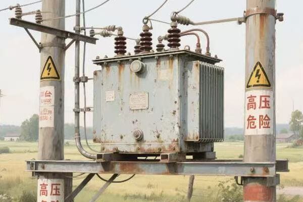
Safety Spotting: Identifying Critical Warnings in Pad Mounted Transformer Schematics?
Have you ever felt a chill down your spine when working on a high-voltage transformer? That’s your instinct telling you to be careful. But instinct alone isn’t enough – you need to know how to read the safety warnings in transformer schematics.
Identifying critical warnings in pad mounted transformer schematics is crucial for technician safety. Key elements include high voltage indicators, grounding points, and hazardous material notifications. Understanding these symbols and notes is essential for preventing accidents and ensuring safe maintenance procedures.
Let’s explore how to identify and interpret safety information in transformer schematics:
High Voltage Alerts: The Red Flags
High voltage warnings are the most critical safety indicators in any transformer schematic.
Key High Voltage Indicators:
- Bold red symbols or text
- Lightning bolt icons
- Specific voltage level notations
Grounding Points: Your Safety Anchors
Proper grounding is essential for safe transformer operation and maintenance.
Grounding Symbols:
- Earth ground symbols (usually an inverted triangle)
- Grounding connection points clearly marked
- Notes on required grounding procedures
Hazardous Materials: Hidden Dangers
Transformers often contain materials that require special handling.
Hazardous Material Warnings:
- Oil level indicators and containment notes
- PCB warnings in older transformers
- Specific handling instructions for coolants
Emergency Procedures: When Things Go Wrong
Schematics often include guidance for emergency situations.
Emergency Information:
- Emergency shutdown procedures
- Fire safety instructions
- Contact information for specialized support
Personal Protective Equipment (PPE): Your Last Line of Defense
PPE requirements are often noted in transformer schematics.
PPE Notations:
- Symbols indicating required safety gear
- Notes on specific PPE for different maintenance tasks
- Reminders for proper PPE use
| Safety Element | Typical Symbol | Importance |
|---|---|---|
| High Voltage | Red lightning bolt | Critical – Life-threatening danger |
| Grounding Points | Inverted triangle | High – Essential for safe work |
| Hazardous Materials | Skull and crossbones | High – Requires special handling |
| Emergency Procedures | "In Case of Emergency" box | Medium – Crucial for quick response |
| PPE Requirements | Hard hat, gloves icons | Medium – Personal safety assurance |
I’ll never forget my first day on a transformer maintenance job. I was eager to prove myself and almost made a rookie mistake that could have been fatal. I was about to open a transformer cabinet when my supervisor stopped me. I had forgotten to check if the transformer was fully de-energized and locked out.
That day, he walked me through the proper lockout/tagout procedure step by step. We disconnected the power, applied locks, and placed clear tags indicating maintenance was in progress. He emphasized that this procedure wasn’t just a formality – it was a life-saving practice.
Another crucial lesson came when working on a large substation transformer. Before we started, my team lead insisted we all put on our full PPE, including arc-flash rated suits. Some of the newer team members grumbled about the discomfort, but he was adamant.
During the maintenance, a small error led to an arc flash. Thanks to our PPE, no one was injured. This incident drove home the importance of always wearing proper protective equipment, no matter how routine the task might seem.
Electrical hazard awareness is something I continuously stress in my training sessions. I once witnessed a near-miss where a technician almost contacted a nearby energized bus bar while working on a de-energized transformer. He had forgotten about the risk of induced voltage in adjacent equipment. This incident led us to implement a policy of identifying and marking all potential hazard points before starting work.
One particularly challenging aspect of safety in transformer schematics is interpreting hazardous material warnings. I remember a project involving an older transformer that potentially contained PCBs. The schematic included a small note about this, which could have been easily overlooked. Recognizing this warning allowed us to take necessary precautions and arrange for proper handling and disposal.
Over the years, I’ve learned that safety in transformer maintenance isn’t just about rules and equipment. It’s about creating a culture where safety is everyone’s responsibility. I encourage all team members to speak up if they see something unsafe, no matter their position.
One practice I’ve found particularly effective is conducting pre-job safety briefings. Before each maintenance task, we gather the team to discuss the specific hazards of the job and review safety procedures. This not only refreshes everyone’s knowledge but also allows for questions and clarifications.
I also emphasize the importance of understanding emergency procedures noted in schematics. In one instance, a transformer began to overheat during maintenance. Because we had reviewed the emergency shutdown procedure beforehand, we were able to quickly and safely de-energize the unit, preventing a potential fire.
For new technicians, I always stress the importance of not just identifying safety symbols, but truly understanding what they mean in practical terms. It’s one thing to see a high voltage warning; it’s another to comprehend the real-world implications and necessary precautions it entails.
Remember, safety information in transformer schematics isn’t just there to meet regulations – it’s there to protect lives. Every symbol, every note, and every warning represents a lesson learned, often through hard experience. By mastering the skill of identifying and interpreting these critical warnings, you’re not just becoming a better technician; you’re becoming a guardian of safety in the field.
As you gain experience, you’ll develop an intuitive understanding of these safety elements, but never let familiarity breed complacency. I still approach each schematic with the same careful attention I did on that eye-opening day early in my career. Safety in transformer maintenance is not just a skill – it’s a mindset and a responsibility we all share.
Troubleshooting 101: Using Transformer Diagrams to Solve Common Issues?
Ever found yourself scratching your head in front of a malfunctioning transformer, unsure where to start? The solution might be right in your hands – the transformer diagram. But are you using it to its full potential?
Transformer diagrams are powerful troubleshooting tools for utility technicians. They provide a systematic approach to problem-solving by mapping out component relationships, electrical paths, and potential fault points. Effective use of these diagrams can significantly reduce diagnostic time and improve repair accuracy.
Let’s explore how to leverage your transformer diagram for efficient troubleshooting:
Systematic Approach: Your Troubleshooting Roadmap
A well-structured approach using the diagram can streamline your problem-solving process.
Steps to Follow:
- Start at the point of observed malfunction
- Trace connections backward to potential causes
- Identify test points for measurements
- Systematically eliminate possibilities
Component Relationships: Understanding the Bigger Picture
Diagrams help visualize how transformer components interact.
Key Relationships:
- Core and winding connections
- Bushing to winding paths
- Tap changer influences on voltage
- Cooling system’s role in overall performance
Electrical Pathways: Following the Flow
Tracing electrical paths is crucial for identifying faults.
Path Analysis:
- High voltage to low voltage transformations
- Grounding connections
- Auxiliary power circuits
- Control and monitoring wiring
Fault Point Identification: Pinpointing Problems
Diagrams can help predict and locate common fault points.
Common Fault Areas:
- Insulation breakdown points
- High-stress mechanical joints
- Typical locations for oil leaks
- Vulnerable areas in the cooling system
Measurement Guidance: Where to Probe
Diagrams provide valuable information on where to take measurements.
Measurement Points:
- Voltage test locations
- Current measurement spots
- Resistance check points
- Temperature monitoring areas
| Troubleshooting Aspect | Diagram Use | Real-World Application |
|---|---|---|
| Systematic Approach | Follow component connections | Step-by-step fault tracing |
| Component Relationships | Understand system interactions | Predict cascade failures |
| Electrical Pathways | Trace current flow | Identify open or short circuits |
| Fault Point Identification | Locate common problem areas | Focus inspection efforts |
| Measurement Guidance | Find correct test points | Accurate data collection |
I recall a particularly challenging troubleshooting case early in my career. We were faced with a pad mounted transformer that was tripping offline intermittently. The initial symptoms were vague, and the cause wasn’t immediately apparent. This is where the transformer diagram proved invaluable.
Our first step was to identify the point of observed malfunction. The diagram showed us the connection between the protective relay that was triggering and its associated components. This gave us a starting point to work backward from.
We began tracing the electrical paths on the diagram, looking for potential points of failure. The diagram clearly showed the relationship between the windings, bushings, and protective devices. This visual representation helped us formulate theories about what could be causing the intermittent trips.
One key advantage of using the diagram was that it helped us understand the component relationships. We could see how a problem in one area might affect another, seemingly unrelated part of the transformer. This broader perspective was crucial in narrowing down our search.
As we worked through the troubleshooting process, the diagram guided our measurement efforts. It clearly indicated where we should connect our testing equipment for voltage, current, and resistance measurements. This precision saved us time and reduced the risk of taking incorrect or dangerous measurements.
The breakthrough came when we focused on the fault point identification aspect of the diagram. It highlighted areas prone to insulation breakdown, and we noticed that one of these points was near where we had been detecting anomalies. A closer inspection revealed minor insulation damage that was causing the intermittent faults.
This experience taught me the value of using the diagram as more than just a reference – it was an active troubleshooting tool. Since then, I’ve developed a habit of ‘walking through’ the diagram mentally before and during physical inspections. This practice has helped me spot potential issues more quickly and accurately.
One technique I’ve found particularly useful is annotating working copies of diagrams during troubleshooting. I note down measurements, observations, and theories directly on the diagram. This creates a visual record of the troubleshooting process, which is invaluable for complex problems or when handing over to another technician.
For new technicians, I always stress the importance of understanding the diagram’s legend and symbols thoroughly. Misinterpreting a symbol can lead you down the wrong troubleshooting path, wasting time and potentially overlooking the real issue.
I’ve also learned the value of comparing the actual transformer configuration with the diagram before starting any troubleshooting. Sometimes, modifications or updates to the transformer aren’t reflected in the diagram, and spotting these discrepancies early can prevent confusion later in the process.
One advanced technique I’ve developed is using the diagram to predict potential cascade failures. By understanding how components interact, you can often anticipate how a fault in one area might affect others, allowing for more comprehensive problem-solving.
Remember, effective troubleshooting isn’t just about finding the immediate problem – it’s about understanding the root cause. The transformer diagram is your map to tracing issues back to their source, ensuring that your repairs address the underlying issue, not just the symptoms.
As you gain experience, you’ll find that your ability to ‘read between the lines’ of a transformer diagram improves. You’ll start to recognize patterns and potential issues more quickly, making your troubleshooting more efficient and effective.
Using your transformer diagram as a problem-solving tool is a skill that develops over time. It combines technical knowledge, practical experience, and a bit of detective work. Master this skill, and you’ll find yourself solving even the most complex transformer issues with confidence and precision.
Conclusion
Interpreting pad mounted transformer diagrams is a crucial skill for utility technicians. From understanding basic layouts to troubleshooting complex issues, these diagrams are invaluable tools. By mastering diagram reading, symbol interpretation, safety awareness, and troubleshooting techniques, technicians can significantly enhance their effectiveness and safety in the field.
