Are you struggling with installing a pad mounted transformer concrete pad? You’re not alone. Many contractors find this process challenging, but it’s crucial for ensuring the safety and efficiency of electrical distribution systems.
This guide provides a comprehensive overview of installing pad mounted transformer concrete pads according to First Energy standards. It covers site preparation, pad design, concrete pouring, curing, transformer placement, electrical connections, and final inspection. Following these steps ensures a safe and compliant installation.
In this article, I’ll walk you through the entire process of installing a pad mounted transformer concrete pad, adhering to First Energy standards. Whether you’re a seasoned contractor or new to the field, this guide will help you ensure a safe and compliant installation. Let’s dive in and explore each step in detail.
What is a Pad Mounted Transformer: Understanding the Basics and First Energy Standards?
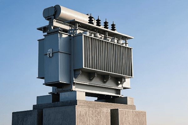
Have you ever wondered about those green boxes you see in residential areas? Those are pad mounted transformers, but what exactly are they, and why do they need special concrete pads?
Pad mounted transformers are ground-level electrical distribution devices that step down voltage for residential or commercial use. First Energy standards require specific concrete pad installations to ensure safety, accessibility, and longevity of these transformers in various environmental conditions.
Let’s delve deeper into pad mounted transformers and the First Energy standards for their installation. Understanding these basics is crucial for anyone involved in electrical distribution projects.
Pad Mounted Transformer Basics
-
Function
- Steps down higher distribution voltages to usable levels
- Typically transforms 7.2kV or 14.4kV to 120/240V for residential use
-
Components
- Transformer core and windings
- Insulating oil or dry-type insulation
- Protective enclosure
-
Advantages
- Aesthetically pleasing compared to pole-mounted transformers
- Easier maintenance access
- Enhanced safety features
First Energy Standards
-
Pad Specifications
- Minimum dimensions and thickness
- Reinforcement requirements
- Concrete strength specifications
-
Location Requirements
- Minimum distances from buildings and other structures
- Accessibility for maintenance vehicles
- Flood plain considerations
-
Safety Features
- Grounding requirements
- Protective bollards in high-traffic areas
- Locking mechanisms on transformer enclosures
| Aspect | First Energy Requirement | Reason |
|---|---|---|
| Pad Thickness | Minimum 6 inches | Ensure stability and load-bearing capacity |
| Concrete Strength | 4000 psi minimum | Durability and longevity |
| Grounding | Copper ground ring | Electrical safety |
| Clearance | 10 feet from buildings | Fire safety and maintenance access |
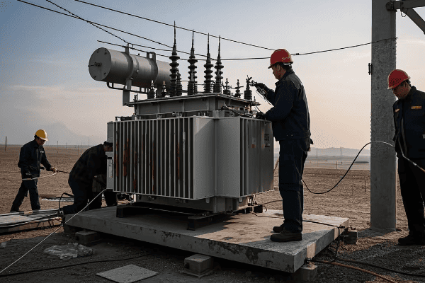
Pad mounted transformers have become increasingly common in modern electrical distribution systems. I remember my first encounter with these devices early in my career. I was working on a new residential development project, and the utility company specified pad mounted transformers instead of the traditional pole-mounted units. The sleek, low-profile design was a stark contrast to the overhead transformers I was used to seeing.
The basic function of a pad mounted transformer is to step down the higher distribution voltages to levels usable in homes and businesses. Typically, they transform voltages from 7.2kV or 14.4kV down to 120/240V for residential use. What’s fascinating about these transformers is how they pack all the necessary components into such a compact, ground-level package.
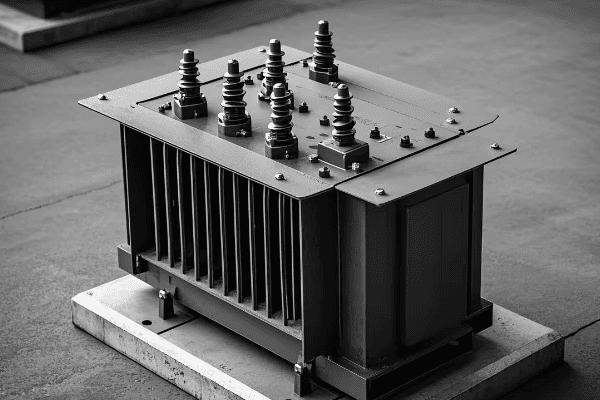
Inside the green enclosure, you’ll find the transformer core and windings, similar to what you’d see in a pole-mounted transformer. However, the design is optimized for ground-level installation. Many pad mounted transformers use oil for insulation and cooling, although dry-type units are also available for environmentally sensitive areas. I once worked on a project near a wetland where we specifically chose dry-type pad mounted transformers to eliminate any risk of oil leaks.
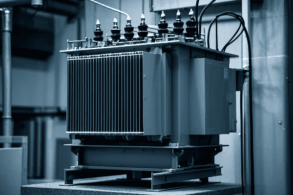
One of the main advantages of pad mounted transformers is their aesthetic appeal. In residential areas, they’re much less obtrusive than pole-mounted transformers. They also offer easier access for maintenance, which I’ve found to be a significant benefit during routine inspections and repairs.
Now, let’s talk about First Energy standards for these installations. First Energy, like many utilities, has specific requirements for pad mounted transformer installations to ensure safety, reliability, and longevity. These standards cover everything from the concrete pad specifications to the transformer’s location and safety features.
The concrete pad is a critical component of the installation. First Energy typically requires a minimum pad thickness of 6 inches. This might seem excessive, but I’ve seen firsthand how this thickness ensures stability, even in areas with poor soil conditions. The concrete strength is also specified, usually at a minimum of 4000 psi. This high strength ensures the pad can withstand the weight of the transformer and resist cracking over time.
Location requirements are another crucial aspect of First Energy standards. They typically specify minimum distances from buildings and other structures. In most cases, I’ve had to maintain at least 10 feet of clearance from buildings. This clearance is crucial for fire safety and to allow access for maintenance vehicles. I remember a challenging project where we had to redesign the entire site layout to accommodate these clearance requirements.
First Energy also has specific standards for safety features. Grounding is a critical requirement, usually involving a copper ground ring around the pad. In high-traffic areas, they often require protective bollards to prevent vehicle impacts. I once worked on a commercial project where we had to install bollards around the transformer pad due to its proximity to a parking area.
One interesting aspect of First Energy standards is their consideration of future needs. They often require oversized pads to accommodate potential transformer upgrades. This forward-thinking approach has saved time and money on several projects I’ve been involved with, where load growth necessitated larger transformers.
Understanding these basics and standards is crucial for anyone involved in pad mounted transformer installations. Whether you’re a contractor, an engineer, or a utility worker, knowing these requirements ensures a safe, compliant, and efficient installation. As we move forward in this guide, we’ll explore how these standards translate into practical installation steps.
Site Preparation: Soil Assessment and Grading for Concrete Pad Installation?
Are you unsure about how to prepare the site for your pad mounted transformer’s concrete pad? Proper site preparation is crucial for the stability and longevity of your installation. But where do you start?
Site preparation for a pad mounted transformer concrete pad involves thorough soil assessment and precise grading. This process ensures a stable foundation, proper drainage, and compliance with First Energy standards. Key steps include soil testing, excavation, compaction, and establishing the correct grade and elevation.
Let’s explore the critical steps in site preparation for your pad mounted transformer concrete pad. Understanding this process is essential for a successful and compliant installation.
Soil Assessment
-
Soil Testing
- Determine soil type and bearing capacity
- Identify potential issues like expansive soils or high water tables
-
Geotechnical Report
- Professional analysis of soil conditions
- Recommendations for foundation design
-
Drainage Evaluation
- Assess natural water flow patterns
- Plan for proper drainage around the pad
Grading Process
-
Excavation
- Remove topsoil and organic matter
- Dig to the required depth for the pad and any sub-base material
-
Compaction
- Use appropriate equipment to compact the soil
- Achieve specified density for stability
-
Leveling
- Establish correct grade and elevation
- Ensure proper slope for drainage
| Step | Key Consideration | First Energy Requirement |
|---|---|---|
| Soil Testing | Bearing capacity | Minimum 2000 psf |
| Excavation Depth | Frost line and pad thickness | Below frost line + pad thickness |
| Compaction | Soil density | 95% of maximum dry density |
| Final Grade | Slope for drainage | 1% slope away from pad |
Site preparation is a critical phase in the installation of a pad mounted transformer concrete pad. I’ve learned through experience that taking the time to properly prepare the site can prevent a host of problems down the line. Let me walk you through the process, sharing some insights I’ve gained over the years.
The first step in site preparation is soil assessment. This is not just a formality – it’s a crucial step that can make or break your installation. I remember a project early in my career where we skipped a thorough soil assessment. We ended up with significant settling issues that required costly repairs. Since then, I always insist on proper soil testing.
Soil testing involves determining the soil type and its bearing capacity. First Energy typically requires a minimum bearing capacity of 2000 psf (pounds per square foot). I’ve worked with geotechnical engineers who use various methods to test this, including plate load tests and penetrometer tests. The results of these tests are crucial for designing the pad and ensuring its long-term stability.
One particularly challenging project I worked on involved expansive clay soils. These soils swell when wet and shrink when dry, which can cause significant movement in structures. We had to design a special sub-base system to mitigate this issue. It involved excavating deeper than usual and installing a layer of non-expansive material. This experience taught me the importance of understanding not just the current soil conditions, but how they might change with moisture fluctuations.
A geotechnical report is often necessary, especially for larger installations or in areas with known soil issues. This report provides a professional analysis of the soil conditions and recommendations for the foundation design. I’ve found these reports invaluable in complex sites, as they often identify potential issues that might not be apparent from a simple visual inspection.
Drainage evaluation is another critical aspect of site preparation. Water is one of the biggest enemies of a stable foundation. I always take time to assess the natural water flow patterns on the site. In one project, we discovered that the proposed pad location was in a natural drainage path. We had to redesign the site grading to divert water away from the pad area. This extra effort in the planning stage prevented potential flooding issues in the future.
Once the assessment is complete, we move on to the grading process. The first step is excavation. We remove all topsoil and organic matter from the pad area. The depth of excavation is determined by two factors: the frost line in the area and the thickness of the pad. First Energy typically requires the bottom of the pad to be below the frost line to prevent frost heave. I always excavate a bit deeper than the minimum requirement to allow for a layer of compacted gravel sub-base. This extra step improves drainage and stability.
Compaction is a critical step that’s often underestimated. Proper compaction prevents settling and ensures the pad remains level over time. First Energy usually requires the soil to be compacted to 95% of its maximum dry density. I use specialized compaction equipment and often bring in a technician to test the compaction levels. It’s not uncommon to need multiple passes with the compactor to achieve the required density.
The final step in grading is leveling the site and establishing the correct elevation. This is where precision is key. I use laser levels to ensure the grade is exactly right. First Energy typically requires a slight slope away from the pad for drainage – usually about 1%. This slope might seem minor, but it’s crucial for preventing water from pooling around the transformer.
Throughout the site preparation process, I always keep First Energy’s standards in mind. They have specific requirements for each step, from the minimum bearing capacity of the soil to the final grade of the site. Meeting these standards is not just about compliance – it’s about ensuring the long-term stability and safety of the installation.
Site preparation might not be the most glamorous part of installing a pad mounted transformer, but it’s undoubtedly one of the most important. Taking the time to properly assess the soil, prepare the site, and establish the correct grade sets the foundation for a successful installation. As we move forward in this guide, you’ll see how this careful preparation pays off in the subsequent steps of the installation process.
Concrete Pad Design: Dimensions, Reinforcement, and Load-Bearing Considerations?
Are you puzzled about how to design the concrete pad for your pad mounted transformer? The design of this pad is crucial – it needs to support the transformer’s weight, withstand environmental factors, and meet First Energy’s stringent standards. But where do you start?
Concrete pad design for pad mounted transformers involves precise dimensioning, proper reinforcement, and careful load-bearing calculations. First Energy standards typically require a minimum 6-inch thickness, 4000 psi concrete strength, and specific rebar arrangements. The pad must accommodate the transformer’s weight, oil containment, and potential future upgrades.
Let’s dive into the details of designing a concrete pad for your pad mounted transformer. Understanding these elements is key to creating a stable, long-lasting foundation that meets all regulatory requirements.
Pad Dimensions
-
Size Determination
- Based on transformer dimensions and First Energy standards
- Typically extends 6-12 inches beyond transformer on all sides
-
Thickness
- Minimum 6 inches as per First Energy requirements
- May be thicker based on soil conditions and transformer weight
-
Elevation
- Usually 4-6 inches above final grade
- Sloped for drainage (typically 1% slope)
Reinforcement Design
-
Rebar Specifications
- Typically #4 or #5 rebar
- Placed in a grid pattern, usually 12 inches on center
-
Placement
- Two layers of rebar (top and bottom of pad)
- Minimum 2 inches of concrete cover over rebar
-
Tie-downs
- Anchor bolts or inserts for securing the transformer
- Placed according to transformer manufacturer specifications
Load-Bearing Considerations
-
Weight Calculation
- Account for transformer weight (including oil)
- Factor in potential future upgrades
-
Soil Pressure
- Ensure pad design distributes weight evenly
- Consider dynamic loads (e.g., during installation)
-
Environmental Factors
- Design for freeze-thaw cycles in cold climates
- Account for potential flooding or seismic activity
| Aspect | Typical Specification | First Energy Requirement |
|---|---|---|
| Pad Size | Transformer footprint + 6-12 inches | Varies by transformer size |
| Thickness | 6 inches minimum | 6 inches minimum |
| Concrete Strength | 4000 psi | 4000 psi minimum |
| Rebar Size | #4 or #5 | As per engineer’s design |
| Rebar Spacing | 12 inches on center | As per engineer’s design |
Designing the concrete pad for a pad mounted transformer is a task that requires careful consideration of multiple factors. Over the years, I’ve learned that a well-designed pad is the foundation of a reliable transformer installation. Let me share some insights I’ve gained through my experience.
The first consideration in pad design is dimensioning. The size of the pad is primarily determined by the dimensions of the transformer it will support. First Energy typically requires the pad to extend 6-12 inches beyond the transformer on all sides. This extra space serves several purposes. It provides a stable base that distributes the weight more evenly, it allows for easier installation and maintenance access, and it accommodates potential oil spills.
I remember a project where we initially designed the pad to the minimum size requirement. During installation, we realized this made it difficult for the crew to maneuver around the transformer. Since then, I always design pads with a bit more extra space than the minimum requirement. It makes installation and future maintenance much easier.
The thickness of the pad is another crucial dimension. First Energy typically requires a minimum thickness of 6 inches. However, I’ve found that in some cases, especially with larger transformers or in areas with poor soil conditions, a thicker pad may be necessary. I once worked on a project in an area with expansive clay soils where we increased the pad thickness to 8 inches to provide extra stability.
Elevation is also an important consideration. The pad is usually designed to sit 4-6 inches above the final grade. This elevation helps prevent water from pooling around the transformer. We always include a slight slope (typically 1%) away from the center of the pad for drainage. I’ve seen installations where this slope was overlooked, and it led to water accumulation issues during heavy rains.
Moving on to reinforcement design, this is where the pad gets its strength. First Energy doesn’t typically specify exact rebar requirements, leaving it to the engineer’s design. However, in my experience, #4 or #5 rebar in a 12-inch on center grid pattern works well for most installations. We always use two layers of rebar – one near the bottom of the pad and one near the top. This dual-layer approach helps resist both positive and negative bending moments.
The placement of the rebar is critical. We ensure a minimum of 2 inches of concrete cover over the rebar to prevent corrosion. I’ve seen pads where the rebar was too close to the surface, and over time, it led to cracking and spalling of the concrete.
Tie-downs are another important element of the pad design. These are typically anchor bolts or inserts that secure the transformer to the pad. The exact specifications for these tie-downs usually come from the transformer manufacturer. I always double-check these specificationsI always double-check these specifications with the manufacturer before finalizing the pad design. In one project, we had to make last-minute adjustments because the tie-down locations didn’t match the transformer’s mounting points. It’s a small detail, but it can cause significant delays if overlooked.
Load-bearing considerations are crucial in pad design. The pad must support not just the weight of the transformer, but also its oil. I always factor in the possibility of future upgrades too. It’s not uncommon for utilities to replace transformers with larger units as power demands increase. Designing the pad to handle a bit more weight than currently needed can save a lot of trouble down the line.
Soil pressure is another key factor. The pad design needs to distribute the transformer’s weight evenly to prevent settling. I work closely with geotechnical engineers to ensure the pad design matches the soil conditions. In areas with poor soil, we sometimes use a larger pad or incorporate a sub-base of compacted gravel to better distribute the load.
Environmental factors can’t be ignored in pad design. In cold climates, the pad must withstand freeze-thaw cycles. I’ve used air-entraining admixtures in the concrete mix to improve its resistance to these cycles. In areas prone to flooding, we might design the pad to be higher above grade or incorporate additional drainage features. Seismic considerations are also important in some regions, potentially requiring additional reinforcement or special tie-down systems.
One aspect of pad design that’s often overlooked is oil containment. Many jurisdictions now require transformer pads to be designed with oil containment features to prevent environmental contamination in case of a leak. I’ve worked on designs that incorporate a slight depression in the center of the pad with a surrounding curb to contain any potential oil spills.
The concrete mix design is also crucial. First Energy typically requires a minimum compressive strength of 4000 psi. I often specify a mix with a lower water-to-cement ratio to improve durability and reduce shrinkage cracking. Adding fiber reinforcement to the mix can also help control cracking and improve the pad’s overall toughness.
Finally, I always consider future maintenance needs in the pad design. This might include incorporating conduit stub-ups for future wiring needs or designing the pad with slightly larger dimensions to allow for easier transformer replacement.
Designing a concrete pad for a pad mounted transformer is a complex task that requires balancing multiple factors. It’s not just about meeting minimum standards – it’s about creating a foundation that will ensure the safe and reliable operation of the transformer for decades to come. As we move on to the next steps in the installation process, you’ll see how this careful design translates into a robust and long-lasting installation.
Forming and Pouring the Concrete Pad: Step-by-Step Process and Best Practices?
Are you feeling overwhelmed by the prospect of forming and pouring the concrete pad for your pad mounted transformer? This critical step can make or break your installation. But don’t worry – with the right approach, you can ensure a smooth and successful pour.
Forming and pouring a concrete pad for a pad mounted transformer involves careful preparation, precise formwork, proper concrete mixing and placement, and attentive finishing. Key steps include setting up sturdy forms, placing reinforcement correctly, ensuring proper concrete consistency, and finishing the surface for durability and drainage.
Let’s walk through the process of forming and pouring your concrete pad, step by step. I’ll share some best practices I’ve learned over the years to help you achieve the best possible result.
Formwork Setup
-
Form Material Selection
- Use sturdy lumber or metal forms
- Ensure forms are straight and properly braced
-
Form Placement
- Set forms to exact dimensions and elevations
- Use stakes and braces to secure forms
-
Form Release Agent
- Apply to inside of forms for easy removal
- Use a product compatible with concrete mix
Reinforcement Placement
-
Rebar Grid
- Place bottom layer of rebar on chairs
- Tie intersections securely
-
Top Layer
- Install after bottom layer is complete
- Ensure proper concrete cover
-
Tie-Down Inserts
- Place accurately according to transformer specifications
- Secure firmly to prevent movement during pour
Concrete Pouring
-
Mix Preparation
- Use specified concrete mix (typically 4000 psi)
- Ensure proper slump for workability
-
Placement Technique
- Pour concrete evenly across the pad
- Use vibration to eliminate air pockets
-
Leveling
- Screed surface to achieve proper elevation and slope
- Check levels frequently during pour
Finishing
-
Initial Finishing
- Float surface to embed large aggregates
- Begin when bleed water has evaporated
-
Final Finishing
- Broom finish for slip resistance
- Ensure proper slope for drainage
-
Curing Preparation
- Apply curing compound or prepare for water curing
- Protect surface from rapid drying
| Step | Key Consideration | Best Practice |
|---|---|---|
| Formwork | Stability and Accuracy | Use sturdy forms, check dimensions multiple times |
| Reinforcement | Proper Placement | Use chairs and ties, check cover before pour |
| Pouring | Consistency and Consolidation | Use vibration, maintain even pour rate |
| Finishing | Surface Quality and Drainage | Time finishing correctly, maintain slope |
Forming and pouring the concrete pad for a pad mounted transformer is a critical process that requires attention to detail and careful execution. Over the years, I’ve poured many of these pads, and I’ve learned that preparation and precision are key to success.
Let’s start with the formwork setup. The choice of form material is important. I prefer to use sturdy lumber forms for most projects. They’re cost-effective and easy to work with. For larger pads or in situations where the forms will be reused multiple times, metal forms can be a good investment. Whatever material you choose, the key is to ensure the forms are straight and properly braced. I’ve seen pads end up out of square or with bulging sides due to inadequate formwork, and it’s not a pretty sight.
When placing the forms, precision is crucial. I always double-check the dimensions and elevations before securing the forms. A small error at this stage can lead to big problems later. I use a combination of stakes and braces to secure the forms. It’s important to anticipate the pressure of the wet concrete – forms that seem sturdy when empty can shift or bulge when filled with concrete.
Don’t forget to apply a form release agent to the inside of the forms. This makes removal much easier and results in a cleaner finish on the concrete. I prefer to use a biodegradable release agent, especially when working in environmentally sensitive areas.
Moving on to reinforcement placement, this is where the strength of your pad is built. I always start with the bottom layer of rebar, using chairs to ensure it’s at the correct height. Tying the intersections securely is important – I’ve seen poorly tied rebar shift during the pour, compromising the pad’s strength.
The top layer of rebar goes in after the bottom layer is complete. Again, ensuring proper concrete cover is crucial. I use spacers to maintain the correct distance between the top rebar and the surface of the pad. This cover protects the rebar from corrosion and ensures the pad’s long-term durability.
Placing the tie-down inserts accurately is critical. These need to align perfectly with the transformer’s mounting points. I always double-check the transformer specifications and measure multiple times before securing these inserts. They need to be firmly attached to the rebar grid to prevent movement during the pour.
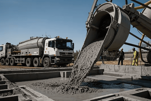
When it comes to the actual concrete pouring, preparation is key. I always use the specified concrete mix – typically 4000 psi for transformer pads. The slump of the concrete is important for workability. Too wet, and you risk reducing the strength of the concrete; too dry, and it becomes difficult to work with and consolidate properly.
During the pour, I focus on even placement across the pad. Pouring too much in one area can lead to uneven settling. Using a concrete vibrator is crucial to eliminate air pockets and ensure good consolidation around the rebar. I make sure to vibrate thoroughly but avoid over-vibration, which can cause segregation of the concrete mix.
Leveling the concrete as you pour is important. I use a screed board to achieve the proper elevation and slope. Frequent checks with a level during this process help ensure the final pad meets the required specifications.
Finishing the pad is where skill and timing come into play. I start the initial floating when the bleed water has evaporated from the surface. This embeds the large aggregates and prepares the surface for final finishing. The timing of this step is crucial – too early, and you’ll trap bleed water in the surface; too late, and the concrete becomes difficult to work.
For the final finish, I typically use a broom finish to provide slip resistance. The direction of the broom strokes is important – I always broom perpendicular to the slope to aid in water runoff. Maintaining the proper slope during finishing is critical for drainage.
Finally, proper curing is essential for the pad’s strength and durability. I either apply a curing compound or prepare for water curing immediately after finishing. Protecting the surface from rapid drying, especially in hot or windy conditions, is crucial to prevent cracking.
Throughout the entire process, I’m constantly checking and rechecking measurements, levels, and specifications. It’s much easier to make adjustments before the concrete sets than to try to fix issues later. With careful attention to detail and adherence to best practices, you can pour a concrete pad that will provide a stable and durable foundation for your pad mounted transformer for years to come.
Curing and Finishing: Ensuring Durability and Proper Surface Preparation?
Are you concerned about the long-term durability of your transformer pad? The curing and finishing process is critical for ensuring the pad’s strength and longevity. But how do you get it right?
Proper curing and finishing of a transformer concrete pad involves maintaining optimal moisture conditions, protecting the surface from damage, and applying appropriate finishing techniques. This process ensures the concrete reaches its full strength potential and develops a durable, well-prepared surface for the transformer installation.
Let’s explore the crucial steps of curing and finishing your transformer concrete pad. I’ll share some techniques I’ve found effective over the years to achieve the best possible results.
Curing Process
-
Moisture Retention
- Apply curing compound or use wet burlap
- Maintain moisture for at least 7 days
-
Temperature Control
- Protect from extreme temperatures
- Use insulating blankets in cold weather
-
Protection
- Fence off area to prevent foot traffic
- Cover pad to protect from rain or debris
Finishing Techniques
-
Surface Texturing
- Apply broom finish for slip resistance
- Ensure consistent texture across pad
-
Edging
- Use edging tool for smooth, rounded edges
- Helps prevent chipping and spalling
-
Joint Cutting
- Cut control joints if required by design
- Typically 1/4 depth of pad thickness
Surface Preparation
-
Cleaning
- Remove any debris or laitance
- Pressure wash if necessary
-
Leveling
- Check for high or low spots
- Grind down high spots if needed
-
Sealing
- Apply concrete sealer if specified
- Helps protect against oil stains and moisture
| Aspect | Key Consideration | Best Practice |
|---|---|---|
| Curing Duration | Minimum 7 days | Longer curing for higher strength |
| Moisture Retention | Prevent premature drying | Use curing compound or wet burlap |
| Surface Texture | Slip resistance | Consistent broom finish |
| Edge Treatment | Durability | Round edges with proper tool |
The curing and finishing process is where the concrete pad for your pad mounted transformer really develops its strength and durability. Over the years, I’ve learned that this stage is just as critical as the pour itself. Let me walk you through the process and share some insights I’ve gained.
Let’s start with curing. The goal here is to maintain optimal moisture conditions in the concrete as it hardens. This is crucial for the concrete to reach its full strength potential. I typically use one of two methods: applying a curing compound or using wet burlap. Curing compounds are convenient and effective, forming a membrane that prevents moisture loss. I prefer to use a clear compound that allows me to monitor the concrete’s color as it cures.
When using wet burlap, I make sure to keep it consistently moist for at least 7 days. This method requires more attention but can be very effective, especially in hot or windy conditions. I remember a project in a particularly dry climate where we used wet burlap and set up a simple sprinkler system to keep it moist. The extra effort paid off in the quality of the final pad.
Temperature control during curing is also important. Extreme heat or cold can affect the curing process and the final strength of the concrete. In hot weather, I sometimes use evaporative cooling techniques to prevent the concrete from drying too quickly. In cold weather, insulating blankets are essential. I once worked on a project where we had to pour a pad in near-freezing temperatures. We used insulating blankets and even set up temporary heaters to ensure proper curing.
Protection during the curing process is crucial. I always fence off the area to prevent foot traffic. It’s also important to cover the pad to protect it from rain or debris. I’ve seen pads damaged by unexpected rainstorms or by workers accidentally walking on them too soon. A little caution goes a long way in ensuring a perfect finish.
Moving on to finishing techniques, the surface texture is an important consideration. For transformer pads, I typically apply a broom finish. This provides good slip resistance, which is important for safety during transformer installation and maintenance. The key is to achieve a consistent texture across the entire pad. I usually make passes with the broom perpendicular to the slope to aid in water runoff.
Edging is another important finishing step. I use an edging tool to create smooth, rounded edges around the perimeter of the pad. This not only looks better but also helps prevent chipping and spalling of the edges over time. It’s a small detail that makes a big difference in the pad’s long-term durability.
In some cases, particularly for larger pads, control joints may be required. These are typically cut to about 1/4 the depth of the pad thickness. The purpose is to control where cracking occurs if the concrete shrinks. I’ve found that properly placed control joints can significantly extend the life of a concrete pad.
After the concrete has cured, surface preparation is the final step. I always start by thoroughly cleaning the surface, removing any debris or laitance (a weak layer of cement and fine particles on the surface). If necessary, I’ll use a pressure washer to ensure a clean surface.
Next, I check for any high or low spots on the pad. This is crucial for ensuring proper transformer placement and drainage. High spots can be ground down if needed. Low spots are more problematic and might require a leveling compound if they’re significant.
Finally, depending on the specifications, I might apply a concrete sealer. This helps protect the pad against oil stains and moisture penetration. It’s particularly useful in areas where oil leaks from the transformer are a concern.
Throughout the curing and finishing process, I’m constantly monitoring the pad for any signs of problems like cracking or uneven curing. Catching and addressing issues early is much easier than trying to fix them later.
The curing and finishing stage is where your concrete pad transforms from a wet mix into a durable, long-lasting foundation for your pad mounted transformer. By paying attention to moisture retention, temperature control, proper finishing techniques, and surface preparation, you can ensure that your pad will provide a stable and reliable base for years to come. As we move on to the next steps in the installation process, you’ll see how this careful preparation sets the stage for a successful transformer placement.
Transformer Placement: Techniques for Safe and Accurate Positioning on the Pad?
Are you worried about how to safely and accurately place your pad mounted transformer? This critical step requires precision and care to ensure proper installation and long-term performance. But how do you get it right?
Transformer placement involves careful planning, proper equipment selection, and precise positioning techniques. Key steps include preparing the pad surface, using appropriate lifting equipment, aligning the transformer correctly, and securing it to the pad. Safety and accuracy are paramount throughout the process.
Let’s dive into the techniques for safely and accurately placing your pad mounted transformer. I’ll share some strategies I’ve developed over years of experience to ensure a smooth and successful installation.
Preparation
-
Pad Inspection
- Check for levelness and cleanliness
- Verify anchor bolt positions
-
Equipment Selection
- Choose appropriate crane or lift
- Ensure equipment is rated for transformer weight
-
Safety Setup
- Establish clear work zone
- Brief all personnel on safety procedures
Lifting and Positioning
-
Attachment
- Use proper lifting lugs or brackets
- Verify secure attachment before lifting
-
Lifting Operation
- Lift slowly and steadily
- Use guide ropes for control
-
Alignment
- Align transformer with anchor bolts
- Check clearances on all sides
Securing and Finalizing
-
Lowering
- Lower transformer slowly onto pad
- Guide into final position
-
Anchoring
- Secure transformer to anchor bolts
- Torque nuts to specified values
-
Final Checks
- Verify level and alignment
- Check for any damage during placement
| Step | Key Consideration | Best Practice |
|---|---|---|
| Lifting | Weight capacity | Use crane rated for 1.5x transformer weight |
| Alignment | Precision | Use laser levels for accurate positioning |
| Anchoring | Proper torque | Use calibrated torque wrench |
| Final Check | Comprehensive inspection | Use checklist for consistency |
Transformer placement is a critical operation that requires a combination of precision, safety awareness, and technical skill. Over the years, I’ve placed numerous pad mounted transformers, and I’ve learned that careful preparation and attention to detail are key to a successful installation.
Let’s start with preparation. Before the transformer arrives, I always conduct a thorough inspection of the pad. I check for levelness using a precision level – even small deviations can cause issues with transformer operation. I also verify that the pad is clean and free of debris. Any foreign objects on the pad can interfere with proper seating of the transformer.
Verifying the anchor bolt positions is crucial. I once had a situation where the anchor bolts didn’t align with the transformer’s mounting holes. We caught it during the pre-placement inspection, which saved us from a very difficult situation during the actual placement. Since then, I always double-check these measurements against the transformer specifications before the unit arrives on site.
Selecting the right equipment is vital for safe placement. I typically use a crane for larger transformers, ensuring it’s rated for at least 1.5 times the transformer’s weight. For smaller units, a forklift with the appropriate capacity can work well. I always verify the equipment’s certification and inspect it before use.
Safety setup is non-negotiable. I establish a clear work zone around the pad, keeping unnecessary personnel away from the lifting area. Before we begin, I hold a safety briefing with all involved personnel, covering the lifting plan, potential hazards, and emergency procedures. This might seem like overkill for a routine operation, but I’ve found that these briefings help keep everyone alert and focused.
When it comes to the actual lifting operation, proper attachment is critical. I use the lifting lugs or brackets specified by the manufacturer, checking them carefully for any signs of damage or wear. Before the main lift, I always do a test lift of a few inches to verify that the transformer is balanced and the attachments are secure.
During the lift, slow and steady is the way to go. Sudden movements can cause the transformer to swing, potentially damaging it or injuring personnel. I use guide ropes to control the transformer’s movement as it’s lifted. These ropes allow ground personnel to guide the transformer without being directly under the load.
Alignment is where precision really comes into play. I use laser levels to ensure the transformer is perfectly aligned with the anchor bolts. It’s also important to check clearances on all sides – there should be adequate space for ventilation and maintenance access. I remember a project where we had to adjust the transformer’s position by fractions of an inch to meet the utility’s clearance requirements. That level of precision is often necessary.
Lowering the transformer onto the pad is a critical moment. I always lower it slowly, using the crane’s finest control settings. Ground personnel guide the transformer into its final position, often using pry bars for fine adjustments. It’s a tense moment, but with proper preparation and communication, it usually goes smoothly.
Once the transformer is in position, it’s time for anchoring. I use a calibrated torque wrench to tighten the anchor bolts to the manufacturer’s specified torque values. Over-tightening can damage the transformer’s base, while under-tightening can lead to instability. Getting this right is crucial for the long-term stability and safety of the installation.
After anchoring, I conduct a series of final checks. I verify that the transformer is level, using precision levels on multiple points of the unit. I check the alignment again, ensuring it’s square with the pad and properly positioned for cable entries. I also do a thorough inspection for any signs of damage that might have occurred during placement – even small dents or scratches can be indicators of more serious issues.
One aspect of transformer placement that’s often overlooked is the impact on the surrounding area. I always check that the placement hasn’t disturbed the grading around the pad. Proper drainage away from the transformer is crucial for its long-term reliability.
Throughout the placement process, I maintain constant communication with the crane operator and ground personnel. Clear, concise communication helps prevent misunderstandings that could lead to accidents or improper placement.
I’ve found that using a detailed checklist for the placement process helps ensure consistency and that no steps are missed. This is especially useful when working with a team or on multiple installations.
Transformer placement might seem straightforward, but it’s a process where experience really counts. Each installation has its unique challenges, whether it’s tight clearances, difficult site access, or specific utility requirements. By following these techniques and best practices, you can ensure that your pad mounted transformer is placed safely and accurately, setting the stage for reliable operation for years to come.
Grounding and Electrical Connections: Meeting First Energy Requirements?
Are you unsure about how to properly ground your pad mounted transformer and make the electrical connections? This critical step ensures the safety and proper functioning of your installation. But how do you meet First Energy’s specific requirements?
Grounding and electrical connections for pad mounted transformers must meet First Energy’s strict standards. This involves installing a proper grounding system, making secure primary and secondary connections, and ensuring all components are rated for the specific voltage and current levels. Proper techniques and materials are crucial for safety and compliance.
Let’s explore the process of grounding your pad mounted transformer and making the electrical connections according to First Energy requirements. I’ll share some insights from my experience to help you navigate this crucial phase of the installation.
Grounding System Installation
-
Ground Rod Installation
- Drive copper-clad steel rods to required depth
- Typically 5/8 inch diameter, 8 feet long
-
Ground Ring
- Install bare copper wire around transformer pad
- Connect to ground rods and transformer tank
-
Connections
- Use exothermic welds or approved clamps
- Ensure all connections are secure and corrosion-resistant
Primary Connections
-
Cable Preparation
- Strip cables to specified length
- Install stress cones or termination kits
-
Connection to Bushings
- Use appropriate lugs or connectors
- Torque to manufacturer’s specifications
-
Insulation
- Apply insulating materials as required
- Ensure proper coverage and spacing
Secondary Connections
-
Cable Sizing
- Use cables rated for transformer capacity
- Follow First Energy specifications for sizing
-
Connection Methods
- Use approved lugs or compression connectors
- Ensure proper crimping or bolting
-
Arrangement
- Maintain proper phase arrangement
- Allow for future maintenance access
| Aspect | First Energy Requirement | Best Practice |
|---|---|---|
| Ground Rod | 5/8" x 8′ copper-clad steel | Drive to full depth, use multiple if needed |
| Ground Ring | #2 AWG bare copper minimum | Bury 18" deep, 24" from foundation |
| Primary Connections | Rated for system voltage | Use manufacturer-approved connectors |
| Secondary Connections | Sized for full load current | Allow for future load growth |
Grounding and electrical connections are critical aspects of pad mounted transformer installation. They’re not just about meeting code requirements – they’re essential for safety and proper operation. Over the years, I’ve learned that attention to detail in this phase can prevent many problems down the line.
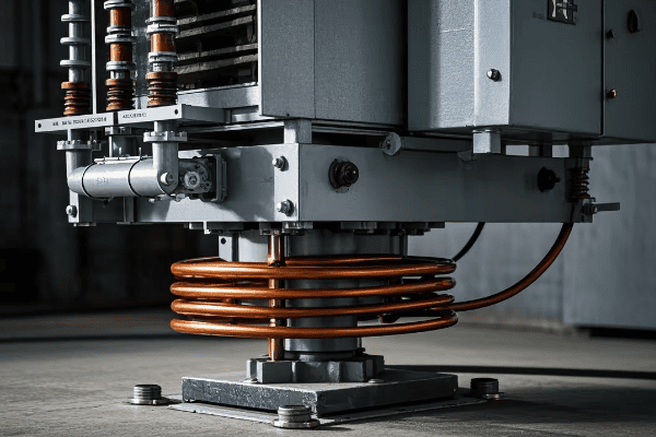
Let’s start with the grounding system. First Energy typically requires a robust grounding setup. I usually begin by installing ground rods. These are typically 5/8 inch diameter, 8-foot long copper-clad steel rods. I drive them into the ground near the transformer pad, ensuring they’re at the full 8-foot depth. In some soil conditions, it might be necessary to use multiple rods to achieve the required ground resistance.
The ground ring is a key component of the grounding system. I install a bare copper wire (usually #2 AWG or larger) around the perimeter of the transformer pad. This wire is typically buried about 18 inches deep and 24 inches out from the foundation. I connect this ring to the ground rods and to the transformer tank. It’s important to use the proper connection methods – I prefer exothermic welds for their reliability and corrosion resistance, but First Energy may also approve certain types of clamps.
I remember a project where we had particularly high soil resistivity. We had to install additional ground rods and use a larger gauge wire for the ground ring to meet First Energy’s resistance requirements. It’s always worth testing the ground resistance before proceeding with the rest of the installation.
Moving on to the primary connections, cable preparation is crucial. I always strip the cables to the exact length specified by First Energy. Over-stripping can lead to flashover issues, while under-stripping can result in poor connections. For medium voltage cables, installing proper stress cones or termination kits is essential. These kits control the electric field at the end of the cable, preventing premature failure.
When connecting to the transformer bushings, I use lugs or connectors that are specifically approved for the application. It’s important to torque these connections to the manufacturer’s specifications. I use a calibrated torque wrench and always document the torque values for future reference.
Insulation of the primary connections is critical. I apply insulating materials as required by First Energy standards, ensuring proper coverage and maintaining the correct spacing between phases and to ground. I’ve seen installations where inadequate insulation led to flashovers during high humidity conditions – it’s not a mistake you want to make.
For secondary connections, cable sizing is important. I always use cables rated for the full capacity of the transformer, following First Energy’s specifications. It’s often worth considering future load growth and sizing the cables accordingly.
When making secondary connections, I use approved lugs or compression connectors. If using compression connectors, it’s crucial to use the correct die and crimping tool. I once saw a connection fail because the wrong crimping tool was used – it looked fine initially but failed under load.
Proper arrangement of the secondary connections is important for both safety and future maintenance. I maintain the correct phase arrangement and ensure there’s enough space for technicians to work safely in the future. It’s also important to label all connections clearly.
Throughout the connection process, I’m always mindful of maintaining proper clearances. This includes phase-to-phase, phase-to-ground, and working clearances. First Energy has specific requirements for these clearances, and adhering to them is crucial for safety and reliability.
One aspect that’s often overlooked is the need for proper support of cables. I use appropriate cable supports and clamps to prevent undue stress on the connections. This is particularly important for the heavier secondary cables.
After completing all connections, I always perform a thorough visual inspection. I check for any signs of damage to insulation, ensure all connections are tight, and verify that all required labels are in place. I also do a final check of the grounding system, making sure all connections are secure.
It’s worth noting that First Energy may have specific requirements for certain types of connections or materials. I always review the latest standards before starting a project, as these can change over time.
Proper documentation is crucial. I record all details of the grounding system and connections, including materials used, torque values, and any test results. This documentation can be invaluable for future maintenance or troubleshooting.
By following these practices and adhering to First Energy’s requirements, you can ensure that your pad mounted transformer is properly grounded and connected. This not only meets regulatory requirements but also sets the foundation for safe and reliable operation of the transformer for years to come.
Final Inspection and Testing: Ensuring Compliance with First Energy Standards?
Are you worried about whether your pad mounted transformer installation meets all of First Energy’s standards? The final inspection and testing phase is crucial for ensuring compliance and safety. But what exactly does this process involve?
Final inspection and testing of pad mounted transformers involve comprehensive checks of all installation aspects, including grounding, connections, insulation, and transformer function. First Energy standards typically require specific tests like insulation resistance, turns ratio, and oil quality checks. Proper documentation and adherence to safety protocols are essential.
Let’s walk through the final inspection and testing process for your pad mounted transformer installation. I’ll share some key steps and insights from my experience to help you ensure full compliance with First Energy standards.
Visual Inspection
-
Pad and Placement
- Check pad condition and transformer alignment
- Verify clearances meet First Energy requirements
-
Connections and Grounding
- Inspect all electrical connections for tightness
- Verify grounding system installation
-
Labeling and Signage
- Ensure all required labels and warning signs are in place
- Check for correct transformer ratings on nameplate
Electrical Testing
-
Insulation Resistance Test
- Measure insulation resistance of windings
- Compare results to First Energy standards
-
Turns Ratio Test
- Verify transformer turns ratio
- Ensure it matches nameplate ratings
-
Winding Resistance Test
- Measure resistance of each winding
- Check for any abnormalities
Functional Checks
-
Voltage Output Test
- Verify correct voltage output on secondary side
- Check for proper phase rotation
-
No-Load Loss Test
- Measure transformer’s no-load losses
- Compare to manufacturer’s specifications
-
Load Tap Changer Operation (if applicable)
- Test operation of load tap changer
- Verify all tap positions function correctly
| Test | First Energy Requirement | Typical Acceptance Criteria |
|---|---|---|
| Insulation Resistance | Minimum 1000 MΩ | >1000 MΩ at 20°C |
| Turns Ratio | Within 0.5% of nameplate | ±0.5% of specified ratio |
| Winding Resistance | Within 2% of factory test | ±2% of factory values |
| No-Load Loss | Within 10% of nameplate | ≤110% of specified losses |
The final inspection and testing phase is where we ensure that all our hard work in installing the pad mounted transformer meets First Energy’s standards. It’s a critical step that I never rush through. Over the years, I’ve developed a systematic approach to this process that has served me well.
Let’s start with the visual inspection. I always begin by checking the pad condition and transformer alignment. I look for any signs of cracking or settling in the pad, and verify that the transformer is level and properly aligned. First Energy has specific requirements for clearances around the transformer, so I measure these carefully. I once had a situation where a transformer was installed too close to a building, and we had to move it – a costly mistake that could have been avoided with proper inspection.
Next, I inspect all electrical connections. I check each connection for tightness, looking for any signs of overheating or corrosion. The grounding system gets special attention – I verify that all ground connections are secure and that the ground ring is installed correctly. I’ve seen cases where ground connections have loosened over time, compromising the safety of the installation.
Labeling and signage are more important than many people realize. I ensure that all required labels and warning signs are in place and legible. This includes checking the transformer nameplate for correct ratings. It’s surprising how often I’ve caught discrepancies between the installed transformer and what was specified – catching these early can prevent serious issues down the line.
Moving on to electrical testing, the insulation resistance test is one of the most critical. I use a megger to measure the insulation resistance of the windings. First Energy typically requires a minimum of 1000 megohms. I always test between each winding and ground, and between windings. If the readings are low, it could indicate moisture in the insulation or other issues that need to be addressed before energizing the transformer.
The turns ratio test is next. This verifies that the transformer’s actual ratio matches its nameplate rating. First Energy usually allows a tolerance of ±0.5%. I use a turns ratio tester and check all tap positions if the transformer has a tap changer. Any significant deviation could indicate a problem with the windings.
Winding resistance tests are also important. I measure the resistance of each winding and compare it to the factory test values. First Energy typically allows a tolerance of ±2%. Significant deviations could indicate issues like shorted turns or poor connections.
Functional checks are the final step in my testing process. I start with a voltage output test once the transformer is energized. This verifies that the secondary voltage is correct and that the phase rotation is proper. I’ve seen cases where incorrect phase rotation has caused serious issues with three-phase loads.
The no-load loss test is another important check. I measure the transformer’s no-load losses and compare them to the manufacturer’s specifications. First Energy usually allows these to be within 10% of the nameplate value. Higher losses could indicate core problems or other issues that affect efficiency.
If the transformer has a load tap changer, I always test its operation. I cycle through all tap positions, verifying that each one functions correctly and that the mechanism operates smoothly. Proper tap changer operation is crucial for voltage regulation.
Throughout the testing process, safety is paramount. I always follow First Energy’s safety protocols, including using appropriate personal protective equipment and following lockout/tagout procedures. I’ve seen too many close calls over the years to ever take safety lightly.
Documentation is a critical part of the final inspection and testing process. I record all test results meticulously, including the date, time, and environmental conditions of each test. This documentation isn’t just for compliance – it’s invaluable for future maintenance and troubleshooting. I remember a case where referring back to the initial test results helped us diagnose a developing issue years after installation.
One aspect of testing that’s often overlooked is the verification of auxiliary systems. If the transformer has cooling fans, temperature monitoring, or pressure relief devices, I make sure to test each of these. First Energy often has specific requirements for these systems, and ensuring they’re functioning correctly is crucial for the transformer’s long-term reliability.
Oil testing is another critical component for oil-filled transformers. I take oil samples and send them for analysis. First Energy typically requires tests for dielectric strength, moisture content, and dissolved gas analysis (DGA). The results of these tests can provide valuable insights into the condition of the transformer and can catch potential issues before they become serious problems.
I also pay close attention to the transformer’s bushings during the final inspection. I check for any signs of damage or contamination and verify that the oil levels in oil-filled bushings are correct. Bushing failures can be catastrophic, so this inspection is crucial.
Another important check is the verification of surge protection devices. If the transformer is equipped with surge arresters, I ensure they’re properly connected and grounded. I’ve seen cases where improperly installed surge arresters have failed to protect the transformer during lightning strikes.
Thermal imaging has become an increasingly valuable tool in my inspection process. After the transformer has been energized and running for a while, I use a thermal camera to check for any hot spots. This can reveal issues like loose connections or overloaded components that might not be apparent through other tests.
One of the final steps in my inspection process is to verify the transformer’s noise level. First Energy often has specific requirements for maximum allowable noise levels, especially in residential areas. I use a sound level meter to ensure the transformer is operating within these limits.
It’s also important to check the transformer’s oil containment system. I verify that the containment area is properly sized and that there are no cracks or damage that could lead to leaks. Environmental protection is a key concern for First Energy, and proper oil containment is crucial.
After all tests are complete, I always conduct a final walk-around inspection. I’m looking for any signs of oil leaks, unusual noises, or vibrations. Sometimes, issues that weren’t apparent during individual tests become noticeable when the transformer is fully operational.
One practice I’ve found valuable is to involve First Energy representatives in the final inspection when possible. Their familiarity with the specific requirements and common issues can be invaluable. It also helps ensure that everyone is on the same page regarding the installation’s compliance.
If any issues are found during the inspection and testing process, it’s crucial to address them immediately. I always document any problems discovered, the corrective actions taken, and the results of follow-up tests. This creates a clear record of how issues were resolved.
Finally, I prepare a comprehensive report of all inspection and test results. This report includes all measurements, observations, and any issues encountered and resolved. I ensure that this report meets all of First Energy’s documentation requirements. It’s not just paperwork – this report serves as a baseline for future maintenance and can be crucial for warranty claims if issues arise later.
Throughout the entire inspection and testing process, I maintain open communication with the project team and First Energy representatives. Clear communication helps ensure that any issues are addressed promptly and that everyone understands the status of the installation.
Remember, the goal of this final inspection and testing is not just to tick boxes on a checklist. It’s about ensuring that the pad mounted transformer is safe, reliable, and fully compliant with First Energy standards. By being thorough and meticulous in this phase, we set the stage for years of trouble-free operation.
This comprehensive approach to final inspection and testing has served me well over the years. It’s caught potential issues before they became problems, ensured compliance with First Energy standards, and provided peace of mind to clients. While it may seem time-consuming, the benefits of a thorough inspection far outweigh the costs of potential failures or non-compliance down the line.
Conclusion
Installing a pad mounted transformer concrete pad according to First Energy standards is a complex process that requires attention to detail at every step. From site preparation and pad design to transformer placement and final testing, each phase is crucial for ensuring a safe, compliant, and reliable installation. By following these guidelines and best practices, you can achieve a high-quality installation that will serve its purpose effectively for years to come.
**
