Are you struggling to understand pad mounted transformer diagrams? You’re not alone. Many electrical engineers find these diagrams complex and confusing.
This comprehensive guide breaks down pad mounted transformer diagrams for electrical engineers. It covers component identification, single-phase vs three-phase comparisons, safety features, connection configurations, symbology, cooling systems, nameplate information, protective devices, industry standards, and practical applications.
As an experienced electrical engineer, I’ve worked with countless pad mounted transformer diagrams. I understand the challenges they present. In this guide, I’ll share my knowledge to help you master these crucial blueprints.
Anatomy of a Pad Mounted Transformer: Decoding the Diagram Components?
Have you ever looked at a pad mounted transformer diagram and felt overwhelmed? Let’s break it down piece by piece.
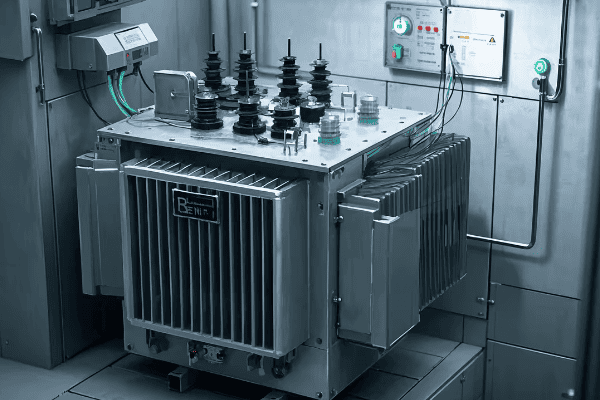
Pad mounted transformer diagrams consist of several key components: the transformer core, primary and secondary windings, bushings, switches, and protective devices. Understanding each element is crucial for interpreting and working with these diagrams effectively.
Let’s dive deeper into the anatomy of a pad mounted transformer diagram:
Transformer Core
The core is the heart of the transformer, represented at the center of the diagram.
Key Features:
- Usually shown as a rectangular or circular shape
- Often includes lamination details
- May indicate core material (e.g., silicon steel)
I remember a project where misinterpreting the core representation led to a major design flaw. Always pay close attention to core details in the diagram.
Primary and Secondary Windings
Windings are crucial components in transformer operation.
Winding Representation:
- Primary windings typically on the left or top
- Secondary windings on the right or bottom
- Number of turns often indicated
Bushings
Bushings are the connection points for external cables.
Bushing Diagram Elements:
- High voltage bushings (usually fewer in number)
- Low voltage bushings (typically more numerous)
- Often represented as circles or rectangles on the diagram edges
Switches and Taps
These components allow for voltage adjustment and isolation.
Common Switch Types:
- On-load tap changers
- Off-circuit tap changers
- Isolation switches
Protective Devices
Safety components are crucial in transformer design.
Protection Elements:
- Surge arresters
- Fuses
- Circuit breakers
| Component | Typical Symbol | Function |
|---|---|---|
| Core | Rectangle or Circle | Magnetic flux path |
| Windings | Curved or Straight Lines | Voltage transformation |
| Bushings | Circles on Diagram Edge | External connections |
| Switches | Small Squares or Circles | Voltage adjustment/isolation |
| Protective Devices | Various (e.g., zigzag for arresters) | Safety and protection |
In my experience, one of the most common mistakes in reading these diagrams is misinterpreting the relationship between primary and secondary windings. I once saw a junior engineer confuse the winding ratios, leading to a completely incorrect voltage calculation.
It’s also crucial to understand that diagram styles can vary between manufacturers. I’ve worked with transformers from different companies, and while the basic principles remain the same, the way components are represented can differ significantly.
Another important aspect is the level of detail in the diagram. Some diagrams are highly detailed, showing every internal connection, while others are more schematic. I always advise engineers to check the diagram’s legend or accompanying documentation to understand the level of detail represented.
Remember, a pad mounted transformer diagram is more than just a picture – it’s a comprehensive representation of the transformer’s internal workings. By understanding each component and its representation, you’ll be better equipped to design, install, and maintain these crucial pieces of electrical infrastructure.
Single-Phase vs Three-Phase: Comparative Analysis of Pad Mounted Transformer Diagrams?
Are you confused about the differences between single-phase and three-phase pad mounted transformer diagrams? You’re not alone. This is a common source of confusion for many engineers.
Single-phase and three-phase pad mounted transformer diagrams differ significantly in their winding arrangements, bushing configurations, and overall complexity. Understanding these differences is crucial for proper transformer selection, installation, and maintenance.
Let’s break down the key differences between single-phase and three-phase pad mounted transformer diagrams:
Winding Arrangements
The winding configuration is a fundamental difference between these two types.
Single-Phase:
- Typically two windings (primary and secondary)
- Simpler arrangement, often shown as two coils
Three-Phase:
- Three sets of windings
- More complex arrangement, usually shown as three interconnected coils
I once worked on a project where a three-phase transformer was mistakenly ordered for a single-phase application. The diagram review would have caught this error early if done correctly.
Bushing Configurations
The number and arrangement of bushings differ significantly.
Single-Phase Bushings:
- Usually two high-voltage bushings
- Two or three low-voltage bushings
Three-Phase Bushings:
- Three high-voltage bushings
- Three or four low-voltage bushings (fourth for neutral)
Vector Group Representation
This is more relevant for three-phase transformers.
Single-Phase:
- No vector group (not applicable)
Three-Phase:
- Vector group indicated (e.g., Dyn11, YNd3)
- Shows phase relationships between primary and secondary
Protective Devices
Safety components may vary between single and three-phase units.
Single-Phase Protection:
- Simpler protection schemes
- Often single-phase fuses or breakers
Three-Phase Protection:
- More complex protection
- Three-phase circuit breakers or fuse sets
| Aspect | Single-Phase | Three-Phase |
|---|---|---|
| Winding Diagram | Two coils | Three interconnected coils |
| Bushing Count | 4-5 total | 6-7 total |
| Vector Group | Not applicable | Indicated (e.g., Dyn11) |
| Complexity | Simpler | More complex |
| Typical Applications | Residential, small commercial | Industrial, large commercial |
In my experience, one of the most critical aspects of comparing these diagrams is understanding the implications for installation and maintenance. I remember a case where a maintenance team, more familiar with single-phase units, underestimated the complexity of a three-phase transformer’s internal connections. This led to a significant error during routine maintenance.
It’s also important to note that the choice between single-phase and three-phase transformers isn’t just about the power requirements. Factors like load balancing, efficiency, and future expansion needs all play a role. I always advise considering these factors when reviewing transformer diagrams for a new installation.
Another key difference is in the representation of grounding. Three-phase diagrams often include more complex grounding schemes, which can be crucial for system stability and safety. I’ve seen cases where improper interpretation of grounding in a three-phase diagram led to installation errors and potential safety hazards.
Lastly, don’t forget about the implications for fault analysis. Three-phase transformer diagrams typically include more information relevant to fault conditions, such as zero-sequence impedance paths. This information is crucial for proper protection system design.
Understanding the differences between single-phase and three-phase pad mounted transformer diagrams is more than an academic exercise. It’s a crucial skill for any electrical engineer involved in power distribution system design, installation, or maintenance. By mastering these differences, you’ll be better equipped to make informed decisions and avoid costly mistakes in your projects.
Safety in Design: Identifying Critical Protection Features in Transformer Diagrams?
Are you confident in your ability to spot all the safety features in a pad mounted transformer diagram? Overlooking even one critical protection element can lead to dangerous situations.
Transformer diagrams include several critical safety features: surge arresters, fuses, circuit breakers, and grounding connections. Identifying these elements correctly is crucial for ensuring the safe operation and maintenance of pad mounted transformers.

Let’s explore the key safety features you should be able to identify in pad mounted transformer diagrams:
Surge Arresters
These devices protect against voltage spikes and lightning strikes.
Diagram Representation:
- Often shown as zigzag lines
- Located near the high-voltage bushings
- May be indicated on both primary and secondary sides
I once reviewed a diagram where the surge arresters were misplaced. This could have led to inadequate protection against lightning strikes. Always check the arrester placement carefully.
Fuses and Circuit Breakers
These components provide overcurrent protection.
Key Aspects:
- Fuses typically represented as small rectangles with a line through them
- Circuit breakers often shown as squares with an open/close symbol
- Ratings should be clearly indicated
Grounding Connections
Proper grounding is crucial for safety.
Grounding Elements:
- Ground symbols (usually an inverted triangle or three parallel lines)
- Connections to transformer tank
- Neutral grounding resistors (in some designs)
Temperature Monitoring Devices
These help prevent overheating.
Common Indicators:
- Thermometers
- Temperature gauges
- Connections to cooling control systems
Pressure Relief Devices
These prevent tank rupture in case of internal pressure build-up.
Diagram Indicators:
- Often shown as a circle with an arrow
- Located on the top of the transformer tank
| Safety Feature | Typical Symbol | Function |
|---|---|---|
| Surge Arrester | Zigzag Line | Voltage spike protection |
| Fuse | Rectangle with Line | Overcurrent protection |
| Circuit Breaker | Square with Open/Close Symbol | Overcurrent protection, isolation |
| Grounding Connection | Inverted Triangle | Electrical safety, fault current path |
| Temperature Monitor | Thermometer Icon | Overheating prevention |
| Pressure Relief | Circle with Arrow | Tank rupture prevention |
In my years of experience, I’ve found that the most commonly overlooked safety feature in transformer diagrams is the grounding system. I remember a case where improper grounding interpretation led to a potentially dangerous installation. Always pay close attention to grounding symbols and connections.
Another critical aspect is understanding the coordination between different protective devices. For example, the relationship between fuses and circuit breakers in the diagram can give you insights into the protection scheme. I always recommend tracing the protection path from the high-voltage side to the low-voltage side to ensure comprehensive coverage.
It’s also important to note that safety features can vary based on transformer size and application. Larger transformers might have more sophisticated protection schemes, while smaller units might have simpler setups. Always consider the context of the transformer’s use when reviewing safety features.
Don’t forget about external safety features that might be indicated in the diagram, such as oil containment systems or fire suppression connections. These might not be electrical components, but they’re crucial for overall safety.
Lastly, remember that the absence of a safety feature in a diagram doesn’t necessarily mean it’s not present in the actual transformer. Always cross-reference the diagram with the transformer’s specifications and physical inspection when possible.
Identifying critical protection features in transformer diagrams is a skill that can literally save lives. By developing a keen eye for these safety elements, you’ll be better equipped to design, install, and maintain pad mounted transformers with the highest regard for safety.
Connection Configurations: Understanding Terminal Layouts in Pad Mounted Transformers?
Have you ever been confused by the various connection configurations in pad mounted transformer diagrams? You’re not alone. Terminal layouts can be one of the most challenging aspects to interpret.
Pad mounted transformer diagrams show various connection configurations including delta, wye, and zig-zag arrangements. Understanding these layouts is crucial for proper transformer installation, maintenance, and troubleshooting. Each configuration has specific applications and impacts system performance differently.
Let’s break down the common connection configurations you’ll encounter in pad mounted transformer diagrams:
Delta Connections
Delta configurations are common in both primary and secondary windings.
Key Characteristics:
- Triangular arrangement of windings
- No neutral point
- Often used for high voltage primaries
I once worked on a project where misinterpreting a delta connection led to incorrect voltage readings. Always double-check delta configurations, especially in three-phase systems.
Wye (Star) Connections
Wye connections are frequently used, especially on the secondary side.
Important Aspects:
- Central neutral point
- Four-wire system (three phases plus neutral)
- Common in low voltage distribution
Zig-Zag Connections
These are less common but important for specific applications.
Zig-Zag Features:
- Used for grounding and harmonics mitigation
- Complex winding arrangement
- Often seen in special-purpose transformers
Open-Delta (V-V) Connections
Sometimes used in single-phase applications from a three-phase source.
Open-Delta Characteristics:
- Uses only two transformer windings
- Reduced capacity compared to full three-phase
- Cost-effective for lighter loads
Grounding Connections
Proper grounding is crucial in all configurations.
Grounding Considerations:
- Solidly grounded
- Resistance grounded
- Ungrounded systems
| Configuration | Symbol | Common Applications |
|---|---|---|
| Delta | Triangle | High voltage, three-phase systems |
| Wye | Y shape | Low voltage distribution, balanced loads |
| Zig-Zag | Z shape | Grounding, harmonic mitigation |
| Open-Delta | V shape | Single-phase loads from three-phase source |
In my experience, one of the most critical aspects of understanding connection configurations is recognizing their impact on voltage and current relationships. I remember a case where an engineer overlooked the √3 factor in a delta-wye transformation, leading to significant calculation errors.
It’s also important to understand how different configurations handle unbalanced loads. Wye connections, for instance, are generally better at handling unbalanced loads compared to delta connections. This knowledge can be crucial when selecting transformers for specific applications.
Another key consideration is the effect of connection type on fault currents. Delta connections, for example, can help contain single-phase-to-ground faults, which can be advantageous in certain systems. I always advise engineers to consider fault scenarios when reviewing connection diagrams.
Don’t forget about the implications of connection type on harmonic performance. Delta connections, for instance, can help trap third-harmonic currents. This can be particularly important in environments with a lot of non-linear loads.
Lastly, pay attention to the flexibility offered by some connection configurations. Transformers with multiple taps or reconnectable windings can offer versatility in voltage adjustment. I’ve seen cases where this flexibility was crucial for adapting to changing system requirements.
Understanding terminal layouts and connection configurations in pad mounted transformer diagrams is more than just recognizing symbols. It’s about comprehending the electrical characteristics and system implications of each arrangement. This knowledge is fundamental for any electrical engineer working with power distribution systems.
Symbology Explained: Interpreting Diagram Symbols for Pad Mounted Transformers?
Have you ever felt lost in the maze of symbols on a pad mounted transformer diagram? You’re not alone. The symbology can be overwhelming, even for experienced engineers.
Pad mounted transformer diagrams use a variety of symbols to represent components like windings, bushings, switches, and protective devices. Understanding these symbols is crucial for correctly interpreting the transformer’s design, connections, and functionality.

Let’s decode the common symbols you’ll encounter in pad mounted transformer diagrams:
Winding Symbols
Windings are the core components of any transformer.
Common Representations:
- Zigzag lines for windings
- Straight lines with loops for simplified representations
- Dots indicating winding polarity
I once saw a major design flaw caused by misinterpreting winding polarity dots. Always pay close attention to these small but crucial details.
Bushing Symbols
Bushings are the transformer’s connection points to the outside world.
Bushing Representations:
- Circles or ovals on the diagram’s edges
- Often numbered for identification
- Different sizes may indicate voltage levels
Switch Symbols
Switches are crucial for transformer operation and maintenance.
Switch Types and Symbols:
- Small squares for simple on/off switches
- Circles with arrows for tap changers
- Crossed lines for break switches
Protective Device Symbols
Safety components have their own unique representations.
Common Protection Symbols:
- Zigzag lines for surge arresters
- Rectangles with a line through them for fuses
- Squares with open/close symbols for circuit breakers
Cooling System Symbols
Cooling is essential for transformer longevity.
Cooling Indicators:
- Fan symbols for forced air cooling
- Radiator symbols for oil-cooled units
- Pump symbols for forced oil circulation
| Symbol Type | Common Representation | Function |
|---|---|---|
| Windings | Zigzag or looped lines | Power transformation |
| Bushings | Circles on diagram edges | External connections |
| Switches | Squares or circles with arrows | Circuit control |
| Protective Devices | Various (e.g., zigzag for arresters) | Safety and protection |
| Cooling Systems | Fans, radiators, pumps | Temperature management |
In my years of experience, I’ve found that one of the most common mistakes in interpreting transformer diagrams is confusing similar-looking symbols. For instance, I once saw an engineer mistake a surge arrester symbol for a simplified winding representation. This kind of error can lead to serious misunderstandings about the transformer’s protection scheme.
It’s also crucial to understand that symbology can vary slightly between different manufacturers or standards. I always recommend checking the diagram’s legend or accompanying documentation to confirm the meaning of symbols, especially when working with unfamiliar designs.
Another important aspect is recognizing how symbols interact with each other. For example, the relationship between winding symbols and bushing symbols can tell you a lot about the transformer’s connection configuration. I often advise engineers to trace these connections carefully to understand the full picture of the transformer’s internal arrangement.
Don’t overlook the importance of auxiliary component symbols. Things like temperature gauges, pressure relief devices, and oil level indicators might be represented by small, easy-to-miss symbols, but they’re crucial for understanding the transformer’s monitoring and safety systems.
Lastly, pay attention to any notes or annotations accompanying the symbols. These can provide valuable information about ratings, settings, or special considerations. I’ve seen cases where critical information was conveyed through these notes rather than through the symbols themselves.
Understanding the symbology in pad mounted transformer diagrams is a skill that develops with experience. By familiarizing yourself with these common symbols and practicing their interpretation, you’ll be better equipped to work with these crucial components of our power distribution systems.
Cooling System Representation: Thermal Management in Transformer Diagrams?
Have you ever wondered how cooling systems are represented in pad mounted transformer diagrams? Understanding these representations is crucial for ensuring proper thermal management.
Cooling system representations in pad mounted transformer diagrams include symbols for radiators, fans, pumps, and oil flow paths. These elements are critical for maintaining optimal operating temperatures and extending transformer lifespan.
Let’s explore the key aspects of cooling system representation in transformer diagrams:
Radiator Symbols
Radiators are the primary passive cooling elements.
Radiator Representations:
- Often shown as parallel lines or fin-like structures
- Connected to the main tank
- May include arrows indicating oil flow
I once worked on a project where misinterpreting the radiator symbol led to inadequate cooling capacity. Always pay close attention to radiator sizing and placement in the diagram.
Fan Symbols
Fans are used for forced air cooling.
Fan Indicators:
- Typically represented by fan blade symbols
- Often shown near radiators
- May include directional arrows for airflow
Oil Pump Symbols
Pumps are used in forced oil circulation systems.
Pump Representations:
- Usually shown as circles with arrows
- Indicate direction of oil flow
- Often accompanied by pipe or flow path symbols
Oil Flow Path Indicators
These show how oil circulates through the transformer.
Flow Path Elements:
- Arrows indicating direction of oil movement
- Pipe or channel representations
- May show both hot and cool oil paths
Temperature Monitoring Symbols
These are crucial for cooling system control.
Temperature Indicators:
- Thermometer symbols
- May show multiple sensing points (e.g., top oil, winding hot spot)
- Often connected to cooling control systems
| Cooling Element | Symbol | Function |
|---|---|---|
| Radiators | Parallel lines or fins | Passive heat dissipation |
| Fans | Fan blade icons | Forced air cooling |
| Oil Pumps | Circles with arrows | Forced oil circulation |
| Flow Paths | Arrows and lines | Oil circulation routes |
| Temperature Monitors | Thermometer icons | Temperature sensing and control |
In my experience, one of the most critical aspects of interpreting cooling system diagrams is understanding the relationship between different cooling stages. Many transformers use a combination of cooling methods (e.g., ONAN, ONAF, OFAF), and the diagram should indicate how these stages are activated based on temperature.
I remember a case where a transformer was overheating because the cooling system control was not properly understood from the diagram. The fans were not activating at the correct temperature thresholds. This highlights the importance of carefully interpreting not just the cooling components, but also their control mechanisms.
Another important consideration is the representation of oil flow paths. In some diagrams, these can be quite complex, especially for larger transformers with multiple cooling circuits. I always advise engineers to trace these paths carefully to understand how the oil circulates and where potential hotspots might occur.
Don’t overlook the importance of auxiliary cooling components like expansion tanks and pressure relief devices. These might not be directly involved in heat dissipation, but they play crucial roles in the overall thermal management system.
Lastly, pay attention to any notes or specifications related to cooling capacity. These might include details about heat dissipation rates, temperature rise limits, or ambient temperature assumptions. Such information is crucial for ensuring the cooling system is adequate for the transformer’s operating conditions.
Understanding cooling system representations in transformer diagrams is essential for proper installation, maintenance, and troubleshooting. By mastering these symbols and their relationships, you can ensure that transformers operate within their thermal limits, maximizing efficiency and lifespan.
Nameplate Insights: Extracting Vital Information from Transformer Diagrams?
Have you ever felt overwhelmed by the amount of information crammed onto a transformer nameplate? Deciphering this data is crucial for proper transformer operation and maintenance.
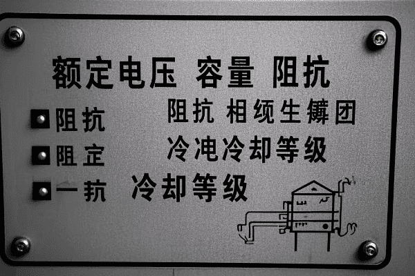
Transformer nameplates contain essential information including voltage ratings, capacity, impedance, cooling class, and connection diagrams. Understanding how to extract and interpret this data from diagrams is vital for proper transformer selection, installation, and operation.
Let’s break down the key elements you’ll find on a transformer nameplate diagram:
Voltage Ratings
This is one of the most critical pieces of information.
Voltage Information:
- Primary voltage
- Secondary voltage
- Tap voltages (if applicable)
I once saw a serious installation error due to misreading voltage ratings on a nameplate. Always double-check these values, as they’re fundamental to proper transformer application.
Capacity Rating
This indicates the transformer’s power handling capability.
Capacity Elements:
- kVA or MVA rating
- Continuous rating vs. short-time ratings
- Different ratings for various cooling modes
Impedance
Impedance is crucial for system calculations.
Impedance Data:
- Percentage impedance
- X/R ratio (sometimes provided)
- Important for fault current calculations
Cooling Class
This indicates the transformer’s cooling method.
Cooling Classifications:
- ONAN (Oil Natural Air Natural)
- ONAF (Oil Natural Air Forced)
- OFAF (Oil Forced Air Forced)
- Combinations of the above
Connection Diagram
A simplified representation of the transformer’s internal connections.
Diagram Elements:
- Winding configurations (e.g., Delta, Wye)
- Vector group (e.g., Dyn11)
- Neutral point indications
| Nameplate Item | Typical Format | Importance |
|---|---|---|
| Voltage Ratings | HV/LV in kV | Critical for proper application |
| Capacity | kVA or MVA | Determines load handling capability |
| Impedance | Percentage | Essential for system calculations |
| Cooling Class | ONAN, ONAF, etc. | Indicates cooling method and capacity |
| Connection Diagram | Schematic | Shows internal configuration |
In my experience, one of the most overlooked aspects of nameplate information is the relationship between cooling class and capacity. I’ve seen cases where engineers didn’t realize that the full rated capacity was only available with all cooling stages active. This can lead to overloading and reduced transformer life.
Another critical element is the vector group notation. This compact code (e.g., Dyn11) provides crucial information about the phase relationships between primary and secondary windings. I always emphasize the importance of understanding this notation, as it’s essential for proper transformer paralleling and system protection.
Don’t overlook the importance of tap information on the nameplate. Many transformers have multiple tap settings, and understanding the available voltage adjustments can be crucial for maintaining proper system voltage. I remember a case where incorrect tap setting led to persistent overvoltage issues in a distribution system.
It’s also important to pay attention to any special notations or footnotes on the nameplate. These can include important information about altitude derating, temperature rise limits, or special operating conditions. I’ve seen cases where ignoring these notes led to improper application and premature transformer failure.
Lastly, always cross-reference the nameplate information with the actual transformer diagram and physical unit. Discrepancies can occur, and it’s crucial to verify that the nameplate accurately represents the transformer you’re working with.
Understanding how to extract and interpret vital information from transformer nameplate diagrams is a fundamental skill for any electrical engineer. This knowledge is essential for everything from initial transformer selection to ongoing maintenance and troubleshooting. By mastering this skill, you’ll be better equipped to ensure the safe and efficient operation of your power distribution systems.
Protective Device Integration: Illustrating Safety Mechanisms in Transformer Schematics?
Are you confident in your ability to identify all the protective devices in a transformer schematic? Overlooking even one safety mechanism can lead to catastrophic failures.
Transformer schematics illustrate various protective devices including surge arresters, fuses, circuit breakers, and temperature monitors. Understanding how these devices are integrated and represented is crucial for ensuring transformer safety and reliability.

Let’s explore the key protective devices you’ll encounter in transformer schematics:
Surge Arresters
These devices protect against voltage spikes and lightning strikes.
Schematic Representation:
- Often shown as zigzag lines
- Typically connected to high voltage bushings
- May be present on both primary and secondary sides
I once reviewed a schematic where the surge arresters were improperly placed. This could have left the transformer vulnerable to damaging surges. Always check arrester positioning carefully.
Fuses and Circuit Breakers
These provide overcurrent protection.
Key Aspects:
- Fuses often represented as rectangles with a line through them
- Circuit breakers shown as squares with open/close symbols
- Ratings and types should be clearly indicated
Temperature Monitoring Devices
These prevent overheating damage.
Common Indicators:
- Thermometer symbols
- Often connected to alarm and trip circuits
- May control cooling system activation
Pressure Relief Devices
These prevent tank rupture due to internal pressure buildup.
Schematic Elements:
- Usually shown as a circle with an arrow
- Connected to alarm systems
- May be linked to rapid depressurization systems
Differential Protection
This detects internal faults by comparing currents.
Representation:
- Often shown as interconnected CT (Current Transformer) symbols
- Connected to a relay device
- Typically used in larger transformers
| Protective Device | Symbol | Function |
|---|---|---|
| Surge Arrester | Zigzag Line | Overvoltage protection |
| Fuse/Circuit Breaker | Rectangle/Square | Overcurrent protection |
| Temperature Monitor | Thermometer Icon | Overheating prevention |
| Pressure Relief | Circle with Arrow | Tank rupture prevention |
| Differential Protection | Interconnected CTs | Internal fault detection |
In my years of experience, I’ve found that one of the most commonly overlooked aspects of protective device integration is the coordination between different protection mechanisms. For instance, I once saw a case where the overcurrent protection wasn’t properly coordinated with the transformer’s thermal limits, leading to nuisance tripping under heavy, but allowable, loads.
Another critical aspect is understanding how protective devices interact with the transformer’s cooling system. In many schematics, you’ll see temperature monitors directly linked to cooling fan controls. I always advise engineers to trace these connections carefully to ensure proper thermal management.
Don’t forget about the importance of grounding in protection schemes. Many schematics will show ground connections for surge arresters and other devices. Proper grounding is crucial for the effectiveness of these protective measures.
It’s also important to consider the protection of auxiliary systems. Things like tap changers and cooling pumps often have their own protective devices, which should be clearly represented in the schematic. I’ve seen cases where failures in these auxiliary systems led to major transformer issues.
Lastly, pay attention to any backup or redundant protection systems shown in the schematic. In critical applications, redundancy in protection is often employed. Understanding these backup systems is crucial for ensuring continuous, reliable operation.
Interpreting protective device integration in transformer schematics is more than just identifying symbols. It’s about understanding how these devices work together to create a comprehensive safety system. By mastering this aspect of transformer diagrams, you’ll be better equipped to design, maintain, and troubleshoot these critical components of our power infrastructure.
Diagram Standards: Industry Conventions for Pad Mounted Transformer Drawings?
Have you ever wondered why transformer diagrams look so similar across different manufacturers? This consistency comes from industry-wide standards and conventions.
Pad mounted transformer drawings follow specific industry standards such as IEEE C57.12.00 and IEC 60076. These standards ensure consistency in representation, making diagrams universally understandable across different manufacturers and regions.
Let’s explore the key standards and conventions used in pad mounted transformer drawings:
IEEE Standards
IEEE standards are widely used in North America.
Key IEEE Standards:
- IEEE C57.12.00 for general requirements
- IEEE C57.12.34 for pad mounted transformers
- IEEE C57.12.10 for safety requirements
I once worked on an international project where confusion arose due to mixing IEEE and IEC standards. Always clarify which standard is being used to avoid misinterpretations.
IEC Standards
IEC standards are more common internationally.
Important IEC Standards:
- IEC 60076 for power transformers
- IEC 61936 for power installations
- IEC 60071 for insulation coordination
Symbol Standardization
Consistent use of symbols is crucial for clear communication.
Standardized Symbols:
- Winding representations
- Switch and breaker symbols
- Bushing and terminal symbols
Layout Conventions
Standard layouts help in quick interpretation.
Common Layout Practices:
- High voltage side typically on the left
- Low voltage side on the right
- Core representation in the center
Dimensional Standards
These ensure physical compatibility.
Dimensional Aspects:
- Standard enclosure sizes
- Bushing height and spacing
- Minimum clearances
| Standard Type | Example | Purpose |
|---|---|---|
| IEEE | C57.12.00 | General requirements (North America) |
| IEC | 60076 | Power transformer standards (International) |
| Symbol | IEEE 315 | Graphic symbols for diagrams |
| Layout | Industry Practice | Consistent arrangement of components |
| Dimensional | ANSI C57.12.34 | Physical specifications for pad mounted transformers |
In my experience, one of the most critical aspects of understanding diagram standards is recognizing regional variations. While there’s a push for global standardization, you’ll still encounter differences between North American and European practices. I always advise engineers to familiarize themselves with both IEEE and IEC standards for a comprehensive understanding.
Another important consideration is the level of detail in standardized diagrams. Some standards call for highly detailed representations, while others allow for more schematic approaches. I’ve seen cases where misunderstandings arose from different expectations of diagram detail.
Don’t overlook the importance of note conventions in standardized diagrams. Many standards specify how additional information should be presented, including test data, special operating conditions, and manufacturer-specific details. Proper interpretation of these notes is often as important as understanding the graphical elements.
It’s also crucial to stay updated on evolving standards. I remember a case where an older transformer design didn’t meet updated safety clearance standards, leading to installation issues. Regularly reviewing the latest standards publications is a must for any engineer working with transformer diagrams.
Lastly, consider the impact of digital transformation on diagram standards. With the increasing use of CAD and BIM systems, there’s a growing need for standardization in digital representations. I’ve been involved in projects where ensuring compatibility between different software platforms was a major challenge.
Understanding and adhering to industry conventions for pad mounted transformer drawings is essential for clear communication and safe, efficient design and installation. By mastering these standards, you’ll be better equipped to work with transformers from various manufacturers and in different global contexts.
From Blueprint to Reality: Utilizing Transformer Diagrams for Installation and Maintenance?
Have you ever struggled to translate a transformer diagram into real-world application? This final step from paper to practice is where many engineers face challenges.
Transformer diagrams are essential tools for installation and maintenance, providing crucial information on component layout, connections, and specifications. Proper interpretation and application of these diagrams ensure correct installation, efficient maintenance, and safeoperation of pad mounted transformers.
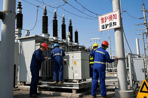
Let’s explore how to effectively use transformer diagrams in real-world scenarios:
Installation Guidance
Diagrams provide critical information for proper transformer setup.
Key Installation Aspects:
- Foundation requirements
- Clearance specifications
- Cable entry points
- Grounding locations
I once witnessed an installation where misinterpreting the cable entry points led to improper routing and potential safety hazards. Always double-check these details against the diagram.
Connection Verification
Ensuring correct connections is crucial for transformer operation.
Connection Checklist:
- Primary and secondary bushing connections
- Grounding connections
- Auxiliary equipment wiring (e.g., fans, temperature sensors)
Maintenance Planning
Diagrams are invaluable for planning and executing maintenance tasks.
Maintenance Uses:
- Identifying component locations
- Understanding access points for inspections
- Planning for oil sampling and testing
Troubleshooting Aid
When issues arise, diagrams are essential for efficient problem-solving.
Troubleshooting Applications:
- Tracing electrical paths
- Locating potential fault points
- Understanding protection scheme logic
Modification and Upgrades
Diagrams guide the process of modifying or upgrading transformers.
Modification Considerations:
- Identifying spaces for additional components
- Understanding impact on existing systems
- Ensuring compatibility with current setup
| Diagram Use | Practical Application | Benefit |
|---|---|---|
| Installation | Component placement | Ensures correct setup |
| Connections | Wiring verification | Prevents connection errors |
| Maintenance | Access point identification | Facilitates efficient servicing |
| Troubleshooting | Fault tracing | Speeds up problem resolution |
| Modifications | Upgrade planning | Guides safe and effective changes |
In my years of experience, I’ve found that one of the most critical skills in using transformer diagrams is the ability to visualize the 3D reality from a 2D representation. I remember a case where an engineer struggled to locate a specific component during maintenance because they couldn’t mentally translate the diagram to the physical transformer. Practice and hands-on experience are key to developing this skill.
Another important aspect is understanding the limitations of diagrams. While they provide crucial information, they don’t always capture every detail of the physical unit. I always advise technicians to use the diagram as a guide but to also rely on their observations and measurements of the actual transformer.
Don’t underestimate the importance of keeping diagrams updated. I’ve seen cases where modifications were made to transformers but not reflected in the diagrams, leading to confusion and potential safety issues during future maintenance. Establishing a system for updating and version control of diagrams is crucial.
It’s also vital to consider the skill level of the personnel using the diagrams. What might be clear to an experienced engineer could be confusing to a newer technician. I often recommend creating supplementary guides or annotations for complex diagrams to ensure they’re useful for all skill levels.
Lastly, integrating digital technologies can enhance the use of transformer diagrams in the field. I’ve been involved in projects where augmented reality (AR) was used to overlay diagram information onto the physical transformer, greatly aiding in installation and maintenance tasks.
Effectively utilizing transformer diagrams for installation and maintenance is a skill that combines technical knowledge, practical experience, and spatial reasoning. By mastering this skill, you can ensure that the transformers you work with are installed correctly, maintained efficiently, and operate safely throughout their lifespan.
Conclusion
Pad mounted transformer diagrams are essential tools for electrical engineers, providing crucial information for design, installation, maintenance, and troubleshooting. By understanding component representations, safety features, connection configurations, and industry standards, engineers can ensure the efficient and safe operation of these vital power distribution components.
