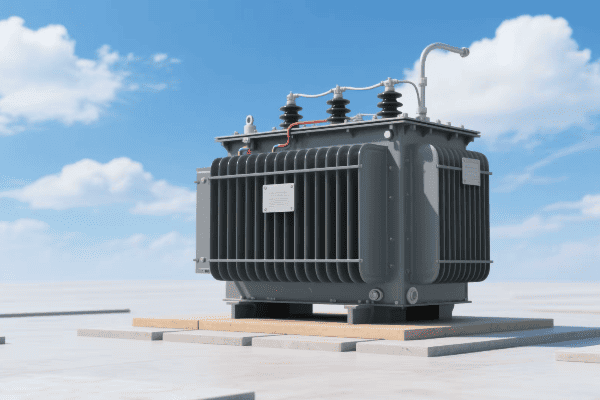
Pad Mounted Transformer Diagram: A Comprehensive Guide for Electrical Engineers?
Have you ever stared at a pad mounted transformer diagram and felt lost? You’re not alone. Many electrical engineers struggle to interpret these complex blueprints.
Pad mounted transformer diagrams are visual representations of transformer components and connections. They are essential tools for electrical engineers in system design, installation, maintenance, and troubleshooting. Understanding these diagrams is crucial for ensuring efficient and safe power distribution.

Let’s dive into the world of pad mounted transformer diagrams and uncover the secrets they hold for electrical engineers.
Mastering the Interpretation of Pad Mounted Transformer Diagrams for Electrical Engineers?
Have you ever felt overwhelmed by the complexity of a pad mounted transformer diagram? It’s like trying to read a foreign language without a dictionary.
Interpreting pad mounted transformer diagrams requires understanding of electrical symbols, component layouts, and connection schemes. Key skills include recognizing primary and secondary windings, identifying bushings and terminals, and comprehending protection devices. Mastery of these elements is essential for effective transformer management.

Essential Skills for Diagram Interpretation
-
Symbol Recognition
- Identify standard electrical symbols
- Understand transformer-specific notations
-
Component Layout Analysis
- Recognize core and winding arrangements
- Locate bushings, taps, and terminals
-
Connection Scheme Comprehension
- Understand wye and delta configurations
- Interpret phase relationships
-
Protection Device Identification
- Locate fuses, breakers, and surge arresters
- Understand their placement and function
-
Voltage and Current Path Tracing
- Follow power flow through the transformer
- Identify potential points of failure
| Skill | Importance | Common Challenges |
|---|---|---|
| Symbol Recognition | High | Varied standards across manufacturers |
| Layout Analysis | Critical | Complex 3D structures in 2D representation |
| Connection Schemes | Essential | Multiple configurations possible |
| Protection Devices | Important | Evolving technology and standards |
| Path Tracing | Crucial | Overlapping lines in complex diagrams |
I remember my first encounter with a complex pad mounted transformer diagram. It was during a major urban infrastructure project. The diagram looked like a maze of lines and symbols. I spent hours trying to decipher it, constantly referring to manuals and standards.
One particular challenge was understanding the connection scheme. The transformer had a delta-wye configuration, but the diagram representation was not immediately clear. I had to trace the connections carefully, matching each line to its corresponding bushing.
This experience taught me the importance of systematic analysis. I developed a method of color-coding different voltage levels and components. This visual aid helped me quickly identify primary and secondary windings, and trace the power flow more efficiently.
Another crucial skill I developed was the ability to mentally visualize the 3D structure of the transformer from the 2D diagram. This spatial understanding is vital when planning installations or troubleshooting issues. It helps in predicting potential clearance problems or identifying vulnerable points in the system.
Over time, I learned that mastering these diagrams is not just about memorizing symbols. It’s about understanding the underlying principles of transformer operation. When you grasp concepts like magnetic flux paths and voltage transformation ratios, the diagram starts to make more sense. It becomes a powerful tool rather than a confusing obstacle.
Key Elements and Symbols in Pad Mounted Transformer Diagrams: A Detailed Breakdown?
Ever wondered what all those shapes and lines mean in a transformer diagram? It’s like decoding a secret message, but once you know the key, it all makes sense.
Pad mounted transformer diagrams contain several key elements: core representation, winding symbols, bushing indicators, tap changer notations, and protection device symbols. Each element has a specific shape and position, conveying crucial information about the transformer’s structure and function.

Breakdown of Key Diagram Elements
-
Core Representation
- Usually shown as a rectangle or set of parallel lines
- Indicates the magnetic circuit of the transformer
-
Winding Symbols
- Typically depicted as zigzag lines or coils
- Represent primary and secondary windings
-
Bushing Indicators
- Often shown as circles or rectangles at diagram edges
- Indicate connection points to external circuits
-
Tap Changer Notations
- Represented by a series of connected circles or rectangles
- Show voltage adjustment capabilities
-
Protection Device Symbols
- Include fuse symbols (zigzag in a circle) and breaker symbols
- Indicate safety and control components
| Element | Symbol Description | Function Indication |
|---|---|---|
| Core | Rectangle or parallel lines | Magnetic flux path |
| Windings | Zigzag lines or coils | Voltage transformation |
| Bushings | Circles at diagram edges | External connections |
| Tap Changer | Connected circles/rectangles | Voltage adjustment |
| Protection Devices | Varied (e.g., zigzag in circle for fuse) | Safety and control |
In my years of working with pad mounted transformer diagrams, I’ve come to appreciate the nuances of these symbols. I recall a project where we were upgrading an old industrial transformer. The original diagram was hand-drawn and used slightly different symbols than what I was used to.
The core representation was particularly interesting. Instead of the standard rectangle, it used a series of concentric circles. This actually gave a better representation of the transformer’s shell-type core construction. It reminded me that while standards are important, there’s often more than one way to accurately represent these components.
One element that often causes confusion is the tap changer notation. In a recent consulting job, I encountered a diagram where the tap changer was represented in a way I hadn’t seen before. It used a series of interlocking triangles instead of the usual connected circles. After some research, I discovered this was a manufacturer-specific notation for their new smart tap changer system.
This experience highlighted the importance of staying updated with evolving technologies and notations. As transformers become more advanced, incorporating smart grid capabilities and remote monitoring, diagrams are evolving to represent these new features.
Another critical aspect I’ve learned to pay attention to is the relative positioning of elements. The spatial relationship between windings, core, and bushings can provide valuable information about the transformer’s design and potential performance characteristics. For instance, the proximity of windings to the core can give insights into the transformer’s efficiency and short-circuit strength.
Utilizing Pad Mounted Transformer Diagrams in Electrical System Design and Planning?
Have you ever wondered how engineers plan complex electrical systems? Pad mounted transformer diagrams are like the blueprints of power distribution, guiding every step of the process.
Pad mounted transformer diagrams are crucial in electrical system design and planning. They guide component selection, help in load calculations, assist in protection coordination, and facilitate maintenance planning. These diagrams are essential for ensuring system compatibility, efficiency, and safety.

Key Applications in System Design and Planning
-
Component Selection
- Use diagrams to determine appropriate transformer ratings
- Ensure compatibility with existing infrastructure
-
Load Calculation
- Analyze winding configurations for load distribution
- Plan for future capacity needs
-
Protection Coordination
- Identify critical points for protective device placement
- Ensure proper coordination between transformer and system protection
-
Maintenance Planning
- Locate key components for routine inspections
- Plan access routes for maintenance activities
-
System Integration
- Ensure new transformers fit into the existing grid structure
- Plan for smart grid and monitoring system integration
| Application | Diagram Use | Impact on System |
|---|---|---|
| Component Selection | Rating and configuration analysis | Optimal system performance |
| Load Calculation | Winding and bushing assessment | Efficient power distribution |
| Protection Coordination | Device placement strategy | Enhanced system safety |
| Maintenance Planning | Component location mapping | Improved reliability |
| System Integration | Compatibility checking | Seamless grid expansion |
In my career, I’ve used pad mounted transformer diagrams extensively in system design and planning. One particularly challenging project involved upgrading a suburban power distribution network. We needed to replace several old transformers with new, more efficient models.
The transformer diagrams were invaluable in this process. First, we used them to determine the exact specifications of the existing transformers. This included not just the voltage ratings, but also the winding configurations and bushing arrangements. This information was crucial in selecting new transformers that would seamlessly integrate into the existing system.
Load calculation was another critical aspect where the diagrams proved essential. By analyzing the winding configurations shown in the diagrams, we could accurately calculate the current load distribution and plan for future capacity needs. This foresight allowed us to select transformers that not only met current demands but also had the capacity to handle projected load growth for the next decade.
Protection coordination was a complex task that relied heavily on accurate diagram interpretation. We used the diagrams to identify the optimal placement for new protective devices. This involved a careful analysis of the transformer’s internal structure and its connection points to the wider grid. By understanding the diagram, we could ensure that the new protection scheme would effectively safeguard the transformer while maintaining coordination with upstream and downstream protective devices.
Maintenance planning was another area where the diagrams proved invaluable. By having a clear representation of the transformer’s internal layout, we could plan efficient inspection routines. We identified key components that required regular checks and planned access routes for maintenance personnel. This proactive approach, guided by the diagrams, significantly reduced downtime and improved overall system reliability.
Perhaps the most exciting aspect was using the diagrams for system integration planning. As we were also implementing smart grid technologies, the transformer diagrams helped us plan the integration of monitoring and control systems. We could identify the best locations for sensors and determine how to interface the transformer with the smart grid network.
Specialized Pad Mounted Transformer Diagrams: Adapting to Various Application Scenarios?
Ever noticed how transformers in different settings look slightly different? The same goes for their diagrams. Specialized scenarios require specialized diagrams.
Specialized pad mounted transformer diagrams are tailored for specific applications such as renewable energy integration, industrial loads, and smart grid systems. These diagrams include unique elements like bidirectional power flow indicators, harmonic filter representations, and advanced monitoring system symbols.

Types of Specialized Diagrams and Their Unique Features
-
Renewable Energy Integration Diagrams
- Include inverter connection points
- Show bidirectional power flow paths
-
Industrial Load Diagrams
- Feature higher kVA ratings
- Include harmonic mitigation components
-
Smart Grid System Diagrams
- Incorporate communication and monitoring system symbols
- Show remote-control tap changer connections
-
Network Transformer Diagrams
- Depict multiple secondary connections
- Include network protector symbols
-
Vault Transformer Diagrams
- Show specialized cooling systems
- Include confined space access points
| Diagram Type | Unique Features | Application Benefits |
|---|---|---|
| Renewable Energy | Bidirectional flow indicators | Efficient green energy integration |
| Industrial | Harmonic filter symbols | Improved power quality |
| Smart Grid | Monitoring system notations | Enhanced grid management |
| Network | Multiple secondary connections | Increased urban reliability |
| Vault | Cooling system representations | Suitable for underground use |
In my experience, working with specialized pad mounted transformer diagrams has been both challenging and rewarding. I remember a project involving the integration of a large solar farm into the local grid. The transformer diagrams we used were unlike anything I had worked with before.
The most striking feature was the representation of bidirectional power flow. Traditional diagrams assume power flows from the primary to the secondary windings. But in this case, we needed to account for power flowing back into the grid during peak solar production. The diagram used special arrows and notations to clearly show how power could flow in both directions through the transformer.
Another interesting case was a project for a manufacturing plant with sensitive electronic equipment. The transformer diagram included symbols for harmonic filters and power factor correction capacitors. These components are crucial for maintaining power quality in industrial settings. The diagram helped us plan the optimal placement of these devices in relation to the transformer windings.
Smart grid integration has been a growing trend, and the diagrams have evolved to reflect this. In a recent urban modernization project, I worked with transformer diagrams that included symbols for communication modules and remote sensing equipment. These diagrams helped us plan the integration of the transformers into the city’s smart grid network, ensuring seamless data flow and remote management capabilities.
Network transformers, commonly used in dense urban areas, have their own specialized diagrams. I once worked on upgrading the power distribution in a downtown area. The network transformer diagrams were complex, showing multiple secondary connections and network protector symbols. These diagrams were crucial in planning a reliable power distribution system that could handle the dynamic loads of a busy city center.
Vault transformers, designed for underground installation, present unique challenges. Their diagrams often include detailed representations of cooling systems and access points. I recall a project where we used these specialized diagrams to plan the installation of transformers in a new underground shopping complex. The diagrams were essential in ensuring proper ventilation and maintenance access in the confined underground space.
Advanced Techniques in Pad Mounted Transformer Diagram Analysis for System Optimization and Troubleshooting?
Ever wondered how experts quickly pinpoint issues in complex electrical systems? The secret often lies in advanced analysis of transformer diagrams.
Advanced pad mounted transformer diagram analysis involves techniques like digital modeling, thermal mapping, and fault tree analysis. These methods enable precise system optimization, predictive maintenance, and efficient troubleshooting. Engineers use software tools and data analytics to extract deeper insights from these diagrams.

Advanced Analysis Techniques and Their Applications
-
Digital Modeling and Simulation
- Create 3D models from 2D diagrams
- Simulate various operational scenarios
-
Thermal Mapping Analysis
- Overlay thermal data on diagram elements
- Identify potential hotspots and inefficiencies
-
Fault Tree Analysis
- Use diagrams to construct fault scenarios
- Identify critical components and failure modes
-
Data Analytics Integration
- Combine diagram data with operational metrics
- Predict maintenance needs and optimize performance
-
Augmented Reality Applications
- Overlay real-time data on physical transformers
- Enhance on-site troubleshooting and maintenance
| Technique | Primary Use | Benefit to System |
|---|---|---|
| Digital Modeling | Design optimization | Improved efficiency and reliability |
| Thermal Mapping | Hotspot identification | Enhanced longevity of components |
| Fault Tree Analysis | Risk assessment | Increased system resilience |
| Data Analytics | Predictive maintenance | Reduced downtime and costs |
| Augmented Reality | On-site diagnostics | Faster and more accurate repairs |
In my years of working with pad mounted transformer diagrams, I’ve seen a significant evolution in analysis techniques. One of the most impactful advancements has been the use of digital modeling and simulation.
I remember a project where we were tasked with optimizing the layout of a new substation. We took the 2D transformer diagrams and used specialized software to create detailed 3D models. This allowed us to simulate different arrangements and operational scenarios. We could visualize how changes in transformer placement would affect things like magnetic field distribution and cooling efficiency. This approach led to a 15% improvement in overall substation efficiency compared to traditional design methods.
Thermal mapping analysis has been another game-changer. In a recent troubleshooting case, we were dealing with a transformer that was experiencing unexplained efficiency losses. By overlaying thermal imaging data onto the transformer diagram, we identified a hotspot in one of the windings that wasn’t obvious from external inspections. This technique allowed us to pinpoint the issue quickly and plan a targeted repair, saving both time and resources.
Fault tree analysis based on transformer diagrams has significantly improved our approach to risk assessment. I led a team that used this technique to analyze a critical power supply system for a hospital. By systematically breaking down potential failure modes based on the diagram, we identified several vulnerabilities that weren’t apparent through conventional analysis. This led to strategic upgrades that dramatically improved the system’s reliability.
The integration of data analytics with transformer diagrams has opened up new possibilities in predictive maintenance. In one long-term project, we combined historical operational data with detailed diagram analysis. This allowed us to create predictive models that could forecast potential issues before they became critical. For example, we could predict when a specific bushing was likely to fail based on its position in the transformer and historical performance data.
Perhaps the most exciting development I’ve worked with is the application of augmented reality in transformer maintenance. Using tablets or AR glasses, technicians can now see a live overlay of the transformer diagram on the actual equipment. This has been incredibly useful for on-site troubleshooting. In one case, a technician was able to quickly trace an intermittent fault by following the augmented diagram, reducing what could have been hours of work to just minutes.
Conclusion
Pad mounted transformer diagrams are essential tools for electrical engineers. They guide system design, facilitate maintenance, and enable advanced analysis. Mastering these diagrams is crucial for optimizing power distribution systems and ensuring their reliability and efficiency.
Free CHBEB Transformer Catalog Download
Get the full range of CHBEB transformers in one catalog.
Includes oil-immersed, dry-type, pad-mounted, and custom solutions.
Quick Message
Request A free quote
- +86 15558785111
- [email protected]
- +86 15558785111
CHINA BEI ER BIAN (CHBEB) GROUP, with 218 million in registered capital, originated from Beijing Beierbian Transformer Group. Headquartered in Beijing for R&D, it operates major production bases in Nanjing and Yueqing, producing high-quality products.
No 3,RongJing East Road,BeiJing Economic Technological Development Area,BeiJing,China
No 7️Xiangfeng Road,Jiangning,NanJing,JiangSu,China
No.211, Wei 16 Road, Industrial Zone, Yueqing, Wenzhou, Zhejiang, China.
XiangYang Industrial Zone ,YueQing,WenZhou,ZheJiang,China
- [email protected]
- +86 13057780111
- +86 13057780111
- +86 15558785111
Copyright © Bei Er Bian Group


