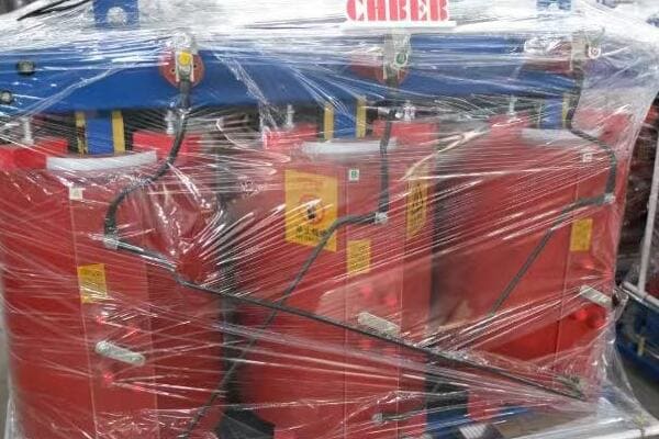
Top 5 Installation Mistakes with Dry Type Transformers—and How to Avoid Them?
Are you worried about potential issues with your dry type transformer installation? You’re not alone. Many engineers and technicians face challenges when setting up these crucial pieces of equipment. But what if you could avoid the most common pitfalls and ensure a flawless installation?
Improper ventilation, grounding, cable termination, and installation in unsuitable environments are common mistakes when setting up dry-type transformers. This guide outlines the top 5 errors and shows how to prevent them—ensuring safer operation, longer service life, and compliance with electrical standards.
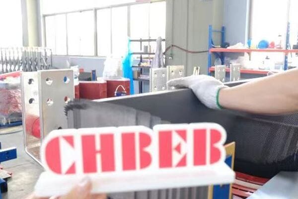
In this comprehensive guide, I’ll walk you through the five most common installation mistakes I’ve encountered in my years of experience with dry type transformers. More importantly, I’ll provide you with practical solutions to avoid these errors, ensuring your transformer operates safely and efficiently for years to come.
Mistake #1 – Ignoring Ventilation Requirements
Have you ever wondered why some transformers overheat even when they’re not overloaded? The answer often lies in poor ventilation. But why is proper airflow so crucial for dry type transformers, and how can you ensure your installation doesn’t fall into this common trap?
Adequate ventilation is critical for dry type transformers to dissipate heat effectively. Ignoring clearance requirements or obstructing airflow can lead to overheating, reduced efficiency, and premature failure. Proper installation requires following IEC 60076-11 specifications for air gaps and avoiding placement in sealed rooms or near heat sources.
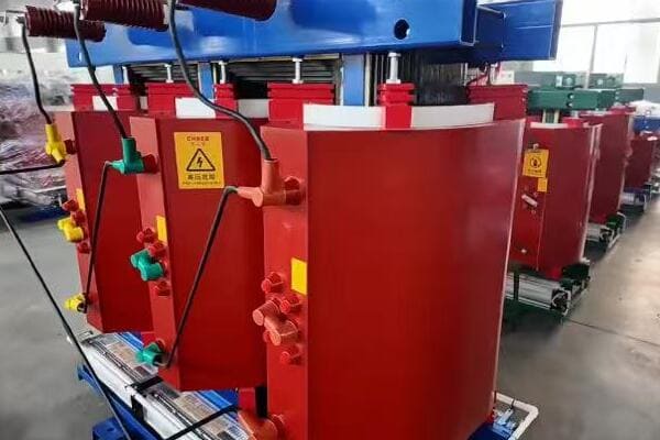
Key Ventilation Considerations
To ensure proper cooling of your dry type transformer, keep these points in mind:
- Transformers need minimum clearance on all sides
- Obstructed airflow = overheating risk
- Avoid placing in sealed rooms or near heat sources
- Follow IEC 60076-11 air gap specs
Understanding Clearance Requirements
Proper clearance is essential for effective heat dissipation:
- Top clearance: Usually the most critical, as heat rises
- Side clearances: Allow for convection currents
- Bottom clearance: Ensures air intake isn’t obstructed
I once consulted on a project where a transformer was installed in a tight utility closet. Despite being correctly sized for the load, it consistently overheated. The problem? Insufficient clearance on all sides, restricting airflow. We solved the issue by relocating the transformer to a more spacious area, immediately resolving the overheating problems.
Avoiding Airflow Obstructions
Even with proper clearance, obstructions can impede cooling:
- Keep areas around the transformer free of stored items
- Ensure ventilation openings in enclosures are not blocked
- Consider the impact of nearby equipment on air circulation
In a recent industrial installation, we discovered that large storage shelves had been placed too close to the transformer, blocking airflow on one side. This simple oversight led to localized overheating. Rearranging the storage area to maintain proper clearances solved the issue.
Environmental Considerations
The transformer’s environment plays a crucial role in cooling efficiency:
- Avoid sealed rooms without proper ventilation systems
- Be cautious of installing near heat-generating equipment
- Consider ambient temperature fluctuations in the installation area
I recall a data center project where a dry type transformer was initially placed near a bank of servers. The combined heat output created a hot spot, compromising the transformer’s efficiency. Relocating the transformer to a cooler area of the facility significantly improved its performance and lifespan.
Compliance with IEC 60076-11
Following international standards ensures optimal performance:
- Adhere to specified minimum clearances
- Consider using forced air cooling for high-load applications
- Regularly inspect and maintain ventilation systems
Here’s a quick reference table for typical clearance requirements:
| Position | Minimum Clearance | Recommended Clearance |
|---|---|---|
| Top | 300 mm | 500 mm |
| Sides | 200 mm | 300 mm |
| Front | 600 mm | 1000 mm |
| Rear | 200 mm | 300 mm |
Note: These are general guidelines. Always consult your transformer’s specific installation manual for exact requirements.
By paying close attention to ventilation requirements, you’re not just avoiding a common installation mistake; you’re ensuring the longevity and efficiency of your dry type transformer. Proper airflow is the key to maintaining optimal operating temperatures, preventing premature insulation breakdown, and ultimately, safeguarding your investment in this critical piece of equipment.
Mistake #2 – Incorrect Grounding Connections
Have you ever wondered why proper grounding is so crucial for dry type transformers? Many installers underestimate its importance, leading to potential safety hazards and equipment damage. But what exactly constitutes correct grounding, and how can you ensure your installation meets the necessary standards?
Correct grounding is essential for the safety and proper operation of dry type transformers. Using designated grounding lugs, ensuring continuity between the enclosure and system ground, and avoiding the use of mounting bolts for grounding are key. Poor grounding can lead to high fault currents, electric shock risks, and equipment failure.
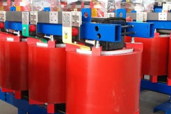
Essential Grounding Practices
To ensure proper grounding of your dry type transformer, keep these points in mind:
- Use designated grounding lugs, not mounting bolts
- Ensure continuity between enclosure and system ground
- Poor grounding = high fault current risk
Using Proper Grounding Points
Correct grounding starts with using the right connection points:
- Locate and use the designated grounding lugs or terminals
- Never rely on mounting bolts or structural components for grounding
- Ensure grounding points are clean and free of paint or corrosion
I once inspected a transformer installation where the technician had used a mounting bolt for grounding, assuming it provided a sufficient connection. This mistake could have led to dangerous voltage potentials on the transformer casing. We immediately corrected the issue by installing a proper ground connection to the designated lug.
Ensuring Ground Continuity
Continuity between the transformer enclosure and the system ground is crucial:
- Use appropriately sized grounding conductors
- Minimize the length of grounding cables to reduce impedance
- Regularly test ground continuity as part of maintenance routines
In a recent industrial project, we discovered intermittent ground faults. Upon investigation, we found that the grounding conductor was undersized for the application, leading to poor continuity. Upgrading to a larger gauge conductor resolved the issue and improved overall system safety.
Understanding the Risks of Poor Grounding
Inadequate grounding can lead to several serious issues:
- Increased risk of electric shock to personnel
- Potential for equipment damage during fault conditions
- Interference with sensitive electronic equipment
I recall a case where poor grounding led to mysterious equipment malfunctions in a nearby control room. The improperly grounded transformer was allowing stray currents to affect sensitive instrumentation. Correcting the grounding not only resolved the safety concern but also eliminated the operational issues.
Best Practices for Grounding Installation
Follow these guidelines to ensure proper grounding:
- Use copper conductors for grounding whenever possible
- Ensure all connections are tight and protected from corrosion
- Implement a regular inspection and testing schedule for ground connections
Here’s a quick reference table for grounding conductor sizing:
| Transformer kVA | Minimum Grounding Conductor Size (AWG/kcmil) |
|---|---|
| Up to 50 | 8 |
| 51-150 | 6 |
| 151-300 | 4 |
| 301-500 | 2 |
| Over 500 | 0 |
Note: Always consult local electrical codes and manufacturer specifications for exact requirements.
By paying close attention to grounding connections, you’re not just avoiding a common installation mistake; you’re ensuring the safety of personnel and the protection of your equipment. Proper grounding is fundamental to the safe and reliable operation of dry type transformers, providing a path for fault currents and helping to maintain stable voltage levels throughout your electrical system.
Mistake #3 – Improper Cable Termination
Are you confident that your transformer’s cable connections are secure and efficient? Many installers overlook the critical importance of proper cable termination, leading to potential hazards and performance issues. But what constitutes correct cable termination, and how can you ensure your installation meets the highest standards of safety and efficiency?
Proper cable termination is crucial for the safe and efficient operation of dry type transformers. This involves using the correct torque, avoiding cable stress, and ensuring clean, flush connections. Improper termination can lead to overheating, arcing, and even catastrophic failure of the transformer.
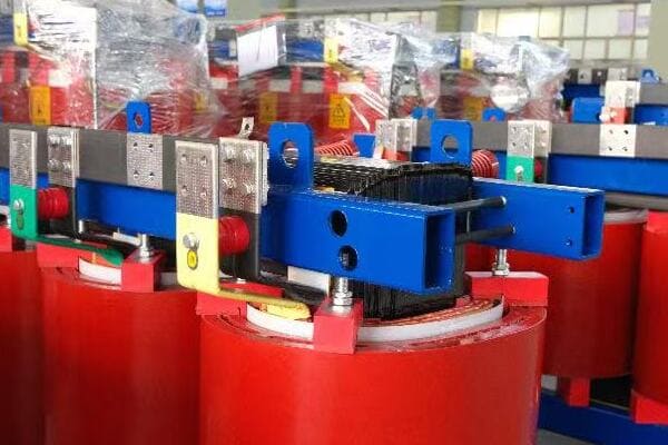
Key Aspects of Proper Cable Termination
To ensure correct cable termination for your dry type transformer, focus on these critical points:
- Use proper torque (as per terminal label)
- Avoid bending or stressing cable entries
- Ensure lug-to-bar contact is clean & flush
Applying Correct Torque
Using the right amount of torque is essential for secure connections:
- Always refer to the manufacturer’s specifications for torque values
- Use a calibrated torque wrench to achieve precise tightening
- Over-torquing can damage terminals, while under-torquing leads to loose connections
I once investigated a transformer failure where the primary cause was a loose connection due to under-torqued terminals. This simple oversight led to localized heating, eventually causing insulation breakdown and a costly outage. Since then, I always emphasize the importance of proper torque application in every installation.
Preventing Cable Stress
Proper cable management is crucial to prevent stress on terminations:
- Use appropriate cable support methods to reduce strain on connections
- Avoid sharp bends in cables, especially near termination points
- Allow sufficient slack in cables to accommodate thermal expansion and vibration
In a recent industrial installation, we observed premature cable insulation failure near the transformer terminals. Upon closer inspection, we found that the cables were installed with too tight a bend radius, causing stress and eventual breakdown. Rerouting the cables with proper support and gentler bends resolved the issue.
Ensuring Clean and Flush Connections
The quality of the physical connection is paramount:
- Clean all contact surfaces thoroughly before termination
- Ensure lugs are properly sized for the cable and terminal
- Verify that the lug-to-bar contact is flush and free of gaps
I recall a case where intermittent faults were traced back to contamination on the transformer terminals. A thin film of oil from the manufacturing process had been left on the terminals, preventing proper contact. A thorough cleaning and re-termination solved the problem, highlighting the importance of clean connections.
Best Practices for Cable Termination
Follow these guidelines to ensure optimal cable termination:
- Use compression lugs for larger cables to ensure better contact
- Implement a regular inspection schedule for all terminations
- Consider using infrared thermography to detect potential hot spots at connections
Here’s a quick reference table for common cable termination issues and solutions:
| Issue | Potential Consequences | Solution |
|---|---|---|
| Loose connections | Overheating, arcing | Apply correct torque, regular retightening |
| Contaminated surfaces | Poor contact, increased resistance | Clean thoroughly before termination |
| Improper lug size | Incomplete contact, overheating | Use correctly sized lugs for cable and terminal |
| Cable stress | Insulation damage, connection failure | Proper cable support and routing |
By paying close attention to cable termination details, you’re not just avoiding a common installation mistake; you’re ensuring the long-term reliability and safety of your dry type transformer. Proper termination is crucial for maintaining efficient power transfer, preventing localized heating, and ultimately, safeguarding your electrical system against failures and downtime.
Mistake #4 – Installing in Contaminated or Humid Locations
Have you considered how the environment affects your dry type transformer’s performance and lifespan? Many installers overlook the critical impact of location, leading to premature failures and reduced efficiency. But what exactly constitutes an unsuitable environment, and how can you ensure your transformer is protected against these challenges?
Installing dry type transformers in contaminated or humid environments without proper protection can lead to insulation degradation, reduced efficiency, and premature failure. Proper installation requires considering factors like air quality, humidity levels, and potential contaminants. Using appropriate enclosures or selecting transformers with enhanced environmental protection (e.g., E2, E3 ratings) is crucial for these challenging locations.
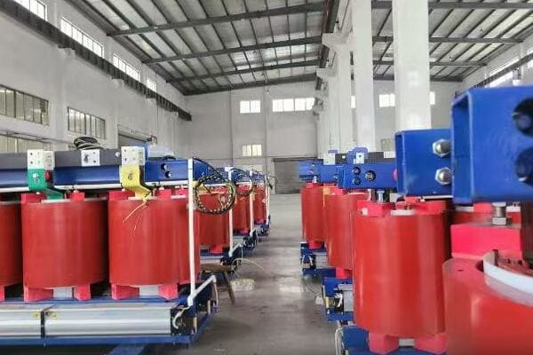
Key Considerations for Environmental Protection
When installing dry type transformers in challenging environments, keep these points in mind:
- Avoid corrosive gas/dust without E2 protection
- Use dry-type units with H-class resin for high humidity
- Add enclosures or filters if in industrial zones
Understanding Environmental Ratings
Dry type transformers come with different environmental protection ratings:
- E0: Basic protection, suitable for clean, dry environments
- E1: Light environmental protection
- E2: Enhanced protection against moisture and pollution
- E3: Highest level of protection for severe environments
I once consulted on a project where a standard E0-rated transformer was installed in a coastal industrial facility. Within months, we observed significant degradation due to salt air and industrial pollutants. Replacing it with an E2-rated unit resolved the issues and significantly extended the transformer’s lifespan.
Dealing with High Humidity
Humidity can be particularly challenging for dry type transformers:
- Consider using transformers with H-class insulation in high-humidity areas
- Implement dehumidification systems in transformer rooms if necessary
- Regular inspections for signs of moisture ingress are crucial
In a recent project in a tropical climate, we installed dry type transformers with H-class resin and additional enclosure ventilation. This combination effectively protected the units from the high ambient humidity, ensuring reliable operation in challenging conditions.
Protection Against Contaminants
Industrial environments often present risks from airborne contaminants:
- Use filtered enclosures in areas with high dust or particulate levels
- Consider sealed designs for environments with corrosive gases
- Regular cleaning and maintenance are essential in contaminated areas
I recall a case where a transformer in a cement plant was failing prematurely due to dust accumulation. We resolved the issue by installing a custom-designed filtered enclosure, which significantly improved the transformer’s performance and lifespan.
Best Practices for Challenging Environments
Follow these guidelines to protect your transformer in difficult conditions:
- Conduct a thorough environmental assessment before installation
- Choose the appropriate environmental rating based on the location
- Implement additional protective measures as needed (e.g., enclosures, filtration)
- Establish a rigorous maintenance schedule for transformers in harsh environments
Here’s a quick reference table for environmental considerations:
| Environmental Factor | Potential Impact | Protective Measure |
|---|---|---|
| High Humidity | Insulation degradation | H-class resin, dehumidification |
| Airborne Dust | Reduced cooling, insulation damage | Filtered enclosures, regular cleaning |
| Corrosive Gases | Accelerated component deterioration | Sealed designs, E2/E3 ratings |
| Salt Air | Corrosion of metal parts | Enhanced corrosion protection, E2/E3 ratings |
By carefully considering the installation environment and implementing appropriate protective measures, you’re not just avoiding a common mistake; you’re ensuring the longevity and reliability of your dry type transformer. Proper environmental protection is crucial for maintaining optimal performance, preventing premature failures, and ultimately, maximizing the return on your investment in this critical equipment.
Mistake #5 – Skipping Torque Checks and Final Testing
Are you confident that your newly installed dry type transformer is ready for safe, efficient operation? Many installers make the critical mistake of rushing through or completely skipping final checks and tests. But why are these final steps so crucial, and what risks do you run by overlooking them?
Skipping torque checks and final testing can lead to immediate failures or long-term reliability issues in dry type transformers. Proper installation requires verifying all connections with a torque wrench, performing insulation resistance tests, and conducting no-load tests before energization. These steps ensure safety, compliance, and optimal performance of the transformer.
Essential Final Checks and Tests
To ensure your dry type transformer is properly installed and ready for operation, focus on these critical steps:
- Check all terminals with torque wrench
- Perform insulation resistance tests
- Run no-load test before energization
- Document commissioning checklist
Importance of Torque Checks
Proper torque on all connections is crucial for safe and efficient operation:
- Use a calibrated torque wrench to verify all electrical connections
- Follow manufacturer’s specifications for torque values
- Re-check torque after initial heat cycles, as connections may loosen
I once investigated a transformer failure that occurred just weeks after installation. The root cause? A single loose connection that had been overlooked during final checks. This oversight led to localized heating, eventual arcing, and a costly shutdown. Since then, I always emphasize the critical importance of thorough torque checks as part of the final installation process.
Conducting Insulation Resistance Tests
Insulation resistance testing is crucial for verifying the integrity of the transformer’s insulation:
- Use a megohmmeter to test insulation resistance between windings and to ground
- Compare results to manufacturer’s specifications
- Investigate any unexpectedly low readings before energization
In a recent project, our insulation resistance test revealed unexpectedly low values. Further investigation uncovered moisture ingress during transportation. By identifying this issue before energization, we avoided potential insulation failure and were able to properly dry out the transformer before putting it into service.
Performing No-Load Tests
No-load testing provides valuable information about the transformer’s core performance:
- Measure input voltage, current, and power under no-load conditions
- Compare results to factory test reports
- Investigate any significant deviations from expected values
I recall a case where a no-load test revealed abnormally high current draw. This led us to discover a manufacturing defect in the core, which could have caused significant inefficiency and potential failure if not caught during this crucial test.
Documenting the Commissioning Process
Proper documentation is essential for future reference and maintenance:
- Create a comprehensive commissioning checklist
- Record all test results and observations
- Include photographs of key installation aspects
Here’s a sample commissioning checklist:
| Task | Verified (✔) | Notes |
|---|---|---|
| Clearance around unit | ☐ | |
| Grounding connections | ☐ | |
| Cable termination checked | ☐ | |
| Torque measurements | ☐ | |
| Insulation resistance test | ☐ | |
| No-load test | ☐ | |
| Visual inspection complete | ☐ |
Best Practices for Final Checks and Testing
Follow these guidelines to ensure thorough final checks:
- Allocate sufficient time for testing – rushing can lead to oversights
- Use calibrated test equipment for accurate results
- Have a second technician verify critical measurements
- Address any anomalies or unexpected results before energization
By meticulously performing these final checks and tests, you’re not just avoiding a common installation mistake; you’re ensuring the safety, reliability, and efficiency of your dry type transformer from day one. These steps are crucial for catching any issues that may have been overlooked during the installation process and provide a baseline for future maintenance and troubleshooting.
Installation Checklist for Dry Type Transformers
Are you looking for a comprehensive guide to ensure your dry type transformer installation is flawless? Look no further. This checklist covers all the critical steps you need to follow for a safe, efficient, and compliant installation.
A thorough installation checklist for dry type transformers includes verifying proper ventilation, correct grounding, secure cable terminations, environmental suitability, and comprehensive final testing. Following this checklist ensures optimal performance, safety compliance, and longevity of the transformer.
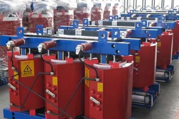
Complete Installation Checklist
Use this comprehensive checklist to guide your dry type transformer installation:
| Task | Verified (✔) | Notes |
|---|---|---|
| Ventilation and Clearance | ||
| Minimum clearance on all sides met | ☐ | |
| No obstructions to airflow | ☐ | |
| Room temperature within specs | ☐ | |
| Grounding | ||
| Proper grounding lug used | ☐ | |
| Grounding conductor sized correctly | ☐ | |
| Continuity to system ground verified | ☐ | |
| Cable Termination | ||
| Cables properly supported | ☐ | |
| Correct lugs used | ☐ | |
| Torque applied as per specs | ☐ | |
| Environmental Considerations | ||
| Transformer rating matches environment | ☐ | |
| Protection from contaminants in place | ☐ | |
| Humidity levels within acceptable range | ☐ | |
| Final Checks and Testing | ||
| All connections torque checked | ☐ | |
| Insulation resistance test performed | ☐ | |
| No-load test conducted | ☐ | |
| Visual inspection complete | ☐ | |
| Documentation | ||
| All test results recorded | ☐ | |
| Installation photos taken | ☐ | |
| Commissioning report completed | ☐ |
Using the Checklist Effectively
To make the most of this checklist:
- Review it before starting the installation to ensure you have all necessary tools and equipment.
- Use it as a step-by-step guide during the installation process.
- Have a second person verify each item for added safety and accuracy.
- Keep the completed checklist as part of your permanent installation records.
By following this comprehensive checklist, you’ll significantly reduce the risk of installation errors and ensure your dry type transformer is set up for optimal performance and longevity.
Conclusion
Avoiding these top 5 installation mistakes—improper ventilation, incorrect grounding, faulty cable termination, unsuitable environmental placement, and skipping final checks—is crucial for the safe and efficient operation of dry type transformers. By following the provided checklist and best practices, you can ensure a reliable, long-lasting installation that meets all safety and performance standards.
Remember, at chbeb-ele, we’re not just sharing information – we’re empowering you to be part of the solution in creating a secure, clean, and efficient energy future. Let’s continue this journey together.
Free CHBEB Transformer Catalog Download
Get the full range of CHBEB transformers in one catalog.
Includes oil-immersed, dry-type, pad-mounted, and custom solutions.
Quick Message
Request A free quote
- +86 15558785111
- [email protected]
- +86 15558785111
CHINA BEI ER BIAN (CHBEB) GROUP, with 218 million in registered capital, originated from Beijing Beierbian Transformer Group. Headquartered in Beijing for R&D, it operates major production bases in Nanjing and Yueqing, producing high-quality products.
No 3,RongJing East Road,BeiJing Economic Technological Development Area,BeiJing,China
No 7️Xiangfeng Road,Jiangning,NanJing,JiangSu,China
No.211, Wei 16 Road, Industrial Zone, Yueqing, Wenzhou, Zhejiang, China.
XiangYang Industrial Zone ,YueQing,WenZhou,ZheJiang,China
- [email protected]
- +86 13057780111
- +86 13057780111
- +86 15558785111
Copyright © Bei Er Bian Group

