Have you ever wondered what’s inside a transformer and how it actually works? You’re not alone. Many engineers and technicians find transformers mysterious, despite their crucial role in power systems. But what if you could understand these devices from the inside out?
Transformers consist of key electrical components including the magnetic core, windings, insulation, tap changers, and bushings. Each part plays a vital role in voltage regulation, energy transfer, and electrical safety. Understanding these elements helps in selecting, operating, and maintaining transformers efficiently.
In this comprehensive guide, I’ll walk you through the main components of a transformer, explaining their functions and how they work together. Whether you’re a seasoned engineer or just starting in the field, this article will deepen your understanding of these essential power system devices.
What Are the Main Parts of a Transformer?
Have you ever looked at a transformer and wondered what’s inside that metal box or tank? Understanding the main components is crucial for anyone working with electrical systems. But what exactly are these parts, and why are they so important?
**The main parts of a transformer include:
- Magnetic Core
- Primary & Secondary Windings
- Insulation System
- Tap Changer (if present)
- Bushing Terminals
- Tank / Enclosure (for oil type)**
Diving Deeper into Transformer Components
Let’s explore each of these components in more detail:
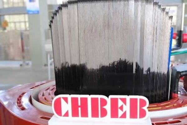
Magnetic Core
The core is the heart of the transformer:
- Made from thin laminations of silicon steel
- Provides a path for magnetic flux
- Crucial for energy transfer between windings
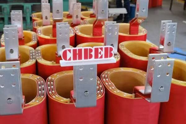
Primary & Secondary Windings
Windings are the transformer’s electrical conductors:
- Usually made of copper or aluminum
- Primary winding receives input voltage
- Secondary winding delivers output voltage
- Number of turns determines voltage transformation ratio
Insulation System
Insulation is critical for safety and efficiency:
- Prevents short circuits between windings and core
- Can be air, oil, or solid materials like resin
- Quality of insulation affects transformer lifespan
Tap Changer
Not all transformers have tap changers, but they’re important for voltage regulation:
- Allows adjustment of turns ratio
- Can be on-load or off-load type
- Critical for maintaining stable output voltage
Bushing Terminals
Bushings are the connection points to the outside world:
- Insulated passages for conductors
- Allow safe connection of high voltage cables
- Often made of porcelain or composite materials
Tank / Enclosure
For oil-filled transformers, the tank is crucial:
- Contains the insulating oil
- Provides structural support
- Helps in heat dissipation
I once worked on a project where we had to troubleshoot a faulty transformer. By understanding these components, we quickly identified that the issue was with the tap changer, not the core or windings as initially suspected. This knowledge saved significant time and resources in the repair process.
Understanding these main components is just the beginning. Each part plays a crucial role in the transformer’s operation and efficiency. In the following sections, we’ll dive deeper into each component, exploring their functions and importance in more detail.
Transformer Core: The Magnetic Heart of the Device
Have you ever wondered why transformer cores are so heavy and what makes them so special? The core is often called the heart of the transformer, but why is it so crucial to the device’s operation?
The transformer core is made from laminated silicon steel sheets, designed to guide magnetic flux efficiently. It reduces eddy current losses and plays a vital role in energy transfer. There are several core types, including shell-type, core-type, and toroidal, each with specific advantages for different applications.
Key Aspects of Transformer Cores
Let’s explore the critical features of transformer cores:
- Made from laminated silicon steel
- Guides magnetic flux efficiently
- Reduces eddy current losses
- Types: Shell-type, Core-type, Toroidal
Core Material and Construction
Transformer cores are typically made from silicon steel, also known as electrical steel:
- Silicon content reduces eddy current losses
- Laminated construction further minimizes losses
- Thickness of laminations can be as little as 0.23mm
I once visited a transformer manufacturing plant where I saw the meticulous process of assembling these cores. The precision required in stacking the laminations was impressive, highlighting the importance of core construction in transformer efficiency.
Magnetic Flux Guidance
The core’s primary function is to guide magnetic flux:
- Provides a low-reluctance path for magnetic fields
- Ensures efficient energy transfer between windings
- Shape and design optimize flux distribution
Eddy Current Loss Reduction
Minimizing eddy current losses is crucial for efficiency:
- Laminations break up eddy current paths
- Grain-oriented steel aligns magnetic domains
- Proper core design can significantly reduce overall losses
Types of Transformer Cores
Different core types suit various applications:
-
Shell-type Core:
- Windings surrounded by core material
- Good for high-current, low-voltage applications
-
Core-type:
- Core surrounded by windings
- Common in distribution transformers
-
Toroidal Core:
- Donut-shaped core with windings around the circumference
- Highly efficient, often used in small-scale applications
In a recent project, we had to choose between core-type and shell-type designs for a large power transformer. We opted for the shell-type due to its better short-circuit strength, which was crucial for the high-current application.
Core Performance Factors
Several factors influence core performance:
| Factor | Impact on Performance |
|---|---|
| Material Quality | Affects magnetic properties and losses |
| Lamination Thickness | Thinner laminations reduce eddy currents |
| Core Shape | Influences flux distribution and efficiency |
| Assembly Method | Affects overall magnetic circuit quality |
Understanding these core characteristics is essential for transformer design and selection. The core’s quality and design directly impact the transformer’s efficiency, size, and overall performance. In my experience, a well-designed core can make the difference between an average transformer and an exceptional one, especially in high-efficiency applications.
Windings: How Electricity Flows Through the Transformer
Have you ever wondered how transformers actually change voltage levels? The secret lies in the windings. But what exactly are these windings, and how do they perform this seemingly magical feat of voltage transformation?
Transformer windings are coils of wire, typically made of copper or aluminum, that carry the electric current. The number of turns in the primary and secondary windings determines the voltage ratio. These windings are insulated and designed to handle specific current loads, directly impacting the transformer’s efficiency and heat dissipation.
Key Aspects of Transformer Windings
Let’s explore the critical features of transformer windings:
- Made of copper or aluminum
- Determines voltage ratio
- Insulated with varnish or paper
- Impact efficiency & heat dissipation
Winding Materials
The choice of winding material is crucial:
- Copper: Higher conductivity, often used in high-performance transformers
- Aluminum: Lighter and less expensive, common in distribution transformers
I once worked on a project where we had to decide between copper and aluminum windings. We chose copper for its superior conductivity, which allowed for a more compact design in a space-constrained substation.
Voltage Ratio and Turns Ratio
The fundamental principle of transformer operation lies in the turns ratio:
- Primary to secondary turns ratio determines voltage transformation
- Voltage ratio = Turns ratio (in an ideal transformer)
- Example: 100 turns primary, 10 turns secondary = 10:1 step-down ratio
Winding Insulation
Proper insulation is critical for safety and longevity:
- Each turn is insulated to prevent short circuits
- Common insulation materials include enamel, paper, and synthetic materials
- Insulation class (e.g., Class F, Class H) determines temperature ratings
In a recent transformer repair, we discovered that degraded insulation was the root cause of a failure. This experience highlighted the importance of selecting appropriate insulation materials for the operating environment.
Winding Types and Arrangements
Different winding types suit various applications:
-
Layer Winding:
- Used in low-voltage applications
- Easy to manufacture
-
Disc Winding:
- Common in high-voltage transformers
- Better impulse voltage distribution
-
Helical Winding:
- Used for high-current applications
- Excellent cooling properties
Efficiency and Heat Dissipation
Winding design significantly impacts transformer efficiency:
- Larger conductor cross-sections reduce resistance losses
- Proper spacing allows for better cooling
- Winding arrangement affects leakage reactance
Here’s a comparison of winding characteristics:
| Characteristic | Copper Windings | Aluminum Windings |
|---|---|---|
| Conductivity | Higher | Lower |
| Weight | Heavier | Lighter |
| Cost | Higher | Lower |
| Durability | Excellent | Good |
| Heat Dissipation | Better | Good |
Understanding winding design and materials is crucial for optimizing transformer performance. In my experience, careful consideration of winding parameters can lead to significant improvements in efficiency, reliability, and lifespan of transformers. Whether you’re designing, selecting, or maintaining transformers, a solid grasp of winding principles is essential for making informed decisions.
Insulation System: Ensuring Electrical Safety and Longevity
Have you ever considered what keeps the high-voltage parts of a transformer from short-circuiting? The answer lies in the insulation system. But why is this system so critical, and how does it contribute to the safety and longevity of transformers?
The insulation system in transformers is crucial for electrical safety and operational longevity. It includes materials like Class F/H insulation for dry-type transformers, resin-encapsulated windings for cast resin types, and paper/oil combinations for oil-immersed units. Proper insulation prevents arcing, flashover, and failure, ensuring safe and efficient transformer operation.
Key Aspects of Transformer Insulation Systems
Let’s explore the critical features of transformer insulation:
- Class F/H insulation for dry-type
- Resin encapsulated windings (for cast resin)
- Paper/oil for oil-immersed units
- Prevents arc, flashover, or failure
Insulation Classes
Insulation classes define temperature capabilities:
- Class F: Rated for 155°C
- Class H: Rated for 180°C
- Higher classes allow for higher operating temperatures
I once worked on upgrading a transformer from Class F to Class H insulation. This change allowed the transformer to handle higher loads without overheating, significantly improving its capacity and efficiency.
Dry-Type Transformer Insulation
Dry-type transformers use solid insulation systems:
- Typically use Class F or H insulation materials
- Often include epoxy resin impregnation or encapsulation
- Provides excellent fire safety and environmental benefits
Cast Resin Transformers
Cast resin transformers offer unique insulation properties:
- Windings are encapsulated in epoxy resin
- Provides excellent moisture and pollution resistance
- Ideal for harsh environments or indoor installations
In a recent project for a coastal industrial facility, we chose cast resin transformers specifically for their resistance to salt air and humidity, ensuring long-term reliability in the challenging environment.
Oil-Immersed Transformer Insulation
Oil-immersed transformers use a combination of solid and liquid insulation:
- Paper insulation on windings
- Mineral oil or synthetic fluids as insulating and cooling medium
- Offers excellent heat dissipation properties
Insulation System Components
A comprehensive insulation system includes:
- Turn-to-turn insulation
- Layer-to-layer insulation
- Winding-to-core insulation
- Winding-to-tank insulation (for oil-type)
Environmental and Safety Considerations
Modern insulation systems focus on safety and environmental aspects:
- Fire-resistant materials in dry-type transformers
- Biodegradable oils in some liquid-filled transformers
- Reduced use of harmful substances (e.g., PCBs)
Here’s a comparison of insulation types:
| Insulation Type | Advantages | Considerations |
|---|---|---|
| Dry-Type (Class F/H) | Fire-resistant, environmentally friendly | Limited overload capacity |
| Cast Resin | Excellent for harsh environments | Higher initial cost |
| Oil-Immersed | High overload capacity, efficient cooling | Requires oil maintenance |
Understanding insulation systems is crucial for ensuring transformer reliability and safety. In my experience, proper insulation selection and maintenance can significantly extend a transformer’s lifespan and prevent catastrophic failures. Whether you’re specifying a new transformer or maintaining existing ones, considering the insulation system is key to ensuring long-term performance and safety.
Other Key Components: Tap Changers, Bushings, Cooling Systems
Have you ever wondered how transformers maintain stable output voltages or connect to power lines safely? The answer lies in components like tap changers and bushings. But what exactly are these parts, and how do they contribute to a transformer’s functionality?
Transformers incorporate several key components beyond the core and windings. Tap changers adjust voltage ratios, bushings provide insulated connections for high/low voltage lines, and cooling systems manage heat dissipation. These components are crucial for voltage regulation, safe operation, and efficient performance of the transformer.
Essential Auxiliary Components of Transformers
Let’s explore these critical components:
- Tap Changer – Adjusts voltage ratio
- Bushings – Insulated terminals for HV/LV connection
- Cooling System – AN, AF, ONAN, ONAF, ANAF, etc.
Tap Changers
Tap changers are vital for voltage regulation:
- Allow adjustment of turns ratio
- Can be on-load (OLTC) or off-load type
- Critical for maintaining stable output voltage under varying load conditions
I once worked on a project where implementing an on-load tap changer significantly improved voltage stability in a rural distribution network, reducing complaints about voltage fluctuations.
Bushings
Bushings are crucial for safe electrical connections:
- Provide insulated passage for conductors through transformer tank or enclosure
- Come in various types: solid, oil-filled, or gas-filled
- Rated for specific voltage levels and current capacities
In a recent high-voltage transformer installation, selecting the right bushings was critical. We chose composite bushings over traditional porcelain for their better seismic performance and reduced maintenance needs.
Cooling Systems
Efficient cooling is essential for transformer performance and longevity:
- Types include:
- AN (Air Natural)
- AF (Air Forced)
- ONAN (Oil Natural Air Natural)
- ONAF (Oil Natural Air Forced)
- OFAF (Oil Forced Air Forced)
- Choice depends on transformer size, load, and environment
During a transformer upgrade project, we switched from ONAN to ONAF cooling, which allowed for a 20% increase in capacity without changing the core and windings.
Comparison of Auxiliary Components
Here’s a quick overview of these components:
| Component | Function | Types | Considerations |
|---|---|---|---|
| Tap Changer | Voltage adjustment | OLTC, Off-load | Load requirements, regulation needs |
| Bushings | Insulated connections | Solid, Oil-filled, Gas-filled | Voltage rating, environmental factors |
| Cooling System | Heat dissipation | AN, AF, ONAN, ONAF, OFAF | Load profile, ambient conditions |
Additional Important Components
Other key components include:
- Pressure Relief Devices: Protect against internal pressure build-up
- Buchholz Relay (for oil-type): Detects gas accumulation or oil loss
- Temperature Indicators: Monitor winding and oil temperatures
- Oil Preservation Systems: Maintain oil quality in oil-type transformers
Understanding these auxiliary components is crucial for proper transformer operation and maintenance. In my experience, paying attention to these elements can significantly enhance a transformer’s performance, reliability, and lifespan. Whether you’re designing a new installation or managing existing transformers, knowledge of these components is essential for making informed decisions and ensuring optimal operation.
Visual Diagram: Inside a Power Transformer
Have you ever wished you could see inside a power transformer to understand how all its components fit together? While opening up a live transformer is obviously not an option, a detailed visual diagram can provide invaluable insights into its internal structure and operation.
A comprehensive visual diagram of a power transformer reveals the intricate arrangement of its core, windings, insulation, and auxiliary components. This visual representation helps in understanding the spatial relationships between parts, the flow of magnetic flux, and the overall design principles that make transformers such efficient devices for voltage transformation.
Key Elements in a Power Transformer Diagram
Let’s explore the essential components typically shown in a transformer diagram:
- Magnetic Core
- Primary and Secondary Windings
- Insulation Layers
- Cooling Ducts
- Tap Changer Mechanism
- Bushings
- Tank or Enclosure
- Cooling Radiators (for oil-filled types)
Understanding the Diagram
A well-designed transformer diagram offers several insights:
- Spatial Arrangement: Shows how components are positioned relative to each other
- Flux Path: Illustrates the magnetic circuit through the core
- Insulation Placement: Highlights critical areas of electrical isolation
- Cooling Mechanisms: Demonstrates how heat is dissipated
I once used a detailed transformer diagram to explain to a client why a particular design was more suitable for their application. The visual representation made it much easier to convey complex concepts about flux distribution and cooling efficiency.
Core and Winding Configuration
The diagram typically shows:
- Core shape (e.g., shell-type, core-type)
- Winding arrangement (concentric or sandwich)
- Relation between primary and secondary windings
Insulation and Cooling
Key features to observe:
- Insulation layers between windings and core
- Oil flow paths in oil-immersed transformers
- Air gaps for cooling in dry-type units
Auxiliary Components
Look for these important elements:
- Tap changer location and mechanism
- Bushing placements and design
- Cooling radiators or fans
Interpreting the Diagram
Here’s how different aspects of the diagram relate to transformer function:
| Diagram Element | Functional Significance |
|---|---|
| Core Shape | Influences magnetic flux path and efficiency |
| Winding Layout | Affects voltage regulation and short-circuit strength |
| Insulation Placement | Critical for preventing electrical breakdown |
| Cooling Paths | Determines heat dissipation capacity |
| Tap Changer Position | Indicates voltage adjustment capability |
Practical Applications of Transformer Diagrams
Understanding these diagrams is crucial for several reasons:
- Design Optimization: Engineers use them to refine transformer designs
- Maintenance Planning: Technicians refer to them for servicing procedures
- Fault Diagnosis: Helps in identifying potential failure points
- Education and Training: Excellent tools for teaching transformer principles
In my experience, a good transformer diagram is worth a thousand words when it comes to understanding these complex devices. Whether you’re a student learning about transformers for the first time or an experienced engineer working on advanced designs, a clear, comprehensive diagram is an invaluable resource.
Summary Table – Transformer Components and Their Functions
Are you looking for a quick reference guide to transformer components and their roles? Understanding the function of each part is crucial for anyone working with or studying transformers. But how can we summarize this complex information in an easily digestible format?
This summary table provides a concise overview of key transformer components and their functions. From the core that conducts magnetic flux to the bushings that provide safe connections, each element plays a vital role in the transformer’s operation. This table serves as a quick reference for engineers, technicians, and students alike.

Comprehensive Component Function Table
Here’s a detailed breakdown of transformer components and their functions:
| Component | Material | Function |
|---|---|---|
| Core | Silicon steel | Conducts magnetic flux |
| Windings | Copper/aluminum | Carries electric current |
| Insulation | Resin, paper, oil | Prevents short circuits |
| Tap Changer | Mechanical/electronic | Regulates output voltage |
| Bushings | Porcelain/composite | Provides safe connections |
| Tank/Enclosure | Steel | Contains and protects internal components |
| Cooling System | Various | Dissipates heat |
| Pressure Relief Device | Mechanical | Protects against overpressure |
| Buchholz Relay | Mechanical/electronic | Detects faults in oil-filled transformers |
| Temperature Indicators | Electronic | Monitors operating temperature |
Practical Applications of This Table
This summary table is more than just a list; it’s a powerful tool for various applications:
- Quick Reference: Ideal for field technicians needing rapid information
- Educational Aid: Helps students grasp the basics of transformer construction
- Design Checklist: Useful for engineers ensuring all components are considered
- Maintenance Guide: Assists in identifying components during servicing
I often refer to a similar table when conducting transformer training sessions. It provides a structured way to introduce each component and its role in the overall system.
Component Interrelationships
Understanding how these components work together is crucial:
- Core and Windings: Form the heart of the transformer’s electromagnetic system
- Insulation and Cooling: Work in tandem to maintain safe operating temperatures
- Tap Changer and Bushings: Essential for voltage regulation and power distribution
Material Choices and Their Impact
The choice of materials for each component significantly affects performance:
- Core Material: Influences efficiency and losses
- Winding Material: Impacts current-carrying capacity and size
- Insulation Type: Determines temperature ratings and environmental suitability
Maintenance Considerations
Different components require varying levels of maintenance:
| Component | Maintenance Frequency | Key Checks |
|---|---|---|
| Core | Low | Insulation resistance |
| Windings | Low | Resistance measurements |
| Insulation | Medium | Dielectric strength tests |
| Tap Changer | High | Contact wear, oil quality |
| Bushings | Medium | Surface contamination, oil levels |
In my experience, understanding the function and maintenance needs of each component is crucial for effective transformer management. This table serves as an excellent starting point for developing comprehensive maintenance strategies.
By familiarizing yourself with this summary table, you’ll have a solid foundation for understanding transformer operation, troubleshooting issues, and making informed decisions in transformer selection and maintenance. Whether you’re a seasoned professional or new to the field, this overview of components and their functions is an invaluable resource in your transformer knowledge toolkit.
Conclusion
Understanding the key components of transformers – from the core and windings to insulation and auxiliary parts – is crucial for effective design, operation, and maintenance. Each element plays a vital role in the transformer’s functionality, efficiency, and safety. By grasping these fundamentals, you’re better equipped to work with and manage these essential power system devices.
Remember, at chbeb-ele, we’re not just sharing information – we’re empowering you to be part of the solution in creating a secure, clean, and efficient energy future. Let’s continue this journey together.
