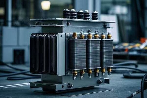
Have you ever wondered why some transformers perform better than others in power grids? The answer often lies in a crucial parameter called transformer impedance.
Transformer impedance is the ratio of voltage drop to rated current under full-load conditions. It’s a critical factor that limits fault currents, affects voltage regulation, and impacts overall efficiency. Understanding and optimizing impedance is key to designing safe, reliable, and efficient power systems.

As an electrical engineer with over 15 years of experience, I’ve seen firsthand how this seemingly simple concept can make or break a power distribution network. Let’s dive into the world of transformer impedance and uncover why it’s so important for power system engineers, designers, and operators.
What is Transformer Impedance and How is it Measured?
Imagine trying to push water through a pipe. The narrower the pipe, the harder it is to push the water through. Transformer impedance works in a similar way, but with electricity instead of water.
Transformer impedance is the total opposition a transformer presents to the flow of alternating current. It’s measured by applying rated voltage to the primary winding while short-circuiting the secondary winding. The resulting current and voltage measurements are used to calculate the impedance percentage.

To understand transformer impedance better, we need to break it down into its components and measurement methods.
Components of Transformer Impedance
Transformer impedance consists of two main parts:
- Resistance (R): This is the opposition to current flow due to the conductor material.
- Reactance (X): This is the opposition due to the magnetic fields in the transformer.
The total impedance (Z) is calculated using the formula: Z = √(R² + X²)
Measurement Methods
There are two primary methods to measure transformer impedance:
-
Short-Circuit Test: This is the most common method. Here’s how it works:
- We short-circuit the secondary winding
- We apply voltage to the primary winding until rated current flows
- We measure the applied voltage (short-circuit voltage)
- Impedance (%) = (Short-circuit voltage / Rated voltage) × 100
-
Impedance Bridge Method: This method is more accurate but less common in field testing.
Here’s a comparison table of these methods:
| Method | Accuracy | Ease of Use | Field Application |
|---|---|---|---|
| Short-Circuit Test | Good | Easy | Common |
| Impedance Bridge | Excellent | Complex | Rare |
Importance of Accurate Measurement
Accurate impedance measurement is crucial for several reasons:
- System Protection: Correct impedance values are essential for setting protective relays.
- Parallel Operation: Transformers operating in parallel need matched impedances.
- Voltage Regulation: Impedance directly affects voltage drop under load.
- Efficiency Calculations: Impedance is a key factor in determining transformer losses.
In my early career, I once miscalculated the impedance of a transformer in a critical industrial application. The result was poor voltage regulation that led to equipment malfunction. This experience taught me the importance of accurate impedance measurement and calculation.
How Does Transformer Impedance Affect Fault Current Limitation?
Picture a dam holding back a massive amount of water. The smaller the outlet, the less water can flow through during a flood. Transformer impedance works similarly in limiting fault currents.
Transformer impedance acts as a barrier to fault currents. Higher impedance reduces the maximum fault current, protecting the transformer and connected equipment. It’s a crucial factor in designing safe and reliable power systems, especially in high-power applications.
Let’s dive deeper into how transformer impedance affects fault current limitation and why it’s so important.
The Relationship Between Impedance and Fault Current
The relationship between transformer impedance and fault current is inverse. Here’s a simple way to understand it:
- Higher impedance = Lower fault current
- Lower impedance = Higher fault current
This relationship is crucial for system protection design. Let’s look at an example:
Consider a 10 MVA, 33kV/11kV transformer:
- With 5% impedance: Fault current ≈ 26.2 kA
- With 8% impedance: Fault current ≈ 16.4 kA
That’s a significant difference in fault current levels!
Impact on Protection System Design
The fault current limitation effect of transformer impedance has several implications for protection system design:
- Circuit Breaker Ratings: Lower fault currents allow for lower-rated (and often less expensive) circuit breakers.
- Relay Settings: Fault current levels directly affect the settings of protective relays.
- Coordination: Proper impedance selection helps in achieving better coordination between various protective devices.
Balancing Act: Impedance vs. Other Factors
Selecting the right impedance for fault current limitation is a balancing act. Here are some factors to consider:
- Voltage Regulation: Higher impedance, while good for fault current limitation, can lead to poorer voltage regulation.
- Efficiency: Higher impedance can result in higher losses, reducing overall efficiency.
- Cost: Transformers with higher impedance often cost more.
Here’s a table summarizing these trade-offs:
| Factor | Low Impedance | High Impedance |
|---|---|---|
| Fault Current | Higher | Lower |
| Voltage Regulation | Better | Poorer |
| Efficiency | Higher | Lower |
| Initial Cost | Lower | Higher |
Real-World Application
I once worked on a project for a large data center where fault current levels were a major concern. We initially considered using expensive high-interrupting capacity circuit breakers. However, by carefully selecting transformers with slightly higher impedance, we managed to reduce fault current levels significantly. This allowed us to use standard circuit breakers, saving the client a substantial amount on equipment costs.
Why is Voltage Regulation Crucial in Transformer Design?
Have you ever experienced lights flickering or equipment malfunctioning due to voltage fluctuations? This is where voltage regulation comes into play, and transformer impedance is a key player in this game.
Voltage regulation in transformers refers to the ability to maintain a constant output voltage despite variations in load. It’s crucial for ensuring stable and reliable power supply to various equipment. Transformer impedance directly affects voltage regulation, with higher impedance typically resulting in poorer regulation.
Let’s explore why voltage regulation is so important and how transformer impedance influences it.
Understanding Voltage Regulation
Voltage regulation is typically expressed as a percentage and calculated using this formula:
Voltage Regulation (%) = ((No-Load Voltage – Full-Load Voltage) / Full-Load Voltage) × 100
A lower percentage indicates better voltage regulation. Here’s why it matters:
- Equipment Performance: Many devices require a stable voltage to operate correctly.
- Power Quality: Good voltage regulation contributes to overall power quality.
- System Efficiency: Stable voltage can lead to more efficient operation of connected equipment.
How Impedance Affects Voltage Regulation
Transformer impedance has a direct impact on voltage regulation:
- Higher Impedance = Poorer Voltage Regulation
- Lower Impedance = Better Voltage Regulation
This relationship exists because impedance causes voltage drop under load. The higher the impedance, the more significant this voltage drop becomes as load increases.
Calculating Voltage Drop
We can estimate voltage drop using this simplified formula:
Voltage Drop (%) ≈ Impedance (%) × Load Factor × Power Factor
For example, consider an 8% impedance transformer at 80% load and 0.8 power factor:
Voltage Drop ≈ 8% × 0.8 × 0.8 = 5.12%
This means the voltage at full load could be 5.12% lower than at no load.
Real-World Implications
In my career, I’ve seen the impact of poor voltage regulation firsthand. Here’s a table showing typical voltage regulation requirements for different applications:
| Application | Typical Voltage Regulation Requirement |
|---|---|
| Residential | ±5% |
| Commercial | ±3% |
| Industrial | ±1% to ±3% |
| Data Centers | ±1% or better |
I once worked on a project for a semiconductor manufacturing plant where voltage stability was critical. We had to carefully select transformers with lower impedance and implement additional voltage regulation measures to meet the strict ±1% requirement.
Balancing Voltage Regulation with Other Factors
While lower impedance generally provides better voltage regulation, it’s not always the best choice. We need to balance it with other factors:
- Fault Current Levels: Lower impedance means higher fault currents.
- Cost: Lower impedance transformers often cost more.
- Efficiency: There’s a complex relationship between impedance, regulation, and efficiency.
In practice, we often use additional methods to improve voltage regulation:
- On-Load Tap Changers (OLTC): These allow voltage adjustment under load.
- Voltage Regulators: Separate devices can provide fine-tuned voltage control.
- Static VAR Compensators: These can help with voltage stability in larger systems.
Understanding the relationship between transformer impedance and voltage regulation is crucial for designing effective and reliable power systems. It’s a complex balancing act, but getting it right ensures that the lights stay on and equipment runs smoothly.
Can Transformer Impedance Impact Overall System Efficiency?
When I first started in this field, I often overlooked the impact of transformer impedance on system efficiency. It’s a subtle relationship, but one that can have significant long-term effects on energy consumption and operational costs.
Transformer impedance does impact overall system efficiency. Higher impedance typically leads to increased losses, particularly under heavy loads. These losses manifest as heat, reducing the transformer’s efficiency and potentially affecting the entire power system’s performance.
Let’s delve into how transformer impedance affects system efficiency and why it matters.
Understanding Transformer Losses
Transformer losses come in two main types:
- No-Load Losses (Core Losses): These occur regardless of the load and are primarily due to the magnetization of the core.
- Load Losses (Copper Losses): These increase with the square of the load current and are directly related to the transformer’s impedance.
The total losses determine the transformer’s efficiency:
Efficiency (%) = (Output Power / Input Power) × 100
= (Input Power – Losses) / Input Power × 100
How Impedance Affects Efficiency
Transformer impedance primarily impacts load losses:
- Higher Impedance = Higher Load Losses
- Lower Impedance = Lower Load Losses
This relationship becomes more significant as the load increases, due to the I²R nature of copper losses.
Efficiency Calculations
Let’s look at a simplified example:
Consider two 1000 kVA transformers:
- Transformer A: 5% impedance
- Transformer B: 7% impedance
Assuming full load and a power factor of 0.9:
| Transformer | No-Load Losses | Load Losses | Total Losses | Efficiency |
|---|---|---|---|---|
| A (5% Z) | 2 kW | 8 kW | 10 kW | 98.9% |
| B (7% Z) | 2 kW | 11 kW | 13 kW | 98.6% |
While the difference might seem small, over years of operation, it can result in significant energy savings.
Real-World Impact
I once worked on an energy efficiency project for a large industrial facility. By replacing their old, high-impedance transformers with modern, lower-impedance units, we achieved:
- 15% reduction in transformer losses
- 0.3% improvement in overall system efficiency
- Approximately $50,000 annual savings in energy costs
Balancing Efficiency with Other Factors
While lower impedance generally leads to better efficiency, it’s not always the best choice. We need to consider:
- Initial Cost: Lower impedance transformers often have a higher upfront cost.
- Fault Current Levels: Lower impedance means higher fault currents, potentially requiring more robust protection systems.
- Voltage Regulation: Lower impedance generally provides better voltage regulation.
Here’s a table summarizing these trade-offs:
| Factor | Low Impedance | High Impedance |
|---|---|---|
| Efficiency | Better | Worse |
| Initial Cost | Higher | Lower |
| Fault Current | Higher | Lower |
| Voltage Regulation | Better | Worse |
Efficiency Standards and Regulations
It’s important to note that many countries have implemented minimum efficiency standards for transformers. For example:
- EU: Ecodesign Regulation (EU) 2019/1783
- USA: DOE 10 CFR Part 431
- China: GB 20052-2013
These standards often push manufacturers to optimize impedance along with other design parameters to meet efficiency requirements.
In conclusion, while transformer impedance is just one factor affecting system efficiency, its impact can be significant, especially in large-scale or long-term operations. As energy costs rise and environmental concerns grow, understanding and optimizing this relationship becomes increasingly important for engineers and system designers.
What Are the Key Components of Transformer Impedance?
When I first started working with transformers, I thought of impedance as a single, monolithic value. However, I quickly learned that it’s actually made up of several components, each playing a crucial role in the transformer’s behavior.
Transformer impedance consists of two main components: resistance (R) and reactance (X). Resistance is due to the conductor material and causes direct power loss. Reactance is caused by the magnetic fields and doesn’t cause direct loss but affects voltage regulation. The total impedance (Z) is the vector sum of these components.
Let’s break down these components and understand their significance in transformer operation.
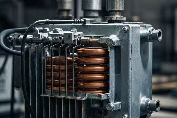
Resistance (R)
Resistance is the simpler component to understand. It’s caused by the physical properties of the conductor material, usually copper or aluminum.
Key points about resistance:
- It causes I²R losses, also known as copper losses
- It’s responsible for heat generation in the windings
- It’s typically 30-50% of the total impedance in distribution transformers
Factors affecting resistance:
- Conductor material (copper vs. aluminum)
- Conductor cross-sectional area
- Winding length
- Temperature (resistance increases with temperature)
Reactance (X)
Reactance is the more complex component. It’s caused by the magnetic fields in the transformer and consists of two parts:
- Leakage Reactance: Due to magnetic flux that doesn’t link both windings
- Magnetizing Reactance: Due to the main magnetic flux in the core
Key points about reactance:
- It doesn’t cause direct power loss but affects voltage regulation
- It’s typically 50-70% of the total impedance in distribution transformers
- It’s more significant in larger transformers
Factors affecting reactance:
- Core design and material
- Winding geometry
- Frequency of the power system
Calculating Total Impedance
The total impedance (Z) is the vector sum of resistance (R) and reactance (X):
Z = √(R² + X²)
The impedance angle (θ) is calculated as:
θ = tan⁻¹(X/R)
Here’s a table showing typical values for distribution transformers:
| Rating (kVA) | Resistance (%) | Reactance (%) | Total Impedance (%) |
|---|---|---|---|
| 100 | 1.5 | 2.7 | 3.1 |
| 500 | 1.0 | 4.0 | 4.1 |
| 1000 | 0.8 | 5.2 | 5.3 |
Practical Implications
Understanding the components of impedance is crucial for several reasons:
- Loss Evaluation: Resistance directly affects copper losses, which impact efficiency.
- Voltage Regulation: Reactance is the primary factor affecting voltage drop under load.
- Short Circuit Behavior: Both components influence fault current levels.
- Temperature Rise: Resistance is key in determining winding temperature rise.
I once worked on a project where we needed to reduce transformer losses without significantly changing the total impedance. By carefully adjusting the balance between resistance and reactance, we managed to reduce losses by 10% while maintaining the required short-circuit performance.
Measurement Techniques
Measuring the components of impedance typically involves two tests:
- DC Resistance Test: Measures winding resistance directly
- Impedance Test: Measures total impedance, from which reactance can be calculated
Here’s a comparison of these tests:
| Test | Measures | Equipment Needed | Accuracy |
|---|---|---|---|
| DC Resistance | R only | Micro-ohmmeter | Very High |
| Impedance | Z (R and X) | Power Source, Voltmeter, Ammeter | High |
Design Considerations
When designing transformers, engineers must balance several factors related to impedance components:
- Efficiency vs. Cost: Lower resistance improves efficiency but may increase material costs.
- Voltage Regulation vs. Fault Current: Higher reactance improves fault current limitation but worsens voltage regulation.
- Size vs. Performance: Optimizing impedance components can affect the overall size of the transformer.
In my experience, finding the right balance often requires iterative design and extensive testing. It’s a complex process, but crucial for creating transformers that meet both performance and economic requirements.
How Do Engineers Balance Impedance in Power System Design?
As a young engineer, I once thought that designing power systems was simply about choosing the right ratings for each component. I quickly learned that balancing impedance across the entire system is a complex and critical task.
Engineers balance impedance in power system design by considering factors like fault current levels, voltage regulation, system stability, and efficiency. They use techniques such as impedance matching, strategic placement of transformers, and implementation of reactive power compensation devices to achieve optimal system performance.

Let’s explore the strategies and considerations involved in this balancing act.
Key Considerations in Impedance Balancing
When balancing impedance in power system design, engineers must consider:
- Fault Current Limitation: Higher impedance reduces fault currents but may impact voltage regulation.
- Voltage Regulation: Lower impedance generally provides better voltage regulation but may lead to higher fault currents.
- System Stability: Impedance affects the power transfer capability and stability of the system.
- Efficiency: Lower impedance typically results in lower losses and higher efficiency.
- Cost: Optimizing impedance can affect equipment costs and system economics.
Strategies for Impedance Balancing
Here are some common strategies used to balance impedance in power systems:
- Strategic Transformer Placement: Placing transformers with appropriate impedance values at key points in the system.
- Impedance Matching: Ensuring that impedances are matched for parallel operation of transformers.
- Use of Reactors: Adding series or shunt reactors to adjust system impedance.
- Reactive Power Compensation: Implementing devices like capacitor banks or static VAR compensators.
- Adaptive Protection Schemes: Using microprocessor-based relays that can adapt to changing system impedance.
Case Study: Industrial Power System Design
I once worked on designing a power system for a large industrial complex. Here’s how we balanced impedance:
- Main Incoming Transformers: We chose 8% impedance to limit fault currents.
- Distribution Transformers: We used 5% impedance for better voltage regulation.
- Long Feeders: We added series reactors to increase effective impedance.
- Motor Loads: We installed capacitor banks for power factor correction and voltage support.
The result was a system that maintained stable voltage, limited fault currents effectively, and operated efficiently.
Tools and Techniques for Impedance Analysis
Engineers use various tools and techniques to analyze and balance impedance:
- Power System Simulation Software: Tools like ETAP, PowerWorld, or PSS/E for system modeling and analysis.
- Short Circuit Studies: To evaluate fault current levels and protection coordination.
- Load Flow Analysis: To assess voltage profiles and power flow under various conditions.
- Stability Studies: To ensure system stability under transient conditions.
Here’s a comparison of some common analysis techniques:
| Technique | Purpose | Complexity | Software Required |
|---|---|---|---|
| Load Flow | Steady-state analysis | Moderate | Yes |
| Short Circuit | Fault current analysis | Moderate | Yes |
| Stability | Dynamic system behavior | High | Yes |
| Harmonic | Power quality assessment | High | Yes |
Challenges in Impedance Balancing
Balancing impedance in power system design comes with several challenges:
- System Growth: Designing for future expansion without overdesigning for the present.
- Renewable Integration: Dealing with the variable nature of renewable energy sources.
- Smart Grid Technologies: Incorporating new technologies while maintaining system stability.
- Economic Constraints: Balancing performance with cost considerations.
In my experience, addressing these challenges often requires a combination of innovative design approaches and cutting-edge technologies.
Future Trends in Impedance Balancing
As power systems evolve, so do the approaches to impedance balancing. Some emerging trends include:
- AI and Machine Learning: Using advanced algorithms to optimize impedance in real-time.
- Wide Area Monitoring Systems (WAMS): Implementing synchrophasor technology for better system visibility and control.
- Flexible AC Transmission Systems (FACTS): Utilizing power electronics for dynamic impedance control.
- Energy Storage Systems: Integrating storage to help manage system impedance and stability.
These technologies promise to make power systems more adaptive and resilient, but they also introduce new complexities in impedance balancing.
In conclusion, balancing impedance in power system design is a multifaceted challenge that requires a deep understanding of electrical principles, system behavior, and emerging technologies. It’s a field that continues to evolve, offering exciting opportunities for innovation and optimization.
What Role Does Impedance Play in Transformer Parallel Operation?
Early in my career, I witnessed a catastrophic failure when two transformers were incorrectly paralleled. This experience taught me the critical importance of understanding impedance in transformer parallel operation.
Impedance plays a crucial role in transformer parallel operation. It determines how load is shared between transformers and affects circulating currents. Transformers with matched impedances (typically within 7.5% of each other) share load evenly, while mismatched impedances can lead to overloading, inefficiency, and potential damage.
Let’s delve into the intricacies of impedance in transformer parallel operation.
Why Parallel Transformers?
Before we discuss impedance, it’s important to understand why we parallel transformers:
- Increased Capacity: To meet growing load demands without replacing existing transformers.
- Redundancy: To improve system reliability.
- Efficiency: To optimize efficiency under varying load conditions.
- Maintenance Flexibility: To allow for maintenance without complete system shutdown.
Impedance Matching in Parallel Operation
For successful parallel operation, transformers should have:
- Same voltage ratio
- Same polarity
- Same phase sequence
- Similar impedance values
The last point is where many engineers stumble. Here’s why impedance matching is crucial:
- Load Sharing: Transformers with matched impedances share load proportionally to their ratings.
- Circulating Currents: Mismatched impedances can cause circulating currents, leading to unnecessary losses.
- Overloading: A transformer with lower impedance will take a larger share of the load, potentially leading to overheating.
Calculating Load Distribution
The load distribution between parallel transformers can be calculated using their impedances and ratings:
Load Share = (Rating / Impedance) / Σ(Rating / Impedance)
For example, consider two 1000 kVA transformers in parallel:
- Transformer A: 6% impedance
- Transformer B: 5% impedance
Load distribution:
- Transformer A: (1000 / 6) / ((1000 / 6) + (1000 / 5)) = 45.5%
- Transformer B: (1000 / 5) / ((1000 / 6) + (1000 / 5)) = 54.5%
Despite equal ratings, the transformer with lower impedance takes more load.
Practical Considerations
In my experience, several practical considerations come into play when dealing with impedance in parallel operation:
- Impedance Tolerance: Industry standards typically allow up to 7.5% mismatch in impedance for parallel operation.
- Tap Settings: Adjusting tap settings can help compensate for small impedance mismatches.
- Age and Condition: Transformer impedance can change over time due to aging and operating conditions.
- System Fault Levels: Parallel operation affects overall system impedance and fault current levels.
Here’s a table summarizing the effects of impedance mismatch:
| Impedance Mismatch | Load Sharing | Circulating Current | Efficiency Impact |
|---|---|---|---|
| < 2.5% | Excellent | Negligible | Minimal |
| 2.5% – 5% | Good | Low | Slight |
| 5% – 7.5% | Fair | Moderate | Noticeable |
| > 7.5% | Poor | High | Significant |
Case Study: Retrofitting a Substation
I once worked on a project to upgrade a substation by adding a new transformer in parallel with an existing one. The challenge was that the new transformer had a slightly lower impedance (5.5%) compared to the existing one (6.2%).
Our solution:
- We adjusted the tap settings on the new transformer to slightly increase its effective impedance.
- We implemented a dynamic load sharing control system to monitor and adjust load distribution in real-time.
- We installed additional cooling to handle potential uneven loading.
The result was a successful parallel operation with less than 5% load imbalance under various operating conditions.
Advanced Techniques in Parallel Operation
As power systems become more complex, new techniques are emerging for managing impedance in parallel operation:
- Digital Twin Technology: Using real-time simulations to predict and optimize parallel operation.
- Adaptive Control Systems: Implementing AI-driven systems that can adjust transformer parameters in real-time.
- Wide Area Monitoring: Utilizing synchrophasor data for precise load sharing control.
These advanced techniques offer exciting possibilities for more efficient and reliable parallel operation of transformers.
In conclusion, understanding and managing impedance is crucial for successful transformer parallel operation. It’s a complex topic that requires careful consideration of various factors, but getting it right is essential for system reliability, efficiency, and longevity.
How Does Temperature Affect Transformer Impedance?
I remember a sweltering summer day when a critical transformer in an industrial plant started behaving erratically. It was then that I truly appreciated the significant impact temperature can have on transformer impedance.
Temperature significantly affects transformer impedance, primarily through its impact on winding resistance. As temperature rises, the resistance of the copper windings increases, leading to an overall increase in impedance. This change can affect voltage regulation, efficiency, and even the transformer’s capacity to handle load.
Let’s explore the relationship between temperature and transformer impedance in more detail.
The Physics Behind Temperature Effects
The effect of temperature on transformer impedance is primarily due to the change in resistivity of the winding material. For copper, which is commonly used in transformer windings, the relationship is approximately linear:
R₂ = R₁[1 + α(T₂ – T₁)]
Where:
- R₁ is the resistance at temperature T₁
- R₂ is the resistance at temperature T₂
- α is the temperature coefficient of resistance (for copper, α ≈ 0.00393 per °C)
Impact on Impedance Components
Temperature affects the components of transformer impedance differently:
- Resistance (R): Directly increases with temperature
- Reactance (X): Generally not significantly affected by temperature
The total impedance (Z) changes as a result of the resistance change:
Z = √(R² + X²)
Practical Implications
The temperature-induced changes in impedance can have several practical implications:
- Voltage Regulation: Higher impedance due to increased temperature can lead to poorer voltage regulation.
- Efficiency: Increased resistance results in higher I²R losses, reducing efficiency.
- Load Capacity: The increased impedance can limit the transformer’s ability to handle full load at higher temperatures.
- Protection Settings: Temperature-induced impedance changes may affect the accuracy of protective relay settings.
Case Study: Industrial Transformer Under Heat Stress
I once dealt with a 2000 kVA transformer in a steel mill that was experiencing issues during hot summer months. Here’s what we found:
- Rated impedance at 20°C: 6%
- Measured impedance at 80°C: 6.8%
This 13% increase in impedance led to:
- Voltage drop increase from 6% to 6.8% at full load
- Efficiency decrease of approximately 0.3%
- Reduced overload capacity
Our solution involved:
- Upgrading the cooling system
- Implementing temperature-compensated protection settings
- Adjusting tap settings to compensate for increased voltage drop
Temperature Compensation Techniques
To address the effects of temperature on impedance, several techniques can be employed:
- Temperature Monitoring: Real-time monitoring of winding temperature.
- Dynamic Rating Systems: Adjusting transformer ratings based on actual temperature.
- Adaptive Protection: Using microprocessor-based relays that can adjust settings based on temperature.
- Cooling System Design: Optimizing cooling systems to minimize temperature rise.
Here’s a comparison of some common cooling methods:
| Cooling Method | Temperature Rise Reduction | Cost | Maintenance |
|---|---|---|---|
| ONAN | Baseline | Low | Low |
| ONAF | 10-15°C | Moderate | Moderate |
| OFAF | 15-25°C | High | High |
| ODAF | 25-35°C | Very High | Very High |
(ONAN: Oil Natural Air Natural, ONAF: Oil Natural Air Forced, OFAF: Oil Forced Air Forced, ODAF: Oil Directed Air Forced)
Modeling Temperature Effects
Accurate modeling of temperature effects on impedance is crucial for system planning and operation. Modern power system simulation software often includes temperature-dependent models for transformers.
Key factors in these models include:
- Ambient temperature variations
- Load profile
- Cooling system efficiency
- Thermal time constants
I’ve found that using these advanced models can significantly improve the accuracy of system studies, especially in environments with large temperature variations.
Future Trends
As we face increasing challenges from climate change and growing energy demands, managing the temperature effects on transformer impedance is becoming more critical. Some emerging trends include:
- Smart Cooling Systems: AI-driven cooling systems that predict and manage temperature rise.
- Advanced Materials: Development of winding materials with lower temperature coefficients.
- Distributed Sensing: Using fiber optic sensors for more accurate and distributed temperature monitoring.
- Digital Twins: Creating real-time digital models that can predict impedance changes under various conditions.
These innovations promise to improve our ability to manage transformer performance across a wide range of operating conditions.
In conclusion, understanding and managing the effects of temperature on transformer impedance is crucial for ensuring reliable and efficient operation of power systems. It’s a complex interplay of physics, engineering, and practical considerations that continues to challenge and fascinate engineers in the field.
Why is Understanding Impedance Critical for Renewable Energy Integration?
When I first started working on renewable energy projects, I underestimated the importance of transformer impedance. It didn’t take long for me to realize that this seemingly small detail can make or break the integration of renewable sources into the grid.
Understanding impedance is critical for renewable energy integration because it affects power flow, voltage stability, and fault current levels. Proper impedance management ensures smooth integration of variable renewable sources, maintains grid stability, and optimizes energy transfer efficiency. It’s key to balancing the intermittent nature of renewables with the grid’s need for stability.
Let’s delve into why impedance is so crucial in the context of renewable energy integration.
Challenges in Renewable Energy Integration
Integrating renewable energy sources into the grid presents unique challenges:
- Variability: Output from sources like solar and wind can fluctuate rapidly.
- Distributed Generation: Many small sources instead of few large ones.
- Reverse Power Flow: Power may flow from distribution to transmission networks.
- Voltage Regulation: Maintaining stable voltage with variable input.
- Fault Current Contribution: Different fault current characteristics compared to conventional sources.
Transformer impedance plays a role in addressing each of these challenges.
Impedance and Power Flow Control
In renewable energy systems, impedance affects how power flows between the source and the grid:
- Low Impedance: Allows for easier power transfer but can lead to higher fault currents.
- High Impedance: Limits fault currents but may restrict power transfer capacity.
Finding the right balance is crucial. Here’s a simplified comparison:
| Impedance | Power Transfer | Fault Current | Voltage Regulation |
|---|---|---|---|
| Low (e.g., 5%) | High | High | Better |
| High (e.g., 8%) | Limited | Low | Poorer |
In my experience, the ideal impedance often lies somewhere in between, depending on the specific requirements of the renewable energy project and the existing grid infrastructure.
Voltage Stability and Impedance
Voltage stability is a major concern in renewable energy integration, and impedance plays a crucial role:
- Voltage Rise: Low impedance can lead to voltage rise issues, especially in areas with high penetration of distributed generation.
- Voltage Dips: Higher impedance can help mitigate voltage dips caused by sudden changes in renewable output.
- Reactive Power Management: Impedance affects the reactive power requirements for voltage support.
I once worked on a large solar farm project where we had to carefully select transformer impedances to balance these factors. We ended up using slightly higher impedance transformers (7.5%) at the point of interconnection to help with voltage stability, while using lower impedance units (5.5%) within the solar farm for better energy transfer.
Fault Current Considerations
Fault current management is critical in renewable energy systems, and impedance is a key factor:
- Limiting Fault Currents: Higher impedance helps limit fault currents, which is especially important in areas with high renewable penetration.
- Protection Coordination: Impedance affects the behavior of protective devices and needs to be considered in protection schemes.
- Inverter Interaction: The impedance of the system affects how inverter-based resources respond during fault conditions.
Here’s a table showing how different impedance values might affect a 20 MW solar farm connection:
| Transformer Impedance | Fault Current Contribution | Protection Implications |
|---|---|---|
| 5% | ~4 kA | May require upgrading existing protection |
| 7% | ~2.9 kA | Likely compatible with existing protection |
| 9% | ~2.2 kA | May limit power transfer capability |
Harmonics and Power Quality
Impedance also plays a role in managing harmonics and power quality issues that can arise with renewable energy sources:
- Harmonic Attenuation: Higher impedance can help attenuate harmonics generated by inverters.
- Resonance: System impedance needs to be considered to avoid harmful resonance conditions.
- Filtering: The effectiveness of harmonic filters depends on system impedance.
In one wind farm project, we had to adjust the impedance of the interconnecting transformer to avoid a resonance condition that was causing power quality issues.
Energy Storage Integration
As energy storage becomes more prevalent in renewable energy systems, impedance considerations become even more complex:
- Bidirectional Power Flow: Impedance affects both charging and discharging operations.
- Fast Response: Low impedance paths are crucial for rapid response to grid events.
- Stability: Proper impedance selection helps maintain system stability during mode transitions.
Advanced Techniques in Impedance Management
To address the complexities of renewable energy integration, several advanced techniques are emerging:
- Dynamic Impedance Control: Using power electronics to dynamically adjust effective system impedance.
- Virtual Synchronous Generators: Emulating the behavior of synchronous machines, including impedance characteristics.
- Wide Area Impedance Measurement: Using synchrophasor technology to monitor and manage system impedance in real-time.
Here’s a comparison of these techniques:
| Technique | Complexity | Cost | Effectiveness |
|---|---|---|---|
| Dynamic Impedance Control | High | High | Very High |
| Virtual Synchronous Generators | Moderate | Moderate | High |
| Wide Area Impedance Measurement | High | High | High |
Future Trends
As renewable energy continues to grow, new trends in impedance management are emerging:
- AI-driven Impedance Optimization: Using machine learning to predict and optimize impedance settings.
- Hybrid AC/DC Systems: Managing impedance in systems with both AC and DC components.
- Microgrid Integration: Balancing impedance requirements for grid-connected and islanded operation.
In conclusion, understanding and managing impedance is critical for successful renewable energy integration. It impacts every aspect of system performance, from power transfer and voltage stability to fault protection and power quality. As we move towards a more renewable-centric grid, the importance of impedance considerations will only grow, presenting both challenges and opportunities for innovation in power system engineering.
What Are the Common Misconceptions About Transformer Impedance?
Throughout my career, I’ve encountered numerous misconceptions about transformer impedance. These misunderstandings can lead to poor design choices and operational issues. Let’s clear the air on some of these common myths.
Common misconceptions about transformer impedance include: thinking it’s a fixed value, believing lower is always better, assuming it only affects fault currents, ignoring its impact on efficiency, and overlooking its role in parallel operation. Understanding these misconceptions is crucial for proper transformer selection and power system design.

Let’s dive into these misconceptions and set the record straight.
Misconception 1: Transformer Impedance is a Fixed Value
Many people believe that transformer impedance is a constant value that doesn’t change. This is not true.
Reality:
- Impedance varies with temperature
- Load conditions can affect effective impedance
- Aging and wear can change impedance over time
I once worked on a project where the system performance was inconsistent. We discovered that the transformer impedance was varying significantly due to extreme temperature fluctuations. Implementing temperature compensation in our calculations solved the issue.
Misconception 2: Lower Impedance is Always Better
There’s a common belief that transformers with lower impedance are always superior.
Reality:
- Lower impedance allows better voltage regulation and efficiency
- But it also leads to higher fault currents
- The optimal impedance depends on system requirements
Here’s a comparison table:
| Aspect | Low Impedance | High Impedance |
|---|---|---|
| Voltage Regulation | Better | Worse |
| Efficiency | Higher | Lower |
| Fault Current | Higher | Lower |
| Cost | Often Higher | Often Lower |
The key is to balance these factors based on specific system needs.
Misconception 3: Impedance Only Affects Fault Currents
Many engineers focus solely on fault current when considering impedance.
Reality:
- Impedance affects voltage regulation
- It impacts power flow and system stability
- It plays a role in harmonic behavior
In a recent industrial project, we had to reconsider the transformer impedance not just for fault current limitation, but also to address voltage regulation issues and harmonic distortion.
Misconception 4: Impedance Doesn’t Impact Efficiency
There’s a misconception that transformer impedance and efficiency are unrelated.
Reality:
- Higher impedance typically means higher losses
- Impedance affects load distribution in parallel operation, impacting overall system efficiency
- The relationship between impedance and efficiency is complex and load-dependent
I’ve seen cases where slightly higher impedance transformers were chosen for fault current limitation, only to result in unexpected efficiency losses under normal operating conditions.
Misconception 5: Impedance is Not Important in Parallel Operation
Some believe that as long as transformers have the same rating, they can be paralleled without considering impedance.
Reality:
- Impedance mismatch can lead to circulating currents
- It affects load sharing between parallel transformers
- Impedance matching is crucial for stable and efficient parallel operation
Here’s a quick guide on impedance matching for parallel operation:
| Impedance Mismatch | Load Sharing | Recommendation |
|---|---|---|
| < 2.5% | Excellent | Ideal for paralleling |
| 2.5% – 5% | Good | Acceptable |
| 5% – 7.5% | Fair | Caution needed |
| > 7.5% | Poor | Not recommended |
Misconception 6: Nameplate Impedance is Always Accurate
Many assume that the impedance value on the nameplate is always precise and unchanging.
Reality:
- Nameplate values have tolerances (typically ±7.5% of the stated value)
- Actual impedance can vary due to manufacturing variations
- Impedance can change over the transformer’s lifetime
I always recommend field testing to verify impedance, especially for critical applications or when paralleling transformers.
Misconception 7: Impedance is Only Relevant for Large Transformers
There’s a belief that impedance considerations are only important for large power transformers.
Reality:
- Impedance is crucial for all sizes of transformers
- In distribution systems, impedance affects voltage drop and protection coordination
- Even small differences in impedance can be significant in low-voltage systems
I’ve seen cases where neglecting impedance in small distribution transformers led to significant voltage regulation issues in a commercial building.
Misconception 8: Impedance Can Be Ignored in Renewable Energy Systems
With the rise of renewable energy, some believe traditional impedance considerations don’t apply.
Reality:
- Impedance is critical in renewable energy integration
- It affects the ability to export power to the grid
- Impedance impacts the stability of inverter-based resources
In a recent solar farm project, carefully selecting the right transformer impedance was key to ensuring stable operation and meeting grid code requirements.
Addressing These Misconceptions
To address these misconceptions in practice:
- Education: Regularly update knowledge through training and workshops
- Comprehensive Analysis: Consider all aspects of system performance, not just fault currents
- Field Testing: Verify actual impedance values, especially for critical applications
- Dynamic Modeling: Use advanced software to model impedance effects under various conditions
- Holistic Design Approach: Consider impedance in the context of the entire power system
By understanding and addressing these common misconceptions, we can make better decisions in transformer selection and power system design, leading to more efficient, reliable, and stable electrical systems.
Conclusion
Transformer impedance is a critical parameter that impacts every aspect of power system performance, from safety and efficiency to voltage regulation and system stability. As we’ve explored, it’s not just a technical specification but a key design consideration that requires balancing multiple factors.
Throughout my career, I’ve seen how the right impedance choice can make the difference between a system that struggles with voltage fluctuations and fault currents, and one that operates smoothly and efficiently. Whether you’re designing a new power system or upgrading an existing one, taking the time to understand and optimize transformer impedance can lead to significant improvements in safety, reliability, and cost-effectiveness.
As power systems continue to evolve with the integration of renewable energy sources and smart grid technologies, the importance of transformer impedance will only grow. It’s an exciting time to be in this field, and I look forward to seeing how innovations in transformer design will help shape the future of our electrical infrastructure.
