Understanding Distribution Transformer Diagram: A Comprehensive Guide for Electrical Engineers?
Have you ever stared at a distribution transformer diagram and felt lost? You’re not alone. Many engineers struggle to decode these complex schematics.
Distribution transformer diagrams are essential tools for electrical engineers. They provide a visual representation of the transformer’s components, connections, and functionality. Understanding these diagrams is crucial for design, maintenance, and troubleshooting in power distribution systems.
I’ve spent years working with distribution transformer diagrams. I’ve seen how a clear understanding of these schematics can make or break a project. Let’s dive into the world of transformer diagrams and uncover their secrets.
Decoding the Components: Key Elements of a Distribution Transformer Diagram?
Have you ever wondered what all those symbols on a transformer diagram mean? It’s like learning a new language, but one that’s crucial for your work.
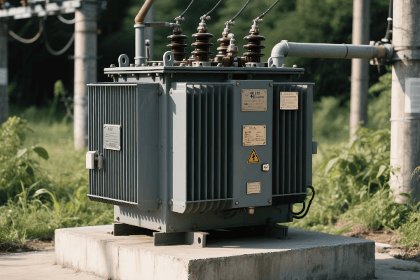
Distribution transformer diagrams consist of several key components, each represented by specific symbols. These include the core, windings, bushings, tap changers, and protective devices. Understanding these elements is fundamental to interpreting the diagram correctly.
In my early days as an engineer, I often felt overwhelmed by the complexity of these diagrams. But as I learned to identify each component, the bigger picture became clear. Here’s what you need to know:
Core and Windings
The heart of the transformer:
- Core: Usually represented by rectangular shapes.
- Primary Winding: Often shown on the left side.
- Secondary Winding: Typically on the right side.
I once worked on a project where misinterpreting the winding configuration led to a costly mistake. It taught me the importance of understanding these basic elements.
Bushings and Connections
How the transformer connects to the outside world:
| Component | Symbol | Function |
|---|---|---|
| High Voltage Bushing | Triangle or circle with H | Connects to high voltage line |
| Low Voltage Bushing | Triangle or circle with X | Connects to low voltage line |
| Neutral Bushing | Triangle or circle with N | Grounding connection |
Understanding these connections is crucial. In a recent installation, correctly identifying the bushing types ensured proper grounding and safety.
Tap Changers and Regulators
Adjusting voltage levels:
- On-Load Tap Changer (OLTC): Shown as a series of contacts.
- Off-Circuit Tap Changer: Similar to OLTC but with a different symbol.
- Voltage Regulator: Often represented as a variable resistor symbol.
I’ve seen engineers overlook tap changers in diagrams, leading to voltage regulation issues. Always pay attention to these components.
Protective Devices
Keeping the transformer safe:
- Buchholz Relay: Usually shown near the top of the tank.
- Pressure Relief Device: Often represented by a circle with an arrow.
- Temperature Indicators: Shown as thermometer symbols.
In a recent troubleshooting case, identifying a faulty Buchholz relay from the diagram helped us prevent a potential transformer failure.
Symbols and Notations: Mastering the Language of Transformer Schematics?
Do transformer diagrams sometimes look like a foreign language to you? You’re not alone. But mastering this language is key to your success as an electrical engineer.
Symbols and notations in transformer schematics form a standardized language for electrical engineers. They represent various components, connections, and functions of the transformer. Understanding these symbols is crucial for accurate interpretation and effective communication in the field.
When I first started working with transformer diagrams, I felt like I was deciphering hieroglyphics. But over time, I realized how powerful this visual language can be. Let’s break it down:
Basic Electrical Symbols
The building blocks of any transformer diagram:
- Lines: Represent conductors or connections.
- Zigzag Lines: Often used for windings.
- Circles: Can represent bushings or connection points.
I once caught a critical wiring error just by noticing an unusual line configuration in a diagram. It saved us from a potential equipment failure.
Transformer-Specific Symbols
Unique to transformer schematics:
| Symbol | Meaning |
|---|---|
| Rectangle with Lines | Transformer Core |
| Overlapping Circles | Windings |
| Arrow through Circle | Tap Changer |
| Lightning Bolt | Surge Arrester |
Understanding these symbols is crucial. In a recent project, quickly identifying a missing surge arrester symbol in the diagram prevented a costly oversight in lightning protection.
Polarity and Phase Markings
Indicating current flow and phase relationships:
- Dot Convention: Dots show winding polarity.
- H1, H2 (High Voltage) and X1, X2 (Low Voltage): Standard terminal markings.
- Phase Notations: A, B, C or R, Y, B for three-phase systems.
I’ve seen confusion arise from misinterpreted polarity markings. Always double-check these to ensure proper transformer connections.
Ratings and Specifications
Key information often included in diagrams:
- kVA Rating: Transformer capacity.
- Voltage Ratings: Primary and secondary voltages.
- Impedance: Usually expressed as a percentage.
During a system upgrade, correctly reading the impedance value from a diagram helped us avoid a potential mismatch in fault current calculations.
Practical Applications: Using Distribution Transformer Diagrams for Troubleshooting?
Ever faced a transformer issue and felt stuck? The solution might be right there in the diagram. But how do you use it effectively?
Distribution transformer diagrams are invaluable tools for troubleshooting. They provide a comprehensive view of the transformer’s structure and connections, allowing engineers to identify potential fault points, trace electrical paths, and plan diagnostic tests efficiently.

I’ve used transformer diagrams countless times to solve complex issues. Here’s how you can leverage them for effective troubleshooting:
Fault Isolation
Pinpointing problem areas:
- Trace Electrical Paths: Follow the lines to identify potential fault locations.
- Check Connection Points: Bushings and terminals are common fault areas.
- Examine Protection Devices: Look for tripped indicators in the diagram.
I once solved a mysterious power outage by tracing a fault to a rarely-used auxiliary connection shown in the diagram. It wasn’t even considered in the initial troubleshooting.
Test Point Identification
Planning your diagnostic approach:
| Test Type | Diagram Use |
|---|---|
| Insulation Resistance | Identify winding terminals |
| Turn Ratio | Locate primary and secondary connections |
| Winding Resistance | Find specific winding start and end points |
Using the diagram to plan tests saves time and improves accuracy. In a recent case, I quickly identified the correct test points for a complex partial discharge test, streamlining the entire process.
Comparative Analysis
Using the diagram as a reference:
- Compare As-Built to Design: Check for discrepancies.
- Historical Comparison: Look for changes over time.
- Benchmark Against Standards: Ensure compliance with industry norms.
I’ve caught several installation errors by comparing the actual transformer setup to the diagram. It’s a practice that has saved both time and resources.
Safety Planning
Ensuring safe troubleshooting:
- Identify Isolation Points: Locate disconnects and grounding points.
- Recognize High Voltage Areas: Plan safe access routes.
- Verify Protection Schemes: Understand built-in safety features.
Safety is paramount. I always use the diagram to brief my team on potential hazards before any hands-on work.
From Blueprint to Reality: Implementing Distribution Transformer Diagrams in System Design?
Ever wondered how a transformer goes from a drawing to a working part of the power grid? It’s a journey that starts with a diagram and ends with a crucial piece of infrastructure.
Implementing distribution transformer diagrams in system design involves translating schematic representations into physical installations. This process requires careful planning, precise execution, and thorough verification to ensure the transformer functions as intended within the larger power distribution system.
I’ve overseen many transformer installations, and the diagram is always our roadmap. Here’s how we bring these blueprints to life:
Design Verification
Ensuring the diagram meets system requirements:
- Load Analysis: Verify the transformer capacity matches the demand.
- Voltage Levels: Confirm primary and secondary voltages are correct.
- Protection Schemes: Check if all necessary protective devices are included.
I once caught a major design flaw during this stage. The diagram showed a transformer with insufficient capacity for future expansion plans. Catching this early saved a costly replacement down the line.
Component Selection
Choosing the right parts based on the diagram:
| Component | Selection Criteria |
|---|---|
| Core | Material and construction type |
| Windings | Conductor material and insulation class |
| Bushings | Voltage rating and current capacity |
| Tap Changers | Range and step size |
Selecting the right components is crucial. I remember a project where we had to custom-order bushings because the standard ones didn’t match the unique configuration in our diagram.
Physical Layout Planning
Translating 2D diagrams to 3D reality:
- Space Allocation: Ensure adequate room for all components.
- Accessibility: Plan for maintenance and testing access.
- Cooling Considerations: Arrange components for optimal heat dissipation.
I’ve learned to always consider the physical space. In one installation, we had to redesign the layout because the diagram didn’t account for the limited space in an urban substation.
Wiring and Connections
Bringing the diagram to life:
- Follow Connection Paths: Use the diagram as a wiring guide.
- Verify Polarities: Ensure winding connections match the diagram.
- Implement Grounding: Install ground connections as shown.
Attention to detail is key here. I once prevented a potential disaster by catching a reversed polarity connection that didn’t match the diagram.
Comparative Analysis: Exploring Various Types of Distribution Transformer Diagrams?
Did you know that not all transformer diagrams are created equal? Understanding the differences can give you a significant edge in your work.
Distribution transformer diagrams come in various types, each serving a specific purpose. These include single-line diagrams, schematic diagrams, winding diagrams, and connection diagrams. Each type offers unique insights into the transformer’s structure and function.
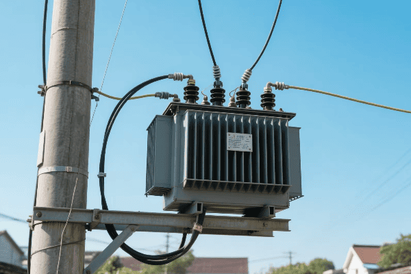
In my career, I’ve worked with all types of transformer diagrams. Each has its strengths, and knowing when to use which can make your job much easier. Let’s compare them:
Single-Line Diagrams
The big picture view:
- Purpose: Show overall system layout.
- Level of Detail: Low, focuses on major components.
- Best Used For: System planning and high-level understanding.
I often start with single-line diagrams when explaining system upgrades to non-technical stakeholders. They provide a clear, simplified view of how the transformer fits into the larger picture.
Schematic Diagrams
Detailed electrical representations:
| Feature | Description |
|---|---|
| Component Symbols | Shows all electrical parts |
| Connection Paths | Illustrates how components are linked |
| Electrical Values | Often includes ratings and specifications |
Schematic diagrams are my go-to for troubleshooting. Their detailed nature once helped me identify a subtle wiring issue that was causing intermittent faults.
Winding Diagrams
Focused on internal transformer structure:
- Coil Arrangements: Shows how windings are constructed.
- Turn Ratios: Illustrates voltage transformation details.
- Tap Positions: Indicates voltage adjustment points.
Understanding winding diagrams is crucial for maintenance. I’ve used them to guide rewinding processes and to diagnose internal faults that weren’t apparent from other diagram types.
Connection Diagrams
Emphasizing external connections:
- Terminal Layouts: Shows how to connect the transformer to the system.
- Phasing Information: Crucial for three-phase systems.
- Grounding Points: Indicates where and how to ground the transformer.
Connection diagrams are invaluable during installation. I always refer to them to ensure proper system integration and to avoid potentially dangerous misconnections.
Conclusion
Understanding distribution transformer diagrams is crucial for electrical engineers. From component identification to practical troubleshooting, these diagrams are essential tools for designing, maintaining, and optimizing power distribution systems.
Free CHBEB Transformer Catalog Download
Get the full range of CHBEB transformers in one catalog.
Includes oil-immersed, dry-type, pad-mounted, and custom solutions.
Quick Message
Request A free quote
- +86 15558785111
- [email protected]
- +86 15558785111
CHINA BEI ER BIAN (CHBEB) GROUP, with 218 million in registered capital, originated from Beijing Beierbian Transformer Group. Headquartered in Beijing for R&D, it operates major production bases in Nanjing and Yueqing, producing high-quality products.
No 3,RongJing East Road,BeiJing Economic Technological Development Area,BeiJing,China
No 7️Xiangfeng Road,Jiangning,NanJing,JiangSu,China
No.211, Wei 16 Road, Industrial Zone, Yueqing, Wenzhou, Zhejiang, China.
XiangYang Industrial Zone ,YueQing,WenZhou,ZheJiang,China
- [email protected]
- +86 13057780111
- +86 13057780111
- +86 15558785111
Copyright © Bei Er Bian Group


