Have you ever wondered about those cylindrical devices perched atop utility poles in your neighborhood? These unassuming units play a crucial role in delivering electricity to our homes and businesses. But what exactly are they, and how do they work?
A pole-mounted distribution transformer is an oil-filled electrical device installed on utility poles to step down medium-voltage electricity (typically 11kV or 22kV) to lower voltages (usually 230V or 400V) for end-user consumption. It consists of a core, windings, and an insulating oil-filled tank, along with external components like bushings, fuses, and lightning arresters. These transformers work on the principle of electromagnetic induction, efficiently converting voltage levels without direct electrical contact between primary and secondary circuits.

In this comprehensive guide, I’ll take you through the structure, working principle, and key components of pole distribution transformers. Whether you’re an engineer, project manager, or simply curious about the power infrastructure around you, understanding these devices will give you valuable insights into how electricity reaches our homes and businesses safely and efficiently.
What Is a Pole-Mounted Distribution Transformer?
Have you ever noticed those barrel-shaped devices attached to utility poles and wondered about their purpose? These are pole-mounted distribution transformers, but what exactly do they do, and why are they so important for our power distribution system?
A pole-mounted distribution transformer is a compact, oil-filled electrical device installed on utility poles to convert medium-voltage electricity from power lines (typically 6kV, 11kV, or 22kV) to lower voltages (usually 230V or 400V) suitable for residential and small commercial use. These transformers are crucial for efficient power distribution in rural areas, suburban regions, and areas with low population density. They serve as the final voltage step-down point before electricity reaches end-users, ensuring safe and usable power delivery.
Key Aspects of Pole-Mounted Distribution Transformers
Let’s break down the main features:
- Purpose and Function
- Physical Characteristics
- Voltage Ratings
- Applications
- Advantages and Limitations
Purpose and Function
The primary role in power distribution:
- Step down medium voltage to low voltage for end-user consumption
- Act as a crucial link between transmission lines and local distribution
- Provide electrical isolation between primary and secondary circuits
I recently visited a rural electrification project where pole-mounted transformers were being installed. It was fascinating to see how these compact devices could bring power from high-voltage lines directly to small clusters of homes and farms.
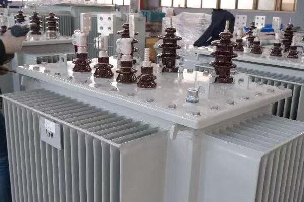
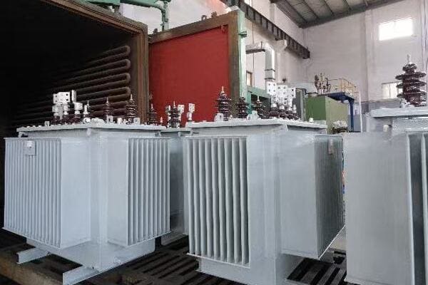
Physical Characteristics
Designed for outdoor installation:
- Cylindrical or rectangular tank filled with insulating oil
- Mounted on utility poles using specialized brackets
- Equipped with cooling fins for heat dissipation
- Typically weighing between 200 to 1000 kg, depending on capacity
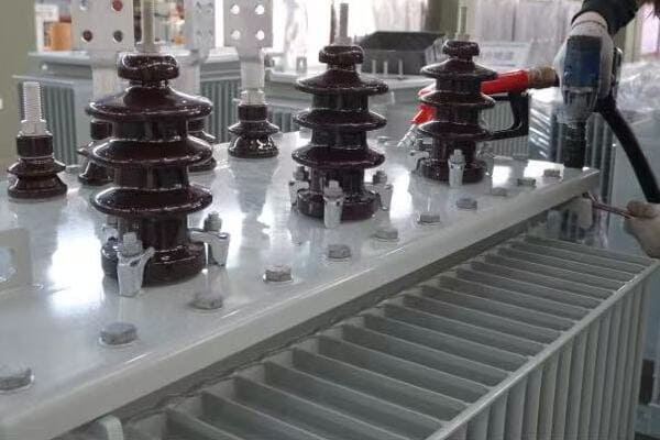
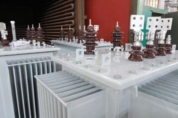
During a recent factory tour, I observed the manufacturing process of these transformers. The precision in assembly and the robust construction necessary for withstanding outdoor conditions were impressive.
Voltage Ratings
Adapting to various distribution systems:
- Primary (input) voltages: Commonly 6kV, 11kV, or 22kV
- Secondary (output) voltages: Typically 230V (single-phase) or 400V (three-phase)
- Capacity ranges from 5 kVA to 250 kVA for most pole-mounted units
Here’s a quick overview of common voltage ratings:
| Primary Voltage | Secondary Voltage | Typical Capacities |
|---|---|---|
| 6kV | 230V/400V | 25 – 100 kVA |
| 11kV | 230V/400V | 50 – 200 kVA |
| 22kV | 230V/400V | 100 – 250 kVA |
Applications
Versatile use in various settings:
- Rural electrification projects
- Suburban areas with overhead power lines
- Small commercial and industrial facilities
- Agricultural settings for irrigation and farm equipment
Advantages and Limitations
Understanding the pros and cons:
- Advantages: Cost-effective, easy to install and maintain, suitable for areas with low power density
- Limitations: Limited capacity, exposed to weather conditions, potential safety concerns in densely populated areas
Key points about pole-mounted distribution transformers:
- They are crucial for stepping down voltage in the final distribution stage
- Designed specifically for outdoor, pole-top installation
- Come in various voltage ratings to suit different distribution systems
- Widely used in rural and suburban power distribution
- Offer a balance of cost-effectiveness and practicality for certain applications
In my experience, understanding these basic aspects of pole-mounted transformers is crucial for effective power distribution planning. I recall a project in a developing rural area where the strategic placement of these transformers significantly reduced installation costs and simplified maintenance, making electrification feasible for a community that had long been without reliable power.
For example, in a recent suburban development project, we used a series of pole-mounted transformers to create a flexible, easily expandable power distribution network. This approach allowed us to add capacity incrementally as new homes were built, demonstrating the versatility of these transformers in adapting to growing power needs.
As we move on to discuss the internal structure of these transformers, keep these basic characteristics in mind. Understanding how the external design relates to the internal components will give you a more comprehensive view of how these essential devices function in our power distribution systems.
Internal Structure: Core, Windings, and Tank?
Have you ever wondered what’s inside those cylindrical tanks perched atop utility poles? The internal structure of a pole-mounted distribution transformer is a marvel of electrical engineering. But what are the key components that make up this structure, and how do they work together to transform voltage?
The internal structure of a pole-mounted distribution transformer consists of three main components: the core, windings, and tank. The core, typically made of laminated silicon steel, provides a path for magnetic flux. The windings, usually copper or aluminum, consist of primary (high-voltage) and secondary (low-voltage) coils wrapped around the core. These components are housed in a steel tank filled with insulating oil, which provides cooling and additional insulation. This arrangement allows for efficient voltage transformation while maintaining electrical isolation between primary and secondary circuits.
Key Internal Components of Pole-Mounted Transformers
Let’s examine the main internal elements:
- Core Structure and Materials
- Primary and Secondary Windings
- Insulating Oil and Tank Design
- Tap Changers (if applicable)
- Internal Connections and Leads
Core Structure and Materials
The magnetic heart of the transformer:
- Typically made of grain-oriented silicon steel laminations
- Designed to provide a low-reluctance path for magnetic flux
- Common shapes include shell-type or core-type configurations
I recently had the opportunity to inspect a disassembled pole transformer. The precision in the core’s lamination assembly was impressive, showcasing how crucial this component is for efficient operation.
Primary and Secondary Windings
Conducting the electrical magic:
- Primary (high-voltage) winding connected to the distribution line
- Secondary (low-voltage) winding delivers power to consumers
- Usually made of copper for better conductivity, though aluminum is sometimes used
During a factory tour, I observed the winding process for these transformers. The skill required to achieve the precise number of turns and maintain proper insulation between layers was remarkable.
Insulating Oil and Tank Design
Cooling and insulating the vital components:
- Mineral oil fills the tank, surrounding the core and windings
- Provides both cooling and electrical insulation
- Tank designed with cooling fins or radiators for heat dissipation
Here’s a quick overview of insulating oil properties:
| Property | Function | Importance |
|---|---|---|
| Dielectric Strength | Electrical insulation | Critical for preventing breakdowns |
| Thermal Conductivity | Heat dissipation | Essential for cooling |
| Oxidation Stability | Longevity of insulation | Important for long-term reliability |
Tap Changers (if applicable)
Adjusting voltage ratios:
- Some pole transformers include off-load tap changers
- Allow for minor voltage adjustments to compensate for line voltage variations
- Typically adjusted manually during maintenance
Internal Connections and Leads
Bringing it all together:
- Bushing connections link windings to external terminals
- Internal leads carefully routed to maintain proper clearances
- Designed to withstand electrical and mechanical stresses
Key points about the internal structure:
- The core provides a path for magnetic flux, crucial for voltage transformation
- Windings transform voltage through electromagnetic induction
- Insulating oil serves dual purposes of cooling and insulation
- Tap changers, when present, allow for voltage ratio adjustments
- Internal connections must be carefully designed for safety and efficiency
In my experience, understanding the internal structure is crucial for troubleshooting and maintenance. I recall a case where a transformer was experiencing unusual heating. By understanding the internal layout, we quickly identified that the issue was related to a partial blockage in the oil circulation path, not a winding problem as initially suspected.
For example, in a recent project involving transformers for a coastal area, we specified special materials for the internal components to resist corrosion from salt air. This attention to the internal structure based on environmental factors significantly extended the expected lifespan of the units.
As we move on to discuss the working principle of pole distribution transformers, keep these internal components in mind. Understanding how they interact is key to grasping the overall function and efficiency of these essential devices in our power distribution systems.
Working Principle of a Pole Distribution Transformer?
Have you ever wondered how a pole-mounted transformer actually converts high voltage to low voltage? The process might seem mysterious, but it’s based on a fundamental principle of electromagnetism. But how exactly does this principle apply to the transformer on your street corner?
A pole distribution transformer works on the principle of electromagnetic induction. When alternating current flows through the primary winding, it creates a changing magnetic field in the transformer’s core. This changing magnetic field induces a voltage in the secondary winding. The ratio of turns in the primary and secondary windings determines the voltage transformation ratio. For example, if the primary has 100 turns and the secondary has 10 turns, a 1000V input will be transformed to 100V output. This process allows for efficient voltage conversion without direct electrical connection between the high-voltage and low-voltage sides.
Key Aspects of Transformer Working Principle
Let’s break down the main elements of how a transformer functions:
- Electromagnetic Induction
- Voltage Transformation Ratio
- Core Magnetization and Flux
- Load and No-Load Operation
- Efficiency and Losses
Electromagnetic Induction
The fundamental principle:
- Changing magnetic field induces voltage in a conductor
- Primary winding creates magnetic field when energized
- Secondary winding experiences induced voltage due to this field
I recently demonstrated this principle using a small model transformer in a training session. The participants were fascinated to see how a change in the primary current instantly affected the secondary voltage, illustrating the real-time nature of this induction process.
Voltage Transformation Ratio
Determining output voltage:
- Ratio of primary to secondary turns determines voltage ratio
- Voltage transformation is inversely proportional to current transformation
- Allows for stepping up or stepping down voltage as needed
During a recent project, we had to explain to a client why a 11kV/400V transformer couldn’t be used in their 22kV system. Understanding the turns ratio concept was key to clarifying why transformer selection must match the specific voltage requirements of the system.
Core Magnetization and Flux
The role of the magnetic core:
- Silicon steel core provides low-reluctance path for magnetic flux
- Flux linkage between primary and secondary windings crucial for energy transfer
- Core design aims to maximize flux linkage while minimizing losses
Here’s a simplified view of core magnetization:
| Aspect | Description | Impact on Performance |
|---|---|---|
| Core Material | Grain-oriented silicon steel | Reduces hysteresis losses |
| Laminations | Thin layers of steel | Minimizes eddy current losses |
| Flux Path | Closed magnetic circuit | Maximizes energy transfer efficiency |
Load and No-Load Operation
Adapting to varying demand:
- No-load: Minimal current in primary, mainly to maintain core magnetization
- Under load: Current in secondary winding reflects connected load
- Voltage regulation maintains output voltage within specified range under varying loads
Efficiency and Losses
Understanding energy transfer:
- High efficiency, typically above 95% for modern designs
- Copper losses in windings (I²R losses)
- Core losses (hysteresis and eddy currents)
- Additional stray losses in structural parts
Key points about transformer working principle:
- Electromagnetic induction is the core principle behind transformer operation
- Turns ratio determines voltage transformation
- Core design is crucial for efficient magnetic flux transfer
- Transformers adapt to varying load conditions
- High efficiency is achieved, but some losses are inevitable
In my experience, grasping these principles is crucial for effective transformer management and troubleshooting. I recall a case where a transformer was experiencing higher than expected losses. By understanding the working principle, we were able to identify that the issue was related to core magnetization problems, likely due to degraded insulation between laminations.
For example, in a recent project involving the upgrade of an old distribution network, we used our understanding of transformer principles to select units with lower core losses. This choice led to significant energy savings over the long term, demonstrating how theoretical knowledge can translate into practical benefits in the field.
As we move on to discuss the key external components of pole-mounted transformers, keep these working principles in mind. Understanding how the internal electromagnetic processes relate to the external features will give you a more comprehensive view of these essential devices in our power distribution systems.
Key External Components: Lightning Arrester, Fuse, Bushings?
Have you ever looked closely at a pole-mounted transformer and wondered about those additional devices attached to it? These external components play crucial roles in protecting and operating the transformer. But what are these components, and why are they so important for the transformer’s function and safety?
Key external components of a pole-mounted distribution transformer include lightning arresters, fuses, and bushings. Lightning arresters protect the transformer from voltage surges caused by lightning strikes or switching operations. Fuses provide overcurrent protection, disconnecting the transformer in case of faults. Bushings are insulated passages that allow electrical connections between the internal windings and external power lines while maintaining insulation integrity. These components work together to ensure the transformer’s safe operation, protect it from electrical and environmental stresses, and facilitate its connection to the power distribution system.
Essential External Components of Pole-Mounted Transformers
Let’s examine the main external elements:
- Lightning Arresters
- Fuses and Disconnects
- Bushings and Terminals
- Pressure Relief Devices
- Nameplate and Auxiliary Equipment
Lightning Arresters
Protecting against voltage surges:
- Divert lightning strikes and other voltage surges to ground
- Typically mounted near the high-voltage bushing
- Critical for preventing insulation breakdown and internal damage
I recently inspected a transformer that had survived a direct lightning strike. The arrester had successfully diverted the surge, leaving the transformer undamaged. This experience vividly demonstrated the crucial role these devices play in protecting our distribution infrastructure.
Fuses and Disconnects
Providing overcurrent protection:
- Fuses interrupt the circuit in case of overloads or short circuits
- Often use expulsion-type fuses for visible operation indication
- Disconnects allow for manual isolation of the transformer
During a recent maintenance operation, I observed the replacement of a blown fuse on a pole transformer. The clear indication of the fuse’s status made it easy for the technicians to quickly identify and address the issue, minimizing downtime.
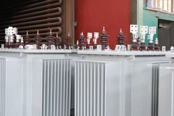
Bushings and Terminals
Facilitating electrical connections:
- Provide insulated passage for conductors entering/exiting the transformer
- High-voltage bushings typically longer for increased insulation
- Low-voltage bushings designed for easier connection to distribution lines
Here’s a quick overview of bushing types:
| Bushing Type | Voltage Level | Key Features |
|---|---|---|
| Porcelain | Up to 36kV | Traditional, robust |
| Polymer | Up to 36kV | Lightweight, high pollution resistance |
| Oil-Impregnated Paper | Higher voltages | Used in larger transformers |
Pressure Relief Devices
Ensuring safety under fault conditions:
- Release internal pressure in case of severe faults
- Prevent tank rupture and oil spills
- Often equipped with indicators for easy fault detection
Nameplate and Auxiliary Equipment
Providing essential information and additional functionality:
- Nameplate displays crucial transformer specifications
- May include oil level indicators, temperature gauges
- Some modern units feature smart monitoring devices
Key points about external components:
- Lightning arresters are crucial for surge protection
- Fuses and disconnects provide overcurrent protection and isolation
- Bushings facilitate safe electrical connections
- Pressure relief devices prevent catastrophic failures
- Nameplates and auxiliary equipment provide important information and monitoring
In my experience, these external components are often the first line of defense against various electrical and environmental hazards. I recall a case where a properly functioning lightning arrester saved a transformer (and likely the connected distribution system) during a severe thunderstorm. The arrester showed signs of activation, but the transformer itself remained unscathed, highlighting the importance of these protective devices.
For example, in a recent rural electrification project, we paid special attention to the selection of bushings for transformers installed in areas with high pollution levels. By choosing polymer bushings with enhanced creepage distance, we significantly reduced maintenance requirements and improved reliability in these challenging environments.
As we move on to discuss typical applications and installation scenarios for pole-mounted transformers, keep these external components in mind. Understanding how they contribute to the overall functionality and safety of the transformer will help you appreciate the complexity of these seemingly simple devices and their critical role in our power distribution infrastructure.
Typical Applications and Installation Scenarios?
Have you ever wondered where and how pole-mounted transformers are typically used? These versatile devices play a crucial role in various power distribution scenarios, but their applications might be more diverse than you think. So, in what situations are pole-mounted transformers most commonly deployed, and what considerations go into their installation?
Pole-mounted distribution transformers are widely used in rural electrification, suburban areas, small commercial zones, and for powering agricultural equipment. They’re ideal for areas with overhead power lines and relatively low power density. Common installation scenarios include roadside utility poles in residential areas, at the edges of farmlands, and near small industrial facilities. Installation typically involves mounting the transformer at least 5 meters above ground on a sturdy pole, with proper clearances for safety and maintenance. Considerations include load requirements, environmental factors, accessibility for maintenance, and local electrical codes.
Key Applications and Installation Considerations
Let’s explore the main aspects:
- Rural and Suburban Power Distribution
- Commercial and Light Industrial Applications
- Agricultural and Remote Area Power Supply
- Installation Height and Clearances
- Environmental and Safety Considerations
Rural and Suburban Power Distribution
Bringing power to less densely populated areas:
- Ideal for areas with overhead distribution lines
- Serves clusters of homes or small communities
- Allows for cost-effective power distribution over larger areas
I recently worked on a project to electrify a remote village. The strategic placement of pole-mounted transformers allowed us to bring power to the entire community at a fraction of the cost of underground distribution.
Commercial and Light Industrial Applications
Powering small businesses and workshops:
- Suitable for strip malls, small offices, and workshops
- Provides necessary power for light machinery and commercial equipment
- Often installed at property boundaries or in dedicated utility areas
During a recent upgrade of a small industrial park, we used pole-mounted transformers to provide power to several small factories. Their compact size and easy installation made them perfect for this application where space was at a premium.
Agricultural and Remote Area Power Supply
Supporting rural development:
- Powers irrigation systems, farm equipment, and rural processing facilities
- Used in remote telecommunication stations and monitoring outposts
- Provides electricity for off-grid or weakly-connected areas
Here’s a quick overview of common agricultural applications:
| Application | Typical Transformer Size | Key Benefit |
|---|---|---|
| Irrigation Systems | 25-50 kVA | Supports multiple pumps |
| Dairy Farms | 50-100 kVA | Handles milking and cooling equipment |
| Grain Storage | 75-150 kVA | Powers aeration and processing equipment |
Installation Height and Clearances
Ensuring safety and accessibility:
- Typically installed at least 5 meters above ground
- Maintain minimum clearances from buildings and other structures
- Consider accessibility for maintenance and repair
Environmental and Safety Considerations
Adapting to local conditions:
- Use corrosion-resistant materials in coastal areas
- Consider wildlife guards in areas with high animal activity
- Implement additional insulation in high-pollution zones
Key points about applications and installation:
- Widely used in rural and suburban power distribution
- Suitable for small commercial and light industrial applications
- Essential for agricultural and remote area power supply
- Proper installation height and clearances are crucial for safety
- Environmental factors significantly influence installation decisions
In my experience, the versatility of pole-mounted transformers makes them invaluable in a wide range of scenarios. I recall a project where we used these transformers to power a series of small eco-lodges in a remote forest area. Their ability to be installed on existing wooden poles minimized environmental impact while providing necessary power for the lodges.
For example, in a recent suburban development project, we strategically placed pole-mounted transformers at regular intervals along the main roads. This approach not only provided efficient power distribution but also allowed for easy future expansion as the community grew.
As we conclude our exploration of pole-mounted distribution transformers, it’s clear that understanding their applications and installation requirements is crucial for effective power system planning. Whether you’re an engineer, project manager, or simply curious about power distribution, this knowledge helps appreciate the complexity and importance of these often-overlooked devices in our electrical infrastructure.
Leading Chinese Manufacturers of Pole-Mounted Distribution Transformers?
Are you looking for reliable suppliers of pole-mounted distribution transformers? With China being a major player in the global electrical equipment market, it’s worth exploring the top manufacturers from this region. But which Chinese companies stand out in producing high-quality, export-ready pole-mounted transformers?
Leading Chinese manufacturers of pole-mounted distribution transformers include CHBEB, CHINT, TBEA, Sieyuan Electric, and Taikai Electric. These companies offer a range of transformers with voltage ratings from 6kV to 35kV and capacities from 10kVA to 500kVA. They are known for their adherence to international standards like IEC and ANSI, competitive pricing, and strong export capabilities. Many of these manufacturers provide customization options, comprehensive documentation, and after-sales support, making them popular choices for international projects in regions like Africa, Southeast Asia, and along the Belt and Road initiative countries.
Overview of Top Chinese Pole-Mounted Transformer Manufacturers
Let’s examine the key players and their offerings:
- CHBEB (China Bei Er Bian)
- CHINT
- TBEA
- Sieyuan Electric
- Taikai Electric
CHBEB (China Bei Er Bian)
Specializing in customized solutions:
- Voltage Range: 6-33kV
- Capacity Range: 10-250 kVA
- Key Features: Strong customization capabilities, professional export packaging, IP54/IP65 options
- Export Markets: Middle East, Africa
I recently visited CHBEB’s manufacturing facility and was impressed by their rigorous testing procedures for export-grade transformers. Their ability to customize units for specific environmental conditions, like high-temperature or high-humidity areas, sets them apart in the international market.
CHINT
Known for reliability and cost-effectiveness:
- Voltage Range: 10-22kV
- Capacity Range: 25-200 kVA
- Key Features: Strong batch delivery capabilities, reasonable pricing, high component integration
- Export Markets: Southeast Asia, Africa
During a recent project in Southeast Asia, we sourced transformers from CHINT. Their ability to deliver a large quantity of standardized units quickly was crucial for meeting our tight project timeline.
TBEA
High-end transformer solutions:
- Voltage Range: 10-35kV
- Capacity Range: 50-500 kVA
- Key Features: Rich experience in national projects, comprehensive documentation
- Export Markets: Central Asia, Belt & Road countries
Here’s a comparison of these top manufacturers:
| Manufacturer | Voltage Range | Capacity Range | Key Strength | Main Export Regions |
|---|---|---|---|---|
| CHBEB | 6-33kV | 10-250 kVA | Customization | Middle East, Africa |
| CHINT | 10-22kV | 25-200 kVA | Cost-effective | Southeast Asia, Africa |
| TBEA | 10-35kV | 50-500 kVA | High-end solutions | Central Asia, Belt & Road |
| Sieyuan | 11-22kV | 50-200 kVA | GIS integration | LATAM, Africa |
| Taikai | 6-20kV | 25-160 kVA | Specialized designs | Vietnam, Pakistan |
Sieyuan Electric
Integrated power solutions provider:
- Voltage Range: 11-22kV
- Capacity Range: 50-200 kVA
- Key Features: GIS system deployment, suitable for remote monitoring integration
- Export Markets: Latin America, Africa
Taikai Electric
Specializing in niche applications:
- Voltage Range: 6-20kV
- Capacity Range: 25-160 kVA
- Key Features: Specialized for rural networks and photovoltaic projects, lightweight structure for easy installation
- Export Markets: Vietnam, Pakistan
Key points about Chinese pole-mounted transformer manufacturers:
- They offer a wide range of voltage and capacity options
- Many provide customization capabilities for specific project needs
- Strong focus on international standards compliance for export markets
- Competitive pricing combined with reliable quality
- Extensive experience in various global markets
In my experience, these Chinese manufacturers have consistently demonstrated their ability to meet diverse project requirements. I recall a large-scale rural electrification project in Africa where we sourced transformers from multiple Chinese manufacturers on this list. By leveraging the specific strengths of each company – such as CHBEB’s customization capabilities for harsh environments and CHINT’s cost-effective standard units for widespread deployment – we were able to optimize the overall power distribution system while managing costs effectively.
For example, in a recent project in a remote area with unstable grid voltage, we utilized Sieyuan Electric’s transformers known for their compatibility with advanced monitoring systems. This choice significantly improved our ability to manage and maintain the transformers in a challenging environment.
When considering Chinese manufacturers for your pole-mounted transformer needs, it’s crucial to evaluate not just the technical specifications and pricing, but also factors like after-sales support, documentation quality, and the manufacturer’s experience in your specific application area. This comprehensive approach will help ensure you select the right partner for your power distribution projects.
FAQs: Understanding Pole Distribution Transformers?
Are you still puzzled by some aspects of pole-mounted distribution transformers? You’re not alone. Many professionals and curious individuals have questions about these essential components of our power distribution system. Let’s address some of the most frequently asked questions to deepen your understanding.
FAQs about pole distribution transformers often cover their working principle, internal components, common voltage ratings, and installation procedures. The working principle is based on electromagnetic induction, where changing magnetic fields in the primary winding induce voltage in the secondary winding. Key internal components include the core, windings, and insulating oil. Common voltage ratings are 11kV/400V or 22kV/400V, with capacities ranging from 25kVA to 250kVA. Installation typically involves mounting the transformer at least 5 meters high on a sturdy pole, with proper clearances and safety equipment like surge arresters and fuses.
Frequently Asked Questions About Pole Distribution Transformers
Let’s address some common queries:
- Working Principle of Pole Transformers
- Internal Components and Their Functions
- Common Voltage and kVA Ratings
- Installation Procedures and Requirements
- Maintenance and Lifespan Considerations
Working Principle of Pole Transformers
Q: How does a pole-mounted transformer work?
A: Pole-mounted transformers work on the principle of electromagnetic induction. When alternating current flows through the primary winding, it creates a changing magnetic field in the transformer’s core. This changing field induces a voltage in the secondary winding. The ratio of turns in the primary and secondary windings determines the voltage transformation ratio.
I often use a simple analogy to explain this: imagine the transformer as a gear system, where the number of teeth on each gear represents the number of turns in each winding. Just as gears can change speed and torque, transformers change voltage and current levels.
Internal Components and Their Functions
Q: What are the main components inside a pole-mounted transformer?
A: The key internal components are:
- Core: Usually made of laminated silicon steel, provides a path for magnetic flux
- Windings: Primary (high-voltage) and secondary (low-voltage) coils, typically copper or aluminum
- Insulating Oil: Provides cooling and electrical insulation
- Tank: Houses all components and is filled with insulating oil
During a recent educational workshop, we disassembled an old pole transformer. Seeing these components firsthand greatly enhanced the participants’ understanding of how each part contributes to the transformer’s function.
Common Voltage and kVA Ratings
Q: What are typical voltage and capacity ratings for pole transformers?
A: Common ratings include:
| Primary Voltage | Secondary Voltage | Typical Capacities |
|---|---|---|
| 11kV | 400V | 25, 50, 100 kVA |
| 22kV | 400V | 50, 100, 160 kVA |
| 33kV | 400V | 100, 160, 250 kVA |
These ratings can vary based on specific regional standards and requirements.
Installation Procedures and Requirements
Q: How is a pole-mounted transformer typically installed?
A: Installation generally involves:
- Mounting the transformer at least 5 meters above ground on a sturdy pole
- Ensuring proper clearances from buildings and other structures
- Installing protective devices like surge arresters and fuses
- Connecting primary and secondary lines through appropriate bushings
- Proper grounding of the transformer tank and neutral point
I recently oversaw the installation of several pole transformers in a suburban development. The precision required in positioning and connecting these units, especially considering safety clearances, was impressive.
Maintenance and Lifespan Considerations
Q: What maintenance do pole transformers require, and how long do they last?
A: Maintenance typically includes:
- Regular visual inspections for signs of damage or oil leaks
- Periodic oil testing to check for contamination or degradation
- Cleaning of bushings and external surfaces
- Checking and tightening of connections
With proper maintenance, pole-mounted transformers can last 20-30 years or more.
Key points from these FAQs:
- The working principle is based on electromagnetic induction
- Core, windings, and insulating oil are the main internal components
- Voltage and capacity ratings vary to suit different distribution needs
- Proper installation is crucial for safety and performance
- Regular maintenance can significantly extend a transformer’s lifespan
In my experience, understanding these fundamental aspects is crucial for anyone involved in power distribution projects. I recall a situation where a maintenance team’s thorough understanding of transformer components and typical failure modes helped them quickly diagnose and resolve an issue, minimizing downtime for an entire neighborhood.
For example, during a recent rural electrification project, we used these FAQs as a basis for training local technicians. This knowledge empowered them to perform basic maintenance and troubleshooting, greatly improving the long-term sustainability of the power distribution system.
Remember, while these FAQs provide a good overview, always consult manufacturer specifications and local regulations for detailed information specific to your situation. Continuous learning and staying updated on the latest developments in transformer technology are key to effectively managing and maintaining these crucial components of our power infrastructure.
Conclusion
Pole distribution transformers are crucial components in power distribution systems, stepping down medium voltage to usable levels for end consumers. Understanding their structure, working principle, and key components is essential for effective selection, installation, and maintenance. From the core and windings to external protective devices, each element plays a vital role in ensuring reliable and efficient power delivery. As technology advances, these transformers continue to evolve, adapting to new challenges in our ever-growing power needs.
I believe that sharing knowledge is crucial in this rapidly changing field. That’s why I’m committed to providing accessible, in-depth information about power systems, including topics like transformer structure and operation. My goal is to
