Have you ever wondered what’s really inside those mysterious boxes that power our world? Transformers are everywhere, but their inner workings often remain a mystery. What if you could understand these crucial devices as easily as you understand your smartphone?
A transformer consists of three main internal components: the core, windings, and insulation system. The core, typically made of silicon steel, provides a path for magnetic flux. Windings, usually copper or aluminum, transfer energy between circuits. The insulation system, which may use oil, paper, or resin, prevents short circuits and overheating. Understanding these parts helps in selecting, installing, and maintaining transformers effectively, potentially saving costs and extending equipment lifespan.
In this guide, I’ll take you on a journey inside a transformer, explaining each component in simple terms. Whether you’re an engineer, a project manager, or simply curious about the technology that powers our world, this article will give you a clear understanding of transformer internals. Let’s demystify these essential devices together.
What Are the Main Internal Parts of a Transformer?
Have you ever looked at a transformer and wondered what’s actually inside that metal box? You’re not alone. Many people, even those working with electrical systems, are unclear about the internal structure of these crucial devices. But what if understanding these components could help you make better decisions about power distribution in your projects?
The main internal parts of a transformer are the core, windings, and insulation system. The core, typically made of laminated steel sheets, provides a path for magnetic flux. Windings, consisting of primary and secondary coils, transfer energy between circuits. The insulation system, which may include oil, paper, or resin, prevents short circuits and manages heat. Additional components include terminals for connections, a cooling system, and protective devices like Buchholz relays in larger units.
Key Components of a Transformer
Let’s break down the main internal parts:
- Core
- Windings
- Insulation System
- Terminals and Bushings
- Cooling System
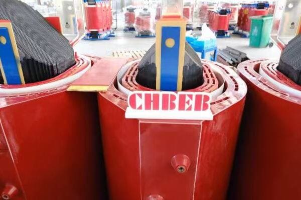
Core
The magnetic heart of the transformer:
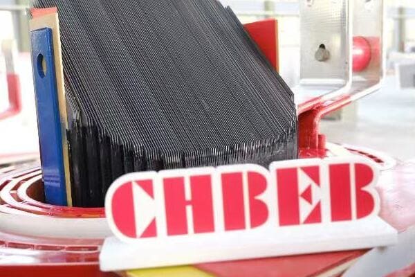
- Made of thin laminated steel sheets
- Provides a low-reluctance path for magnetic flux
- Shapes include E-I, U-I, or toroidal designs
I recently inspected a disassembled 1000kVA transformer. The core’s laminated structure was fascinating – hundreds of thin steel sheets stacked together, each coated with insulating material to reduce eddy current losses.
Windings
Conducting the electrical magic:
- Primary winding: Connects to input voltage
- Secondary winding: Delivers output voltage
- Made of copper or aluminum wire
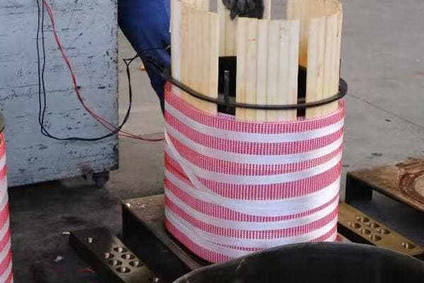
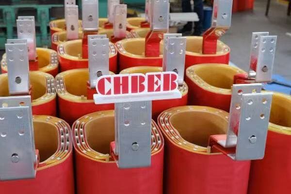
During a factory tour, I observed the winding process for a large transformer. The precision in layering each turn of wire, ensuring proper insulation between layers, was impressive and crucial for the transformer’s performance.
Insulation System
Protecting and cooling:
- In oil-filled transformers: Mineral oil and paper insulation
- In dry-type transformers: Air, resin, or other solid insulators
- Prevents short circuits and manages heat dissipation
Here’s a quick comparison of insulation types:
| Transformer Type | Primary Insulation | Characteristics |
|---|---|---|
| Oil-filled | Mineral oil + paper | Excellent cooling, high dielectric strength |
| Dry-type | Epoxy resin or air | Environmentally friendly, fire-resistant |
Terminals and Bushings
Connecting to the outside world:
- Bushings: Insulated passages for conductors
- Terminals: Connection points for external circuits
Cooling System
Managing heat for longevity:
- Oil-filled: Radiators or fans for oil circulation
- Dry-type: Natural air circulation or forced-air cooling
Key points about transformer internal parts:
- The core provides a path for magnetic flux transfer
- Windings transform voltage levels through electromagnetic induction
- Insulation systems prevent short circuits and manage heat
- Terminals and bushings allow for safe external connections
- Cooling systems are crucial for maintaining optimal operating temperatures
In my experience, understanding these internal components is crucial for effective transformer management. I recall a case where a client was experiencing frequent overheating issues with their transformer. By examining the internal structure, we discovered that the insulation system had degraded, reducing its heat dissipation efficiency. This knowledge allowed us to address the root cause rather than just treating symptoms.
For example, in a recent project involving the selection of transformers for a new data center, our understanding of internal components led us to choose a specific dry-type design with enhanced cooling capabilities. This choice was crucial given the high ambient temperatures and continuous load requirements of the facility.
As we move on to discuss the transformer core in more detail, keep these basic components in mind. Understanding how they interact will help you grasp the overall function and efficiency of these essential devices.
The Transformer Core: Material, Shape, and Magnetic Function?
Have you ever wondered why transformer cores are made of specific materials or shaped in particular ways? Many people overlook the importance of the core, focusing only on ratings and size. But what if understanding the core could help you choose more efficient transformers or diagnose issues more effectively?
The transformer core is typically made of thin laminations of silicon steel, also known as electrical steel or CRGO (Cold Rolled Grain Oriented) steel. Its primary function is to provide a low-reluctance path for magnetic flux, facilitating energy transfer between windings. Common core shapes include E-I, U-I, and toroidal designs, each offering different efficiency and manufacturing trade-offs. The core’s material and construction significantly impact the transformer’s efficiency, affecting factors like no-load losses and magnetizing current.
Key Aspects of Transformer Cores
Let’s examine the main features:
- Core Materials
- Core Shapes and Designs
- Magnetic Function
- Impact on Transformer Efficiency
- Manufacturing Considerations
Core Materials
Optimizing magnetic properties:
- Silicon Steel (CRGO): Most common, excellent magnetic properties
- Amorphous Metal: Higher efficiency, but more expensive
- Ferrite: Used in high-frequency applications
I recently visited a transformer manufacturing plant where they were experimenting with amorphous metal cores. The reduction in core losses was impressive, though the material’s brittleness presented unique manufacturing challenges.
Core Shapes and Designs
Balancing efficiency and practicality:
- E-I Core: Common in smaller transformers, easy to assemble
- U-I Core: Better flux distribution, used in larger units
- Toroidal Core: Highest efficiency, but more difficult to manufacture
During a recent project, we compared E-I and toroidal core designs for a series of 500kVA transformers. While the toroidal cores offered slightly better efficiency, the E-I design was chosen for its easier maintenance and lower manufacturing cost.
Magnetic Function
Understanding the core’s role:
- Provides a low-reluctance path for magnetic flux
- Concentrates magnetic field to maximize coupling between windings
- Minimizes magnetic flux leakage
Here’s a simplified view of how different core materials perform:
| Core Material | Advantages | Disadvantages |
|---|---|---|
| Silicon Steel | Cost-effective, good performance | Higher losses than advanced materials |
| Amorphous Metal | Very low core losses | More expensive, challenging to manufacture |
| Ferrite | Excellent for high frequencies | Limited power handling capacity |
Impact on Transformer Efficiency
Core’s influence on performance:
- Affects no-load losses (core losses)
- Influences magnetizing current
- Determines transformer’s overall efficiency
Manufacturing Considerations
Balancing performance and producibility:
- Lamination thickness affects both losses and manufacturing complexity
- Core assembly methods impact production speed and cost
- Material choice influences tooling and handling requirements
Key points about transformer cores:
- Material choice significantly impacts efficiency and cost
- Core shape affects flux distribution and manufacturing ease
- The core’s primary function is to provide a path for magnetic flux
- Core design directly influences transformer efficiency
- Manufacturing considerations play a role in core selection
In my experience, the choice of core material and design can have a profound impact on transformer performance. I recall a project where we were tasked with upgrading transformers in an old industrial facility. By replacing the old silicon steel cores with modern, high-grade electrical steel, we achieved a significant reduction in core losses, leading to improved overall efficiency and reduced operating costs.
For example, in a recent renewable energy project, we specified transformers with amorphous metal cores for the main step-up units. Despite the higher initial cost, this choice was justified by the lower losses, which were particularly beneficial given the variable nature of wind power generation. The improved efficiency translated to measurable increases in energy output over the project’s lifetime.
As we move on to discuss transformer windings, keep in mind how the core interacts with these components. Understanding this relationship is key to grasping the overall function and efficiency of transformers.
Windings: Primary vs Secondary and the Role of Copper or Aluminum?
Have you ever wondered why some transformers use copper windings while others use aluminum? Or why the primary and secondary windings are designed differently? These choices can significantly impact a transformer’s performance, cost, and lifespan. But how do you know which option is best for your application?
Transformer windings consist of primary and secondary coils, responsible for voltage transformation. The primary winding receives input voltage, while the secondary delivers the output. Copper and aluminum are the most common winding materials, each with distinct advantages. Copper offers better conductivity and compact design but at a higher cost. Aluminum is lighter and more economical but requires larger windings for the same capacity. The choice between these materials, along with winding design (e.g., layer, disc, or helical), affects the transformer’s efficiency, size, and price.
Key Aspects of Transformer Windings
Let’s examine the main features:
- Primary vs Secondary Windings
- Copper vs Aluminum Conductors
- Winding Designs and Configurations
- Impact on Transformer Performance
- Economic Considerations
Primary vs Secondary Windings
Understanding the basics:
- Primary Winding: Connected to input voltage source
- Secondary Winding: Delivers transformed voltage to the load
- Turn ratio determines voltage transformation
I recently inspected a 2000kVA transformer where the primary winding had significantly fewer turns of thicker wire compared to the secondary. This visual representation of the turns ratio principle was a great practical example of transformer theory in action.
Copper vs Aluminum Conductors
Choosing the right material:
- Copper: Higher conductivity, smaller size, better heat dissipation
- Aluminum: Lighter weight, lower cost, larger size for same capacity
During a recent project, we had to decide between copper and aluminum windings for a series of distribution transformers. While copper offered better performance, the aluminum option provided significant cost savings without compromising on the required efficiency standards.
Winding Designs and Configurations
Optimizing for different applications:
- Layer Winding: Common in low-voltage applications
- Disc Winding: Used in high-voltage transformers
- Helical Winding: Offers good short-circuit strength
Here’s a comparison of winding materials:
| Material | Advantages | Disadvantages |
|---|---|---|
| Copper | Higher conductivity, Compact design | More expensive, Heavier |
| Aluminum | Lower cost, Lighter weight | Larger size, Higher resistance |
Impact on Transformer Performance
How windings affect efficiency:
- Conductor material influences load losses
- Winding design affects short-circuit strength
- Insulation between turns impacts voltage withstand capability
Economic Considerations
Balancing cost and performance:
- Material prices fluctuate, affecting overall transformer cost
- Lifecycle cost analysis often favors copper for long-term applications
- Aluminum can be more economical for certain voltage classes and sizes
Key points about transformer windings:
- Primary and secondary windings serve distinct functions in voltage transformation
- The choice between copper and aluminum impacts performance and cost
- Various winding designs are used to optimize for different applications
- Winding characteristics significantly affect transformer efficiency and reliability
- Economic factors play a crucial role in winding material selection
In my experience, the choice of winding material and design can have far-reaching implications. I recall a project for a large industrial facility where we initially specified aluminum windings to reduce costs. However, after conducting a detailed lifecycle cost analysis, including efficiency losses and potential replacement costs, we ultimately chose copper windings. The higher initial investment was justified by long-term energy savings and improved reliability.
For example, in a recent renewable energy project, we used a hybrid approach. The main step-up transformers used copper windings for maximum efficiency, while the smaller distribution transformers in the solar farm used aluminum windings to balance cost and performance. This strategic use of different winding materials helped optimize the overall system efficiency while managing project costs.
As we move on to discuss transformer insulation systems, keep in mind how windings interact with both the core and insulation. Understanding these relationships is crucial for grasping the overall design and performance of transformers.
Transformer Insulation System: How It Works and Why It Matters?
Have you ever considered what keeps the high-voltage components of a transformer from short-circuiting? The insulation system is a critical yet often overlooked aspect of transformer design. But why is it so important, and how does it actually work to keep transformers safe and efficient?
The transformer insulation system is a crucial component that prevents electrical breakdown between windings, core, and other conductive parts. It typically consists of liquid (oil) or solid (resin, paper) materials with high dielectric strength. In oil-filled transformers, mineral oil combined with cellulose paper provides both insulation and cooling. Dry-type transformers use materials like epoxy resin or Nomex paper. The insulation system not only prevents short circuits but also manages heat dissipation, protects against moisture, and significantly influences the transformer’s lifespan and reliability.
Key Aspects of Transformer Insulation
Let’s examine the main features:
- Types of Insulation Systems
- Functions of Insulation
- Oil-Filled vs Dry-Type Insulation
- Aging and Maintenance of Insulation
- Impact on Transformer Performance and Lifespan
Types of Insulation Systems
Common insulation materials:
- Liquid Insulation: Mineral oil, silicone oil, natural esters
- Solid Insulation: Cellulose paper, Nomex paper, epoxy resin
- Combination Systems: Oil-paper insulation in oil-filled transformers
I recently inspected a 30-year-old oil-filled transformer where the oil had maintained its insulating properties remarkably well. This experience highlighted the longevity and effectiveness of well-maintained liquid insulation systems.
Functions of Insulation
Multi-faceted role in transformer operation:
- Electrical Insulation: Prevents short circuits between conductive parts
- Heat Dissipation: Transfers heat from windings to cooling systems
- Moisture Protection: Shields critical components from humidity
- Mechanical Support: Provides structural integrity to windings
During a recent factory tour, I observed the intricate process of applying epoxy resin insulation to dry-type transformer windings. The precision required to ensure complete coverage and void-free insulation was impressive.
Oil-Filled vs Dry-Type Insulation
Comparing insulation systems:
- Oil-Filled: Excellent cooling and insulation, but potential environmental concerns
- Dry-Type: Environmentally friendly, fire-resistant, but typically lower capacity
Here’s a quick comparison:
| Aspect | Oil-Filled Insulation | Dry-Type Insulation |
|---|---|---|
| Cooling Efficiency | Excellent | Good |
| Environmental Risk | Higher (oil leaks) | Minimal |
| Fire Safety | Lower | Higher |
| Maintenance | Regular oil testing required | Minimal maintenance |
Aging and Maintenance of Insulation
Ensuring long-term reliability:
- Oil Degradation: Monitored through regular oil analysis
- Paper Deterioration: Accelerated by heat, moisture, and oxygen
- Dry-Type Aging: Affected by environmental factors and load cycles
Impact on Transformer Performance and Lifespan
Critical role in long-term operation:
- Insulation Quality: Directly affects transformer’s voltage withstand capability
- Thermal Management: Influences loading capacity and efficiency
- Lifespan Determination: Often the limiting factor in transformer longevity
Key points about transformer insulation systems:
- Insulation prevents electrical breakdown and manages heat
- Different types of insulation suit various transformer designs and applications
- Oil-filled and dry-type systems have distinct advantages and challenges
- Proper maintenance of insulation is crucial for transformer longevity
- Insulation quality significantly impacts overall transformer performanceIn my experience, the choice and maintenance of insulation systems can make or break a transformer’s performance and lifespan. I recall a case where a client was experiencing frequent transformer failures in a humid, coastal environment. Upon investigation, we discovered that the insulation system was not adequately protected against moisture ingress. By upgrading to a more suitable insulation system with enhanced moisture resistance, we significantly improved the transformers’ reliability and extended their operational life.
For example, in a recent project for a data center, we specified dry-type transformers with advanced epoxy resin insulation. This choice was driven by the need for high fire safety standards and minimal maintenance requirements in a critical facility. The enhanced insulation system not only met the stringent safety requirements but also provided excellent thermal management, crucial for the continuous high-load operation typical in data centers.
As we move on to visually compare the internals of dry-type and oil-immersed transformers, keep in mind how the insulation system integrates with other components. Understanding this integration is key to appreciating the overall design and functionality of different transformer types.
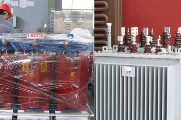
Visual Overview: What’s Inside a Dry Type vs Oil Immersed Transformer?
Have you ever wondered how dry type and oil immersed transformers differ internally? Many people struggle to visualize these differences, which can lead to confusion when selecting or maintaining transformers. But what if you could see inside both types, side by side?
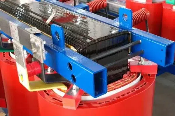
Dry type and oil immersed transformers have distinct internal structures. Dry type transformers feature exposed or resin-encapsulated windings, with air or epoxy resin as the primary insulation and cooling medium. They often have an open structure or are enclosed in a ventilated cabinet. Oil immersed transformers, conversely, have their core and windings submerged in insulating oil within a sealed tank. They typically include additional components like radiators for cooling, an expansion tank (conservator) for oil volume changes, and various monitoring devices like oil level indicators and pressure relief valves.
Key Differences in Internal Structure
Let’s compare the main internal components:
- Core and Winding Arrangement
- Insulation and Cooling System
- Enclosure and External Components
- Monitoring and Protection Devices
- Size and Space Requirements
Core and Winding Arrangement
Structural differences:
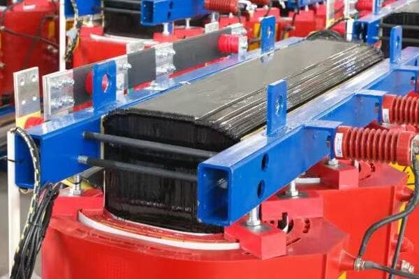
- Dry Type: Often visible windings, sometimes resin-encapsulated
- Oil Immersed: Core and windings fully submerged in oil
I recently had the opportunity to compare a 1000kVA dry type transformer with an oil immersed unit of the same capacity. The stark contrast in their internal layouts was fascinating – the dry type’s exposed windings versus the oil-filled tank of the immersed unit.
Insulation and Cooling System
Different approaches to insulation and heat management:
- Dry Type: Air or solid insulation (e.g., epoxy resin), often with forced air cooling
- Oil Immersed: Oil serves as both insulator and coolant, often with external radiators
During a factory tour, I observed the manufacturing process for both types. The precision required in resin casting for dry type transformers was as impressive as the meticulous oil filling and sealing process for oil immersed units.
Enclosure and External Components
Visible differences in design:
- Dry Type: Often in ventilated cabinets or with exposed components
- Oil Immersed: Sealed tank with external components like radiators and conservators
Here’s a quick comparison of external features:
| Feature | Dry Type Transformer | Oil Immersed Transformer |
|---|---|---|
| Main Enclosure | Ventilated cabinet or open frame | Sealed oil tank |
| Cooling System | Fans (if forced air) | Radiators, sometimes with fans |
| Expansion System | Not required | Conservator tank |
| Monitoring Devices | Temperature sensors | Oil level gauge, pressure relief valve |
Monitoring and Protection Devices
Different safety and monitoring needs:
- Dry Type: Temperature monitors, sometimes partial discharge sensors
- Oil Immersed: Oil level indicators, pressure relief devices, Buchholz relay
Size and Space Requirements
Comparing footprints and installation needs:
- Dry Type: Generally more compact, suitable for indoor installation
- Oil Immersed: Larger footprint, often requires containment area for potential oil leaks
Key points about the internal differences:
- Core and winding arrangements differ significantly between types
- Insulation and cooling methods are fundamentally different
- External components vary based on the cooling and insulation needs
- Monitoring and protection devices are tailored to each type’s specific risks
- Size and installation requirements can differ substantially
In my experience, understanding these internal differences is crucial for proper selection and installation. I recall a project where a client initially wanted to replace an old oil immersed transformer with a dry type unit in the same location. However, after reviewing the internal structures and space requirements, we realized that significant modifications to the installation site would be necessary. This insight helped the client make a more informed decision about whether to upgrade or maintain the existing transformer type.
For example, in a recent hospital expansion project, we chose dry type transformers for their fire safety advantages and lower maintenance requirements. The ability to install these units closer to the load centers, due to their compact size and absence of oil, allowed for a more efficient power distribution design throughout the facility.
As we conclude our exploration of transformer internals, remember that understanding these structural differences is key to making informed decisions about transformer selection, installation, and maintenance. Whether you’re an engineer, facility manager, or project planner, this knowledge can help you optimize your power distribution systems for safety, efficiency, and reliability.
Why Understanding Transformer Structure Helps with Selection and Maintenance?
Have you ever wondered why some transformers fail prematurely or why certain types are preferred for specific applications? The key often lies in understanding the internal structure of transformers. But how exactly does this knowledge translate into better selection and maintenance practices?
Understanding transformer structure is crucial for optimal selection and maintenance. It helps in choosing the right type (dry or oil-immersed) for specific environments, assessing cooling needs based on load profiles, and anticipating maintenance requirements. Knowledge of core and winding materials aids in evaluating efficiency and long-term costs. Familiarity with insulation systems helps predict lifespan and maintenance needs. This understanding enables more informed decisions during procurement, more effective troubleshooting during operation, and more efficient maintenance scheduling, ultimately leading to improved reliability and cost-effectiveness of power distribution systems.
Key Benefits of Understanding Transformer Structure
Let’s explore how this knowledge helps:
- Improved Selection Process
- Enhanced Maintenance Practices
- Better Troubleshooting Capabilities
- Optimized Performance and Efficiency
- Increased Safety and Reliability
Improved Selection Process
Making informed choices:
- Matching transformer type to environmental conditions
- Selecting appropriate cooling systems based on load profiles
- Choosing the right insulation class for expected operating temperatures
I recently advised a client on transformer selection for a coastal industrial facility. Understanding the internal structure helped us choose a design with enhanced corrosion resistance for the core and windings, crucial for the salt-laden environment.
Enhanced Maintenance Practices
Tailoring maintenance to specific needs:
- Focusing on critical components based on transformer type
- Anticipating wear and degradation patterns
- Scheduling appropriate maintenance intervals
During a recent maintenance review for a large data center, our knowledge of dry-type transformer internals allowed us to develop a more targeted and efficient maintenance plan, focusing on critical areas like winding insulation and cooling systems.
Better Troubleshooting Capabilities
Diagnosing issues more effectively:
- Identifying potential failure points based on structural knowledge
- Interpreting test results with a deeper understanding of internal components
- Quickly pinpointing the root cause of performance issues
Here’s how structural knowledge aids in common troubleshooting scenarios:
| Issue | How Structural Knowledge Helps |
|---|---|
| Overheating | Identify if it’s a core, winding, or cooling system problem |
| Unusual Noise | Determine if it’s core vibration or winding movement |
| Insulation Failure | Assess whether it’s due to overloading, aging, or environmental factors |
Optimized Performance and Efficiency
Maximizing transformer capabilities:
- Understanding load capacity in relation to core and winding design
- Optimizing cooling systems based on internal heat generation patterns
- Balancing efficiency with cost based on core material properties
Increased Safety and Reliability
Enhancing operational safety:
- Recognizing potential failure modes based on structural weaknesses
- Implementing appropriate safety measures for different transformer types
- Improving reliability through targeted upgrades and replacements
Key points about the importance of understanding transformer structure:
- It enables more informed and appropriate transformer selection
- Maintenance can be tailored to specific transformer designs
- Troubleshooting becomes more efficient and accurate
- Performance and efficiency can be optimized based on structural knowledge
- Safety and reliability are enhanced through better understanding of potential issues
In my experience, a deep understanding of transformer structure can lead to significant improvements in both selection and maintenance practices. I recall a case where a manufacturing plant was experiencing frequent transformer failures. By analyzing the internal structure of the failing units, we discovered that the core design was not suitable for the harmonic-rich environment of the plant. This insight led to the selection of transformers with more appropriate core designs, dramatically improving reliability and reducing downtime.
For example, in a recent renewable energy project, our understanding of transformer internals guided us in selecting units with amorphous metal cores. While more expensive initially, these transformers offered superior efficiency, especially under the variable load conditions typical of wind and solar generation. This choice led to measurable improvements in overall system efficiency and reduced long-term operational costs.
Remember, whether you’re selecting a new transformer or maintaining existing ones, a solid grasp of internal structures and components is invaluable. It empowers you to make decisions that enhance performance, extend equipment life, and ultimately contribute to more reliable and efficient power distribution systems.
Conclusion
Understanding the internal structure of transformers – core, windings, and insulation – is crucial for effective selection, operation, and maintenance. This knowledge helps in choosing the right transformer for specific applications, optimizing performance, and implementing targeted maintenance strategies. By grasping these fundamentals, you can make more informed decisions, troubleshoot issues effectively, and ultimately ensure more reliable and efficient power distribution systems.
Remember, at chbeb-ele, we’re not just sharing information – we’re empowering you to be part of the solution in creating a secure, clean, and efficient energy future. Let’s continue this journey together.
