Step-Up Transformers and Medium Voltage Distribution: The Seamless Connection for Power Grids
Introduction
One of the biggest problems with power systems is getting electricity to where it has to go. If you don’t have the correct transformer approach, you lose a lot of energy, expenses go up, and reliability goes down. Step-up transformers and medium voltage (MV) distribution work well together to fix this problem. Let’s find out how they are connected in current power systems.
I. Why should you step up? Understanding the Main Purpose of Step-Up Transformers
Problem: Moving a lot of power at low voltage consumes energy. Agitate: Losses grow with current, making the grid’s economics worse. Step-up transformers raise voltage and lower current, which cuts down on line losses and makes transmission cheaper.
The Science of Stepping Up: Why More Voltage Means Less Loss
The formula for conduction losses on a line is Ploss = I²R1. When the voltage goes up, the current goes down for a given power: P = V × I. If you double the voltage, the current goes down by half and the resistive losses go down by a quarter. Step-up transformers make this high-voltage, low-current system possible so that power plants can send electricity over hundreds of kilometers without losing too much power.
- Less copper loss: Lower current cuts down on I²R heating in conductors and transformer windings.
- Thinner wires or greater spans make transmission lighter and cheaper.
- Better stability margins: Lower losses mean better voltage profiles and more room for heat.
Quick lens: 220 kV lines carry around 10 times less current than 220 kV lines with the same megawatt flow.
How Step-Up Transformers Work and What They Are Used For
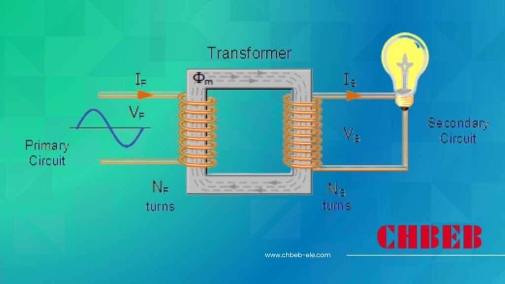
A step-up transformer has more secondary turns than primary turns, which employs electromagnetic induction to enhance the secondary voltage. The apparent power stays about the same (minus losses) even when the voltage goes up and the current goes down. The goal is simple: provide a lot of electricity across long distances at a low cost, and then reduce it near loads.
- The MVA rating, primary and secondary voltage, vector group, impedance, short-circuit withstand, BIL, cooling (ONAN/ONAF/ODAF), tap-changer type (on-load/off-circuit), and standards (IEC/IEEE) are all important features that purchasers look at.
- Levers of reliability include the core material, the winding design, the insulation class, the management of partial discharge, and the monitoring of the oil and winding temperatures.
II. The Grid’s “Last Mile”: From High Voltage Transmission to MV Distribution
Problem: Facilities can’t use or safely work with extra-high voltage. Power is meaningless and harmful without the correct step-down. MV distribution connects transmission to local networks, transmitting power at safe voltages with protection and management.
What does “Medium Voltage Distribution” mean? Common Uses and Voltage Levels
Depending on where you are, medium voltage is usually between 1 kV and 35 kV2. It provides power to cities, campuses, factories, business districts, and utility customers through MV feeders and distribution transformers that finally drop the voltage to LV (e.g., 400/230 V) for use.
| Typical MV Level | Regions / Notes | Common Applications |
|---|---|---|
| 10–11 kV | Asia, EMEA utilities | Urban feeders, factories, hospitals, schools |
| 13.8–15 kV | North America, LATAM | Campuses, data centers, commercial districts |
| 20–22 kV | EU, Middle East | Industrial parks, municipal networks |
| 27.6 kV | Canada | Suburban feeders, long MV runs |
| 33–35 kV | Global | Regional MV backbones, renewable collection |
- MV assets: Primary substations (HV/MV), ring-main units (RMUs), reclosers, sectionalizers, capacitor banks, voltage regulators, distribution transformers, protection relays, SCADA/RTUs.
- Customer interface: Pad-mounted or unit substations that power LV switchboards and final circuits.
The MV Distribution Network’s Structure and Main Problems
MV networks can be simple and cheap, like a radial network, or more reliable, like a looped or meshed network. Today’s problems are about resilience, power quality, and combining variable renewables with electric vehicle loads without raising the risk of outages or operational costs.
- Long feeders, DER backfeed, and daytime PV peaks drive tap operations and regulator sizing for voltage regulation.
- Protection coordination: Inverter-based resources change fault currents, therefore relays need to be retuned to be more sensitive and selective.
- Harmonics, flicker, and imbalance in power quality need filters, tuning of capacitors and reactors, and management of three-phase loads.
- Reliability: FLISR (fault localization, isolation, service restoration), automation, and reclosers all help lower SAIDI/SAIFI.
- Storm hardening, undergrounding, arc-flash reduction, and condition monitoring (DGA, PD, thermal) all help with safety and resilience.
III. The synergy of step-up transformers and MV distribution from generation to consumption
Problem: It doesn’t matter how efficiently power is generated if it stops before it gets to users. Agitate: If you don’t deliver MV or if you don’t transmit it well, the chain breaks. Answer: Step-up From plant to plug, GSUs and MV networks function together as one.
Use Cases in Power Plants and Renewable Energy
In a conventional power plant, the generator terminals are between 11 and 20 kV. A generator step-up (GSU) boosts this to 110–500 kV (or greater) so it can be sent. An HV/MV substation near load centers drops down to, say, 33 kV. MV feeders send power to districts, where distribution transformers send LV to buildings.
- Thermal and hydro: High GSU MVA values, small impedance windows, and strong cooling for continuous duty.
- The grid interface uses on-load tap changers (OLTC) and AVR to work with transmission operators to keep the voltage steady.
Wind or solar farm: The turbines and inverters put out power at LV/MV (0.69–34.5 kV). Collection step-up transformers combine outputs into a range of 66 to 220 kV for export. Downstream, MV distribution takes in renewable flows and keeps things stable by using voltage regulation, capacitor banks, and, more and more, storage.
- Collector systems: A major substation step-up connects pad-mounted transformers at each turbine/string.
- Operational focus: curtailment logic, ride-through compliance, reactive power support, and ramp-rate management.
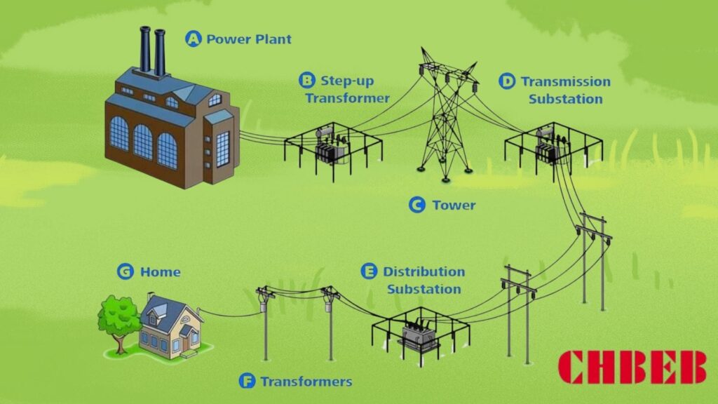
Flow at a glance: Generator (11–20 kV) → GSU Step-Up (110–500 kV) → Transmission → HV/MV Substation (e.g., 220/33 kV) → MV Feeders (33/11 kV) → Distribution Transformers → LV Loads (400/230 V).(110–500 kV) -> Transmission → HV/MV
What will happen in the future: problems and chances in smart grids and distributed generation
Digitalization and decentralization tighten the link between step-up assets and MV operations. Expect more sensors, automation, and power electronics to enhance flexibility, reliability, and efficiency—while managing bi-directional flows and new load shapes.
- DERMS and orchestration: Distributed energy resource management solutions manage PV, wind, storage, and controllable loads across MV feeds.
- Advanced transformers: OLTC on distribution transformers, ester oils, and new solid-state ideas for faster, more precise voltage management.
- Edge intelligence: µPMUs, smart reclosers, and FLISR make things easier to see and fix themselves after problems.
- BESS and high-power chargers move peaks and offer voltage profiles for MV storage and EV fast charging.
- Condition-based maintenance: Online DGA, thermal/PD sensors, and analytics help transformers last longer and reduce downtime.
Conclusion
Step-up transformers and MV distribution work together to move a lot of energy quickly and safely. Mastering both makes your grid and projects more resilient, lowers losses, and gets them ready for a smarter, cleaner energy future.
- Power Loss in Transmission Lines, All About Circuits — ↩︎
- Medium Voltage Technical Guide, Schneider Electric — ↩︎
Learn More About CHBEB Transformers
Want to explore more transformer solutions for your project? Download our product catalog or browse our product categories to find the right fit for your needs.📥 Download Product Catalog🔎 Browse Product Categories
