Are you puzzled by the complex inner workings of power transformers? You’re not alone. Many engineers and technicians struggle to grasp the intricacies of these vital devices.
This comprehensive guide explores seven critical internal components of power transformers: core and windings, bushings, tap changers, cooling systems, pressure relief devices, silica gel breathers, and smart monitoring systems. Understanding these components is crucial for efficient operation and maintenance.

As someone who’s spent years working with power transformers, I’ve seen how crucial it is to understand these internal devices. Let’s dive into the heart of transformer technology and unravel its mysteries together.
Transformer Core & Windings: The Heart of Voltage Conversion?
Have you ever wondered how transformers magically change voltage levels? The secret lies in the core and windings, the true heroes of voltage conversion.
The transformer core and windings are the primary components responsible for voltage transformation. The core provides a path for magnetic flux, while the windings create and receive this flux, enabling the transfer of electrical energy between circuits at different voltage levels.
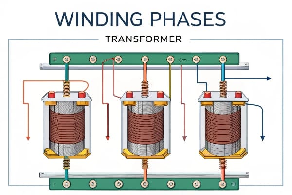
In my years of experience, I’ve come to appreciate the elegance of this seemingly simple yet powerful mechanism. Let’s break it down:
The Core: Magnetic Maestro
-
Purpose:
- Provides a low-reluctance path for magnetic flux
- Concentrates the magnetic field
-
Construction:
- Made of thin laminations of silicon steel
- Laminations reduce eddy current losses
-
Types:
- Core-type: Windings surround the core legs
- Shell-type: Core surrounds the windings
Windings: Copper Conductors
-
Primary Winding:
- Receives input electrical energy
- Creates changing magnetic field in the core
-
Secondary Winding:
- Induced voltage from the changing magnetic field
- Delivers output electrical energy
-
Materials:
- Typically copper or aluminum
- Insulated to prevent short circuits
The Transformation Process
| Step | Action | Result |
|---|---|---|
| 1 | AC input to primary winding | Creates changing magnetic field |
| 2 | Magnetic field flows through core | Minimal energy loss in core |
| 3 | Field induces voltage in secondary | Voltage level changes based on turns ratio |
I once worked on a project to retrofit an old substation. When we opened up a 40-year-old transformer, I was amazed at how well-preserved the core and windings were. It was a testament to the durability of this fundamental design. However, we also noticed how advances in materials and design had improved efficiency in newer models.
Efficiency Considerations
-
Core Losses:
- Hysteresis loss: Energy lost in magnetizing/demagnetizing the core
- Eddy current loss: Currents induced in the core itself
-
Copper Losses:
- I²R losses in the windings
- Increase with load
-
Optimization Techniques:
- Use of high-grade silicon steel for core
- Careful winding design to minimize losses
Remember, while the principle of core and windings remains the same, ongoing innovations in materials and design continue to improve transformer efficiency. Understanding these components is crucial for anyone working with or designing power systems.
Bushings 101: How These Ceramic Heroes Prevent Electrical Leaks?
Ever noticed those large ceramic structures protruding from transformers? They’re not just for show. These unsung heroes, known as bushings, play a crucial role in preventing electrical leaks.
Transformer bushings are insulating devices that allow conductors to pass safely through grounded barriers like transformer tanks. They prevent electrical leakage and flashovers, ensuring the safe and efficient transfer of power in and out of the transformer.

Throughout my career, I’ve seen how critical bushings are to transformer operation. Let’s explore these ceramic champions:
Bushing Basics
-
Function:
- Insulate high-voltage conductors from grounded tank
- Provide mechanical support for conductors
-
Types:
- Solid porcelain
- Oil-impregnated paper (OIP)
- Resin-impregnated paper (RIP)
- SF6 gas-filled
-
Voltage Ratings:
- Low voltage: Up to 1 kV
- Medium voltage: 1 kV to 69 kV
- High voltage: Above 69 kV
Anatomy of a Bushing
| Component | Function | Material |
|---|---|---|
| Insulator | Provides electrical insulation | Porcelain or composite |
| Conductor | Carries current | Copper or aluminum |
| Oil | Additional insulation (in OIP) | Transformer oil |
| Capacitive layers | Distribute electrical stress | Conductive foil |
Critical Features
-
Creepage Distance:
- Length of insulator surface
- Longer distance prevents surface flashovers
-
Capacitive Grading:
- Evenly distributes voltage stress
- Prevents partial discharges
-
Oil Level Indicators:
- In oil-filled bushings
- Allows monitoring of oil level
I once encountered a situation where a transformer was experiencing frequent trips. After extensive testing, we discovered that one of the bushings had a hairline crack, invisible to the naked eye. This tiny defect was causing partial discharges and affecting the transformer’s performance. It highlighted the importance of regular bushing inspections and testing.
Maintenance and Testing
-
Visual Inspections:
- Check for cracks, chips, or contamination
- Look for oil leaks in oil-filled bushings
-
Electrical Tests:
- Power factor testing
- Capacitance measurement
- Partial discharge detection
-
Oil Analysis:
- For oil-filled bushings
- Check for moisture and dissolved gases
Innovations in Bushing Technology
-
Dry-Type Bushings:
- Eliminate oil, reducing environmental risks
- Easier maintenance and installation
-
Smart Bushings:
- Integrated sensors for real-time monitoring
- Early detection of potential issues
-
Composite Materials:
- Lighter weight than traditional porcelain
- Improved resistance to mechanical stress
Remember, while bushings might seem like simple components, they are critical to the safe and efficient operation of transformers. Regular inspection and maintenance of bushings can prevent costly failures and ensure the longevity of your transformer.
Tap Changer Battle: On-Load vs Off-Circuit Switching Explained?
Are you struggling to choose between on-load and off-circuit tap changers? This decision can significantly impact your transformer’s performance and operational flexibility.
Tap changers adjust transformer voltage ratios to maintain output voltage within specified limits. On-load tap changers (OLTC) allow voltage adjustment during operation, while off-circuit tap changers require the transformer to be de-energized. The choice depends on operational needs and system requirements.
In my years of experience with transformer design and operation, I’ve seen the pros and cons of both types. Let’s dive into this tap changer showdown:
On-Load Tap Changers (OLTC)
-
Operation:
- Adjusts voltage ratio while transformer is energized
- Uses complex switching mechanism to maintain load current
-
Advantages:
- Real-time voltage regulation
- Responds to dynamic load changes
-
Disadvantages:
- More complex and expensive
- Requires more maintenance
Off-Circuit Tap Changers
-
Operation:
- Requires transformer to be de-energized for adjustment
- Simple mechanical switch
-
Advantages:
- Simpler design, lower cost
- Less maintenance required
-
Disadvantages:
- Limited operational flexibility
- Cannot respond to real-time voltage fluctuations
Comparison Table
| Feature | On-Load Tap Changer | Off-Circuit Tap Changer |
|---|---|---|
| Cost | Higher | Lower |
| Complexity | High | Low |
| Operational Flexibility | High | Limited |
| Maintenance Requirements | More frequent | Less frequent |
| Suitable Applications | Dynamic load environments | Stable voltage environments |
I once worked on a project for a large industrial facility with highly variable loads. Initially, they had transformers with off-circuit tap changers. The frequent need to adjust voltage ratios was causing significant downtime. We upgraded to transformers with OLTCs, which dramatically improved their operational efficiency and reduced production interruptions.
Key Considerations for Selection
-
Load Profile:
- Stable loads: Off-circuit may suffice
- Variable loads: OLTC provides better regulation
-
System Voltage Stability:
- Stable grid: Off-circuit can be adequate
- Fluctuating supply: OLTC offers better control
-
Operational Requirements:
- Critical processes: OLTC ensures continuous operation
- Non-critical applications: Off-circuit may be more cost-effective
-
Maintenance Capabilities:
- Limited maintenance resources: Off-circuit is simpler
- Robust maintenance program: Can handle OLTC requirements
Recent Innovations
-
Vacuum-Interrupter OLTCs:
- Reduced arcing and wear
- Longer maintenance intervals
-
Electronic Tap Changers:
- Solid-state switching for faster response
- Improved reliability and reduced maintenance
-
Smart Tap Changers:
- Integrated monitoring and diagnostics
- Predictive maintenance capabilities
Remember, the choice between on-load and off-circuit tap changers isn’t just about technical specifications. It’s about matching the right technology to your specific operational needs and maintenance capabilities. Always consider the long-term operational costs and benefits when making your decision.
Transformer Cooling Showdown: Radiators vs. Fans vs. Oil Pumps?
Are you feeling the heat when it comes to choosing the right cooling system for your transformer? You’re not alone. The battle between radiators, fans, and oil pumps can be intense.
Transformer cooling systems are crucial for maintaining optimal operating temperatures. Radiators provide passive cooling, fans offer forced air cooling, and oil pumps enable forced oil circulation. The choice depends on factors like transformer size, load profile, and environmental conditions.

In my years of working with transformers, I’ve seen how critical the right cooling system can be. Let’s break down these cooling contenders:
Radiators: The Passive Coolers
-
Operation:
- Natural convection of oil
- Hot oil rises, cool oil sinks
-
Advantages:
- No moving parts, high reliability
- Low maintenance requirements
-
Disadvantages:
- Limited cooling capacity
- Less effective in high ambient temperatures
Fans: Forced Air Cooling
-
Operation:
- Fans blow air across radiator surfaces
- Enhances heat dissipation from radiators
-
Advantages:
- Increased cooling capacity over radiators alone
- Can be activated as needed
-
Disadvantages:
- Moving parts require maintenance
- Noise can be an issue in some environments
Oil Pumps: Forced Oil Circulation
-
Operation:
- Pumps circulate oil through external coolers
- Provides most efficient cooling
-
Advantages:
- Highest cooling capacity
- Effective for large transformers and high loads
-
Disadvantages:
- Most complex system
- Highest maintenance requirements
Cooling System Comparison
| Feature | Radiators | Fans | Oil Pumps |
|---|---|---|---|
| Cooling Efficiency | Low | Medium | High |
| Complexity | Low | Medium | High |
| Maintenance Needs | Low | Medium | High |
| Noise Level | Silent | Moderate | Low to Moderate |
| Suitable for | Small to Medium Transformers | Medium to Large Transformers | Large and Extra Large Transformers |
I once worked on a project upgrading a substation in a hot, arid climate. The existing transformers with radiator cooling were struggling to maintain safe temperatures during peak load periods. We retrofitted the system with fans, which significantly improved cooling performance and prevented potential overheating issues.
Factors Influencing Cooling System Selection
-
Transformer Size and Rating:
- Smaller transformers: Often radiators suffice
- Larger transformers: May require fans or oil pumps
-
Load Profile:
- Constant low load: Radiators may be adequate
- High or variable loads: Fans or pumps provide better cooling
-
Environmental Conditions:
- Cool climates: Radiators can be effective
- Hot climates: Fans or pumps often necessary
-
Noise Restrictions:
- Noise-sensitive areas: Radiators or oil pumps preferred
- Industrial settings: Fan noise less of a concern
Cooling System Designations
- ONAN: Oil Natural, Air Natural (Radiators only)
- ONAF: Oil Natural, Air Forced (Radiators with fans)
- OFAF: Oil Forced, Air Forced (Pumps and fans)
- ODAF: Oil Directed, Air Forced (Pumps with directed oil flow)
Innovations in Cooling Technology
-
Variable Speed Fans and Pumps:
- Adjust cooling based on load and temperature
- Improve energy efficiency
-
Advanced Cooling Fin Designs:
- Enhance heat dissipation in radiators
- Improve passive cooling efficiency
-
Smart Cooling Controls:
- Use sensors and algorithms to optimize cooling
- Balance cooling needs with energy efficiency
Remember, choosing the right cooling system is crucial for ensuring your transformer’s longevity and efficiency. It’s not just about maximum cooling power – it’s about finding the right balance between cooling capacity, energy efficiency, maintenance requirements, and operational needs.
The Silent Guardian: Pressure Relief Devices That Prevent Explosions?
Have you ever wondered what keeps transformers from turning into ticking time bombs? The unsung hero in this high-stakes game is the pressure relief device. Let’s uncover how these silent guardians keep explosions at bay.
Pressure relief devices in transformers are safety mechanisms designed to release excessive internal pressure, preventing catastrophic failures. They act as a controlled release valve, protecting the transformer tank from rupture due to gas buildup caused by internal faults or overheating.
Throughout my career, I’ve seen how these devices can be the difference between a minor incident and a major catastrophe. Let’s dive into the world of pressure relief devices:
How Pressure Relief Devices Work
-
Sensing Pressure:
- Monitors internal pressure of the transformer tank
- Calibrated to specific pressure thresholds
-
Activation:
- Opens when pressure exceeds safe limits
- Releases gas and oil to reduce internal pressure
-
Resealing:
- Closes automatically after pressure is released
- Prevents continuous loss of oil and ingress of air
Types of Pressure Relief Devices
| Type | Operation | Advantages | Disadvantages |
|---|---|---|---|
| Spring-Loaded | Mechanical spring opens at set pressure | Simple, reliable | Limited flow capacity |
| Rupture Disc | Bursts at predetermined pressure | Fast-acting, no moving parts | One-time use, requires replacement |
| Combination | Spring-loaded valve with rupture disc | High flow capacity, redundancy | More complex, higher cost |
I once dealt with a transformer that experienced a severe internal fault. The pressure relief device activated, releasing a plume of gas and oil. While it was a mess to clean up, it prevented what could have been a catastrophic explosion. This experience drove home the critical importance of these devices.
Key Features to Consider
-
Flow Capacity:
- Must be sufficient to relieve pressure quickly
- Sized based on transformer volume and fault energy
-
Operating Pressure:
- Set point must be above normal operating pressures
- But low enough to prevent tank rupture
-
Response Time:
- Crucial for fast-developing faults
- Milliseconds can make a difference
-
Reliability:
- Regular testing and maintenance essential
- False operations can be costly and disruptive
Integration with Monitoring Systems
-
Pressure Sensors:
- Provide real-time pressure data
- Allow for trend analysis and predictive maintenance
-
Alarm Systems:
- Alert operators to pressure events
- Enable quick response to potential issues
-
Event Logging:
- Record pressure relief activations
- Crucial for post-event analysis and improvement
Maintenance and Testing
-
Regular Inspections:
- Check for signs of corrosion or damage
- Ensure proper sealing and no oil leaks
-
Functional Testing:
- Periodic tests to ensure proper operation
- Can be done with specialized testing equipment
-
Replacement Schedule:
- Follow manufacturer recommendations
- Consider replacing after any activation
I remember a case where a utility company neglected the maintenance of their pressure relief devices. During a severe fault, the device failed to operate, leading to a transformer explosion. This incident resulted in a prolonged outage and millions in damages. It underscored the importance of regular maintenance and testing of these critical safety devices.
Recent Innovations
-
Smart Pressure Relief Devices:
- Integrated sensors for real-time monitoring
- Can communicate with SCADA systems
-
Self-Diagnostic Features:
- Continuous self-checking for proper operation
- Alerts maintenance teams to potential issues
-
Environmental Considerations:
- Designs to minimize oil spills during activation
- Integration with oil containment systems
Remember, while pressure relief devices are a last line of defense, they are crucial for transformer safety. Proper selection, installation, and maintenance of these devices can mean the difference between a minor incident and a catastrophic failure. Always consult with experts and follow industry standards when dealing with these critical safety components.
Moisture Killers: How Silica Gel Breathers Extend Transformer Life?
Are you worried about moisture wreaking havoc on your transformer’s insulation? You should be. Moisture is a silent killer of transformer efficiency and lifespan. But fear not – silica gel breathers are here to save the day.
Silica gel breathers are crucial devices that prevent moisture ingress into transformers. They use hygroscopic silica gel to absorb moisture from air entering the transformer, protecting the insulation system and extending the transformer’s operational life.

In my years of experience with transformer maintenance, I’ve seen firsthand how effective these simple devices can be. Let’s dive into the world of silica gel breathers:
How Silica Gel Breathers Work
-
Air Intake:
- As transformer oil contracts, air is drawn in
- Air passes through the silica gel
-
Moisture Absorption:
- Silica gel captures moisture from incoming air
- Dry air enters the transformer
-
Color Indication:
- Silica gel changes color as it absorbs moisture
- Typically from blue or orange to pink or clear
Types of Silica Gel Breathers
| Type | Description | Advantages | Disadvantages |
|---|---|---|---|
| Conventional | Simple container with silica gel | Low cost, easy to inspect | Requires frequent replacement |
| Self-Regenerating | Heats and dries the silica gel | Longer service intervals | Higher initial cost, energy consumption |
| Dual-Chamber | Separate chambers for active and regenerating gel | Continuous protection | More complex, higher cost |
I once worked on a transformer that had been neglected for years. When we opened it up, we found the insulation severely degraded due to moisture ingress. The silica gel breather had been completely saturated and overlooked during maintenance. This experience taught me the critical importance of regular breather checks and replacements.
Key Considerations for Silica Gel Breathers
-
Capacity:
- Must match the transformer’s breathing rate
- Sized based on transformer volume and environmental conditions
-
Inspection Frequency:
- Regular checks of gel color
- Typically monthly, but can vary based on conditions
-
Replacement Schedule:
- Replace gel when 75-80% has changed color
- Or follow manufacturer’s recommendations
-
Environmental Factors:
- High humidity areas may require larger or more frequent replacements
- Temperature fluctuations affect breathing rate
Maintenance Best Practices
-
Visual Inspections:
- Check gel color regularly
- Ensure breather is properly sealed
-
Cleaning:
- Keep the breather clean from external contaminants
- Wipe down the exterior regularly
-
Oil Level Monitoring:
- Maintain proper oil levels to minimize breathing
- Check for any unusual oil level changes
Innovations in Breather Technology
-
Smart Breathers:
- Integrated sensors to monitor moisture levels
- Can alert maintenance teams when replacement is needed
-
Eco-Friendly Desiccants:
- Development of non-toxic, biodegradable alternatives to silica gel
- Improved environmental sustainability
-
Combination Devices:
- Breathers with integrated pressure relief functionality
- Simplifies transformer accessories
Remember, while silica gel breathers might seem like a small component, they play a crucial role in protecting your transformer. Regular maintenance and timely replacement of these devices can significantly extend your transformer’s life and maintain its efficiency. Don’t overlook these moisture killers in your maintenance routine!
Smart Monitoring Systems: 5 IoT Sensors Revolutionizing Diagnostics?
Are you still relying on manual checks and periodic testing for your transformers? Welcome to the future of transformer diagnostics – smart monitoring systems powered by IoT sensors.
Smart monitoring systems use IoT sensors to provide real-time data on transformer health. These systems monitor key parameters like temperature, oil quality, dissolved gases, and partial discharges. They enable predictive maintenance, improve reliability, and extend transformer lifespan.

In my recent projects, I’ve seen how these smart systems are changing the game in transformer maintenance. Let’s explore the top 5 IoT sensors revolutionizing diagnostics:
1. Temperature Sensors
- Function: Monitor winding and oil temperatures
- Benefits:
- Early detection of hotspots
- Optimize cooling system operation
- Prevent insulation degradation
2. Dissolved Gas Analysis (DGA) Sensors
- Function: Detect and analyze gases dissolved in transformer oil
- Benefits:
- Early fault detection (e.g., arcing, overheating)
- Trend analysis for predictive maintenance
- Avoid catastrophic failures
3. Partial Discharge (PD) Sensors
- Function: Detect and locate partial discharges in insulation
- Benefits:
- Early warning of insulation weaknesses
- Locate potential failure points
- Extend insulation life through timely interventions
4. Oil Quality Sensors
- Function: Monitor oil moisture content and dielectric strength
- Benefits:
- Ensure optimal insulation properties
- Timely oil treatment or replacement
- Prevent moisture-related failures
5. Load Tap Changer (LTC) Monitors
- Function: Track tap changer operations and health
- Benefits:
- Optimize maintenance schedules
- Detect abnormal operation patterns
- Prevent tap changer failures
Comparison of IoT Sensor Benefits
| Sensor Type | Real-Time Monitoring | Predictive Maintenance | Failure Prevention |
|---|---|---|---|
| Temperature | High | Medium | High |
| DGA | High | High | Very High |
| PD | Medium | High | High |
| Oil Quality | Medium | High | Medium |
| LTC Monitor | High | Medium | High |
I recently worked on implementing a smart monitoring system for a utility company’s critical transformers. Within the first month, the DGA sensor detected an early-stage internal fault that would have been missed by conventional periodic testing. This early detection allowed for a planned outage and repair, potentially saving millions in equipment damage and unplanned downtime.
Key Features of Smart Monitoring Systems
-
Data Integration:
- Centralized dashboard for all sensor data
- Integration with asset management systems
-
Alarm and Notification:
- Real-time alerts for abnormal conditions
- Customizable thresholds and notification methods
-
Trend Analysis:
- AI-powered analysis of long-term trends
- Predictive models for maintenance planning
-
Remote Access:
- Cloud-based systems for anytime, anywhere access
- Mobile apps for on-the-go monitoring
Challenges and Considerations
-
Initial Cost:
- Higher upfront investment
- Need to justify ROI
-
Data Security:
- Cybersecurity measures crucial
- Protection against unauthorized access and data breaches
-
Skill Requirements:
- Training for staff to interpret and act on data
- Potential need for data analysis expertise
Remember, while smart monitoring systems offer powerful capabilities, they’re not a replacement for skilled personnel. These systems are tools to enhance decision-making and improve maintenance strategies. The key is to integrate these technologies effectively into your overall asset management approach.
Conclusion
Understanding the critical internal devices of power transformers is essential for efficient operation, maintenance, and troubleshooting. From core components to smart monitoring systems, each element plays a vital role in transformer performance and longevity. Stay informed about these technologies to optimize your transformer management.
