Are you confused about which transformer to use for your power system? You’re not alone. Many engineers struggle with this crucial decision.
Choosing between step up and step down transformers is essential for efficient power distribution. Step up transformers increase voltage for long-distance transmission, while step down transformers reduce voltage for local use. Understanding their differences and applications is key to making the right choice for your specific needs.
In my 20 years as an electrical engineer, I’ve seen countless projects succeed or fail based on transformer selection. This guide will walk you through the key factors to consider when choosing between step up and step down transformers. Whether you’re designing a new power system or upgrading an existing one, you’ll gain valuable insights to make an informed decision.
Understanding the Basics: What Are Step Up and Step Down Transformers?
Have you ever wondered how electricity travels long distances without significant loss? The secret lies in the magic of transformers.
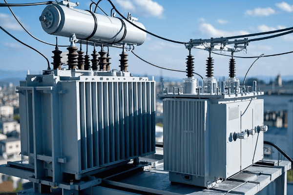
Step up and step down transformers are essential components in power systems. Step up transformers increase voltage for efficient long-distance transmission, while step down transformers reduce voltage for safe local distribution. Both types work on the principle of electromagnetic induction but serve opposite purposes in the power grid.
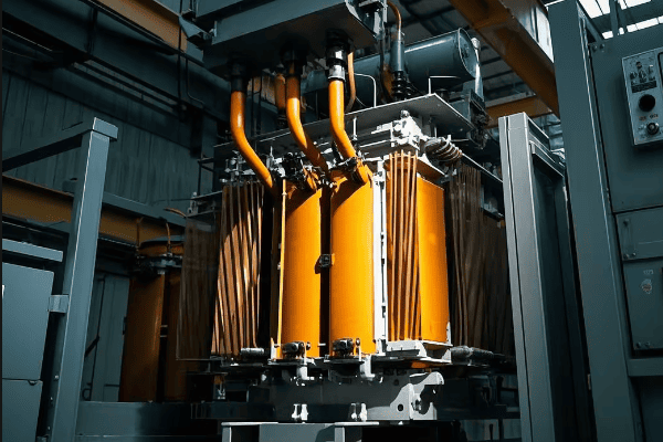
I remember my first encounter with these transformers during a power plant tour. The sheer size and complexity of the step up transformers at the plant’s output left a lasting impression on me.
Core Principles
Both types of transformers operate on the same basic principles:
-
Electromagnetic Induction: This is the key to transformer operation. When an alternating current flows through the primary winding, it creates a changing magnetic field in the transformer’s core. This changing field then induces a voltage in the secondary winding.
-
Winding Ratio: The ratio of turns in the primary winding to the turns in the secondary winding determines whether the transformer steps up or steps down the voltage. This ratio is crucial in determining the transformer’s function.
-
Power Conservation: In an ideal transformer, the power input equals the power output. In reality, there are small losses due to factors like core losses and copper losses, but modern transformers can achieve efficiencies over 99%.
Key Components
All transformers share these basic components:
- Primary Winding: This is the input side of the transformer, connected to the power source.
- Secondary Winding: This is the output side of the transformer.
- Core: Typically made of laminated steel sheets, the core provides a path for the magnetic flux.
- Insulation: Various materials like oil, paper, or epoxy resin are used to insulate the windings and core.
Comparison Table: Step Up vs. Step Down Transformers
| Aspect | Step Up Transformer | Step Down Transformer |
|---|---|---|
| Primary Winding | Fewer turns | More turns |
| Secondary Winding | More turns | Fewer turns |
| Voltage | Increases | Decreases |
| Current | Decreases | Increases |
| Typical Use | Power generation output | Local power distribution |
Understanding these basics is crucial for anyone working with electrical systems. In my career, I’ve found that a solid grasp of these fundamentals is essential for making informed decisions about transformer selection and implementation.
Key Differences: Step Up vs. Step Down Transformers Compared?
Ever wondered why we need different types of transformers? The key lies in their unique characteristics and roles in the power system.
Step up and step down transformers differ primarily in their winding ratios and applications. Step up transformers have more secondary windings to increase voltage, while step down transformers have fewer secondary windings to reduce voltage. These differences make them suitable for distinct stages of power transmission and distribution.
Early in my career, I worked on a project that required both types of transformers. The challenge of integrating them into a single system taught me the importance of understanding their unique characteristics.
Winding Configuration
The main difference lies in the winding setup:
-
Step Up Transformers:
- Primary (input) winding: Fewer turns
- Secondary (output) winding: More turns
- Result: Voltage increases, current decreases
-
Step Down Transformers:
- Primary (input) winding: More turns
- Secondary (output) winding: Fewer turns
- Result: Voltage decreases, current increases
Voltage and Current Relationships
Understanding these relationships is crucial:
-
Step Up Transformers:
- Voltage Out > Voltage In
- Current Out < Current In
- Example: 11kV input might be stepped up to 132kV for transmission
-
Step Down Transformers:
- Voltage Out < Voltage In
- Current Out > Current In
- Example: 33kV input might be stepped down to 415V for industrial use
Application Areas
The choice between step up and step down transformers depends on the specific needs of the power system:
-
Step Up Transformers:
- Power Generation: Increasing voltage from generators (typically 11-25kV) to transmission levels (132-765kV)
- Renewable Energy: Boosting voltage from solar farms or wind turbines to grid-compatible levels
- Industrial Processes: Some specialized industrial applications require higher voltages
-
Step Down Transformers:
- Substations: Reducing transmission voltages (132-765kV) to distribution levels (11-33kV)
- Residential Areas: Further stepping down voltage from distribution levels to household use (120-240V)
- Industrial Equipment: Providing appropriate voltage levels for various machinery and processes
Comparison Table: Detailed Differences
| Characteristic | Step Up Transformer | Step Down Transformer |
|---|---|---|
| Winding Ratio | Secondary > Primary | Primary > Secondary |
| Voltage Change | Increases | Decreases |
| Current Change | Decreases | Increases |
| Typical Input Voltage | 11-25 kV | 33-765 kV |
| Typical Output Voltage | 100-765 kV | 415V-33 kV |
| Core Size | Larger | Smaller |
| Insulation Requirements | Higher | Lower |
| Cooling Needs | More intensive | Less intensive |
| Typical Locations | Power plants, Wind farms | Substations, Neighborhoods |
| Cost | Generally higher | Generally lower |
Understanding these differences is essential for proper transformer selection. In my experience, choosing the wrong type can lead to inefficiencies, safety hazards, and costly mistakes. Always consider the specific requirements of your power system when making this decision.
Application Areas: Where to Use Each Type of Transformer?
Have you ever wondered why different parts of the power grid use different transformers? The answer lies in their specific applications and the unique challenges they address.
Step up transformers are primarily used in power generation and long-distance transmission, increasing voltage to minimize power losses over large distances. Step down transformers are used in distribution networks, industrial settings, and residential areas, reducing voltage to safe and usable levels for end consumers.
I once worked on a project to upgrade a city’s power infrastructure. The strategic placement of both step up and step down transformers throughout the network was crucial for efficient power delivery from the plant to individual homes.
Power Generation and Transmission
Step Up Transformers dominate this area:
-
Power Plants:
- Function: Increase generator output voltage (e.g., 20 kV to 400 kV)
- Why: To reduce transmission losses over long distances
- Example: A 1000 MW coal-fired power plant might use step up transformers to boost voltage from 22 kV to 765 kV for ultra-high voltage transmission
-
Renewable Energy Sources:
- Function: Boost voltage from wind turbines or solar farms
- Why: To match grid voltage levels and enable efficient integration
- Example: A large offshore wind farm might use step up transformers to increase voltage from 33 kV to 220 kV for subsea transmission
-
Transmission Substations:
- Function: Further increase voltage for ultra-long-distance transmission
- Why: To minimize losses in cross-country or international power grids
- Example: A major interconnection point might use step up transformers to boost voltage from 400 kV to 1000 kV for ultra-high voltage direct current (UHVDC) transmission
Power Distribution
Step Down Transformers are key in this sector:
-
Primary Substations:
- Function: Reduce transmission voltages to distribution levels (e.g., 400 kV to 33 kV)
- Why: To prepare power for regional distribution
- Example: A city’s main substation might use step down transformers to reduce 400 kV transmission voltage to 110 kV for urban distribution
-
Secondary Substations:
- Function: Further step down voltage for local distribution (e.g., 33 kV to 11 kV)
- Why: To prepare power for neighborhood-level distribution
- Example: A local substation might use step down transformers to reduce 33 kV to 11 kV for a residential area
-
Pole-mounted Transformers:
- Function: Final voltage reduction for residential use (e.g., 11 kV to 240/120 V)
- Why: To provide safe, usable voltage for households
- Example: A transformer on a utility pole might step down 11 kV to 240/120 V for a group of homes
Industrial Applications
Both types find use in industrial settings:
-
Step Up Transformers:
- Large motors and heavy machinery: Some industrial processes require higher voltages
- Arc furnaces in steel production: These often need voltages stepped up from distribution levels
- Specialized high-voltage processes: Such as in particle accelerators or certain chemical processes
-
Step Down Transformers:
- Factory power distribution: Stepping down incoming high voltage to usable levels for various equipment
- Welding equipment: Providing appropriate voltage levels for welding processes
- Lighting and HVAC systems: Ensuring safe voltage levels for building systems
Commercial and Residential Use
Primarily the domain of Step Down Transformers:
- Office Buildings: Power distribution for lighting, elevators, and HVAC
- Shopping Centers: Ensuring appropriate voltage for various stores and common areas
- Homes: Providing safe voltage levels for household appliances and electronics
Application Comparison Table
| Application | Transformer Type | Typical Input | Typical Output | Key Consideration |
|---|---|---|---|---|
| Power Plant Output | Step Up | 20 kV | 400 kV | Efficiency for long-distance transmission |
| Transmission Substation | Step Up | 400 kV | 765 kV | Ultra-high voltage capability |
| Primary Distribution | Step Down | 400 kV | 33 kV | Reliability and load management |
| Secondary Distribution | Step Down | 33 kV | 11 kV | Urban planning and load distribution |
| Residential Supply | Step Down | 11 kV | 240/120 V | Safety and consistent supply |
| Large Industrial Motor | Step Up | 11 kV | 33 kV | Specific voltage requirements of equipment |
| Office Building | Step Down | 11 kV | 480/277 V | Energy efficiency and power quality |
Understanding these application areas is crucial for electrical engineers and system designers. In my experience, recognizing the specific needs of each part of the power system is key to selecting the right transformer for optimal performance and efficiency.
Performance Factors: Efficiency and Power Handling Capabilities?
When it comes to transformers, efficiency isn’t just a buzzword—it’s a critical factor that can make or break your power system’s performance. But how do we measure and compare transformer efficiency?
Transformer efficiency is typically very high, often exceeding 98%. However, even small improvements in efficiency can lead to significant energy savings over time. Power handling capability, measured in kVA or MVA, determines the maximum load a transformer can handle safely.
I once worked on a project where upgrading to a higher efficiency transformer saved a manufacturing plant over $100,000 in energy costs annually. The initial investment was higher, but the ROI was achieved in less than two years.
Efficiency Considerations
-
Core Losses:
- Also known as iron losses or no-load losses
- Caused by the alternating magnetic field in the core
- Minimized by using high-quality core materials like grain-oriented silicon steel
-
Copper Losses:
- Also called winding losses or load losses
- Caused by resistance in the transformer windings
- Reduced by using larger conductor cross-sections and advanced winding techniques
-
Efficiency Calculation:
Efficiency (%) = (Output Power / Input Power) × 100
= [Output Power / (Output Power + Core Losses + Copper Losses)] × 100 -
Efficiency Standards:
- Different regions have different efficiency standards for transformers
- For example, in the U.S., the Department of Energy (DOE) sets minimum efficiency standards
Power Handling Capability
-
kVA Rating:
- Kilovolt-Ampere rating indicates the transformer’s capacity
- For example, a 1000 kVA transformer can handle 1000 kW at unity power factor
-
Overload Capacity:
- Transformers can handle short-term overloads, but at the cost of increased heat and potential lifespan reduction
- Typical overload capacities range from 10% to 50% for short durations
-
Temperature Rise:
- Directly related to power handling
- Standard temperature rise ratings are 55°C, 80°C, and 115°C
- Higher temperature rise allows for more compact design but may reduce lifespan
Comparison: Step Up vs. Step Down Performance
| Factor | Step Up Transformer | Step Down Transformer |
|---|---|---|
| Typical Efficiency | 98.5% – 99.5% | 97% – 99% |
| Core Losses | Generally higher due to higher flux densities | Lower due to lower operating voltages |
| Copper Losses | Can be significant due to higher currents in primary | Generally lower due to lower currents in secondary |
| Cooling Requirements | More intensive, often oil-cooled | Less intensive, can be air-cooled for smaller units |
| Overload Capacity | Limited due to high voltage stress | Generally better due to lower voltage stress |
| Size and Weight | Larger and heavier for same kVA rating | Smaller and lighter for same kVA rating |
When selecting a transformer, don’t just look at the initial cost. Consider the Total Cost of Ownership (TCO), including energy losses over the transformer’s lifetime. A more efficient transformer might have a higher upfront cost but can lead to significant savings in the long run.
Understanding these performance factors is crucial for making informed decisions about transformer selection and operation. In my years of experience, I’ve found that carefully considering these factors can lead to significant improvements in system efficiency and reliability.
Design Considerations: Core Components and Construction?
The design of a transformer is a delicate balance between efficiency, cost, and reliability. But what are the key components that make up a transformer, and how do they affect its performance?
Transformer design involves careful selection of core materials, winding configurations, and insulation systems. These choices significantly affect the transformer’s efficiency, power handling capacity, and lifespan. Advanced designs can improve performance but often come with higher initial costs.
I once consulted on a project where changing the core material from traditional silicon steel to amorphous metal reduced core losses by 70%. The initial cost was higher, but the energy savings over the transformer’s lifespan more than justified the investment.
Core Design
-
Material Selection:
- Silicon Steel: Most common, balance of cost and performance
- Amorphous Metal: Higher efficiency but more expensive
- Nanocrystalline Materials: Emerging technology, very high efficiency
-
Lamination Thickness:
- Thinner laminations reduce eddy current losses
- Typical thicknesses range from 0.23mm to 0.30mm
-
Core Shape:
- Shell Type: Windings surrounded by core, good for high currents
- Core Type: Core surrounded by windings, more common in distribution transformers
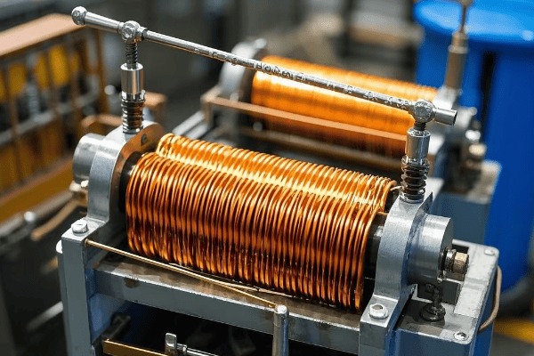
Winding Design
-
Conductor Material:
- Copper: Higher conductivity, but more expensive
- Aluminum: Lighter and cheaper, but lower conductivity
-
Winding Configurations: – Disc Windings: Good for high voltage applications
- Helical Windings: Suitable for high current, low voltage applications
- Layer Windings: Common in distribution transformers
-
Insulation:
- Paper-Oil Insulation: Traditional method, good dielectric strength
- Epoxy Resin: Used in dry-type transformers, good for indoor applications
Cooling Systems
-
Oil-Immersed Transformers:
- ONAN (Oil Natural Air Natural): For smaller units
- ONAF (Oil Natural Air Forced): Fans added for better cooling
- OFAF (Oil Forced Air Forced): Pumps and fans for large units
-
Dry-Type Transformers:
- AN (Air Natural): Relies on natural air circulation
- AF (Air Forced): Uses fans for forced air cooling
Design Comparison: Step Up vs. Step Down Transformers
| Aspect | Step Up Transformer | Step Down Transformer |
|---|---|---|
| Core Size | Larger due to higher flux densities | Smaller, more compact design possible |
| Winding Insulation | Higher grade insulation required | Standard insulation often sufficient |
| Cooling System | Often requires more advanced cooling | Simpler cooling systems may suffice |
| Tap Changers | Less common | More common for voltage regulation |
| Surge Protection | More critical due to high voltages | Important but less critical |
When designing or selecting a transformer, consider future load growth. It’s often more cost-effective to slightly oversize a transformer initially than to replace it prematurely due to increased load demands.
The design of a transformer is a complex process that requires balancing multiple factors. In my experience, working closely with manufacturers and understanding your specific needs is key to getting the right design for your application.
Safety Features: Protecting Equipment and Personnel?
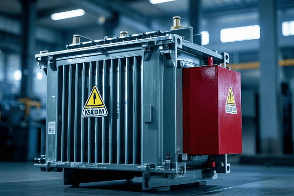
Safety is paramount in transformer design and operation. But what specific features ensure the safety of both equipment and personnel?
Modern transformers incorporate multiple safety features including overcurrent protection, temperature monitoring, and pressure relief devices. These systems work together to prevent catastrophic failures, minimize fire risks, and protect personnel from electrical hazards.
I once investigated a transformer failure where a malfunctioning Buchholz relay prevented a minor issue from escalating into a major disaster. This experience underscored for me the critical importance of robust safety systems in transformer design.
Overcurrent Protection
-
Fuses:
- Used in smaller transformers
- Provide fast response to short circuits
-
Circuit Breakers:
- Used in larger transformers
- Can be remotely operated for quick isolation
-
Differential Relays:
- Compare current entering and leaving the transformer
- Detect internal faults quickly
Temperature Monitoring
-
Oil Temperature Indicators:
- Monitor top oil temperature
- Trigger alarms or cooling systems when temperature exceeds set points
-
Winding Temperature Indicators:
- Estimate winding temperature based on oil temperature and load current
- Critical for preventing insulation breakdown
-
Fiber Optic Sensors:
- Provide direct winding temperature measurement in some modern designs
- Offer more accurate and responsive temperature monitoring
Pressure Relief Devices
-
Pressure Relief Valves:
- Release pressure in case of rapid gas buildup
- Prevent tank rupture in severe fault conditions
-
Buchholz Relay:
- Detects gas accumulation or oil flow in oil-filled transformers
- Provides early warning of developing faults
Safety Feature Comparison: Step Up vs. Step Down Transformers
| Safety Feature | Step Up Transformer | Step Down Transformer |
|---|---|---|
| Insulation Level | Higher voltage class insulation | Standard insulation often sufficient |
| Surge Arresters | Critical due to exposure to lightning strikes | Important but less critical |
| Buchholz Relay | Standard feature | May be omitted in smaller units |
| Fire Suppression | Often includes advanced systems | Basic systems may suffice |
| Physical Barriers | Extensive due to high voltages | Standard safety enclosures |
Regular safety audits and maintenance of protection systems are crucial. Don’t wait for a failure to occur – proactive safety management can prevent costly downtime and potentially save lives.
Understanding and properly maintaining these safety features is crucial for anyone working with or around transformers. In my career, I’ve seen how robust safety systems can prevent minor issues from escalating into major incidents.
Cost Analysis: Initial Investment vs. Long-term Operation?
When it comes to transformers, the upfront cost is just the tip of the iceberg. But how do you balance initial investment with long-term operational costs?
The total cost of ownership for a transformer includes the initial purchase price, installation costs, energy losses over its lifetime, and maintenance expenses. While more efficient transformers often have higher upfront costs, they can lead to significant savings in energy costs over time.
I once advised a client to invest in a higher-efficiency transformer despite its 20% higher initial cost. Over a 15-year period, the energy savings amounted to more than three times the extra initial investment.
Initial Costs
-
Purchase Price:
- Varies based on size, type, and efficiency rating
- Higher efficiency models typically cost more upfront
-
Installation Costs:
- Include transportation, site preparation, and commissioning
- Can vary significantly based on location and transformer size
-
Auxiliary Equipment:
- Cooling systems, monitoring devices, and protection equipment
- Often overlooked but can add substantially to initial costs
Operational Costs
-
Energy Losses:
- No-load losses (core losses) occur 24/7, even when the transformer is idle
- Load losses vary with the transformer’s load
-
Maintenance:
- Routine inspections, oil testing, and part replacements
- More complex designs may require specialized maintenance
-
Reliability:
- Downtime costs due to failures can be substantial
- Higher quality transformers often have better reliability
Cost Comparison: Step Up vs. Step Down Transformers
| Cost Factor | Step Up Transformer | Step Down Transformer |
|---|---|---|
| Initial Cost | Generally higher | Lower for comparable kVA rating |
| Installation | More complex, higher cost | Simpler, lower cost |
| Energy Losses | Higher due to higher voltages | Lower for comparable kVA rating |
| Maintenance | More intensive, higher cost | Less intensive, lower cost |
| Lifespan | 25-40 years | 20-35 years |
When evaluating transformer options, use the Total Cost of Ownership (TCO) approach. Calculate the lifetime energy costs based on your local electricity rates and expected load profile. Often, the most cost-effective choice is not the one with the lowest purchase price.
In my experience, a thorough cost analysis that considers both initial and long-term costs is essential for making a sound investment in transformer technology. It’s not just about buying a transformer; it’s about investing in your power system’s future.
Maintenance Requirements: Ensuring Longevity and Reliability?
Proper maintenance is crucial for transformer longevity and reliability. But what does a comprehensive maintenance program look like?
A well-designed maintenance program for transformers includes regular inspections, oil testing, and preventive repairs. Proactive maintenance can extend a transformer’s lifespan, improve reliability, and prevent costly unplanned outages.
I once worked with a utility company that implemented a rigorous maintenance program. They saw a 40% reduction in transformer-related outages over a five-year period, significantly improving their service reliability.
Routine Inspections
-
Visual Checks:
- Look for oil leaks, rust, or damage to bushings
- Check gauges and indicators for abnormal readings
-
Thermal Imaging:
- Detect hot spots that may indicate problems
- Typically done annually or semi-annually
-
Acoustic Emission Testing:
- Listen for partial discharges or other abnormal sounds
- Can detect developing faults before they become serious
Oil Testing and Management
-
Dissolved Gas Analysis (DGA):
- Detects gases dissolved in transformer oil
- Can indicate various types of faults
-
Oil Quality Tests:
- Check for moisture content, acidity, and dielectric strength
- Crucial for maintaining insulation properties
-
Oil Filtering or Replacement:
- Remove contaminants or replace degraded oil
- Frequency depends on oil condition and transformer age
Electrical Testing
-
Insulation Resistance Tests:
- Measure the resistance between windings and ground
- Helps detect insulation degradation
-
Power Factor Tests:
- Assess the overall condition of the insulation system
- Typically performed annually
-
Turns Ratio Tests:
- Verify the transformer’s turns ratio
- Can detect shorted turns or other winding issues
Maintenance Comparison: Step Up vs. Step Down Transformers
| Maintenance Aspect | Step Up Transformer | Step Down Transformer |
|---|---|---|
| Frequency of Inspections | More frequent due to criticality | Less frequent for smaller units |
| Oil Testing | More comprehensive | Basic tests may suffice |
| Electrical Testing | More extensive | Less extensive for smaller units |
| Cooling System Maintenance | More complex, critical | Simpler, less critical for air-cooled units |
| Cost of Maintenance | Generally higher | Lower for comparable size |
Develop a maintenance schedule based on the transformer’s size, type, and criticality. For critical transformers, consider online monitoring systems that provide real-time data on key parameters.
In my years of experience, I’ve found that a well-maintained transformer not only lasts longer but also operates more efficiently and reliably. The cost of maintenance is always less than the cost of unexpected failures and outages.
Conclusion
Choosing between step up and step down transformers requires careful consideration of various factors including application, efficiency, design, safety, cost, and maintenance. Each type has its unique strengths and is suited for specific roles in the power system.
