Are you struggling to choose the right 3 phase distribution transformer for your project? You’re not alone. Many engineers and project managers find themselves overwhelmed by the technical specifications and diverse options available. But what if you had a clear, step-by-step guide to ensure you select the perfect transformer for your specific needs?
To select the right 3-phase distribution transformer, match your system voltage, load kVA requirements, and cooling type (AN, AF, or oil-immersed). This guide helps engineers and buyers choose the optimal transformer for industrial, commercial, or utility projects with minimal energy loss and maximum reliability.
In this comprehensive guide, I’ll walk you through the essential steps to select the ideal 3 phase distribution transformer for your project. Whether you’re working on an industrial facility, a commercial building, or a utility-scale installation, this article will provide you with the knowledge to make an informed decision that balances performance, efficiency, and cost.
What Is a 3 Phase Distribution Transformer?
Have you ever wondered how electricity from power plants is transformed into usable power for buildings and industries? This is where 3 phase distribution transformers come into play. But what exactly are they, and why are they so crucial in our power systems?
A 3 phase distribution transformer is an electrical device that converts high-voltage electricity from power stations into lower voltage suitable for end-user consumption. It handles three alternating currents, phase-shifted by 120 degrees, providing more efficient power transmission and distribution for larger loads in industrial, commercial, and residential applications.

Understanding 3 Phase Distribution Transformers
Let’s break down the key aspects of these transformers:
- Basic Structure and Components
- Function in Power Distribution
- Advantages of 3 Phase Systems
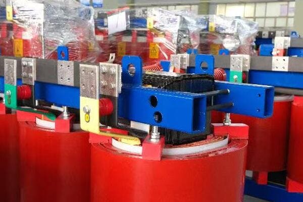
Basic Structure and Components
A 3 phase distribution transformer typically consists of:
- Three sets of primary and secondary windings
- A magnetic core (usually made of silicon steel)
- Insulation materials (oil or dry-type)
- Cooling system (natural air, forced air, or oil)
I remember my first encounter with a 3 phase transformer during an industrial plant upgrade. The complexity of its internal structure was fascinating, especially how the three phases were intricately wound around the core.
Function in Power Distribution
These transformers play a crucial role in power systems:
- Step down high voltage from transmission lines to usable levels
- Maintain phase relationships between primary and secondary sides
- Provide isolation between high voltage and low voltage systems
During a recent project for a shopping mall, the 3 phase transformer was the key component in efficiently distributing power across various loads, from HVAC systems to lighting circuits.
Advantages of 3 Phase Systems
3 phase transformers offer several benefits over single-phase systems:
- More efficient power transmission
- Better suited for large, balanced loads
- Smoother power delivery with less pulsation
- Ideal for industrial motors and heavy equipment
Here’s a quick comparison table:
| Aspect | 3 Phase Transformer | Single Phase Transformer |
|---|---|---|
| Power Capacity | Higher for same size | Lower for same size |
| Efficiency | Generally higher | Lower for large loads |
| Application | Industrial, commercial | Residential, small commercial |
| Load Balancing | Better | Limited |
Understanding these basics is crucial for proper transformer selection. In my experience, a clear grasp of what a 3 phase distribution transformer is and how it functions forms the foundation for making informed decisions in the selection process.
As we move forward to discuss why choosing the right transformer matters, keep in mind that these devices are not just components in a power system – they are critical links that ensure efficient, reliable, and safe power distribution in our modern world.
Why Choosing the Right Transformer Matters?
Have you ever considered the long-term implications of selecting the wrong transformer for your project? Many professionals underestimate the impact of this decision, but the consequences can be significant. So, why is choosing the right transformer so crucial, and how does it affect your project’s success?
Selecting the right 3 phase distribution transformer is critical for system efficiency, reliability, and cost-effectiveness. An appropriately sized and specified transformer ensures optimal load handling, minimizes energy losses, reduces the risk of failures, and lowers long-term operational costs. Incorrect selection can lead to poor performance, increased maintenance, and potential safety hazards.
The Impact of Proper Transformer Selection
Let’s explore the key reasons why choosing the right transformer is so important:
- System Efficiency and Energy Savings
- Reliability and Operational Continuity
- Safety and Compliance
- Long-term Cost Implications
System Efficiency and Energy Savings
Proper transformer selection directly affects energy efficiency:
- Correctly sized transformers operate at peak efficiency
- Oversized transformers lead to unnecessary core losses
- Undersized transformers result in increased copper losses and overheating
I once worked on a project where replacing an oversized transformer with a properly rated one led to a 15% reduction in energy losses, translating to significant cost savings for the client over time.
Reliability and Operational Continuity
The right transformer ensures reliable operation:
- Matches load profile to prevent overloading
- Reduces risk of unexpected failures and downtime
- Ensures proper voltage regulation under varying load conditions
During a recent industrial facility upgrade, choosing a transformer with the correct kVA rating and impedance helped maintain stable voltage levels across various production lines, significantly improving overall operational reliability.
Safety and Compliance
Proper selection is crucial for safety:
- Ensures compliance with local electrical codes and standards
- Reduces risk of overheating and fire hazards
- Provides appropriate short-circuit protection
I recall a case where an undersized transformer in a commercial building led to frequent tripping and posed a fire risk. Replacing it with a correctly specified unit resolved these safety concerns and brought the installation into compliance.
Long-term Cost Implications
The right choice impacts long-term costs:
- Reduces energy losses and operational expenses
- Minimizes maintenance and replacement costs
- Extends the lifespan of the transformer and connected equipment
Here’s a comparison of cost factors:
| Factor | Proper Selection | Improper Selection |
|---|---|---|
| Energy Efficiency | High | Low to Medium |
| Maintenance Costs | Low | Potentially High |
| Lifespan | Extended | Potentially Shortened |
| Operational Reliability | High | Variable to Low |
Key considerations for transformer selection:
- Accurate load calculation and future growth estimation
- Understanding of the specific application requirements
- Consideration of environmental factors and installation location
- Evaluation of total cost of ownership, not just initial purchase price
- Compliance with relevant standards and regulations
In my experience, the importance of choosing the right transformer cannot be overstated. I’ve seen projects where cutting corners on transformer selection led to increased operational costs, reliability issues, and even safety hazards. Conversely, projects that invested time and resources in proper selection reaped benefits in terms of efficiency, reliability, and long-term cost savings.
As we move forward to discuss the specific steps in selecting a 3 phase distribution transformer, keep in mind that each decision in this process contributes to the overall success and efficiency of your power distribution system. The right choice not only ensures optimal performance but also provides peace of mind knowing that your system is safe, efficient, and built to last.
Step 1: Determine System Voltage Requirements?
Are you unsure about how to determine the correct voltage requirements for your 3 phase distribution transformer? This crucial first step can be confusing, especially with varying standards across different regions. But how can you ensure you’re selecting the right voltage levels for your specific application?
Determining system voltage requirements involves identifying both primary and secondary voltage levels. Common primary voltages include 11kV, 33kV, or 69kV, while secondary voltages are typically 400V, 480V, or 600V. Consider regional standards (IEC or ANSI), voltage drop, and future expansion needs. Accurate voltage selection ensures compatibility with existing infrastructure and optimal transformer performance.
Key Factors in Determining Voltage Requirements
Let’s break down the process of determining voltage requirements:
- Understanding Primary and Secondary Voltages
- Regional Standards and Variations
- Voltage Drop Considerations
- Future Expansion Planning
Understanding Primary and Secondary Voltages
Primary (input) and secondary (output) voltages are crucial:
- Primary voltage: Typically the utility supply voltage
- Secondary voltage: The required voltage for your application
I once worked on a project where misunderstanding the primary voltage led to ordering the wrong transformer. Always double-check with your local utility provider to confirm the supply voltage.
Regional Standards and Variations
Voltage standards can vary by region:
- IEC standards (common in Europe and Asia)
- ANSI standards (prevalent in North America)
- Local utility requirements
During an international project, I learned the importance of understanding local standards. What was standard in one country was uncommon in another, affecting our entire transformer specification.
Voltage Drop Considerations
Account for voltage drop in your system:
- Calculate expected voltage drop from transformer to load
- Consider using transformer taps for fine-tuning output voltage
In a recent industrial installation, we had to factor in a significant voltage drop due to long cable runs. Selecting a transformer with appropriate taps allowed us to compensate for this drop effectively.
Future Expansion Planning
Plan for potential future needs:
- Consider higher primary voltage for future power increases
- Allow for secondary voltage flexibility if load types might change
Here’s a quick reference table for common voltage levels:
| Application | Primary Voltage | Secondary Voltage | Common in |
|---|---|---|---|
| Industrial | 33kV, 11kV | 400V, 480V | Global |
| Commercial | 11kV, 13.8kV | 400V, 208V | Varies |
| Utility | 69kV, 138kV | 11kV, 33kV | Utility-specific |
Key considerations for determining voltage requirements:
- Consult with local utility providers for primary voltage information
- Understand the voltage needs of your end-use equipment
- Consider regional standards and practices
- Account for voltage drop in your distribution system
- Plan for potential future voltage needs or system expansions
In my experience, accurately determining voltage requirements is fundamental to proper transformer selection. I’ve seen projects where overlooking seemingly minor voltage details led to significant issues down the line, from equipment incompatibility to efficiency losses.
Remember, the voltage selection process is not just about meeting current needs; it’s about ensuring your power distribution system remains flexible and efficient for years to come. By carefully considering these factors, you can make an informed decision that will serve your project well into the future.
As we move on to discuss load calculation and kVA rating, keep in mind that these voltage considerations will play a crucial role in determining the overall specifications of your 3 phase distribution transformer.
Step 2: Calculate Load and kVA Rating?
Are you finding it challenging to accurately determine the required kVA rating for your 3 phase distribution transformer? This step is often where many engineers and project managers stumble, leading to over or undersized transformers. But how can you ensure you’re calculating the load correctly and selecting the optimal kVA rating?
Calculating the proper kVA rating involves summing all connected loads, considering diversity factors, and planning for future expansion. Start by listing all equipment power ratings, apply appropriate demand factors, and add a safety margin (typically 15-25%). For three-phase loads, use the formula: kVA = (V × I × √3) / 1000. Always round up to the next standard kVA size to ensure adequate capacity.
Steps to Calculate Load and Determine kVA Rating
Let’s break down the process into manageable steps:
- Identify All Connected Loads
- Apply Diversity and Demand Factors
- Calculate Total kVA Requirement
- Consider Future Expansion
- Select Standard kVA Rating
Identify All Connected Loads
Start by listing all equipment that will be powered:
- Motors, HVAC systems, lighting, office equipment, etc.
- Note both the running and starting power requirements
I once worked on a factory project where overlooking the starting current of large motors led to an undersized transformer. Always consider both continuous and peak loads.
Apply Diversity and Demand Factors
Not all equipment operates simultaneously or at full capacity:
- Use diversity factors to account for non-coincident operation
- Apply demand factors based on historical usage patterns
During a recent commercial building project, applying appropriate diversity factors allowed us to optimize the transformer size, resulting in significant cost savings without compromising reliability.
Calculate Total kVA Requirement
Use the following formula for three-phase loads:
kVA = (V × I × √3) / 1000
For single-phase loads on a three-phase system:
kVA = (V × I) / 1000 (per phase)
Sum up all the calculated kVA values.
Consider Future Expansion
Always plan for potential growth:
- Add a safety margin of 15-25% to your calculated load
- Consider known future expansions or equipment additions
In an industrial park project, we factored in a 20% capacity increase for future tenants. This foresight proved invaluable when new businesses moved in, avoiding the need for costly upgrades.
Select Standard kVA Rating
Round up to the next standard kVA size:
- Common ratings: 75, 112.5, 150, 225, 300, 500, 750, 1000, 1500, 2000 kVA
Here’s a quick reference table for load types and their typical demand factors:
| Load Type | Typical Demand Factor |
|---|---|
| Lighting | 100% |
| HVAC | 80-90% |
| Office Equipment | 50-70% |
| Industrial Motors | 70-80% |
| Welding Equipment | 30-50% |
Key considerations for load calculation and kVA rating:
- Be comprehensive in identifying all potential loads
- Use realistic diversity and demand factors based on actual usage patterns
- Don’t forget to account for power factor in your calculations
- Consider both normal operating conditions and peak demand scenarios
- Always include a safety margin for unexpected load increases
In my experience, accurate load calculation is as much an art as it is a science. I’ve seen projects where overly conservative estimates led to unnecessarily large and expensive transformers, while underestimation resulted in overheating and premature failure.
Remember, the goal is not just to meet current needs but to provide a reliable and efficient power supply for the foreseeable future. By carefully considering all factors and applying sound engineering principles, you can select a kVA rating that balances capacity, efficiency, and cost-effectiveness.
As we move on to discuss cooling methods, keep in mind that the kVA rating you’ve calculated will play a crucial role in determining the appropriate cooling system for your transformer.
Step 3: Choose the Right Cooling Method (AN, AF, Oil)?
Are you confused about which cooling method is best for your 3 phase distribution transformer? With options like air natural (AN), air forced (AF), and oil-immersed cooling, making the right choice can be daunting. But how do you determine which cooling method will ensure optimal performance and longevity for your specific application?
Choosing the right cooling method depends on factors like transformer size, environment, and application. Air Natural (AN) cooling suits smaller, indoor transformers. Air Forced (AF) is ideal for larger dry-type units or where space is limited. Oil-immersed cooling offers superior heat dissipation for high-capacity transformers and harsh environments. Consider factors like maintenance needs, fire safety, and installation location when selecting.
Understanding Transformer Cooling Methods
Let’s explore the three main cooling methods:
- Air Natural (AN) Cooling
- Air Forced (AF) Cooling
- Oil-Immersed Cooling
- Selecting the Right Method
Air Natural (AN) Cooling
AN cooling relies on natural air circulation:
- Suitable for smaller transformers (typically up to 3 MVA)
- Ideal for indoor installations with good ventilation
- Low maintenance and noise levels
I once worked on a commercial building project where AN cooling was perfect for the basement transformer room. Its quiet operation and minimal maintenance needs were ideal for the space.
Air Forced (AF) Cooling
AF cooling uses fans to enhance air circulation:
- Suitable for larger dry-type transformers
- Allows for higher capacity in a compact size
- Requires regular maintenance of fans and filters
During an industrial facility upgrade, we opted for AF cooling for a 5 MVA transformer. The forced air allowed for a more compact installation in the limited space available.
Oil-Immersed Cooling
Oil-immersed cooling uses insulating oil for heat dissipation:
- Ideal for high-capacity transformers (typically above 5 MVA)
- Excellent for outdoor installations and harsh environments
- Provides superior insulation and cooling efficiency
I recall a utility-scale project where oil-immersed cooling was crucial. The transformer’s high capacity and outdoor location made oil cooling the most effective and reliable choice.
Selecting the Right Method
Consider these factors when choosing a cooling method:
- Transformer capacity and size
- Installation environment (indoor/outdoor, temperature extremes)
- Maintenance capabilities and requirements
- Fire safety considerations
- Noise limitations
- Future load growth potential
Here’s a comparison table of cooling methods:
| Cooling Method | Typical Capacity | Best For | Maintenance Needs |
|---|---|---|---|
| Air Natural (AN) | Up to 3 MVA | Indoor, quiet areas | Low |
| Air Forced (AF) | 3-10 MVA | Space-constrained areas | Moderate |
| Oil-Immersed | 5 MVA and above | Outdoor, harsh environments | High (but infrequent) |
Key considerations for choosing the right cooling method:
- Match the cooling method to your calculated kVA rating
- Consider the installation environment and space constraints
- Evaluate long-term maintenance requirements and costs
- Assess fire safety regulations, especially for indoor installations
- Factor in noise limitations, particularly in urban or sensitive areas
In my experience, the choice of cooling method can significantly impact a transformer’s performance and lifespan. I’ve seen projects where an inappropriate cooling choice led to premature transformer failure, while the right choice ensured years of reliable operation.
For instance, in a data center project, we initially considered oil-immersed cooling for its efficiency. However, after evaluating fire safety concerns and the indoor installation requirements, we opted for a high-capacity AF-cooled transformer. This decision balanced cooling efficiency with the stringent safety needs of the data center environment.
Remember, the cooling method you choose isn’t just about meeting current needs; it’s about ensuring your transformer operates efficiently and reliably throughout its lifespan. By carefully considering all factors and aligning them with your specific project requirements, you can select a cooling method that optimizes performance, safety, and long-term cost-effectiveness.
As we move forward to discuss typical use cases by industry, keep in mind how these cooling methods align with different applications and environments. This understanding will help you make more informed decisions in your transformer selection process.
Comparison Table: Typical Use Cases by Industry?
Are you wondering how different industries typically approach transformer selection? Understanding common practices across various sectors can provide valuable insights for your own project. But how do transformer specifications typically vary across industrial, commercial, and utility applications?
Different industries have distinct transformer needs based on their power requirements, environmental conditions, and operational demands. Industrial settings often require high-capacity, oil-cooled transformers for heavy loads. Commercial applications typically use dry-type transformers for safety and maintenance ease. Utilities often employ large, oil-immersed transformers for grid-level distribution. Understanding these patterns helps in making informed decisions for specific projects.
Industry-Specific Transformer Use Cases
Let’s explore typical transformer configurations across different sectors:
- Industrial Applications
- Commercial and Institutional Settings
- Utility and Power Distribution
- Specialized Industries
Industrial Applications
Industrial settings often have unique power needs:
- High capacity requirements for heavy machinery
- Need for reliability in continuous operation
- Often prefer oil-cooled transformers for efficiency
During a steel mill project, we implemented a 10 MVA oil-cooled transformer to handle the enormous power demands of electric arc furnaces. The transformer’s ability to manage high loads and withstand harsh conditions was crucial.
Commercial and Institutional Settings
Commercial buildings have different priorities:
- Focus on safety and low maintenance
- Often use dry-type transformers for indoor installations
- Emphasis on energy efficiency and quiet operation
In a recent hospital renovation, we chose AF-cooled dry-type transformers. Their fire-resistant properties and low noise levels were perfect for the sensitive healthcare environment.
Utility and Power Distribution
Utility-scale applications have specific requirements:
- Very high capacity for grid-level distribution
- Outdoor installation capabilities
- Often use large oil-immersed transformers
I worked on a substation upgrade where we installed a 50 MVA oil-immersed transformer. Its ability to handle high voltages and provide efficient power distribution was essential for the regional grid.
Specialized Industries
Some industries have unique transformer needs:
- Data Centers: Emphasis on reliability and efficiency
- Renewable Energy: Need for transformers that can handle variable loads
- Marine Applications: Compact, corrosion-resistant designs
Here’s a comparison table of typical transformer specifications by industry:
| Industry | Typical Capacity | Preferred Cooling | Common Features |
|---|---|---|---|
| Heavy Industrial | 5-20 MVA | Oil-immersed | High short-circuit strength |
| Commercial Buildings | 500 kVA – 2.5 MVA | Dry-type (AN/AF) | Low noise, fire-resistant |
| Utility Distribution | 10-100 MVA | Oil-immersed | On-load tap changers |
| Data Centers | 1-5 MVA | Dry-type (AF) | High efficiency, redundancy |
| Renewable Energy | Variable | Dry-type/Oil | Ability to handle fluctuating loads |
Key considerations for industry-specific transformer selection:
- Understand the unique power demands of your industry
- Consider environmental factors specific to your application
- Evaluate safety requirements, especially in commercial or public spaces
- Factor in long-term operational costs and efficiency
- Consider future expansion needs typical in your industry
In my experience, recognizing industry trends in transformer use can provide valuable guidance, but it’s crucial to assess each project individually. I recall a manufacturing facility project where, contrary to the usual practice of using oil-cooled transformers, we opted for a large dry-type unit due to specific fire safety regulations and the client’s maintenance preferences.
Remember, while industry norms can offer a starting point, the best transformer choice always depends on your specific project requirements. By understanding these typical use cases and combining them with your unique needs, you can make a more informed decision that aligns with both industry standards and your particular situation.
As we move on to discuss China’s top brands for 3 phase distribution transformers, keep these industry-specific considerations in mind. They’ll help you appreciate how different manufacturers might cater to various sector needs and how this aligns with your project requirements.
🇨🇳 China’s Top Brands for 3 Phase Distribution Transformers (2025)?
Are you considering Chinese manufacturers for your 3 phase distribution transformer needs? With China’s growing prominence in the global electrical equipment market, understanding the top brands and their specialties is crucial. But how do you navigate the diverse offerings from Chinese manufacturers to find the best fit for your project?
China’s leading 3 phase distribution transformer brands in 2025 include TBEA, ABB (China), Siemens (China), SUNTEN, and Huapeng. These manufacturers offer a range of options from high-efficiency industrial transformers to compact designs for urban applications. Chinese brands are known for competitive pricing, growing technological capabilities, and increasing focus on energy efficiency and smart features.
Analyzing China’s Top Transformer Brands
Let’s explore the strengths and specialties of these leading brands:
- TBEA
- ABB (China)
- Siemens (China)
- SUNTEN
- Huapeng
TBEA
TBEA is known for its comprehensive range of transformers:
- Specializes in high-capacity transformers for industrial and utility use
- Strong presence in Belt and Road Initiative projects
- Focus on energy-efficient designs
I recently worked on a large industrial park project where TBEA’s high-capacity oil-immersed transformers were selected for their reliability and efficiency in handling heavy industrial loads.
ABB (China)
ABB’s Chinese operations offer cutting-edge technology:
- Advanced dry-type transformers for urban applications
- Smart transformer solutions with digital monitoring capabilities
- Strong focus on energy efficiency and environmental sustainability
During a smart city project, we implemented ABB’s smart transformers. Their ability to provide real-time data and optimize power distribution was crucial for the project’s energy management goals.
Siemens (China)
Siemens brings German engineering expertise to the Chinese market:
- High-quality transformers for various applications
- Emphasis on reliability and long-term performance
- Growing focus on green and efficient transformer solutions
In a recent healthcare facility upgrade, Siemens’ low-noise, high-efficiency transformers were the perfect fit, meeting both the technical requirements and the stringent environmental standards of the hospital.
SUNTEN
SUNTEN specializes in compact and efficient designs:
- Known for space-saving transformer solutions
- Strong presence in commercial and light industrial applications
- Growing focus on renewable energy integration
For a urban redevelopment project with severe space constraints, SUNTEN’s compact dry-type transformers provided the perfect solution, offering high performance in a limited footprint.
Huapeng
Huapeng offers cost-effective solutions:
- Wide range of transformers for various applications
- Known for good value-for-money propositions
- Increasing focus on quality and international standards compliance
In a series of small to medium-sized industrial projects, Huapeng’s transformers offered a good balance of performance and affordability, making them an attractive choice for budget-conscious clients.
Here’s a comparison table of these top Chinese brands:
| Brand | Specialty | Best For | Notable Feature |
|---|---|---|---|
| TBEA | High-capacity industrial | Large-scale projects | Belt and Road expertise |
| ABB (China) | Smart transformers | Urban, data-driven applications | Digital integration |
| Siemens (China) | Reliable, efficient designs | Healthcare, sensitive environments | Low noise, high efficiency |
| SUNTEN | Compact designs | Space-constrained urban projects | Space-saving solutions |
| Huapeng | Cost-effective options | Small to medium industries | Value for money |
Key considerations when choosing Chinese transformer brands:
- Evaluate the brand’s expertise in your specific application area
- Consider their compliance with international standards (IEC, ANSI)
- Assess after-sales support and warranty terms, especially for international projects
- Look into their track record in energy efficiency and environmental sustainability
- Consider the brand’s experience in your geographical region or similar markets
In my experience, Chinese transformer manufacturers have made significant strides in quality and technology in recent years. However, it’s crucial to do thorough due diligence. I recall a project where we initially hesitated to use a Chinese brand due to concerns about quality. After a comprehensive review and factory visit, we were impressed by their advanced manufacturing processes and quality control, leading to a successful implementation.
Remember, while these Chinese brands offer competitive options, the best choice depends on your specific project requirements, budget constraints, and long-term operational needs. By carefully considering these factors and aligning them with the strengths of different manufacturers, you can make an informed decision that balances cost-effectiveness with performance and reliability.
As we conclude this guide, keep in mind that the transformer market is dynamic, with continuous advancements in technology and efficiency. Stay informed about the latest developments to ensure you’re always making the best choice for your projects.
Conclusion: Smart Selection Saves Cost and Boosts Reliability
Choosing the right 3 phase distribution transformer is crucial for project success. By carefully considering voltage requirements, accurately calculating load, selecting appropriate cooling methods, and understanding industry-specific needs, you can ensure optimal performance, efficiency, and reliability. Remember, smart selection not only saves costs but also enhances long-term operational reliability.
Remember, at chbeb-ele, we’re not just sharing information – we’re empowering you to be part of the solution in creating a secure, clean, and efficient energy future. Let’s continue this journey together.
Are you struggling to understand the differences between Delta and Wye configurations in 3 phase transformers? You’re not alone. Many engineers and project managers find themselves confused when choosing between these two wiring options. But what if you could easily grasp the pros and cons of each configuration to make informed decisions for your projects?
Delta and Wye are the two main wiring configurations in 3-phase distribution transformers. Delta offers higher phase-to-phase voltage and no neutral, ideal for industrial loads. Wye provides a neutral point and safer grounding, making it suitable for balanced residential or commercial applications.
In this comprehensive guide, I’ll walk you through the ins and outs of Delta and Wye configurations in 3 phase distribution transformers. Whether you’re a seasoned electrical engineer or a project manager looking to expand your knowledge, this article will provide you with the insights you need to understand and apply these crucial wiring configurations effectively.
What Are Delta and Wye Wiring Configurations?
Have you ever wondered why some transformers have three wires while others have four? This is where Delta and Wye configurations come into play. But what exactly are these configurations, and how do they differ in structure?
Delta and Wye are the two primary wiring configurations for 3 phase transformers. In a Delta configuration, windings are connected in a triangle shape with no neutral point. Wye configuration forms a Y-shape with a central neutral point. These configurations affect voltage relationships, grounding options, and load handling capabilities of the transformer.

Understanding Delta and Wye Configurations
Let’s break down the key aspects of these configurations:
- Basic Structure
- Voltage Relationships
- Neutral Point Presence
- Common Applications
Basic Structure
Delta Configuration:
- Three windings connected end-to-end forming a triangle
- No neutral point
- Three-wire system
Wye Configuration:
- Three windings connected at a common point (neutral)
- Four-wire system (including neutral)
I remember my first encounter with these configurations during an industrial plant upgrade. The visual difference in wiring diagrams was striking, and understanding their implications was crucial for the project’s success.
Voltage Relationships
Delta Configuration:
- Line voltage = Phase voltage
- Suitable for high current, low voltage applications
Wye Configuration:
- Line voltage = √3 × Phase voltage
- Offers both high voltage (line-to-line) and low voltage (line-to-neutral) options
During a recent project for a manufacturing facility, choosing the right configuration based on voltage relationships was key to optimizing power distribution efficiency.
Neutral Point Presence
Delta Configuration:
- No neutral point
- Cannot supply single-phase loads efficiently
Wye Configuration:
- Neutral point available
- Can easily supply both three-phase and single-phase loads
The presence of a neutral point in Wye configurations proved invaluable in a mixed-use building project I worked on, allowing for efficient distribution of both three-phase and single-phase power.
Common Applications
Here’s a quick reference table for common applications:
| Configuration | Typical Applications | Key Advantage |
|---|---|---|
| Delta | Industrial motors, Welding equipment | Higher current capacity |
| Wye | Residential power, Office buildings | Versatility in voltage options |
Understanding these basic differences is crucial for proper system design and integration. I once encountered a situation where an incorrectly specified Delta configuration led to grounding issues in a commercial setting. This experience underscored the importance of understanding these configurations in real-world applications.
As we delve deeper into the differences and applications of Delta and Wye configurations, keep in mind that each has its unique strengths and ideal use cases. The choice between them can significantly impact the efficiency, safety, and versatility of your power distribution system.
Key Differences Between Delta and Wye in 3 Phase Transformers?
Are you finding it challenging to distinguish between Delta and Wye configurations in practical scenarios? You’re not alone. Many professionals struggle to identify the key technical differences that make each configuration suitable for specific applications. But what if you had a clear comparison to guide your decision-making process?
Delta and Wye configurations differ in several key aspects. Delta offers higher efficiency for balanced loads and is ideal for high-current applications. Wye provides better voltage stability, easier grounding, and is suitable for both three-phase and single-phase loads. Delta has no neutral point, while Wye offers a neutral for grounding and single-phase power. These differences affect their suitability for various industrial, commercial, and residential applications.

Analyzing Key Differences
Let’s explore the crucial differences between Delta and Wye configurations:
- Voltage and Current Characteristics
- Efficiency and Load Handling
- Grounding and Fault Protection
- Harmonics and Power Quality
Voltage and Current Characteristics
Delta Configuration:
- Higher line current (1.73 times phase current)
- Line voltage equal to phase voltage
- Suitable for high-current, low-voltage applications
Wye Configuration:
- Lower line current
- Line voltage 1.73 times higher than phase voltage
- Offers both high-voltage and low-voltage options
I recall a project where we switched from Wye to Delta configuration for a large industrial motor. The higher current capacity of Delta was crucial for the motor’s startup requirements.
Efficiency and Load Handling
Delta Configuration:
- Generally more efficient for balanced loads
- Better performance with non-linear loads
- Can continue operating if one phase is lost (open delta)
Wye Configuration:
- More efficient for unbalanced loads
- Better suited for mixed single-phase and three-phase loads
- Loses functionality if one phase is lost
During an energy audit for a manufacturing plant, we found that switching certain balanced, high-power processes to Delta configuration resulted in noticeable energy savings.
Grounding and Fault Protection
Delta Configuration:
- No neutral point for grounding
- Requires special grounding methods
- Can be challenging for fault detection
Wye Configuration:
- Neutral point available for easy grounding
- Simplifies ground fault detection and protection
- Preferred in many commercial and residential applications for safety
In a recent data center project, we opted for Wye configuration due to its superior grounding capabilities, which were crucial for the sensitive electronic equipment.
Harmonics and Power Quality
Delta Configuration:
- Better at handling certain harmonics (e.g., triplen harmonics)
- Can help in reducing harmonic distortion in the system
Wye Configuration:
- More susceptible to certain harmonic issues
- May require additional harmonic mitigation measures in some applications
Here’s a comparison table summarizing these differences:
| Aspect | Delta Configuration | Wye Configuration |
|---|---|---|
| Voltage Relationship | Vline = Vphase | Vline = √3 × Vphase |
| Current Relationship | Iline = √3 × Iphase | Iline = Iphase |
| Neutral Point | Not available | Available |
| Efficiency for Balanced Loads | Higher | Lower |
| Suitability for Unbalanced Loads | Lower | Higher |
| Grounding | Challenging | Easy |
| Harmonic Handling | Better for certain harmonics | May require mitigation |
Key considerations when choosing between Delta and Wye:
- Load characteristics (balanced vs. unbalanced)
- Voltage requirements of the application
- Importance of grounding and fault protection
- Presence of harmonic-generating equipment
- Need for single-phase power distribution
In my experience, understanding these differences is crucial for optimal transformer selection and system design. I’ve seen projects where overlooking these factors led to efficiency issues or safety concerns that could have been easily avoided with the right configuration choice.
As we move forward to discuss specific application scenarios, keep these technical differences in mind. They form the foundation for making informed decisions about when to use Delta or Wye configurations in various industrial, commercial, and residential settings.
When to Use Delta vs Wye: Application Scenarios?
Are you unsure about which transformer configuration to choose for your specific project? This common dilemma can lead to suboptimal system performance if not addressed properly. But how can you confidently select between Delta and Wye configurations for different application scenarios?
Choose Delta configuration for high-current industrial applications like welding equipment and large motors. It’s ideal for balanced three-phase loads and systems requiring harmonic mitigation. Opt for Wye configuration in commercial and residential settings, where mixed single-phase and three-phase loads are common. Wye is also preferred for applications requiring easy grounding and fault protection, such as in data centers and healthcare facilities.
Application Scenarios for Delta and Wye Configurations
Let’s explore when to use each configuration:
- Industrial Applications
- Commercial and Residential Settings
- Utility and Power Distribution
- Specialized Applications
Industrial Applications
Delta Configuration is often preferred in industrial settings:
- Large motors and heavy machinery
- Welding equipment
- Metal fabrication plants
- Oil and gas facilities
I once worked on a project for a steel manufacturing plant where we exclusively used Delta configurations for the high-power arc furnaces. The ability to handle high currents efficiently was crucial for the energy-intensive process.
Wye Configuration in industry is suitable for:
- Mixed load environments (both three-phase and single-phase)
- Facilities requiring strict grounding for safety
- Applications with sensitive electronic equipment
Commercial and Residential Settings
Wye Configuration is more common in commercial and residential applications:
- Office buildings
- Shopping malls
- Apartment complexes
- Schools and universities
During a recent renovation of a multi-use commercial building, we opted for Wye configuration to accommodate the diverse power needs, from lighting to HVAC systems, while ensuring easy grounding for safety.
Delta Configuration in commercial settings might be used for:
- Specific high-power equipment
- Harmonic mitigation in buildings with many non-linear loads
Utility and Power Distribution
In utility-scale applications:
- Delta-Wye combinations are common (Delta on high voltage side, Wye on low voltage side)
- Wye is often used for long-distance transmission due to grounding benefits
- Delta might be used at substations for specific voltage transformation needs
I was involved in a rural electrification project where we used Delta-Wye transformers at substations. The Delta high-voltage side provided efficiency, while the Wye low-voltage side offered the necessary grounding for distribution.
Specialized Applications
Some specialized scenarios have specific preferences:
| Application | Preferred Configuration | Reason |
|---|---|---|
| Data Centers | Wye | Better grounding, fault protection |
| Renewable Energy | Often Wye | Easier integration with grid |
| Healthcare Facilities | Typically Wye | Safety, grounding for medical equipment |
| Marine Applications | Often Delta | Space efficiency, no neutral needed |
Key considerations for choosing between Delta and Wye:
- Load characteristics (balanced vs. unbalanced)
- Voltage requirements and transformation needs
- Grounding and safety considerations
- Harmonic concerns in the system
- Future expansion and flexibility needs
In my experience, the choice between Delta and Wye often comes down to a balance of efficiency, safety, and system requirements. I recall a project for a new manufacturing facility where we initially planned for all Delta configurations. However, after a detailed analysis of the diverse load types and safety requirements, we ended up with a mix of Delta for high-power processes and Wye for areas with more varied and sensitive equipment.
Remember, while these guidelines are helpful, each project may have unique requirements. Always consider conducting a thorough analysis of your specific needs, possibly involving simulations or consultations with experts, to make the best choice for your application.
As we continue to explore the pros and cons of each configuration, keep these application scenarios in mind. They provide a practical context for understanding when and why you might choose one configuration over the other in real-world situations.
Pros and Cons of Delta and Wye Configurations?
Are you weighing the advantages and disadvantages of Delta and Wye configurations for your transformer project? This decision can significantly impact your system’s performance, efficiency, and safety. But how can you clearly understand the trade-offs between these two configurations to make the best choice for your specific needs?
Delta configurations excel in handling high currents and balanced loads, making them ideal for industrial applications. They offer better harmonic suppression but lack a neutral point. Wye configurations provide easier grounding, support both three-phase and single-phase loads, and offer better voltage stability. However, they can be less efficient for purely balanced three-phase loads and may require additional harmonic mitigation in some cases.
Analyzing Pros and Cons
Let’s break down the advantages and disadvantages of each configuration:
- Delta Configuration
- Wye Configuration
- Comparative Analysis
Delta Configuration
Pros:
- Higher efficiency for balanced three-phase loads
- Better handling of harmonic currents
- Can operate as an open delta if one phase is lost
- Ideal for high-current, low-voltage applications
Cons:
- No neutral point for grounding
- More complex fault detection
- Not suitable for supplying single-phase loads
- Higher cost for equivalent kVA rating
I recall a project in a metal fabrication plant where the Delta configuration’s ability to handle harmonics from welding equipment was crucial. It significantly reduced power quality issues that had plagued the facility previously.
Wye Configuration
Pros:
- Provides a neutral point for easy grounding
- Suitable for both three-phase and single-phase loads
- Offers both high and low voltage options
- Simpler fault detection and protection
Cons:
- Less efficient for purely balanced three-phase loads
- More susceptible to certain harmonic issues
- Loses functionality if one phase is lost
- May require larger conductors for equivalent power transfer
During a recent data center upgrade, we opted for Wye configuration. The ability to easily establish a solid ground and support both three-phase servers and single-phase networking equipment was invaluable.
Comparative Analysis
Here’s a detailed comparison table:
| Aspect | Delta Configuration | Wye Configuration |
|---|---|---|
| Efficiency (Balanced Loads) | Higher | Lower |
| Voltage Options | Limited | More flexible |
| Current Handling | Better for high currents | Limited by neutral |
| Grounding | Challenging | Easy |
| Harmonic Mitigation | Better | May require additional measures |
| Fault Detection | More complex | Simpler |
| Load Flexibility | Mainly three-phase | Both three-phase and single-phase |
| Cost (for same kVA) | Generally higher | Generally lower |
| Reliability under Phase Loss | Can operate as open delta | Loses functionality |
Key considerations when weighing pros and cons:
- Nature of the load (balanced vs. unbalanced, three-phase vs. mixed)
- Importance of grounding and safety in the application
- Presence of harmonic-generating equipment
- Budget constraints and long-term efficiency needs
- Future expansion possibilities and system flexibility
In my experience, the choice between Delta and Wye often involves trade-offs. I remember a manufacturing facility project where we initially leaned towards Delta for its efficiency with large motors. However, the need for robust grounding and the presence of sensitive control equipment led us to choose Wye for certain areas, resulting in a hybrid approach that balanced performance and safety.
Remember, while these pros and cons provide a general guide, the best choice depends on your specific application requirements. It’s often beneficial to consult with experts or conduct detailed simulations to fully understand the implications of each configuration in your unique context.
As we move forward to discuss top transformer brands offering Delta and Wye options, keep these advantages and disadvantages in mind. They will help you appreciate why certain manufacturers might excel in specific configurations and how this aligns with your project needs.
Top Transformer Brands Offering Delta and Wye Options (2025)?
Are you finding it challenging to choose between different brands offering Delta and Wye transformer configurations? With so many options on the market, it’s easy to feel overwhelmed. But what if you had a clear comparison of top brands to guide your decision for your 2025 projects?
Leading brands offering both Delta and Wye configurations include ABB, Siemens, TBEA, SUNTEN, and Huapeng. ABB excels in energy-efficient designs for both configurations. Siemens offers advanced monitoring for Delta and Wye options. TBEA specializes in high-capacity industrial transformers. SUNTEN provides compact Wye designs for urban applications. Huapeng offers cost-effective solutions for both configurations in various sectors.
Analyzing Top Transformer Brands for Delta and Wye Options
Let’s explore the offerings of these leading brands:
- ABB
- Siemens
- TBEA
- SUNTEN
- Huapeng
ABB
ABB is known for its innovative and efficient transformers:
- Delta Configuration: High-efficiency designs for industrial applications
- Wye Configuration: Advanced grounding solutions for commercial and utility use
- Specializes in smart transformer technology for both configurations
I recently worked on a large industrial project where we chose ABB’s Delta configuration transformers. Their energy efficiency and robust design were perfect for the high-power demands of the manufacturing equipment.
Siemens
Siemens offers cutting-edge monitoring and control:
- Delta Configuration: Focuses on harmonic mitigation in industrial settings
- Wye Configuration: Emphasizes safety features for commercial and residential use
- Provides integrated digital solutions for both configurations
During a smart grid upgrade project, Siemens’ Wye configuration transformers with advanced monitoring capabilities proved invaluable in optimizing power distribution across a diverse urban area.
TBEA
TBEA specializes in high-capacity transformers:
- Delta Configuration: Excels in heavy industrial applications
- Wye Configuration: Offers reliable solutions for utility-scale projects
- Known for customizable options in both configurations
I recall a power plant project where TBEA’s high-capacity Delta transformers were crucial in handling the enormous power output efficiently.
SUNTEN
SUNTEN focuses on compact and efficient designs:
- Delta Configuration: Offers space-saving solutions for industrial use
- Wye Configuration: Specializes in urban distribution transformers
- Emphasizes eco-friendly materials in both configurations
In a recent urban renewal project, SUNTEN’s compact Wye transformers were perfect for the space-constrained environments of modern city infrastructure.
Huapeng
Huapeng provides cost-effective solutions:
- Delta Configuration: Reliable options for small to medium industries
- Wye Configuration: Versatile designs for various commercial applications
- Offers a good balance of performance and affordability in both configurations
For a series of small industrial park developments, Huapeng’s cost-effective Delta transformers provided an excellent balance of performance and budget-friendliness.
Here’s a comparison table of these top brands:
| Brand | Delta Strength | Wye Strength | Unique Feature |
|---|---|---|---|
| ABB | Industrial efficiency | Advanced grounding | Smart technology integration |
| Siemens | Harmonic mitigation | Safety features | Digital monitoring solutions |
| TBEA | High-capacity industrial | Utility-scale reliability | Customization options |
| SUNTEN | Compact industrial | Urban distribution | Eco-friendly materials |
| Huapeng | Cost-effective industrial | Versatile commercial | Balanced performance and cost |
Key considerations when choosing a brand:
- Specific application requirements (industrial, commercial, utility)
- Energy efficiency needs and long-term operational costs
- Space constraints and installation environment
- Budget considerations and return on investment
- After-sales support and warranty terms
In my experience, the choice of brand often comes down to a balance of technical specifications, budget, and specific project requirements. For instance, in a recent data center project, we opted for Siemens’ Wye configuration transformers due to their advanced monitoring capabilities, which were crucial for maintaining the high reliability demanded by the client.
Remember, while these are top brands, the best choice depends on your specific needs. Always consider factors like local support, compatibility with existing infrastructure, and future expansion plans when making your decision.
As we move on to discuss how to read wiring diagrams for Delta and Wye configurations, keep these brand comparisons in mind. They’ll provide context for understanding how different manufacturers might represent these configurations in their technical documentation.
How to Read a Wiring Diagram: Delta vs Wye Explained Visually?
Are you finding it challenging to interpret wiring diagrams for Delta and Wye configurations? You’re not alone. Many engineers and technicians struggle with this crucial skill. But what if you had a clear, step-by-step guide to help you easily distinguish and understand these configurations visually?
Reading Delta and Wye wiring diagrams involves recognizing key visual cues. Delta diagrams show three windings connected in a triangle, with no neutral point. Wye diagrams display windings connected at a central point, forming a Y-shape with a neutral. Delta has three connection points, while Wye has four (including neutral). Understanding these visual differences is crucial for proper installation and maintenance of 3-phase transformers.

Key Elements in Reading Delta and Wye Diagrams
Let’s break down the essential components to look for:
- Basic Shape and Connection Points
- Winding Representations
- Voltage and Current Indications
- Grounding and Neutral Points
Basic Shape and Connection Points
Delta Configuration:
- Look for a triangular arrangement of windings
- Three connection points (no neutral)
- Often labeled A, B, C or H1, H2, H3 (high voltage) / X1, X2, X3 (low voltage)
Wye Configuration:
- Identify a Y-shaped or star arrangement
- Four connection points (including neutral)
- Typically labeled A, B, C, N or H1, H2, H3, H0 / X1, X2, X3, X0
I remember a project where a junior engineer misinterpreted a Delta diagram as Wye due to unclear labeling. This experience highlighted the importance of carefully observing the basic shape and connection points.
Winding Representations
Delta Configuration:
- Windings form a closed loop
- No common connection point for all windings
Wye Configuration:
- Windings meet at a common point (neutral)
- Clear central junction visible in the diagram
During a recent transformer replacement project, correctly identifying the winding arrangement in the existing Delta configuration was crucial for ensuring compatibility with the new unit.
Voltage and Current Indications
Delta Configuration:
- Line voltage equals phase voltage
- Line current is √3 times phase current
Wye Configuration:
- Line voltage is √3 times phase voltage
- Line current equals phase current
Understanding these relationships is vital. In a factory upgrade, misinterpreting voltage ratings in a Delta diagram led to incorrect equipment specifications, causing project delays.
Grounding and Neutral Points
Delta Configuration:
- No neutral point shown
- Grounding, if present, is typically on one corner of the delta
Wye Configuration:
- Clear neutral point visible
- Grounding usually shown connected to the neutral point
Here’s a quick reference table for diagram interpretation:
| Feature | Delta Diagram | Wye Diagram |
|---|---|---|
| Shape | Triangle | Star or Y |
| Connection Points | 3 | 4 (including neutral) |
| Neutral | Not present | Clearly visible |
| Winding Arrangement | Closed loop | Meeting at center |
| Typical Labeling | A, B, C or H1, H2, H3 | A, B, C, N or H1, H2, H3, H0 |
Key tips for reading these diagrams:
- Always start by identifying the overall shape (triangle or star)
- Count the number of external connection points
- Look for the presence or absence of a neutral point
- Check for any grounding indications
- Verify voltage and current markings against the configuration type
In my experience, proficiency in reading these diagrams comes with practice. I encourage technicians and engineers to study various examples, even creating their own sketches to reinforce understanding.
Remember, accurate interpretation of these diagrams is crucial for proper installation, maintenance, and troubleshooting. Whether you’re working on a new installation or modifying an existing system, this skill is invaluable in ensuring the correct and safe operation of 3-phase transformer systems.
FAQs About Delta and Wye in 3 Phase Transformers?
Are you still grappling with questions about Delta and Wye configurations in 3 phase transformers? You’re not alone. Many professionals in the field find themselves seeking clarity on various aspects of these configurations. But what are the most common questions, and how can understanding their answers help you in your projects?
FAQs about Delta and Wye configurations often revolve around their differences, applications, and technical aspects. Common questions include which configuration is better for specific uses, grounding methods, efficiency comparisons, and how to choose between them. Understanding these FAQs is crucial for making informed decisions in transformer selection, installation, and maintenance for various industrial, commercial, and utility applications.
Addressing Common Questions About Delta and Wye Configurations
Let’s explore some frequently asked questions:
- Which is better: Delta or Wye?
- Can you ground a Delta system?
- Why use Delta-Wye transformers?
- How do harmonics affect Delta and Wye configurations?
- Can you convert from Delta to Wye?
1. Which is better: Delta or Wye?
Answer: Neither is universally "better." The choice depends on the specific application:
- Delta is often preferred for industrial settings with high-current, balanced loads
- Wye is typically better for mixed loads and where a neutral is needed
I once consulted on a project where the client insisted on Delta for a commercial building, believing it was "better." After explaining how Wye would better suit their mixed load requirements and safety needs, they agreed to change, resulting in a more efficient and safer installation.
2. Can you ground a Delta system?
Answer: Yes, but it’s more complex than grounding a Wye system:
- Corner grounding is one method used in Delta systems
- Artificial neutral grounding can also be implemented
- Grounding in Delta requires careful consideration of fault currents
During an industrial retrofit, we implemented corner grounding on a Delta system. This provided some of the safety benefits of a grounded system while maintaining the advantages of Delta for the high-power equipment.
3. Why use Delta-Wye transformers?
Answer: Delta-Wye transformers offer several advantages:
- They provide isolation between primary and secondary
- Help in reducing harmonics
- Allow for voltage level changes between primary and secondary
- Useful in creating a neutral point on the secondary side
In a recent power distribution upgrade for a manufacturing plant, we used Delta-Wye transformers to step down voltage from transmission levels while also creating a neutral for the facility’s mixed load requirements.
4. How do harmonics affect Delta and Wye configurations?
Answer:
- Delta configurations tend to trap triplen harmonics within the delta
- Wye configurations can allow triplen harmonics to flow into the neutral
- Delta is often preferred in harmonic-rich environments
I worked on a project for a data center where the high harmonic content from numerous computer power supplies made Delta the preferred choice for the main transformers, significantly reducing harmonic-related issues.
5. Can you convert from Delta to Wye?
Answer: Direct conversion is not possible without rewiring the transformer:
- Changing from Delta to Wye (or vice versa) requires physical reconfiguration
- In some cases, it’s more practical to replace the transformer entirely
- Auto-transformers can be used to derive a neutral from a Delta system
Here’s a quick reference table for these FAQs:
| Question | Delta | Wye |
|---|---|---|
| Better for high current? | Yes | No |
| Easier to ground? | No | Yes |
| Handles harmonics better? | Generally yes | May require mitigation |
| Provides a neutral? | No | Yes |
| Common in industrial settings? | Yes | Less common |
Key takeaways from these FAQs:
- The choice between Delta and Wye should be based on specific application needs
- Grounding methods differ significantly between the two configurations
- Delta-Wye combinations offer unique advantages in certain situations
- Harmonic considerations can influence the choice of configuration
- Changing between configurations is not a simple task and requires careful planning
In my experience, understanding these common questions and their answers is crucial for anyone working with 3 phase transformers. I’ve seen projects succeed or struggle based on how well these concepts were understood and applied.
Remember, while these FAQs provide general guidance, each project may have unique requirements. Always consider consulting with experts or conducting detailed analysis when dealing with complex transformer applications.
Conclusion
Understanding the differences between Delta and Wye configurations is crucial for effective transformer selection and application. Delta excels in industrial settings with high currents and balanced loads, while Wye is ideal for mixed loads and where grounding is essential. The choice between them impacts efficiency, safety, and system performance. Always consider your specific application needs, load characteristics, and future requirements when selecting between Delta and Wye configurations.
Remember, at chbeb-ele, we’re not just sharing information – we’re empowering you to be part of the solution in creating a secure, clean, and efficient energy future. Let’s continue this journey together.
Are you struggling to understand the complexities of power distribution in industrial or commercial settings? You’re not alone. Many engineers and project managers find themselves confused when dealing with 3 phase distribution transformers. But what if you could easily grasp the concept and application of these crucial components in our power systems?
A 3-phase distribution transformer converts high-voltage electricity into usable low-voltage power across three conductors. It improves energy efficiency, load balancing, and power reliability in industrial, commercial, and utility applications. This article explains its components, working principles, applications, and how to select the right transformer.
In this comprehensive guide, I’ll walk you through the ins and outs of 3 phase distribution transformers. Whether you’re a seasoned electrical engineer or a project manager looking to expand your knowledge, this article will provide you with the insights you need to understand and work with these essential power distribution components.
What Is a 3 Phase Distribution Transformer?
Have you ever wondered why some power systems use three wires instead of two? This is where 3 phase distribution transformers come into play. But what exactly are they, and how do they differ from their single-phase counterparts?
A 3 phase distribution transformer is a type of electrical transformer designed to convert high-voltage three-phase power to lower voltage levels suitable for end-user consumption. Unlike single-phase transformers, it handles three alternating currents, phase-shifted by 120 degrees, providing more efficient power transmission and distribution for larger loads.
Understanding 3 Phase Distribution Transformers
Let’s break down the key aspects of these transformers:
- Basic Definition
- Comparison with Single-Phase Transformers
- Key Advantages
- Common Configurations
Basic Definition
A 3 phase distribution transformer is an electrical device that:
- Transforms voltage levels in three-phase power systems
- Maintains phase relationships between primary and secondary sides
- Typically steps down voltage for end-user distribution
I remember my first encounter with a 3 phase transformer during an industrial plant upgrade. The ability to efficiently power large machinery while maintaining balanced loads was a revelation in power distribution efficiency.
Comparison with Single-Phase Transformers
Here’s how 3 phase transformers differ from single-phase units:
| Aspect | 3 Phase Transformer | Single-Phase Transformer |
|---|---|---|
| Number of Windings | Three sets | One set |
| Power Capacity | Higher for same size | Lower for same size |
| Efficiency | Generally higher | Lower for large loads |
| Application | Industrial, commercial | Residential, small commercial |
Key Advantages
3 phase transformers offer several benefits:
- More efficient power transmission
- Better suited for large, balanced loads
- Reduced material costs for high-power applications
- Smoother power delivery with less pulsation
During a recent project for a manufacturing facility, the use of a 3 phase transformer allowed us to significantly reduce cable sizes and improve overall system efficiency compared to multiple single-phase units.
Common Configurations
3 phase transformers come in various configurations:
- Delta-Wye (Δ-Y): Most common for voltage step-down
- Wye-Wye (Y-Y): Used in some distribution systems
- Delta-Delta (Δ-Δ): Less common, used in some industrial applications
Understanding these configurations is crucial for proper system design and integration. I once encountered a situation where an incorrectly specified Delta-Wye configuration led to grounding issues in an industrial setting. This experience underscored the importance of understanding transformer configurations in real-world applications.
As we delve deeper into the components and workings of 3 phase transformers, keep in mind that these devices are fundamental to modern power distribution systems. Their ability to efficiently handle large loads and provide balanced power makes them indispensable in industrial, commercial, and utility-scale applications.
Basic Components and Internal Structure?
Are you finding it challenging to visualize what’s inside a 3 phase distribution transformer? You’re not alone. Many professionals struggle to understand the internal workings of these complex devices. But what if you could break down the structure into simple, understandable components?
A 3 phase distribution transformer consists of three main components: the core, windings, and insulation. The core, typically made of laminated steel, provides a magnetic path. Three sets of primary and secondary windings, usually copper or aluminum, are wound around the core. Insulation materials separate and protect these components, ensuring safe and efficient operation.
Exploring the Internal Structure
Let’s break down the key components and their functions:
- Core Structure
- Winding Arrangements
- Insulation Systems
- Connection Types
Core Structure
The core is the heart of the transformer:
- Usually made of grain-oriented silicon steel
- Laminated to reduce eddy current losses
- Comes in various designs (core-type, shell-type)
I once worked on a project where we opted for an amorphous metal core. The reduction in core losses was significant, leading to improved efficiency, especially under partial load conditions common in commercial buildings.
Winding Arrangements
Windings are crucial for voltage transformation:
- Primary windings: Connected to the high-voltage source
- Secondary windings: Provide the transformed voltage output
- Made of copper or aluminum, depending on design requirements
During a recent industrial transformer installation, we chose copper windings for their superior conductivity, despite the higher cost. This decision paid off in terms of long-term efficiency and reduced heat generation.
Insulation Systems
Proper insulation is vital for safety and performance:
- Oil-immersed systems: Common in larger outdoor units
- Dry-type systems: Often used in indoor applications
- Solid insulation: Used between winding layers
I recall a project where we opted for a dry-type transformer for a hospital installation. The reduced fire risk and maintenance needs were crucial factors in this decision, highlighting the importance of choosing the right insulation system for the application.
Connection Types
3 phase transformers can have different connection configurations:
- Delta (Δ): Windings connected in a triangle
- Wye (Y): Windings connected in a star formation
- Combinations: Delta-Wye, Wye-Delta, etc.
Here’s a quick reference table for common connection types:
| Connection Type | Primary | Secondary | Common Use |
|---|---|---|---|
| Delta-Wye (Δ-Y) | Delta | Wye | Step-down distribution |
| Wye-Delta (Y-Δ) | Wye | Delta | Step-up transmission |
| Wye-Wye (Y-Y) | Wye | Wye | Some distribution systems |
Understanding these connections is crucial. In a recent project, we had to change from a Delta-Wye to a Wye-Delta configuration to address grounding issues in an industrial setting. This flexibility in connection types is a key advantage of 3 phase transformers.
Key considerations when examining 3 phase transformer components:
- Core material affects efficiency and cost
- Winding material choice impacts performance and longevity
- Insulation type determines application suitability (indoor vs. outdoor)
- Connection type influences system grounding and harmonics handling
In my experience, a thorough understanding of these components is essential for proper transformer selection and application. I’ve seen projects where overlooking seemingly minor details in component selection led to significant issues down the line.
As we move forward to discuss how these components work together, remember that the internal structure of a 3 phase transformer is a marvel of electrical engineering. Each component plays a crucial role in ensuring efficient and reliable power distribution, making these transformers indispensable in our modern electrical infrastructure.
How Does a 3 Phase Transformer Work?
Have you ever wondered about the magic happening inside a 3 phase transformer? The process might seem complex, but understanding it is crucial for anyone working with power distribution systems. So, how exactly does a 3 phase transformer convert and distribute electrical energy?
A 3 phase transformer works by electromagnetic induction. It takes three-phase AC input, each phase 120 degrees apart, and transforms the voltage level while maintaining the phase relationships. The primary windings create a changing magnetic field in the core, which induces voltage in the secondary windings. This process occurs simultaneously for all three phases, resulting in efficient power transformation.
The Working Principle of 3 Phase Transformers
Let’s break down the operation into key steps:
- Input of Three-Phase Power
- Electromagnetic Induction Process
- Voltage Transformation
- Output and Load Distribution
Input of Three-Phase Power
The process begins with the input of three-phase power:
- Three alternating currents, each 120 degrees out of phase
- Typically high voltage for efficient long-distance transmission
- Connected to the primary windings of the transformer
I remember a project where we had to synchronize the input phases from multiple sources. The precision required in this step highlighted the importance of proper phase management in 3 phase systems.
Electromagnetic Induction Process
This is where the core principle of transformer operation comes into play:
- Alternating current in primary windings creates a changing magnetic field
- The magnetic field is concentrated and directed by the transformer core
- The changing magnetic field induces voltage in the secondary windings
During a recent educational seminar, I used a small-scale model to demonstrate this principle. Seeing the direct relationship between the primary current and the induced secondary voltage was a powerful learning moment for many attendees.
Voltage Transformation
The actual voltage change occurs due to the winding ratio:
- Ratio of primary to secondary turns determines voltage transformation
- Step-down transformers have fewer secondary turns than primary
- Step-up transformers have more secondary turns than primary
Here’s a simple formula to remember:
Voltage Ratio = Primary Turns / Secondary Turns
For example, in a step-down transformer:
- Primary: 1000 turns, 11000V
- Secondary: 100 turns
- Secondary Voltage = (100/1000) * 11000V = 1100V
Output and Load Distribution
The final step involves delivering the transformed power:
- Three-phase output maintains 120-degree phase separation
- Balanced loads are distributed across all three phases
- Various connection types (e.g., Wye, Delta) affect the final output configuration
I once worked on an industrial project where load balancing was critical. The ability of the 3 phase transformer to evenly distribute large loads across all phases was crucial in maintaining system stability and efficiency.
Key points to remember about 3 phase transformer operation:
- Phase relationships are maintained throughout the transformation process
- The core plays a crucial role in efficient magnetic field transfer
- Winding ratios determine the voltage transformation
- Load balancing across phases is a key advantage of 3 phase systems
In my experience, understanding these operational principles is crucial for effective system design and troubleshooting. I’ve seen cases where overlooking the importance of phase balance or misunderstanding winding ratios led to significant issues in power distribution systems.
As we continue to explore the applications and selection of 3 phase transformers, keep in mind that this fundamental understanding of their operation is the foundation for all practical applications. Whether you’re designing a new installation or optimizing an existing one, this knowledge will prove invaluable in making informed decisions.
Where Are 3 Phase Distribution Transformers Used?
Are you curious about where you might encounter 3 phase distribution transformers in the real world? These powerful devices are more common than you might think, playing a crucial role in various sectors of our modern infrastructure. But in which specific applications are they most prevalent and why?
3 phase distribution transformers are widely used in industrial parks, commercial buildings, and public facilities. They’re essential in manufacturing plants for powering heavy machinery, in office complexes for efficient power distribution, and in utilities for substations. These transformers are also found in shopping malls, hospitals, schools, and anywhere requiring balanced, high-capacity power distribution for three-phase loads.
Common Applications of 3 Phase Distribution Transformers
Let’s explore the key areas where these transformers are indispensable:
- Industrial Sector
- Commercial Buildings
- Public Infrastructure
- Renewable Energy Systems
Industrial Sector
The industrial sector is a major user of 3 phase transformers:
- Manufacturing plants: Powering large machinery and production lines
- Chemical plants: Supporting high-power processes and equipment
- Mining operations: Providing power for heavy-duty extraction equipment
I once worked on a project for a large automotive manufacturing plant. The 3 phase transformers were crucial in efficiently distributing power to various high-demand areas of the facility, from welding stations to assembly lines.
Commercial Buildings
In the commercial sector, these transformers are essential for:
- Office complexes: Distributing power efficiently across multiple floors
- Shopping malls: Supporting diverse power needs, from lighting to HVAC
- Data centers: Ensuring reliable power for servers and cooling systems
During a recent data center project, we implemented multiple 3 phase transformers to handle the immense power requirements while maintaining redundancy and efficiency.
Public Infrastructure
3 phase transformers play a vital role in public facilities:
- Hospitals: Providing reliable power for critical medical equipment
- Schools and universities: Supporting diverse power needs across campuses
- Transportation hubs: Powering systems in airports and train stations
I recall a hospital upgrade project where the selection of appropriate 3 phase transformers was crucial for ensuring uninterrupted power supply to critical care units and operating rooms.
Renewable Energy Systems
In the growing field of renewable energy, these transformers are key:
- Wind farms: Stepping up voltage for long-distance transmission
- Solar power plants: Integrating generated power into the grid
- Hydroelectric facilities: Managing power output from generators
Here’s a quick reference table for 3 phase transformer applications:
| Sector | Application | Key Benefit |
|---|---|---|
| Industrial | Manufacturing | High power capacity for heavy machinery |
| Commercial | Office buildings | Efficient distribution across large spaces |
| Public | Hospitals | Reliable power for critical equipment |
| Renewable | Wind farms | Voltage step-up for transmission |
Key considerations for 3 phase transformer applications:
- Load characteristics: Matching transformer capacity to expected demand
- Environmental factors: Choosing between dry-type and oil-filled based on location
- Reliability requirements: Implementing redundancy in critical applications
- Future expansion: Planning for potential increases in power demand
In my experience, the versatility of 3 phase transformers makes them suitable for a wide range of applications. I’ve seen how their ability to handle large, balanced loads efficiently has made them the go-to choice in numerous projects across various sectors.
As we move forward to discuss top brands and selection criteria, keep in mind that understanding these diverse applications is crucial. It helps in appreciating the specific features and capabilities offered by different manufacturers, ensuring you can make informed decisions based on your particular application needs.
Comparison of Top Brands Offering 3 Phase Distribution Transformers?
Are you finding it challenging to choose between different brands of 3 phase distribution transformers? With so many options on the market, it’s easy to feel overwhelmed. But what if you had a clear comparison of top brands to guide your decision?
Leading brands in 3 phase distribution transformers include ABB, TBEA, Schneider Electric, and Shunted. ABB excels in epoxy resin cast dry-type transformers, ideal for commercial and healthcare applications. TBEA offers efficient oil-immersed types popular in industrial and utility sectors. Schneider Electric focuses on energy-efficient solutions for data centers, while Shunted specializes in dry-type transformers for educational and small substation applications.
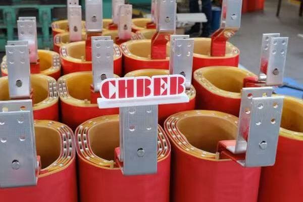
Analyzing Top 3 Phase Transformer Brands
Let’s explore the strengths and specialties of these leading brands:
- ABB
- TBEA
- Schneider Electric
- Shunted
ABB
ABB is known for its innovative and reliable transformers:
- Specializes in epoxy resin cast dry-type transformers
- Often uses Dyn11 vector group configuration
- Excellent for commercial and healthcare applications
I recently worked on a hospital renovation project where we chose ABB’s dry-type transformers. Their low noise levels and fire-resistant properties were crucial for the sensitive hospital environment.
TBEA
TBEA is renowned for its efficient oil-immersed transformers:
- Often utilizes YNd11 vector group configuration
- Popular in industrial settings and national grid projects
- Known for high efficiency and reliability
During a large industrial park development, we implemented TBEA’s oil-immersed transformers. Their ability to handle high loads efficiently was perfect for thediverse power needs of multiple manufacturing facilities.
Schneider Electric
Schneider Electric focuses on energy-efficient solutions:
- Offers low-loss winding designs
- Provides comprehensive energy management solutions
- Ideal for data centers and smart building applications
I recall a data center project where Schneider Electric’s transformers were integrated with their energy management system. The result was a highly efficient and easily monitored power distribution setup.
Shunted
Shunted specializes in dry-type transformers:
- Known for innovative ventilation channel designs
- Popular in educational institutions and small substations
- Offers compact solutions for space-constrained applications
In a recent university campus upgrade, we chose Shunted transformers for their compact design and low maintenance requirements, which were perfect for the limited space in campus buildings.
Here’s a comparison table of these top brands:
| Brand | Technology Advantage | Typical Structure | Recommended Application |
|---|---|---|---|
| ABB | Epoxy resin cast dry-type | Dyn11 connection | Commercial & Healthcare |
| TBEA | High-efficiency oil-immersed | YNd11 connection | Industrial & National Grid |
| Schneider Electric | Energy-efficient solutions | Low-loss winding design | Data Centers |
| Shunted | Dry-type with ventilation innovation | Ventilation channel design | Educational & Small Substations |
Key considerations when comparing these brands:
- Application-specific requirements: Match the brand’s specialty to your project needs
- Efficiency ratings: Compare energy efficiency, especially for long-term operations
- Environmental factors: Consider dry-type vs. oil-immersed based on installation location
- Maintenance needs: Evaluate the long-term maintenance requirements and costs
- Integration capabilities: Look at compatibility with existing systems or future upgrades
In my experience, the choice of brand often comes down to the specific requirements of the project. For instance, in a recent industrial project where high efficiency and the ability to handle harsh environments were crucial, TBEA’s oil-immersed transformers were the clear choice. However, for a university library renovation where fire safety and low noise were priorities, ABB’s dry-type transformers were more suitable.
Remember, while these are top brands, the best choice depends on your specific needs. Always consider factors like local support, warranty terms, and compatibility with your existing infrastructure when making your decision.
As we move on to discuss how to select the right 3 phase transformer for your project, keep these brand comparisons in mind. They’ll serve as a valuable reference point in understanding how different manufacturers cater to various application needs and technical requirements.
How to Select the Right 3 Phase Transformer for Your Project?
Are you feeling overwhelmed by the process of choosing the right 3 phase transformer for your project? You’re not alone. Many engineers and project managers struggle with this critical decision. But what if you had a clear, step-by-step approach to ensure you select the perfect transformer for your specific needs?
Selecting the right 3 phase transformer involves assessing load requirements, considering environmental factors, evaluating efficiency standards, and understanding installation constraints. Key factors include kVA rating, primary and secondary voltages, vector group, impedance, and cooling method. Also, consider future expansion needs, maintenance requirements, and compliance with relevant IEC or ANSI standards for your region.
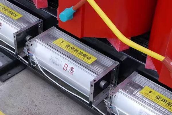
Key Steps in Selecting a 3 Phase Transformer
Let’s break down the selection process into manageable steps:
- Determine Load Requirements
- Consider Environmental Factors
- Evaluate Efficiency and Standards
- Assess Installation and Maintenance Needs
- Plan for Future Expansion
Determine Load Requirements
Start by accurately assessing your power needs:
- Calculate total kVA required for all connected loads
- Consider load factor and diversity factor
- Determine required primary and secondary voltages
I once worked on a project where underestimating the load led to an undersized transformer. We had to replace it within a year, causing unnecessary downtime and extra costs. Always err on the side of caution when calculating load requirements.
Consider Environmental Factors
The installation environment plays a crucial role:
- Indoor vs. outdoor installation
- Ambient temperature range
- Altitude (affects cooling efficiency)
- Presence of corrosive or humid conditions
During a coastal industrial project, we opted for specially designed transformers with enhanced corrosion resistance. This decision significantly extended the transformer’s lifespan in the harsh, salt-laden environment.
Evaluate Efficiency and Standards
Energy efficiency is increasingly important:
- Check for compliance with efficiency standards (e.g., DOE 2016 in the US)
- Consider total cost of ownership, including energy losses
- Ensure compliance with relevant IEC or ANSI standards
In a recent commercial building project, choosing a high-efficiency transformer led to significant energy savings over time, justifying the higher initial investment.
Assess Installation and Maintenance Needs
Consider practical aspects of installation and upkeep:
- Space constraints and weight limitations
- Noise level requirements (especially for indoor installations)
- Ease of maintenance and accessibility
- Cooling method (ONAN, ONAF, etc.)
I recall a project where we had to use a compact dry-type transformer due to severe space limitations in an urban substation. Understanding these constraints early in the selection process was crucial.
Plan for Future Expansion
Think ahead to potential future needs:
- Consider potential load growth
- Evaluate the possibility of paralleling transformers
- Look at options for easy capacity upgrades
Here’s a quick reference table for key selection criteria:
| Criterion | Considerations | Impact |
|---|---|---|
| kVA Rating | Total load, future growth | Determines capacity |
| Voltage Levels | Primary/secondary requirements | Affects system compatibility |
| Efficiency | Energy losses, standards compliance | Influences operating costs |
| Environmental | Indoor/outdoor, temperature, altitude | Affects design and longevity |
| Maintenance | Accessibility, cooling method | Impacts long-term costs |
Key tips for selecting the right 3 phase transformer:
- Always include a safety margin in your load calculations
- Consider the total cost of ownership, not just the initial price
- Consult with manufacturers or experts for complex applications
- Review case studies of similar installations
- Consider conducting site visits to see transformers in similar applications
In my experience, successful transformer selection comes down to a balance of technical requirements, practical considerations, and future-proofing. I’ve seen projects succeed when all these factors were carefully weighed, and struggle when even one was overlooked.
Remember, selecting the right transformer is not just about meeting current needs; it’s about ensuring your power distribution system remains efficient, reliable, and adaptable for years to come. By following these steps and considering all relevant factors, you can make an informed decision that will serve your project well into the future.
Conclusion
3 phase distribution transformers are crucial components in modern power systems, offering efficient and reliable power distribution for various applications. Understanding their structure, operation, and selection criteria is essential for engineers and project managers. By considering factors like load requirements, efficiency, and environmental conditions, you can choose the right transformer to ensure optimal performance and longevity in your power distribution system.
Remember, at chbeb-ele, we’re not just sharing information – we’re empowering you to be part of the solution in creating a secure, clean, and efficient energy future. Let’s continue this journey together.
Are you struggling to understand the nuances of distribution transformer diagrams across different installation types? You’re not alone. Many engineers and project managers find themselves confused when faced with the varied requirements of residential, industrial, and utility installations. But what if you could easily interpret and apply these diagrams to ensure optimal performance and safety in any setting?
Distribution transformer diagrams vary by installation type—residential, industrial, or utility—based on voltage levels, load characteristics, and layout needs. This guide explains how to read and apply these diagrams for different use cases, helping project engineers and utility planners ensure safe and efficient system integration.

In this comprehensive guide, I’ll walk you through the key aspects of distribution transformer diagrams for various installation types. Whether you’re working on a residential project, an industrial facility, or a utility-scale installation, this article will provide you with the insights you need to navigate these crucial diagrams effectively.
What Is a Distribution Transformer Diagram?
Have you ever wondered why distribution transformer diagrams look so complex? These intricate drawings serve a crucial purpose, but their complexity can be overwhelming. So, what exactly are these diagrams, and why are they so important for different installation types?
A distribution transformer diagram is a technical drawing that illustrates the internal connections, components, and electrical pathways of a transformer used in power distribution systems. It includes wiring schematics, connection points, and component layouts specific to residential, industrial, or utility applications. These diagrams are essential for proper installation, maintenance, and troubleshooting in various settings.
Understanding Distribution Transformer Diagrams
Let’s break down the key elements of these diagrams:
- Basic Components
- Connection Representations
- Safety Features
- Application-Specific Elements
Basic Components
All distribution transformer diagrams share some common elements:
- Primary and secondary windings
- Core representation
- Bushing terminals
- Tap changer (if applicable)
I remember a project where a junior engineer overlooked the tap changer representation, leading to incorrect voltage settings. This experience highlighted the importance of understanding even the basic components in these diagrams.
Connection Representations
Diagrams show how the transformer is connected to the system:
- Primary side connections (usually higher voltage)
- Secondary side connections (lower voltage for distribution)
- Grounding points
- Vector group notation (e.g., Dyn11)
During a recent industrial installation, the correct interpretation of the vector group notation was crucial in ensuring proper phase relationships between primary and secondary sides.
Safety Features
Safety is paramount, and diagrams reflect this:
- Surge arresters
- Fuse locations
- Protective relays
- Isolation points
I once worked on a utility project where overlooking a surge arrester in the diagram led to inadequate protection planning. This taught me to always pay close attention to safety features in transformer diagrams.
Application-Specific Elements
Different installations require specific elements:
- Residential: Focus on single-phase connections, compact design
- Industrial: Emphasis on load capacity, multiple output circuits
- Utility: Inclusion of metering equipment, SCADA interfaces
Here’s a quick reference table for diagram elements across applications:
| Element | Residential | Industrial | Utility |
|---|---|---|---|
| Voltage Levels | Low (e.g., 240V) | Medium (e.g., 480V) | High (kV range) |
| Phase Configuration | Often single-phase | Typically three-phase | Three-phase |
| Protection Devices | Simple fusing | Complex relay systems | Advanced protection schemes |
| Metering | Basic | Power quality monitoring | Advanced metering infrastructure |
Understanding these elements is crucial for correctly interpreting and applying distribution transformer diagrams. In my experience, the ability to quickly identify application-specific features in a diagram can significantly streamline the planning and installation process.
As we delve deeper into the variations across different installation types, keep in mind that these diagrams are not just technical drawings – they’re roadmaps for ensuring safe, efficient, and reliable power distribution in diverse settings.
Diagram Variations by Application Type?
Are you finding it challenging to distinguish between transformer diagrams for different applications? You’re not alone. Many professionals struggle to identify the unique features that set residential, industrial, and utility transformer diagrams apart. But why do these variations matter, and how can understanding them improve your project outcomes?
Distribution transformer diagrams vary significantly based on their application. Residential diagrams focus on low voltage, compact layouts, and safety features for domestic use. Industrial diagrams emphasize higher capacities, multi-load integration, and power quality monitoring. Utility diagrams showcase high voltage connections, advanced protection schemes, and SCADA integration for grid management. Understanding these variations is crucial for proper installation and system integration.
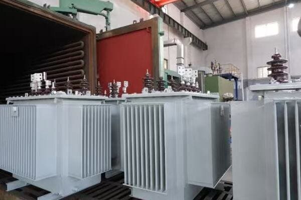
Exploring Application-Specific Diagram Features
Let’s dive into the unique characteristics of each application type:
- Residential Transformer Diagrams
- Industrial Transformer Diagrams
- Utility Transformer Diagrams
Residential Transformer Diagrams
Residential diagrams have specific features tailored for domestic power distribution:
- Low voltage focus (typically 120/240V in North America)
- Single-phase or split-phase configurations
- Compact design representations
- Emphasis on safety features for public areas
I recall a project where we were retrofitting an old neighborhood with updated transformers. The compact nature of the residential diagrams was crucial in planning installations in space-constrained urban areas.
Key elements in residential diagrams:
- Simplified protection schemes (often just fuses)
- Clear labeling for service drops
- Grounding representations for safety
- Weatherproof enclosure details
Industrial Transformer Diagrams
Industrial applications require more complex diagrams:
- Higher voltage and capacity ratings
- Three-phase configurations
- Multiple secondary outputs for diverse loads
- Power quality monitoring integration
During an industrial park development, I noticed how the transformer diagrams had to account for vastly different load types – from office buildings to manufacturing plants. This variety was clearly reflected in the complexity of the diagrams.
Important features in industrial diagrams:
- Detailed load-side connection options
- Power factor correction equipment
- Harmonic mitigation devices
- Advanced protection relay schematics
Utility Transformer Diagrams
Utility-scale diagrams are the most complex:
- High voltage primary connections (often in kV range)
- Substation integration details
- Advanced protection and control schemes
- SCADA system interfaces
I once worked on a smart grid project where the utility transformer diagrams had to incorporate advanced monitoring and control features. The level of detail in these diagrams was crucial for successful integration with the broader grid management systems.
Critical elements in utility diagrams:
- Detailed primary and secondary bushing arrangements
- Tap changer mechanisms and controls
- Extensive metering and monitoring points
- Fault detection and isolation schemes
Here’s a comparison table of key diagram features across applications:
| Feature | Residential | Industrial | Utility |
|---|---|---|---|
| Voltage Levels | Low (120/240V) | Medium (480V-4.16kV) | High (>4.16kV) |
| Phase Configuration | Single/Split-phase | Three-phase | Three-phase |
| Protection Complexity | Low | Medium | High |
| Size Representation | Compact | Medium | Large |
| Control Systems | Minimal | Moderate | Extensive |
| Environmental Factors | Weather resistance | Harsh conditions | Substation environment |
Understanding these variations is crucial for several reasons:
- Proper equipment selection and sizing
- Ensuring compliance with application-specific standards
- Facilitating effective communication between designers, installers, and operators
- Optimizing installation layouts and space utilization
- Enhancing safety and reliability in diverse operating environments
In my experience, the ability to quickly identify and interpret these application-specific features can significantly streamline project planning and execution. I remember a case where an industrial diagram was mistakenly used as a reference for a residential installation. The overengineered solution led to unnecessary costs and complications – a situation that could have been easily avoided with proper diagram identification.
As we continue to explore the nuances of distribution transformer diagrams, keep in mind that these variations are not just technical distinctions. They represent fundamental differences in how power is distributed and utilized across different sectors of our electrical infrastructure. By mastering these distinctions, you’ll be better equipped to handle diverse projects and ensure optimal performance in any setting.
Regional Differences in Diagram Design?
Have you ever noticed how transformer diagrams can vary significantly from one region to another? This variation isn’t just a matter of style – it reflects important differences in standards, practices, and environmental factors across different parts of the world. But why do these regional differences exist, and how can understanding them help you in your projects?
Regional differences in distribution transformer diagrams stem from varying standards, environmental conditions, and local practices. Middle Eastern diagrams often emphasize high-temperature designs and IEC standards. Southeast Asian diagrams focus on compact distribution and multi-load branching. Latin American diagrams prioritize installation clarity and maintainability. Understanding these regional nuances is crucial for international projects and compliance with local regulations.

Exploring Regional Diagram Characteristics
Let’s examine the unique features of transformer diagrams in different regions:
- Middle Eastern Diagram Designs
- Southeast Asian Diagram Approaches
- Latin American Diagram Practices
Middle Eastern Diagram Designs
Middle Eastern transformer diagrams have distinct characteristics:
- Emphasis on high-temperature operation
- Preference for IEC standard symbols
- Detailed dust and sand protection features
- Focus on oil preservation systems
I once worked on a project in Saudi Arabia where the transformer diagram had to include specific details about enhanced cooling systems and sand-resistant enclosures. This experience highlighted the importance of adapting designs to harsh desert environments.
Key elements in Middle Eastern diagrams:
- Extended temperature range specifications
- Detailed insulation class notations
- Sand and dust filtration system representations
- Enhanced oil circulation and cooling diagrams
Southeast Asian Diagram Approaches
Southeast Asian diagrams often reflect unique regional needs:
- Compact designs for urban density
- Emphasis on moisture resistance
- Multi-load branching configurations
- Integration with local grid peculiarities
During a project in Singapore, I noticed how the transformer diagrams had to account for extremely space-constrained installations and high humidity environments. The level of detail in spatial planning within these diagrams was impressive.
Important features in Southeast Asian diagrams:
- Space-saving layout representations
- Detailed moisture sealing techniques
- Multiple low-voltage output configurations
- Compatibility with local voltage fluctuation ranges
Latin American Diagram Practices
Latin American transformer diagrams often prioritize:
- Clear installation instructions
- Robust grounding schemes
- Flexibility for varied voltage standards
- Easy maintenance access points
I recall a project in Brazil where the emphasis on clear, visually intuitive diagrams was crucial for coordinating with local installation teams. The diagrams included detailed step-by-step installation guides, which greatly facilitated on-site work.
Critical elements in Latin American diagrams:
- Bilingual labeling (often Spanish/Portuguese and English)
- Detailed grounding and bonding representations
- Voltage range adaptability features
- Maintenance access point highlights
Here’s a comparison table of regional diagram characteristics:
| Feature | Middle East | Southeast Asia | Latin America |
|---|---|---|---|
| Environmental Focus | Heat and sand resistance | Moisture and space efficiency | Versatility and ease of maintenance |
| Preferred Standards | IEC | Mix of IEC and local standards | Often compatible with both IEC and ANSI |
| Key Design Emphasis | Cooling systems | Compact multi-load designs | Clear installation guidance |
| Unique Elements | Sand filters, extended temp. ranges | Space-saving layouts, humidity protection | Bilingual labels, flexible voltage settings |
Understanding these regional differences is crucial for several reasons:
- Ensuring compliance with local regulations and standards
- Adapting designs to specific environmental challenges
- Facilitating effective communication with local teams and authorities
- Optimizing transformer performance for regional power quality issues
- Streamlining installation and maintenance processes in different cultural contexts
In my experience, recognizing and adapting to these regional nuances can make or break international projects. I remember a case where a European-designed transformer diagram was used without modification for a Southeast Asian project. The lack of consideration for the region’s high humidity and space constraints led to significant on-site modifications and delays.
As we continue to explore the global landscape of distribution transformer diagrams, it’s important to remember that these regional differences are not just technical curiosities. They represent the culmination of local experiences, environmental adaptations, and regulatory evolutions. By mastering these regional variations, you’ll be better equipped to handle diverse international projects and ensure optimal transformer performance in any global context.
How Top Brands Customize Diagrams for Each Use Case?
Have you ever wondered how leading transformer manufacturers adapt their diagrams for different markets and applications? This customization is not just about branding – it’s a crucial aspect of ensuring that transformers meet specific regional and application needs. But how do top brands approach this customization, and what can we learn from their practices?
Top transformer brands customize their diagrams based on regional standards and application-specific requirements. ABB often uses IEC symbols with heat-optimized designs for Middle Eastern projects. TBEA excels in compact, multi-load diagrams for Southeast Asian markets. Shunted focuses on clear isolation structures for commercial buildings. Siemens integrates detailed SCADA symbols for Latin American utility projects. Understanding these customizations helps in selecting the right transformer for specific use cases.
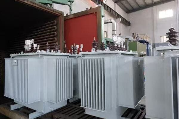
Brand-Specific Diagram Customization Approaches
Let’s examine how some top brands tailor their transformer diagrams:
- ABB’s Middle Eastern Adaptations
- TBEA’s Southeast Asian Specializations
- Shunted’s Commercial Building Focus
- Siemens’ Latin American Utility Designs
ABB’s Middle Eastern Adaptations
ABB’s approach to Middle Eastern markets includes:
- Extensive use of IEC standard symbols
- Enhanced heat dissipation design representations
- Detailed sand and dust protection features
- Emphasis on oil preservation systems
I once worked with ABB on a large substation project in the UAE. Their diagrams included intricate details of enhanced cooling systems and sand-resistant enclosures, which were crucial for the harsh desert environment.
Key features in ABB’s Middle Eastern diagrams:
- Extended temperature range specifications
- Detailed insulation class notations
- Sand and dust filtration system representations
- Enhanced oil circulation and cooling diagrams
TBEA’s Southeast Asian Specializations
TBEA’s diagrams for Southeast Asian markets focus on:
- Compact designs for urban density
- Multi-transformer interlinking schemes
- Clear grounding and isolation representations
- Adaptation to local grid characteristics
During a recent project in Malaysia, I was impressed by TBEA’s approach to designing compact transformer layouts that could fit into tight urban spaces while still maintaining clear safety and maintenance access points.
Notable elements in TBEA’s Southeast Asian diagrams:
- Space-efficient layout representations
- Detailed moisture sealing techniques
- Multiple low-voltage output configurations
- Local voltage fluctuation compensation features
Shunted’s Commercial Building Focus
Shunted’s diagrams for commercial applications emphasize:
- Clear representation of dry-type transformer structures
- Detailed ventilation and cooling layouts
- Noise reduction feature illustrations
- Integration with building management systems
I recall a project where Shunted’s clear diagram of a dry-type transformer’s isolation structure was instrumental in convincing a client of its suitability for their high-rise office building.
Important aspects of Shunted’s commercial building diagrams:
- Thermal management system details
- Acoustic enclosure representations
- Fire safety feature illustrations
- Building automation system interface points
Siemens’ Latin American Utility Designs
Siemens’ approach to Latin American utility projects includes:
- Detailed SCADA integration symbols
- Robust grounding scheme representations
- Flexibility for varied regional voltage standards
- Clear maintenance access point illustrations
Working on a smart grid project in Brazil, I saw firsthand how Siemens’ detailed SCADA integration diagrams facilitated seamless communication between the transformers and the broader grid management system.
Key elements in Siemens’ Latin American utility diagrams:
- Comprehensive SCADA symbol sets
- Detailed grounding and bonding representations
- Voltage range adaptability features
- Maintenance-friendly design highlights
Here’s a comparison table of brand-specific diagram features:
| Brand | Regional Focus | Key Diagram Features | Unique Selling Point |
|---|---|---|---|
| ABB | Middle East | IEC symbols, heat optimization | Desert-ready designs |
| TBEA | Southeast Asia | Compact, multi-load layouts | Urban space efficiency |
| Shunted | Commercial Buildings | Clear isolation structures | Building integration |
| Siemens | Latin American Utilities | Detailed SCADA integration | Smart grid readiness |
Understanding these brand-specific approaches is valuable for several reasons:
- Selecting the most suitable transformer for specific regional and application needs
- Anticipating potential challenges in installation and operation3. Leveraging brand expertise for particular environmental or operational conditions
- Facilitating smoother integration with existing systems or infrastructure
- Optimizing maintenance and operational procedures based on manufacturer-specific features
In my experience, recognizing these brand-specific customizations can significantly impact project success. I remember a case where we initially considered a generic transformer design for a Southeast Asian urban project. After reviewing TBEA’s specialized compact designs, we realized the significant space savings and improved integration possibilities, which ultimately led to a more efficient and cost-effective installation.
As we navigate the diverse landscape of transformer diagrams, it’s crucial to remember that these brand customizations are not just marketing differentiators. They represent years of experience and adaptation to specific regional and application challenges. By understanding and leveraging these customized approaches, you can ensure that your transformer selections are optimally suited to the unique demands of each project.
Key Symbols and Layouts to Know?
Are you finding yourself puzzled by the array of symbols and layouts in distribution transformer diagrams? You’re not alone. Many engineers and technicians struggle to decipher these critical elements across different application types. But what if you had a clear guide to help you understand each symbol and layout, regardless of whether it’s for residential, industrial, or utility use?
Key symbols and layouts in distribution transformer diagrams vary by application but share common elements. Residential diagrams often feature simple single-phase symbols and compact layouts. Industrial diagrams include three-phase symbols, multiple load connections, and power quality monitoring layouts. Utility diagrams showcase complex protection schemes, SCADA symbols, and high-voltage connection layouts. Understanding these elements is crucial for accurate diagram interpretation and effective transformer installation.
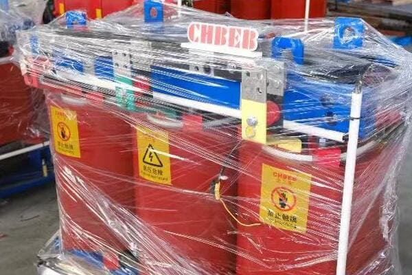
Essential Symbols and Layouts Across Applications
Let’s break down the key elements you need to know:
- Common Symbols Across All Applications
- Residential-Specific Symbols and Layouts
- Industrial Diagram Elements
- Utility-Scale Diagram Features
Common Symbols Across All Applications
Certain symbols are universal across transformer diagrams:
- Transformer core: Usually represented by two or more parallel lines
- Windings: Typically shown as zigzag lines
- Bushings: Often depicted as small circles or rectangles on the transformer outline
- Ground symbols: Represented by multiple horizontal lines decreasing in length
I once worked on a project where a junior engineer confused bushing symbols with tap changer representations. This experience highlighted the importance of understanding even the most basic symbols in transformer diagrams.
Residential-Specific Symbols and Layouts
Residential diagrams have unique features:
- Single-phase symbols: Often simplified representations
- Service drop connections: Clear labeling for household connections
- Simple protection schemes: Basic fuse symbols
During a recent residential area upgrade, the clear representation of service drop connections in the diagrams was crucial for efficient installation and minimizing disruption to homeowners.
Industrial Diagram Elements
Industrial diagrams include more complex elements:
- Three-phase symbols: More detailed winding representations
- Multiple secondary outputs: Often labeled for different voltage levels
- Power factor correction equipment: Capacitor bank symbols
- Harmonic filter representations: Inductor and capacitor combinations
I recall a manufacturing plant project where the correct interpretation of power factor correction symbols in the diagram was essential for addressing the facility’s specific power quality needs.
Utility-Scale Diagram Features
Utility diagrams are the most complex:
- High voltage bushings: Detailed insulator representations
- SCADA interface symbols: Communication and control elements
- Advanced protection schemes: Relay and circuit breaker combinations
- Tap changer mechanisms: Detailed switching representations
In a recent smart grid project, understanding the SCADA interface symbols in utility transformer diagrams was critical for ensuring proper integration with the broader grid management system.
Here’s a quick reference table for key symbols across applications:
| Symbol Type | Residential | Industrial | Utility |
|---|---|---|---|
| Transformer Core | Simple dual-line | Detailed multi-line | Complex multi-section |
| Windings | Basic zigzag | Multiple zigzags | Detailed with taps |
| Protection | Fuse symbols | Relay and breaker combo | Complex protection schemes |
| Connections | Single-phase | Three-phase, multi-output | High voltage, SCADA links |
Key considerations when interpreting symbols and layouts:
- Always refer to the diagram’s legend or key for specific symbol meanings
- Pay attention to voltage levels indicated near connection points
- Note the differences in protection scheme complexity across applications
- Understand how layout reflects physical arrangement versus schematic representation
- Be aware of regional variations in symbol usage, especially in international projects
In my experience, proficiency in reading these symbols and layouts comes with practice and exposure to diverse diagrams. I encourage technicians and engineers to study diagrams from various manufacturers and for different applications, even when not directly working on a related project.
Remember, accurate interpretation of these symbols and layouts is not just about technical correctness; it’s about ensuring safety, efficiency, and reliability in transformer installations. Whether you’re working on a simple residential setup or a complex utility-scale project, a solid understanding of these elements will serve you well throughout your career in the power distribution field.
Best Practices for Installation Diagram Interpretation?
Are you finding it challenging to translate transformer diagrams into successful installations? This common struggle can lead to costly errors and safety risks if not addressed properly. But how can you ensure that you’re interpreting these crucial diagrams correctly, especially when dealing with different applications and regional variations?
Best practices for interpreting installation diagrams include: thoroughly reviewing legends and notes, cross-referencing with specifications, considering physical layout implications, verifying protection schemes, and understanding regional standards. For residential installations, focus on service connections. In industrial settings, pay attention to load distribution. For utility projects, carefully interpret control and monitoring interfaces. Always verify grounding and safety features across all applications.
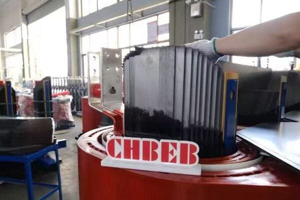
Key Strategies for Effective Diagram Interpretation
Let’s explore essential practices for interpreting transformer installation diagrams:
- Pre-Installation Review Process
- Application-Specific Considerations
- Safety and Compliance Checks
- Practical Installation Tips
Pre-Installation Review Process
Before beginning any installation:
- Thoroughly review the legend and symbol key
- Cross-reference the diagram with written specifications
- Verify voltage levels and capacity ratings
- Check for any site-specific notes or special instructions
I once worked on a project where skipping the pre-installation review led to a misunderstanding of a custom symbol. This resulted in incorrect wiring that had to be completely redone, causing significant delays and additional costs.
Application-Specific Considerations
Different applications require focused attention on certain aspects:
Residential:
- Verify service drop connections
- Check for proper grounding representations
- Ensure compliance with local residential codes
Industrial:
- Pay close attention to load distribution across outputs
- Verify power factor correction and harmonic mitigation features
- Check for integration with existing industrial systems
Utility:
- Carefully interpret SCADA and control interface representations
- Verify high voltage connection details
- Ensure compatibility with utility-specific protection schemes
During a recent industrial installation, carefully interpreting the load distribution diagram was crucial in balancing power supply across various manufacturing processes, ultimately optimizing the facility’s energy efficiency.
Safety and Compliance Checks
Prioritize safety in your interpretation:
- Double-check all grounding and bonding representations
- Verify that protection devices are correctly represented and positioned
- Ensure compliance with relevant safety standards (e.g., NFPA, IEC)
- Check for any special environmental protection features
I recall a utility project where a misinterpretation of the grounding scheme in the diagram led to a potential safety hazard. Fortunately, our rigorous compliance check caught this before installation, avoiding what could have been a dangerous situation.
Practical Installation Tips
When moving from diagram to actual installation:
- Create a step-by-step installation checklist based on the diagram
- Mark up a copy of the diagram to note any site-specific adaptations
- Use the diagram to plan equipment positioning and cable routing
- Regularly refer back to the diagram during installation to ensure accuracy
Here’s a quick reference table for interpretation focus areas:
| Application | Key Focus Areas | Common Pitfalls |
|---|---|---|
| Residential | Service connections, grounding | Overlooking local code specifics |
| Industrial | Load balancing, power quality | Misinterpreting complex protection schemes |
| Utility | SCADA integration, HV connections | Underestimating control interface complexity |
Best practices for diagram interpretation across all applications:
- Always start with a thorough review of the entire diagram before focusing on details
- When in doubt, consult with the diagram creator or manufacturer for clarification
- Consider creating a digital or physical mock-up for complex installations
- Conduct regular team briefings to ensure all members understand the diagram
- Document any deviations from the diagram during installation for future reference
In my experience, successful diagram interpretation is as much about systematic approach as it is about technical knowledge. I’ve seen projects succeed where teams took the time to collectively review and discuss the diagram before starting work, and struggle when this crucial step was rushed or overlooked.
Remember, accurate diagram interpretation is the foundation of a successful transformer installation. It ensures not only the correct functioning of the transformer but also the safety of the installation team and end-users. By following these best practices and staying attentive to the nuances of each application type, you can significantly improve the efficiency and reliability of your transformer installations.
As you apply these practices in your projects, you’ll find that your ability to quickly and accurately interpret even the most complex diagrams will improve, making you a more valuable asset in the field of power distribution and transformer installation.
Conclusion: Choosing the Right Diagram for Your Market and Project
Understanding and correctly interpreting distribution transformer diagrams is crucial for successful installations across residential, industrial, and utility applications. By recognizing regional variations, brand-specific customizations, and application-specific symbols, you can ensure optimal transformer selection and installation. Always prioritize safety, comply with local standards, and consider the unique needs of each project when interpreting and applying these diagrams.
Remember, at chbeb-ele, we’re not just sharing information – we’re empowering you to be part of the solution in creating a secure, clean, and efficient energy future. Let’s continue this journey together.
Are you struggling to navigate the complex world of international transformer diagram standards? You’re not alone. Many engineers and project managers find themselves confused when dealing with IEC and ANSI standards, especially in global projects. But what if you could easily understand and apply these standards to ensure your projects run smoothly across borders?
IEC and ANSI transformer diagram standards differ in symbols, layout conventions, and compliance requirements. IEC is used in Europe and Asia, while ANSI is common in North America. Understanding these differences is essential for global projects, ensuring technical compatibility and smooth cross-border transformer installations.
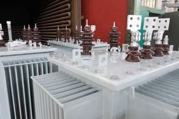
In this comprehensive guide, I’ll walk you through the key differences between IEC and ANSI standards for transformer diagrams. Whether you’re working on international projects or simply want to expand your knowledge, this article will provide you with the insights you need to navigate these crucial standards effectively.
Why Understanding IEC and ANSI Standards Matters?
Have you ever wondered why there’s so much fuss about diagram standards in transformer projects? The choice between IEC and ANSI standards can significantly impact your project’s success, but why is this understanding so crucial for engineers and project managers?
Understanding IEC and ANSI standards is vital for ensuring technical compatibility, regulatory compliance, and effective communication in global transformer projects. These standards affect diagram interpretation, equipment specifications, and installation procedures. Misalignment between standards can lead to costly errors, project delays, and safety issues, especially in cross-border or export projects.
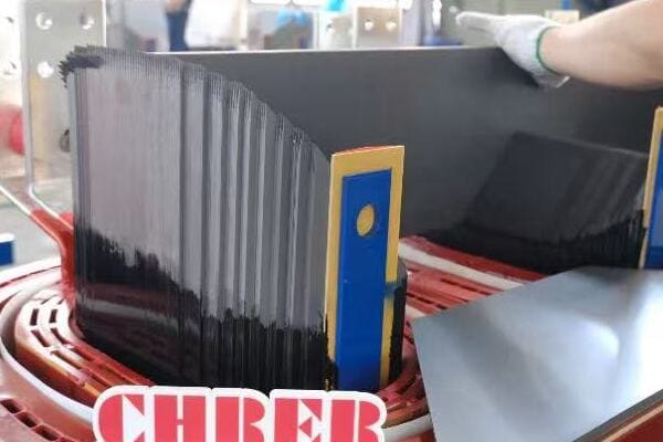
The Impact of Standards on Transformer Projects
Let’s explore why these standards are so important:
- Technical Compatibility
- Regulatory Compliance
- Project Communication
- Cost Implications
Technical Compatibility
Different standards can lead to significant technical differences:
- Component specifications may vary
- Connection methods might differ
- Safety features could have different requirements
I once worked on a project where an IEC-designed transformer was being installed in an ANSI-standard facility. The mismatch in bushing specifications led to connection issues that required costly on-site modifications.
Regulatory Compliance
Compliance with the correct standard is often a legal requirement:
- Some countries mandate specific standards
- Non-compliance can result in project rejection or legal issues
- Certification processes differ between IEC and ANSI
During a recent export project to the US, we had to completely redraw our diagrams to ANSI standards to meet local regulatory requirements. This unexpected step added weeks to our project timeline.
Project Communication
Standards affect how information is conveyed and understood:
- Symbol differences can lead to misinterpretation
- Layout conventions vary, affecting how diagrams are read
- Terminology differences can cause confusion
I recall a situation where a misunderstanding of grounding symbols between IEC and ANSI diagrams led to an incorrect installation. Clear communication about which standard was being used could have prevented this issue.
Cost Implications
Misalignment of standards can have significant financial impacts:
- Rework due to misinterpretation is costly
- Delays from compliance issues can inflate budgets
- Training staff on multiple standards increases operational costs
Here’s a quick overview of the potential impacts:
| Aspect | IEC-ANSI Alignment | IEC-ANSI Misalignment |
|---|---|---|
| Project Timeline | On schedule | Potential delays |
| Installation Ease | Smooth | Complications likely |
| Regulatory Approval | Straightforward | May require revisions |
| Cost | As budgeted | Potential overruns |
Understanding these standards is not just about technical knowledge; it’s about ensuring project success. In my experience, projects that proactively address standard differences from the outset tend to run more smoothly and are more likely to meet their timelines and budgets.
Key considerations when dealing with IEC and ANSI standards:
- Identify the relevant standard early in the project planning phase
- Ensure all team members are aware of which standard is being used
- Consider providing training on both standards for key personnel
- Develop processes for converting between standards when necessary
- Build relationships with experts in both IEC and ANSI standards
Remember, the goal is not just compliance, but effective communication and seamless project execution. By understanding the importance of these standards and their differences, you can navigate international projects more confidently and avoid costly mistakes.
As we delve deeper into the specifics of IEC and ANSI standards, keep in mind how these differences can impact your projects at every stage, from design to installation and operation.
What Are IEC Standards for Transformer Diagrams?
Are you finding it challenging to understand IEC standards for transformer diagrams? You’re not alone. Many engineers, especially those used to ANSI standards, struggle with the nuances of IEC diagrams. But what exactly are these standards, and how do they differ from what you might be familiar with?
IEC (International Electrotechnical Commission) standards for transformer diagrams are widely used in Europe, Asia, and many other parts of the world. They provide a unified approach to representing transformer components, connections, and functions. IEC diagrams typically feature more graphical symbols, standardized layouts with high voltage on the left, and specific conventions for representing windings, taps, and protection devices.

Understanding IEC Transformer Diagram Standards
Let’s break down the key aspects of IEC transformer diagram standards:
- Symbol Conventions
- Layout and Organization
- Winding Representation
- Protection and Auxiliary Devices
- Application in Different Regions
Symbol Conventions
IEC standards use distinct symbols for transformer components:
- Transformers: Often represented by circles or ovals with lines inside
- Circuit breakers: Typically shown as two parallel lines with a slash
- Disconnectors: Usually depicted as a small gap in the line
I remember a project where an engineer familiar only with ANSI symbols misinterpreted an IEC circuit breaker symbol as a disconnector. This highlights the importance of understanding these symbol differences.
Layout and Organization
IEC diagrams follow specific layout conventions:
- High voltage side is typically on the left
- Low voltage side is usually on the right
- Auxiliary components are often shown at the bottom
During a recent international collaboration, our team’s adherence to these IEC layout conventions greatly facilitated communication with our European partners, streamlining the design review process.
Winding Representation
IEC standards have unique ways of showing transformer windings:
- Primary windings are often represented by thicker lines
- Secondary windings are usually shown with thinner lines
- Tertiary windings, if present, are typically depicted in the middle
I once worked on a project where understanding these winding representations was crucial in identifying a design flaw in a complex three-winding transformer.
Protection and Auxiliary Devices
IEC diagrams include standardized representations for various devices:
- Buchholz relays: Often shown as a small circle with internal markings
- Temperature indicators: Usually depicted as a thermometer symbol
- Tap changers: Represented with specific symbols indicating type (on-load or off-circuit)
In a recent retrofit project, correctly interpreting these IEC symbols for protection devices was essential in ensuring the new equipment integrated properly with the existing protection scheme.
Application in Different Regions
IEC standards are widely adopted but with some regional variations:
- Europe: Strict adherence to IEC standards
- Asia: Generally follows IEC with some local modifications
- Middle East: Often requires IEC compliance for international projects
Here’s a quick reference table for IEC diagram characteristics:
| Feature | IEC Standard Approach |
|---|---|
| Voltage Sides | High voltage on left |
| Symbol Style | More graphical |
| Winding Representation | Thickness indicates voltage level |
| Protection Devices | Standardized symbols |
| Global Acceptance | High in Europe and Asia |
Key considerations when working with IEC transformer diagrams:
- Familiarize yourself with IEC symbol conventions, especially if you’re used to ANSI standards
- Pay attention to the layout, as it provides quick insights into the transformer configuration
- Understand the significance of line thickness in winding representations
- Be aware of the standardized symbols for protection and auxiliary devices
- Consider regional variations in IEC standard application
In my experience, proficiency in reading and creating IEC transformer diagrams is invaluable for international projects. I’ve seen how this knowledge can prevent misunderstandings, reduce errors, and facilitate smoother collaborations across borders.
As we move forward, we’ll explore ANSI standards and how they compare to IEC. Understanding both will give you a comprehensive view of global transformer diagram practices, enhancing your ability to work on diverse projects and communicate effectively with international teams.
What Are ANSI Standards for Transformer Diagrams?
Are you puzzled by the differences in transformer diagrams when working on North American projects? ANSI standards can seem quite different from IEC, especially if you’re more familiar with the latter. But what exactly are ANSI standards for transformer diagrams, and how do they differ from their international counterparts?
ANSI (American National Standards Institute) standards for transformer diagrams are predominantly used in North America. They feature unique symbol conventions, flexible layout options, and specific labeling practices. ANSI diagrams often use more text-based labels, have different symbols for components like circuit breakers and transformers, and may not adhere to the left-to-right voltage level convention seen in IEC diagrams.
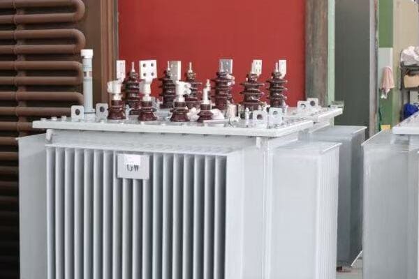
Diving into ANSI Transformer Diagram Standards
Let’s explore the key aspects of ANSI transformer diagram standards:
- Symbol Conventions
- Layout Flexibility
- Winding and Bushing Notation
- Protection and Control Devices
- Application in North America
Symbol Conventions
ANSI standards use distinct symbols that differ from IEC:
- Transformers: Often represented by a square or rectangle with circles inside
- Circuit breakers: Typically shown as a square with an open/close symbol
- Disconnectors: Usually depicted with a specific switch symbol
I recall a project where an engineer accustomed to IEC standards misinterpreted an ANSI circuit breaker symbol, leading to confusion in a protection scheme design. This experience underscored the importance of understanding these symbol differences.
Layout Flexibility
ANSI diagrams offer more flexibility in layout:
- No strict left-to-right voltage level convention
- Components can be arranged based on physical layout or functional grouping
- Emphasis on clarity and readability over standardized positioning
During a recent substation upgrade project in the US, this flexibility allowed us to create diagrams that closely mirrored the physical layout of the equipment, greatly aiding the installation team.
Winding and Bushing Notation
ANSI standards have specific conventions for representing windings and bushings:
- Bushings are typically labeled with H (high voltage) and X (low voltage)
- Winding polarity is often indicated with dot notation
- Tap changers are usually shown with detailed tap position information
I once worked on a transformer specification where understanding these ANSI notations was crucial in correctly defining the winding configuration and tap changer requirements.
Protection and Control Devices
ANSI diagrams include specific representations for various devices:
- Relays: Often shown with ANSI device numbers (e.g., 51 for overcurrent)
- Instrument transformers: Depicted with specific symbols for CTs and PTs
- Control switches: Represented with detailed switch diagrams
In a recent protection upgrade project, correctly interpreting these ANSI symbols and device numbers was essential in ensuring proper integration with existing systems.
Application in North America
ANSI standards are predominantly used in specific regions:
- United States: Primary standard for electrical diagrams
- Canada: Often uses ANSI standards, sometimes with CSA (Canadian Standards Association) modifications
- Parts of Latin America: May use ANSI standards, especially for projects involving US companies
Here’s a quick reference table for ANSI diagram characteristics:
| Feature | ANSI Standard Approach |
|---|---|
| Voltage Representation | No strict left-right convention |
| Symbol Style | More text and number based |
| Winding Notation | H and X labeling, dot notation |
| Protection Devices | ANSI device numbers |
| Regional Use | North America, parts of Latin America |
Key considerations when working with ANSI transformer diagrams:
- Familiarize yourself with ANSI symbol conventions, especially if you’re used to IEC standards
- Understand the flexibility in layout and how it can be used to enhance diagram clarity
- Pay attention to bushing and winding notations, as they differ significantly from IEC
- Learn ANSI device numbers for protection and control devices
- Be aware of potential variations in Canada and Latin America
In my experience, proficiency in reading and creating ANSI transformer diagrams is crucial for any project in North America. I’ve seen how this knowledge can streamline communication with US clients and contractors, reduce errors in specifications, and facilitate smoother project execution.
As we continue, we’ll compare IEC and ANSI standards directly, helping you understand when and how to apply each in your projects. This comparative knowledge is invaluable for engineers and managers working on international projects or dealing with global suppliers.
Key Differences Between IEC and ANSI Diagrams?
Are you finding it challenging to navigate between IEC and ANSI transformer diagrams in your international projects? You’re not alone. Many engineers and project managers struggle with the nuances between these two standards. But what are the key differences you need to be aware of to ensure smooth project execution across different regions?
IEC and ANSI transformer diagrams differ significantly in symbol conventions, layout practices, and notation systems. IEC diagrams typically use more graphical symbols, adhere to a left-to-right voltage level convention, and employ standardized component representations. ANSI diagrams often use more text-based labels, offer flexible layouts, and utilize specific numbering systems for devices. Understanding these differences is crucial for accurate interpretation and effective cross-border collaboration.

Comparing IEC and ANSI Transformer Diagram Standards
Let’s break down the key differences:
- Symbol Conventions
- Layout and Organization
- Winding and Bushing Notation
- Protection and Control Device Representation
- Regional Application and Compliance
Symbol Conventions
The most noticeable difference lies in how components are symbolized:
| Component | IEC Symbol | ANSI Symbol |
|---|---|---|
| Transformer | Circle or oval with lines | Square or rectangle with circles |
| Circuit Breaker | Two parallel lines with slash | Square with open/close symbol |
| Disconnector | Small gap in line | Specific switch symbol |
I recall a project where confusion between IEC and ANSI circuit breaker symbols led to a misunderstanding in a protection scheme. This experience highlighted the importance of clear communication about which standard is being used.
Layout and Organization
Layout conventions differ significantly:
| Aspect | IEC Approach | ANSI Approach |
|---|---|---|
| Voltage Levels | High voltage on left, low on right | No strict convention |
| Component Arrangement | Standardized positioning | Flexible, often based on physical layout |
| Auxiliary Components | Often at bottom of diagram | Can be placed flexibly |
During an international collaboration, we found that creating dual-standard diagrams – with both IEC and ANSI layouts side by side – greatly facilitated communication between our European and American teams.
Winding and Bushing Notation
Notation for windings and bushings varies:
| Feature | IEC Notation | ANSI Notation |
|---|---|---|
| Primary Bushings | Often numbered (1U, 1V, 1W) | Typically labeled (H1, H2, H3) |
| Secondary Bushings | Often numbered (2u, 2v, 2w) | Typically labeled (X1, X2, X3) |
| Winding Polarity | Arrow notation | Dot notation |
I once worked on a transformer specification where misinterpretation of these notations led to an incorrect winding configuration. This taught me the importance of clearly specifying which standard is being used in international tenders.
Protection and Control Device Representation
Representation of protection devices differs:
| Device | IEC Representation | ANSI Representation |
|---|---|---|
| Relays | Specific symbols | ANSI device numbers (e.g., 51 for overcurrent) |
| Instrument Transformers | Standardized symbols | Specific CT and PT symbols |
| Tap Changers | Specific symbols for type | Detailed tap position information |
In a recent protection upgrade project, understanding both IEC and ANSI representations was crucial in integrating new equipment with existing systems from different manufacturers.
Regional Application and Compliance
The use of these standards varies globally:
| Region | Predominant Standard | Notes |
|---|---|---|
| Europe | IEC | Strict adherence |
| Asia | IEC | Some local variations |
| North America | ANSI | Primary standard |
| Middle East | Often IEC | May require dual compliance |
| Latin America | Mixed | Often project-dependent |
During an international expansion project, we had to create dual-standard documentation to meet both European (IEC) and North American (ANSI) requirements. This approach, while initially more time-consuming, significantly smoothed our global operations.
Key considerations when dealing with IEC and ANSI differences:
- Always clearly specify which standard is being used in project documentation
- Develop expertise in both standards for international projects
- Consider creating dual-standard diagrams for global collaborations
- Be aware of regional variations and local requirements
- Invest in training for team members to understand both standards
In my experience, the ability to navigate between IEC and ANSI standards is invaluable in today’s globalized power industry. I’ve seen projects succeed or struggle based on how well these standard differences were managed.
For example, in a recent transformer export project from Europe to the US, we initially faced challenges due to misalignment in protection device representations. By creating a comprehensive cross-reference guide between IEC and ANSI symbols, we were able to bridge this gap effectively, ensuring smooth integration at the installation site.
Remember, the goal isn’t just to know the differences, but to use this knowledge to enhance communication, reduce errors, and facilitate smoother international collaborations. As you work on diverse projects, keep these differences in mind and always strive for clarity in your diagram choices and communications.
Compliance Tips for Export Projects?
Are you preparing for an export project involving transformers and feeling overwhelmed by the compliance requirements for different standards? You’re not alone. Many manufacturers and project managers find navigating the maze of IEC and ANSI standards challenging when exporting transformers. But what if you had a clear roadmap to ensure compliance and smooth project execution?
For export projects, ensure transformer diagrams comply with the destination country’s standards. When exporting to ANSI regions, convert IEC diagrams to ANSI format, paying attention to symbol changes, layout adjustments, and notation differences. For IEC destinations, focus on standardized layouts and graphical symbols. Always provide clear documentation on the standards used and consider dual-standard diagrams for critical components.
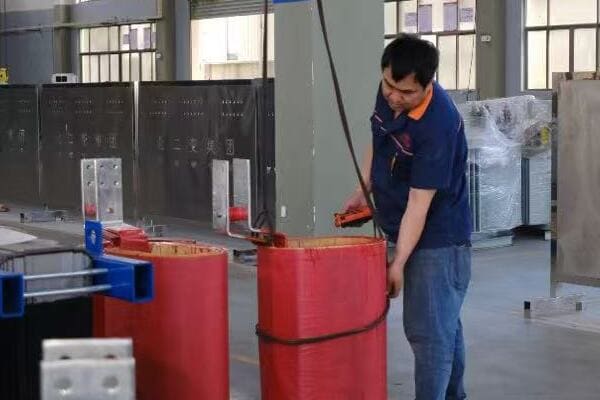
Essential Compliance Strategies for Transformer Export Projects
Let’s explore key strategies to ensure compliance:
- Standard Identification and Conversion
- Documentation and Clarity
- Training and Expertise Development
- Dual-Standard Approaches
- Regulatory Considerations
Standard Identification and Conversion
Start by clearly identifying the required standards:
- Determine the destination country’s preferred standard (IEC or ANSI)
- Assess any local variations or additional requirements
- Plan for conversion if your default standard differs from the destination’s
I once worked on a project exporting transformers from Europe to the US. We had to meticulously convert all our IEC diagrams to ANSI format. This process, while time-consuming, was crucial for regulatory approval and client satisfaction.
Documentation and Clarity
Ensure clear communication of standards in all documentation:
- Explicitly state which standard is used in each diagram
- Provide legend or key explaining symbols and notations
- Include cross-reference guides if multiple standards are involved
During a recent export to the Middle East, we included a comprehensive symbol guide in our documentation package. This proactive approach significantly reduced queries and potential misunderstandings during the approval process.
Training and Expertise Development
Invest in developing your team’s expertise:
- Provide training on both IEC and ANSI standards
- Develop internal experts who can guide standard compliance
- Consider certifications in international standards for key personnel
We implemented a training program for our engineering team to become proficient in both IEC and ANSI standards. This investment paid off in our ability to handle diverse international projects more efficiently.
Dual-Standard Approaches
Consider creating dual-standard documentation for critical components:
- Develop diagrams that show both IEC and ANSI representations
- Use side-by-side layouts for easy comparison
- Highlight key differences to prevent misinterpretation
In a complex project involving multiple international stakeholders, we created dual-standard diagrams for critical transformer components. This approach significantly facilitated communication and reduced errors during the integration phase.
Regulatory Considerations
Be aware of additional regulatory requirements:
- Research specific certifications needed in the destination country
- Understand how standards interact with local regulations (e.g., UL in the US)
- Plan for any additional testing or documentation required for compliance
Here’s a quick reference table for compliance considerations:
| Aspect | IEC Export | ANSI Export |
|---|---|---|
| Symbol Conversion | Minimal if any | Significant changes required |
| Layout Adjustment | Usually minor | May need complete reorganization |
| Additional Certifications | Often CE marking | UL/CSA certifications common |
| Documentation Language | Often multi-lingual | Typically English-only |
| Local Variations | Check for country-specific IEC adoptions | Be aware of differences between US and Canada |
Key tips for ensuring compliance in export projects:
- Start the compliance process early in the project timeline
- Engage with local experts or consultants in the destination country
- Conduct thorough reviews of converted diagrams to catch any missed details
- Prepare for potential site visits or audits by regulatory bodies
- Keep detailed records of all standard compliance efforts and decisions
In my experience, successful compliance in export projects comes down to thorough preparation and clear communication. I recall a project where we initially underestimated the time needed for ANSI conversion of our IEC diagrams. By reallocating resources and bringing in additional expertise, we were able to meet the deadline, but it was a valuable lesson in planning for standard compliance from the outset.
Remember, compliance isn’t just about meeting regulations; it’s about ensuring your transformers can be safely and effectively integrated into the destination’s power systems. By following these tips and maintaining a proactive approach to standards compliance, you can significantly increase the chances of success in your export projects, building a reputation for reliability in the global market.
Case Study: Diagram Misalignment in a US Export Project?
Have you ever wondered about the real-world consequences of misaligned transformer diagrams in international projects? Let’s explore a case study that highlights the critical importance of getting your diagrams right, especially when exporting to markets with different standards.
In a recent US export project, a European manufacturer’s use of IEC diagrams led to significant installation delays and additional costs. The ANSI-accustomed US team misinterpreted protection device symbols and winding configurations. This resulted in incorrect connections, requiring on-site engineering support and diagram conversions. The project faced a two-week delay and incurred substantial additional costs for rework and expedited shipping of correct components.
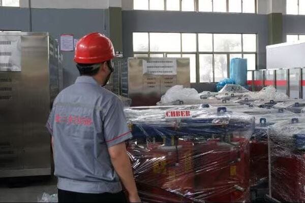
Analyzing the Diagram Misalignment Incident
Let’s break down this case study to understand what went wrong and how it could have been prevented:
- Project Background
- Key Issues Encountered
- Consequences of Misalignment
- Resolution Process
- Lessons Learned and Best Practices
Project Background
The project involved exporting a large power transformer from a European manufacturer to a US utility company:
- Transformer Rating: 100 MVA, 230kV/69kV
- Manufacturer: Based in Germany, typically using IEC standards
- Client: Major US utility company, familiar with ANSI standards
- Project Timeline: 18 months from order to planned commissioning
I was brought in as a consultant when issues started arising during the installation phase. The complexity of translating between IEC and ANSI standards became immediately apparent.
Key Issues Encountered
Several problems emerged due to diagram misalignment:
-
Protection Device Misinterpretation:
- IEC symbols for Buchholz relay and pressure relief devices were misunderstood
- US team incorrectly assumed functionalities based on ANSI symbol expectations
-
Winding Configuration Confusion:
- IEC winding notation led to misunderstanding of the transformer’s vector group
- Resulted in incorrect phasing during initial connection attempts
-
Tap Changer Representation:
- IEC-style tap changer diagram caused confusion about operating mechanisms
- Led to improper integration with the utility’s control systems
-
Bushing Terminal Labeling:
- IEC’s numerical system (1U, 1V, 1W) vs. ANSI’s letter system (H1, H2, H3) caused connection errors
During the initial installation attempt, I witnessed the confusion firsthand as the US team struggled to reconcile the IEC diagrams with their ANSI-based expectations.
Consequences of Misalignment
The diagram misalignment led to several serious issues:
-
Installation Delays:
- Project faced a two-week delay for diagram conversion and correction
- Knock-on effects on other scheduled maintenance works
-
Additional Costs:
- On-site engineering support required for diagram interpretation
- Rework of some connections and control wiring
- Expedited shipping for correct components
-
Safety Concerns:
- Potential for equipment damage due to incorrect connections
- Near-miss incident due to misunderstanding of protection schemes
-
Strained Client Relationships:
- Loss of confidence from the US utility company
- Increased scrutiny on future projects
The project manager estimated that these issues increased the overall project cost by approximately 15%, a significant overrun that could have been avoided.
Resolution Process
To resolve the issues, several steps were taken:
-
Emergency On-Site Support:
- Manufacturer sent IEC experts to collaborate with US team
- I facilitated daily workshops to bridge the knowledge gap
-
Comprehensive Diagram Conversion:
- All IEC diagrams were converted to ANSI format
- Created side-by-side comparisons for critical components
-
Revised Testing Procedures:
- Implemented additional testing phases to verify correct connections
- Developed new checklists incorporating both IEC and ANSI terminologies
-
Enhanced Communication Protocols:
- Established clear channels for technical queries
- Implemented daily cross-team meetings to address emerging issues
-
Documentation Overhaul:
- Created a comprehensive cross-reference guide for future projects
- Updated all project documents to include dual-standard notations
Lessons Learned and Best Practices
This case study highlighted several key learnings:
-
Proactive Standard Alignment:
- Identify and address standard differences at the project’s outset
- Consider creating dual-standard documentation for critical components
-
Enhanced Training:
- Provide cross-training on IEC and ANSI standards for key personnel
- Develop in-house expertise in standard conversion
-
Improved Communication:
- Clearly specify the applicable standards in all project documentation
- Establish protocols for addressing standard-related queries
-
Quality Control Measures:
- Implement additional review stages for diagram accuracy
- Conduct mock installations using provided diagrams before shipping
-
Client Engagement:
- Involve the client in early discussions about standards and expectations
- Provide educational materials on standard differences if necessary
In retrospect, this project served as a valuable lesson in the importance of standards alignment in international transformer projects. By implementing these lessons learned, we’ve significantly improved our approach to export projects, reducing risks and enhancing client satisfaction.
Remember, in the global power industry, understanding and effectively managing diagram standards is not just a technical necessity—it’s a crucial factor in project success and building long-term international partnerships.
Summary: Diagram Standard Choice Impacts Project Success?
Are you aware of how significantly your choice of transformer diagram standard can impact your project’s overall success? Many professionals underestimate the far-reaching effects of this seemingly technical decision. But how exactly does the selection between IEC and ANSI standards influence project outcomes, costs, and efficiency?
Choosing the appropriate transformer diagram standard (IEC or ANSI) is crucial for project success. It affects communication clarity, regulatory compliance, installation efficiency, and overall project costs. Using the wrong standard can lead to misinterpretations, delays, and expensive rework. Proper standard selection and management ensure smooth execution, especially in international projects, ultimately impacting project timelines, budgets, and stakeholder satisfaction.
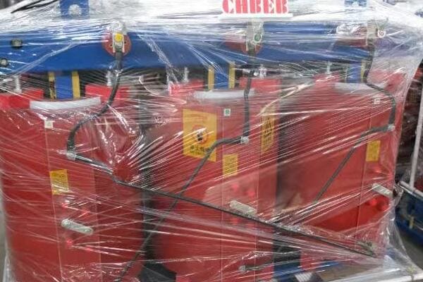
The Ripple Effect of Diagram Standard Selection
Let’s explore how diagram standard choice influences key project aspects:
- Communication and Interpretation
- Regulatory Compliance and Approval
- Installation and Commissioning Efficiency
- Project Costs and Timelines
- Long-term Operational Impacts
Communication and Interpretation
The choice of standard directly affects how information is conveyed and understood:
- Mismatched standards can lead to misinterpretation of critical components
- Consistent standards enhance clarity in team communications
- Proper standard selection facilitates smoother international collaborations
I recall a project where using IEC diagrams in an ANSI-dominated market led to significant communication barriers. We had to invest additional time in creating interpretation guides, which could have been avoided with the right standard choice from the start.
Regulatory Compliance and Approval
Standard selection impacts the regulatory process:
- Using the region’s preferred standard can expedite approvals
- Misaligned standards may require additional documentation or reviews
- Some markets mandate specific standards for compliance
During a recent export project to North America, our initial use of IEC diagrams led to delays in regulatory approval. Switching to ANSI-compliant diagrams significantly streamlined the process.
Installation and Commissioning Efficiency
The right standard choice can greatly affect on-site efficiency:
- Familiar standards reduce installation time and errors
- Mismatched standards may require on-site interpretation, causing delays
- Proper standard selection ensures smoother integration with existing systems
I’ve witnessed how using the correct diagram standard can shave days off installation timelines, particularly in complex transformer projects where every connection counts.
Project Costs and Timelines
Standard selection has direct financial implications:
- Correct standards from the outset reduce the need for costly revisions
- Misaligned standards can lead to expensive rework and delays
- Proper selection can prevent the need for additional on-site technical support
Here’s a quick comparison of potential impacts:
| Aspect | Correct Standard Choice | Misaligned Standard |
|---|---|---|
| Timeline | As planned | Potential delays |
| Installation Costs | Within budget | Risk of overruns |
| Regulatory Approval | Streamlined | May require revisions |
| Team Efficiency | High | Reduced due to confusion |
Long-term Operational Impacts
The choice of standard can have lasting effects:
- Consistent standards simplify future maintenance and upgrades
- Mismatched standards may complicate spare parts management
- Proper selection ensures easier integration with future expansions
In a recent long-term power system upgrade project, consistently using ANSI standards across all phases ensured seamless integration of new equipment over a five-year period.
Key considerations for maximizing project success through proper standard selection:
-
Assess the Project Context:
- Understand the geographical and regulatory environment
- Consider the standards familiar to the end-user and maintenance teams
-
Plan for Standard Alignment Early:
- Address standard choices in the initial project planning phases
- Budget for potential standard conversion if necessary
-
Enhance Team Capabilities:
- Invest in training for both IEC and ANSI standards
- Develop in-house expertise in standard conversion and interpretation
-
Improve Documentation Practices:
- Clearly specify standards used in all project documents
- Consider dual-standard documentation for critical components
-
Engage Stakeholders:
- Discuss standard preferences with clients and regulators early
- Educate stakeholders on the implications of standard choices
In my experience, projects that carefully consider and manage diagram standards tend to run more smoothly, encounter fewer costly surprises, and achieve higher client satisfaction. I’ve seen how this approach not only improves immediate project outcomes but also enhances long-term operational efficiency and ease of maintenance.
Remember, the impact of your diagram standard choice extends far beyond the technical realm. It influences communication, compliance, efficiency, and ultimately, the overall success of your transformer projects. By carefully considering standard selection and implementing best practices in standard management, you can significantly improve your project outcomes and build a reputation for reliability in the global power industry.
Conclusion
Understanding and correctly applying IEC and ANSI standards for transformer diagrams is crucial for project success. Proper standard selection enhances communication, ensures compliance, improves efficiency, and reduces costs. Always consider the project’s context, plan early for standard alignment, and invest in team training to navigate these standards effectively in global transformer projects.
Are you struggling to choose the right transformer diagram for your project? You’re not alone. Many engineers and technicians find themselves confused about when to use single-line diagrams versus wiring diagrams. But what if you could easily determine which diagram type is best suited for your specific needs?
Single-line diagrams show simplified power flow with major components, ideal for quick system planning. Wiring diagrams detail every electrical connection, crucial for installation and troubleshooting. Understanding when to use each helps technicians, engineers, and buyers avoid costly mistakes in transformer applications.
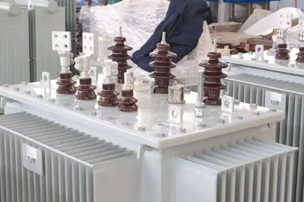
In this comprehensive guide, I’ll walk you through the key differences between single-line and wiring transformer diagrams, and provide you with practical insights to help you make the right choice for your project. Whether you’re working on a large-scale utility project or a local power distribution system, this article will equip you with the knowledge to select the optimal diagram type for your needs.
Introduction – Why Diagram Types Matter in Transformer Projects?
Have you ever wondered why there are different types of transformer diagrams? The choice between a single-line diagram and a wiring diagram can significantly impact your project’s success. But why does this matter, and how can it affect your work?
Choosing the right diagram type is crucial for effective communication, accurate planning, and successful implementation of transformer projects. Single-line diagrams provide a quick overview for system planning, while wiring diagrams offer detailed information for installation and troubleshooting. Using the wrong type can lead to misunderstandings, errors, and costly delays.
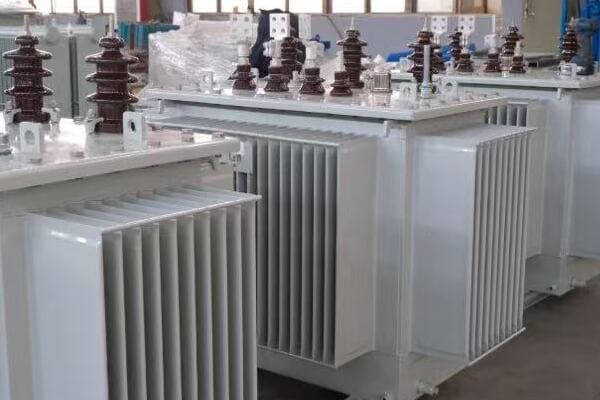
The Importance of Proper Diagram Selection
Let’s explore why choosing the right diagram type is so critical:
- Communication Clarity
- Project Phase Alignment
- Cost and Time Efficiency
- Safety and Compliance
Communication Clarity
Different diagrams serve different purposes in communicating system information:
- Single-line diagrams: Provide a clear, high-level view of the system
- Wiring diagrams: Offer detailed connection information
I once worked on a project where miscommunication between the design team and installers occurred due to reliance on single-line diagrams alone. This led to confusion during installation, highlighting the need for both diagram types at different project stages.
Project Phase Alignment
Each project phase requires specific information:
- Planning and conceptual design: Single-line diagrams are ideal
- Detailed design and installation: Wiring diagrams become crucial
During a recent substation upgrade, we used single-line diagrams for initial stakeholder presentations and switched to detailed wiring diagrams for the installation phase. This approach ensured everyone had the right level of information at each stage.
Cost and Time Efficiency
Using the appropriate diagram can save significant time and resources:
- Single-line diagrams: Quick to create and review, perfect for early-stage decisions
- Wiring diagrams: Time-consuming but essential for accurate installation and maintenance
I recall a situation where a contractor attempted to use only single-line diagrams for a complex installation. This resulted in numerous on-site queries and delays, ultimately increasing project costs.
Safety and Compliance
Proper diagram use is crucial for safety and regulatory compliance:
- Single-line diagrams: Often required for permit applications and high-level safety reviews
- Wiring diagrams: Essential for detailed safety checks and compliance with electrical codes
In a recent industrial project, having both diagram types available during a safety audit helped us quickly address inspector concerns at both system and component levels.
Here’s a quick reference table for diagram type importance:
| Aspect | Single-Line Diagram | Wiring Diagram |
|---|---|---|
| Overview | Excellent | Limited |
| Detail Level | Low | High |
| Design Phase | Early | Late |
| Installation Use | Limited | Essential |
| Safety Review | High-level | Detailed |
Understanding the importance of proper diagram selection is the first step in ensuring your transformer projects run smoothly. As we delve deeper into the specifics of each diagram type, keep in mind how their unique characteristics align with different project needs and phases.
Remember, the goal is not just to have a diagram, but to have the right diagram at the right time. This understanding will guide you in making informed decisions throughout your transformer projects, ultimately leading to more efficient, safe, and successful outcomes.
What Is a Single-Line Transformer Diagram?
Have you ever been overwhelmed by the complexity of electrical system layouts? Single-line transformer diagrams offer a solution to this problem, but what exactly are they, and how do they simplify complex systems?
A single-line transformer diagram is a simplified representation of a power system, showing major components like transformers, switches, and buses using single lines and standard symbols. It provides a clear overview of power flow and system structure without the clutter of detailed connections, making it ideal for high-level planning and quick system understanding.
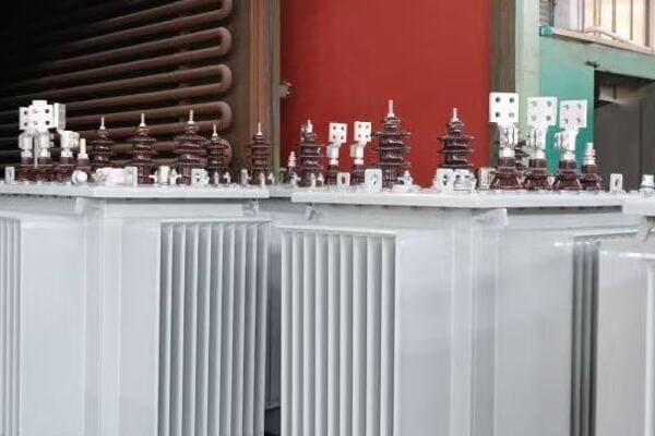
Understanding Single-Line Transformer Diagrams
Let’s break down the key aspects of single-line diagrams:
- Key Components and Notation
- Purpose and Benefits
- Limitations and Considerations
Key Components and Notation
Single-line diagrams use standardized symbols to represent:
- Transformers: Usually shown as circles with lines inside
- Circuit breakers: Represented by a square with a zigzag line
- Disconnectors: Often depicted as a small gap in the line
- Buses: Shown as thick horizontal or vertical lines
I remember a project where a client was initially confused by the symbols. After explaining the notation, they appreciated how quickly they could grasp the overall system layout.
Purpose and Benefits
The main advantages of single-line diagrams include:
- Quick system overview: Ideal for management presentations and initial planning
- Simplified troubleshooting: Helps identify major components and their relationships
- Easy modification: Allows for quick changes during conceptual design phases
During a recent utility-scale project, we used a single-line diagram to quickly illustrate different system configurations to stakeholders. This visual aid significantly streamlined the decision-making process.
Limitations and Considerations
While powerful, single-line diagrams have limitations:
- Lack of detailed connections: Not suitable for installation or detailed troubleshooting
- Simplified representation: May omit some important system details
- Potential for misinterpretation: Users must understand the diagram’s purpose and limitations
I once encountered a situation where an installer tried to use only a single-line diagram for a complex transformer installation. This led to confusion and delays, highlighting the need for more detailed diagrams in certain phases.
Here’s a quick reference table for single-line diagram characteristics:
| Aspect | Description | Importance |
|---|---|---|
| Simplicity | High-level view | Essential for quick understanding |
| Detail Level | Low | Limits use in detailed work |
| Modification Ease | High | Valuable in early design stages |
| Component Representation | Symbolic | Requires familiarity with symbols |
Best use cases for single-line transformer diagrams include:
- System planning and conceptual design
- High-level presentations to management or non-technical stakeholders
- Quick fault analysis and system navigation
- Regulatory submissions requiring overall system layouts
In my experience, the key to effectively using single-line diagrams is understanding their strengths and limitations. They excel at providing a "big picture" view but should be complemented with more detailed diagrams when moving into implementation phases.
As we move forward, we’ll explore how single-line diagrams compare to wiring diagrams, and when each is most appropriate. Understanding these differences will help you choose the right diagram type for each stage of your transformer projects, ensuring clear communication and efficient project execution.
What Is a Wiring Transformer Diagram?
Have you ever found yourself needing to trace every connection in a transformer system? While single-line diagrams provide a high-level overview, wiring diagrams offer the detailed information necessary for installation and troubleshooting. But what exactly is a wiring transformer diagram, and how does it differ from its simplified counterpart?
A wiring transformer diagram is a detailed electrical schematic that shows every connection, wire, and component in a transformer system. It includes specific information on terminal connections, wire gauges, and control circuits. These diagrams are essential for installation, maintenance, and troubleshooting, providing technicians with the precise information needed to work on complex transformer systems.

Diving Deep into Wiring Transformer Diagrams
Let’s explore the key aspects of wiring diagrams:
- Detailed Connection Mapping
- Component Representation
- Applications and Benefits
- Challenges in Creation and Interpretation
Detailed Connection Mapping
Wiring diagrams provide comprehensive connection information:
- Every wire and connection point is shown
- Wire gauges and types are specified
- Terminal block layouts are detailed
- Control circuits and auxiliary devices are included
I recall a complex industrial transformer installation where the wiring diagram was invaluable. It allowed us to precisely trace each connection, ensuring no errors were made during the intricate wiring process.
Component Representation
Wiring diagrams offer detailed representations of components:
- Transformers: Shown with all windings and taps
- Circuit breakers: Depicted with all poles and auxiliary contacts
- Relays and controls: Illustrated with all coils and contacts
- Instruments: Represented with their connections and scaling information
During a recent troubleshooting session, the detailed representation of a malfunctioning relay in the wiring diagram helped us quickly identify and resolve the issue, saving hours of downtime.
Applications and Benefits
Wiring diagrams are crucial for several aspects of transformer work:
- Installation: Provides exact connection information for technicians
- Troubleshooting: Allows for precise tracing of electrical paths
- Maintenance: Helps in understanding system intricacies for repairs
- Modifications: Essential for planning and implementing system changes
I once worked on upgrading an old transformer system where the original wiring diagram was invaluable. It allowed us to understand the existing setup and plan the upgrade with minimal disruption.
Challenges in Creation and Interpretation
While highly useful, wiring diagrams come with challenges:
- Time-consuming to create: Requires detailed knowledge of the entire system
- Complex to read: Can be overwhelming for those not familiar with electrical schematics
- Requires regular updates: Must be revised with any system changes
In a recent project, we faced issues with an outdated wiring diagram. This experience highlighted the importance of maintaining up-to-date documentation for all transformer systems.
Here’s a quick reference table for wiring diagram characteristics:
| Aspect | Description | Importance |
|---|---|---|
| Detail Level | Very High | Critical for precise work |
| Creation Time | Lengthy | Significant investment |
| Usability in Field | High | Essential for technicians |
| Modification Difficulty | Moderate to High | Requires careful updating |
Best use cases for wiring transformer diagrams include:
- Detailed installation and assembly work
- Comprehensive system troubleshooting
- Planning and executing system modifications
- Training technicians on specific system layouts
In my experience, the key to effectively using wiring diagrams is to ensure they are always up-to-date and accessible to those who need them. While they require more effort to create and maintain than single-line diagrams, their value in complex transformer work is unparalleled.
As we continue, we’ll compare wiring diagrams directly with single-line diagrams, helping you understand when to use each type. This knowledge is crucial for ensuring you have the right information at the right time throughout your transformer projects.
Key Differences Between Single-Line and Wiring Diagrams?
Are you finding it challenging to decide between using a single-line diagram or a wiring diagram for your transformer project? You’re not alone. Many professionals struggle to understand the key differences and when to use each type. But what if you had a clear comparison to guide your decision?
Single-line diagrams provide a simplified overview of the power system, ideal for high-level planning and quick understanding. Wiring diagrams offer detailed connection information, crucial for installation and troubleshooting. The main differences lie in their level of detail, purpose, and application in various project phases. Understanding these differences is key to choosing the right diagram for your specific needs.
Comparing Single-Line and Wiring Diagrams
Let’s break down the key differences:
- Level of Detail
- Purpose and Application
- Creation and Maintenance
- User Audience
Level of Detail
The most obvious difference lies in the amount of information presented:
| Feature | Single-Line Diagram | Wiring Diagram |
|---|---|---|
| Complexity | Low | High |
| Component Representation | Symbolic | Detailed |
| Connection Details | Minimal | Comprehensive |
| System Overview | Clear | Can be overwhelming |
I once worked on a project where the client was initially confused by the wiring diagram’s complexity. Showing them the single-line diagram first helped them grasp the overall system before diving into the details.
Purpose and Application
Each diagram type serves different purposes:
| Aspect | Single-Line Diagram | Wiring Diagram |
|---|---|---|
| Primary Use | System planning, conceptual design | Installation, troubleshooting |
| Project Phase | Early stages, high-level reviews | Detailed design, implementation |
| Fault Analysis | Quick, high-level | Detailed, component-level |
| Regulatory Submissions | Often sufficient | May be required for detailed reviews |
During a recent substation upgrade, we used single-line diagrams for initial planning and stakeholder presentations, then transitioned to wiring diagrams for the actual installation phase. This approach ensured everyone had the right level of information at each stage.
Creation and Maintenance
The effort required to create and maintain these diagrams differs significantly:
| Factor | Single-Line Diagram | Wiring Diagram |
|---|---|---|
| Creation Time | Relatively quick | Time-consuming |
| Updating Ease | Simple | Complex |
| Software Requirements | Basic CAD or drawing tools | Specialized electrical CAD software |
| Version Control Importance | Moderate | Critical |
I recall a situation where an outdated wiring diagram led to confusion during a maintenance operation. This experience highlighted the importance of rigorous version control, especially for detailed wiring diagrams.
User Audience
Different diagrams cater to different audiences:
| Audience | Single-Line Diagram | Wiring Diagram |
|---|---|---|
| Management | Preferred | Often too detailed |
| Engineers | Used for overview | Used for detailed work |
| Technicians | Limited use | Essential |
| Regulatory Bodies | Often sufficient | May be required for detailed review |
In a recent project presentation, I observed how single-line diagrams effectively communicated the system layout to executive stakeholders, while the engineering team relied heavily on the wiring diagrams for implementation details.
Key considerations when choosing between diagram types:
- Project Phase: Early planning favors single-line diagrams, while detailed design and implementation require wiring diagrams.
- Audience: Consider who will be using the diagram and for what purpose.
- Level of Detail Needed: Assess whether a high-level overview or detailed connection information is required.
- Time and Resources: Factor in the time and expertise needed to create and maintain each diagram type.
In my experience, the most successful projects use both diagram types at appropriate stages. Starting with a single-line diagram helps establish a clear overall vision, while transitioning to wiring diagrams ensures precise implementation.
Remember, the goal is not to choose one diagram type over the other, but to use each type effectively at the right time and for the right purpose. By understanding these key differences, you can ensure that your transformer projects benefit from clear communication and accurate information at every stage.
When to Use Each Type of Diagram?
Are you unsure about which transformer diagram to use in different project scenarios? This common dilemma can lead to miscommunication and errors if not addressed properly. But how can you confidently choose the right diagram type for each situation in your transformer projects?
Use single-line diagrams for high-level planning, system overviews, and conceptual designs. They’re ideal for management presentations and initial stakeholder discussions. Wiring diagrams are essential for detailed design, installation, troubleshooting, and maintenance. Choose based on your project phase, audience, and the level of detail required. Using the right diagram at the right time ensures effective communication and project success.
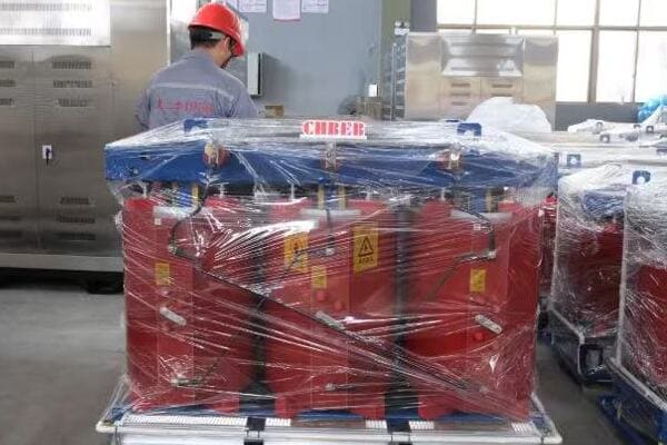
Choosing the Right Diagram for Your Project Phase
Let’s explore when to use each diagram type across different project scenarios:
- Conceptual Design and Planning
- Detailed Engineering and Design
- Installation and Construction
- Operation and Maintenance
- Troubleshooting and Repairs
Conceptual Design and Planning
At this early stage, single-line diagrams are typically the best choice:
- Provide a clear system overview
- Facilitate high-level decision making
- Useful for initial stakeholder presentations
I remember a utility-scale project where we used a single-line diagram to present different system configurations to the board of directors. The simplicity of the diagram allowed for quick understanding and faster decision-making on the overall project direction.
Detailed Engineering and Design
As the project progresses, wiring diagrams become crucial:
- Essential for detailed component selection
- Necessary for precise connection planning
- Required for comprehensive design reviews
During a recent transformer upgrade project, transitioning from single-line to wiring diagrams allowed our engineering team to identify potential issues with control circuit integration that weren’t apparent in the simplified view.
Installation and Construction
At this stage, both diagram types play important roles:
- Single-line diagrams: Provide overall guidance and context
- Wiring diagrams: Essential for accurate installation and connections
I once witnessed a installation delay caused by reliance on single-line diagrams alone. The team quickly realized they needed the detailed wiring diagrams to properly connect all components, highlighting the importance of having both diagram types available during this phase.
Operation and Maintenance
For day-to-day operations and routine maintenance:
- Single-line diagrams: Useful for quick system navigation and understanding
- Wiring diagrams: Critical for detailed maintenance procedures and troubleshooting
In a recent maintenance training session, we used single-line diagrams to explain system layout to new technicians, then delved into wiring diagrams for specific maintenance tasks. This approach significantly improved the team’s overall understanding and efficiency.
Troubleshooting and Repairs
When issues arise, both diagram types become valuable:
- Single-line diagrams: Help in quickly identifying the affected area
- Wiring diagrams: Essential for pinpointing exact fault locations and planning repairs
I recall a critical fault scenario where we first used the single-line diagram to isolate the problem area, then relied on the wiring diagram to trace the exact fault location. This two-step approach significantly reduced downtime.
Here’s a quick reference table for when to use each diagram type:
| Project Phase | Single-Line Diagram | Wiring Diagram |
|---|---|---|
| Conceptual Design | Primary tool | Not typically used |
| Detailed Engineering | Supplementary | Primary tool |
| Installation | Context provider | Essential guide |
| Operation | Quick reference | Detailed resource |
| Troubleshooting | Initial assessment | Detailed analysis |
Key considerations for choosing the right diagram:
-
Audience Knowledge: Consider the technical expertise of your audience. Management might prefer single-line diagrams, while technicians need wiring diagrams.
-
Project Complexity: More complex systems may require earlier introduction of wiring diagrams in the project lifecycle.
-
Regulatory Requirements: Some phases may legally require specific diagram types. Always check relevant standards and regulations.
-
Time Constraints: In time-sensitive situations, single-line diagrams can provide quick insights, but don’t neglect wiring diagrams for critical details.
-
Communication Purpose: Determine whether you need to convey an overall concept (single-line) or specific details (wiring).
In my experience, the most successful projects maintain both diagram types throughout the project lifecycle, using each at appropriate times. I’ve seen projects stumble when they relied too heavily on one type, missing critical insights that the other could provide.
Remember, the goal is to ensure clear communication and accurate information at every project stage. By carefully considering your current needs and audience, you can choose the right diagram type to support your project’s success. As you move through different phases, be prepared to switch between diagram types as needed, always ensuring you have the right level of detail for the task at hand.
Real Project Examples: Diagram Misuse & Lessons Learned?
Have you ever wondered about the real-world consequences of using the wrong type of transformer diagram? Many professionals have faced challenges due to diagram misuse, but what can we learn from these experiences to avoid similar pitfalls in our own projects?
Misusing transformer diagrams can lead to costly errors, safety hazards, and project delays. Common mistakes include relying solely on single-line diagrams for installation or using outdated wiring diagrams for modifications. These errors can result in incorrect connections, equipment damage, and even system failures. Learning from these real-world examples helps prevent similar issues in future projects.
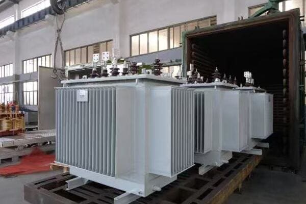
Case Studies: When Diagram Choice Goes Wrong
Let’s explore some real project examples and the valuable lessons they teach:
- Installation Errors Due to Diagram Misuse
- Safety Incidents from Incomplete Information
- Project Delays Caused by Diagram Confusion
- Cost Overruns from Rework
Case 1: Installation Errors Due to Diagram Misuse
Scenario: A substation upgrade project relied solely on single-line diagrams for installation.
Outcome: Multiple wiring errors led to equipment malfunction during commissioning.
Lesson Learned: Always use detailed wiring diagrams for installation work, even if single-line diagrams are available for overview.
I was called in as a consultant on this project after the issues were discovered. The team had assumed the single-line diagram provided sufficient information, not realizing the critical details they were missing. We had to spend additional time and resources correcting the wiring, significantly delaying the project completion.
Case 2: Safety Incidents from Incomplete Information
Scenario: Maintenance team used an outdated wiring diagram for troubleshooting a transformer.
Outcome: A technician received an electric shock due to an undocumented circuit modification.
Lesson Learned: Maintain up-to-date wiring diagrams and ensure all modifications are promptly documented.
This incident highlighted the critical importance of diagram accuracy and version control. We implemented a new system for updating and distributing the latest diagram versions to all relevant personnel, significantly improving safety protocols.
Case 3: Project Delays Caused by Diagram Confusion
Scenario: Engineering team provided only complex wiring diagrams to stakeholders for approval.
Outcome: Confusion and multiple revision requests delayed project kickoff by several weeks.
Lesson Learned: Use single-line diagrams for initial stakeholder communications, then progress to detailed wiring diagrams as needed.
I was part of the review team for this project. The complexity of the wiring diagrams overwhelmed non-technical stakeholders, leading to unnecessary questions and delays. We later introduced simplified single-line diagrams, which greatly improved understanding and accelerated the approval process.
Case 4: Cost Overruns from Rework
Scenario: Contractor used single-line diagrams for material procurement in a large transformer project.
Outcome: Incorrect cable types and quantities were ordered, requiring expensive rush orders and rework.
Lesson Learned: Always refer to detailed wiring diagrams for specific material and equipment requirements.
This case taught us the importance of using the right diagram for the right purpose. The project manager now insists on reviewing both single-line and wiring diagrams before finalizing any major procurement decisions.
Here’s a summary table of these case studies:
| Case | Diagram Misuse | Consequence | Key Lesson |
|---|---|---|---|
| Installation Error | Single-line only | Equipment malfunction | Use wiring diagrams for installation |
| Safety Incident | Outdated wiring diagram | Electric shock | Keep diagrams updated |
| Project Delay | Complex wiring diagrams only | Stakeholder confusion | Start with single-line for overview |
| Cost Overrun | Single-line for procurement | Incorrect materials | Use wiring diagrams for specifics |
Key takeaways from these real-world examples:
- Always use the appropriate diagram type for the task at hand.
- Maintain and update both single-line and wiring diagrams throughout the project lifecycle.
- Consider your audience when presenting diagrams, and choose the type that best communicates your message.
- Implement a robust system for diagram version control and distribution.
- Train team members on the proper use and interpretation of both diagram types.
In my experience, these lessons have proven invaluable in preventing similar issues in subsequent projects. By sharing these experiences, I hope to help others avoid the pitfalls of diagram misuse and improve overall project outcomes.
Remember, the choice between single-line and wiring diagrams isn’t just a technical decision – it’s a critical factor in project success, safety, and efficiency. By learning from these real-world examples, we can make more informed choices and ensure our transformer projects run smoothly from conception to completion.
Summary: Diagram Choice Affects Cost, Safety, and Efficiency?
Are you aware of how significantly your choice of transformer diagram can impact your project’s bottom line, safety record, and overall efficiency? Many professionals underestimate the far-reaching effects of this seemingly simple decision. But how exactly does diagram selection influence these crucial aspects of transformer projects?
Choosing the right transformer diagram type directly affects project costs, safety measures, and operational efficiency. Single-line diagrams support quick decision-making and overview, potentially saving time in planning stages. Wiring diagrams ensure accurate installation and maintenance, reducing costly errors and safety risks. Using both types appropriately throughout a project lifecycle optimizes resource allocation, enhances safety protocols, and improves overall system reliability.

The Ripple Effect of Diagram Selection
Let’s explore how diagram choice influences key project aspects:
- Cost Implications
- Safety Considerations
- Efficiency and Performance
- Long-term Maintenance and Operations
Cost Implications
Proper diagram selection can significantly impact project costs:
- Planning Phase: Single-line diagrams facilitate faster decision-making, potentially reducing planning costs.
- Installation: Accurate wiring diagrams prevent costly installation errors and rework.
- Procurement: Detailed wiring diagrams ensure correct material ordering, avoiding expensive rush orders or surplus inventory.
I recall a project where reliance on single-line diagrams for material procurement led to significant cost overruns. The lack of detailed information resulted in incorrect cable specifications, requiring last-minute purchases at premium prices.
Safety Considerations
Diagram choice plays a crucial role in maintaining safety:
- Risk Assessment: Single-line diagrams help identify high-level safety concerns quickly.
- Maintenance Safety: Detailed wiring diagrams are essential for safe maintenance procedures.
- Emergency Response: Both diagram types are crucial for effective emergency planning and response.
During a recent safety audit, having both single-line and wiring diagrams readily available allowed us to demonstrate comprehensive safety protocols, from system-level hazard identification to detailed lockout/tagout procedures.
Efficiency and Performance
The right diagrams can enhance overall system efficiency:
- System Optimization: Single-line diagrams aid in identifying potential system improvements.
- Troubleshooting: Wiring diagrams significantly reduce downtime during fault diagnosis.
- Upgrades and Modifications: Accurate diagrams of both types facilitate smoother system upgrades.
I’ve seen how efficient troubleshooting with proper wiring diagrams can reduce downtime from days to hours, significantly impacting operational efficiency and cost savings.
Long-term Maintenance and Operations
Diagram choice affects long-term operational aspects:
- Training: Single-line diagrams are excellent for new staff orientation.
- Maintenance Planning: Wiring diagrams are crucial for developing comprehensive maintenance schedules.
- Asset Management: Both diagram types contribute to effective long-term asset management strategies.
In a recent transformer fleet management project, maintaining updated versions of both diagram types allowed for more effective lifecycle planning and predictive maintenance strategies.
Here’s a summary table of how diagram choice impacts various project aspects:
| Aspect | Single-Line Diagram Impact | Wiring Diagram Impact |
|---|---|---|
| Cost | Reduces planning time | Prevents installation errors |
| Safety | Aids high-level risk assessment | Ensures safe maintenance |
| Efficiency | Supports system optimization | Facilitates quick troubleshooting |
| Long-term Operations | Useful for staff training | Essential for detailed maintenance |
Key considerations for maximizing the benefits of proper diagram selection:
- Integrate Both Types: Use single-line and wiring diagrams in tandem throughout the project lifecycle.
- Update Regularly: Keep both diagram types current to ensure ongoing relevance and safety.
- Accessibility: Ensure relevant team members have access to the appropriate diagrams when needed.
- Training: Invest in training staff on how to read and use both diagram types effectively.
- Digital Integration: Consider integrating diagrams into digital asset management systems for easier updates and access.
In my experience, projects that strategically use both single-line and wiring diagrams throughout their lifecycle tend to run more smoothly, encounter fewer costly surprises, and maintain better safety records. I’ve seen how this approach not only improves immediate project outcomes but also enhances long-term operational efficiency and asset management.
Remember, the impact of your diagram choice extends far beyond the immediate project phase. By carefully considering when and how to use each type of diagram, you can positively influence your project’s cost-effectiveness, safety standards, and overall efficiency. This strategic approach to diagram selection is a key factor in achieving successful, sustainable transformer projects that stand the test of time.
Conclusion
Choosing between single-line and wiring transformer diagrams significantly impacts project success. Single-line diagrams excel in planning and overview, while wiring diagrams are crucial for detailed work and safety. Using both types appropriately throughout a project’s lifecycle optimizes costs, enhances safety, and improves efficiency. Always consider your project phase and audience when selecting diagram types.
Remember, at chbeb-ele, we’re not just sharing information – we’re empowering you to be part of the solution in creating a secure, clean, and efficient energy future. Let’s continue this journey together.
Are you struggling to make sense of complex distribution transformer diagrams? You’re not alone. Many technicians find these schematics confusing, leading to costly mistakes and safety risks. But what if you could confidently interpret these diagrams, improving your efficiency and reducing errors on the job?
Distribution transformer diagrams show how electricity flows through transformer components like windings, terminals, and grounding points. Technicians use these diagrams to install, inspect, or troubleshoot transformers. This step-by-step guide explains key symbols and layout rules to help you interpret wiring and schematic diagrams with confidence.

In this comprehensive guide, I’ll walk you through the process of reading distribution transformer diagrams, from understanding basic symbols to interpreting complex schematics. Whether you’re a novice technician or an experienced professional looking to refine your skills, this article will provide you with the knowledge to tackle transformer diagrams with confidence.
What Is a Distribution Transformer Diagram?
Have you ever wondered why distribution transformer diagrams look so complex? These intricate drawings serve a crucial purpose, but their complexity can be overwhelming. So, what exactly are these diagrams, and why are they so important for technicians?
A distribution transformer diagram is a technical drawing that illustrates the internal connections, components, and electrical pathways of a transformer. It includes wiring schematics, connection points, and component layouts. These diagrams are essential for installation, maintenance, and troubleshooting, providing technicians with a detailed map of the transformer’s electrical system.
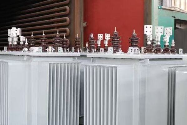
Understanding Different Types of Transformer Diagrams
Let’s explore the main types of diagrams you’ll encounter:
- Single-Line Diagrams
- Wiring Schematics
- Connection Diagrams
- Nameplate Information
Single-Line Diagrams
Single-line diagrams provide a simplified overview of the transformer’s electrical system:
- Show main power flow paths
- Use simplified symbols for components
- Ideal for quick system understanding
I once used a single-line diagram to quickly diagnose a power distribution issue in a large industrial complex. The simplicity of the diagram allowed me to trace the problem to a specific transformer in minutes, saving hours of troubleshooting time.
Wiring Schematics
Wiring schematics offer detailed representations of electrical connections:
- Show all electrical components and connections
- Include control circuits and protection devices
- Essential for detailed troubleshooting and repairs
During a recent transformer upgrade project, the wiring schematic was crucial in identifying an incorrectly wired control circuit that could have caused significant operational issues if left undetected.
Connection Diagrams
Connection diagrams focus on the physical layout of components:
- Illustrate physical arrangement of terminals and bushings
- Show how external connections should be made
- Vital for proper installation and maintenance
I recall a situation where a misinterpreted connection diagram led to an incorrectly installed transformer. By carefully reviewing the diagram with the installation team, we were able to correct the error before energizing the system, potentially preventing a dangerous situation.
Nameplate Information
While not a diagram per se, the nameplate provides critical information:
- Includes voltage ratings, capacity, impedance, and vector group
- Often contains a simplified connection diagram
- Essential for verifying transformer specifications
Here’s a quick reference table for the types of information found on transformer diagrams:
| Diagram Type | Key Information | Primary Use |
|---|---|---|
| Single-Line | Overall system layout | System planning |
| Wiring Schematic | Detailed electrical connections | Troubleshooting |
| Connection Diagram | Physical component layout | Installation |
| Nameplate | Specifications and ratings | Verification |
Understanding these different types of diagrams is crucial for effective transformer management. Each serves a specific purpose and provides unique insights into the transformer’s design and operation.
In my experience, the ability to quickly identify and interpret the correct type of diagram for a given task is a hallmark of an efficient technician. I’ve seen many situations where referring to the wrong type of diagram led to confusion and errors. For instance, trying to use a single-line diagram for detailed wiring troubleshooting can be frustrating and ineffective.
As we delve deeper into the specifics of reading these diagrams, remember that each type has its place in your toolkit. Knowing when and how to use each type of diagram will significantly enhance your ability to work with distribution transformers effectively and safely.
Understanding Transformer Symbols and Labels
Are you finding yourself puzzled by the array of symbols and labels on transformer schematics? You’re not alone. Many technicians struggle to decipher these critical elements. But what if you had a clear guide to help you understand each symbol and its significance?
Transformer schematics use standardized symbols to represent components like windings, bushings, and taps. Key labels include voltage ratings, winding connections (e.g., Delta or Wye), and terminal markings. Understanding these symbols and labels is crucial for correctly interpreting the transformer’s configuration and connections, ensuring proper installation and maintenance.
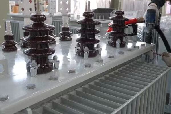
Essential Symbols and Labels in Transformer Diagrams
Let’s break down the most important symbols and labels you’ll encounter:
- Winding Representations
- Bushing and Terminal Symbols
- Connection Type Indicators
- Tap Changer Symbols
- Protective Device Symbols
Winding Representations
Windings are the heart of a transformer and are represented in specific ways:
- Primary windings: Often shown as thicker lines or on the left side
- Secondary windings: Usually thinner lines or on the right side
- Tertiary windings: If present, often shown in the middle or bottom
I once worked on a project where misinterpreting the winding representation led to an incorrect voltage tap selection. Always double-check these symbols to ensure proper connections.
Bushing and Terminal Symbols
Bushings and terminals are crucial connection points:
- High voltage bushings: Often labeled H1, H2, H3
- Low voltage bushings: Typically labeled X1, X2, X3
- Neutral points: Usually marked with N or a ground symbol
During a recent installation, I noticed a technician confusing the H and X labels. This could have led to a dangerous high-voltage connection error if not caught in time.
Connection Type Indicators
These symbols show how the windings are internally connected:
- Delta (Δ): Triangular symbol
- Wye (Y): Star-like symbol with a central point
- Zig-zag: Represented by a ‘Z’ shape
Understanding these connections is crucial. I recall a troubleshooting case where the incorrect assumption of a Delta connection in a Wye-connected transformer led to prolonged downtime.
Tap Changer Symbols
Tap changers allow for voltage adjustment:
- No-Load Tap Changer (NLTC): Often shown as a switch with multiple positions
- On-Load Tap Changer (OLTC): Represented with more complex switching arrangements
Proper interpretation of tap changer symbols is vital for voltage regulation. In a recent project, misunderstanding these symbols resulted in incorrect tap settings, causing voltage stability issues.
Protective Device Symbols
Various protective devices are represented in transformer diagrams:
- Circuit breakers: Typically shown as a switch with a zigzag line
- Fuses: Often represented by a thin rectangle or a zigzag line in a circle
- Surge arresters: Usually depicted as a zigzag line with a ground connection
Here’s a quick reference table for common transformer symbols:
| Symbol | Meaning | Importance |
|---|---|---|
| ⚡ | High Voltage | Indicates primary side |
| 🔌 | Low Voltage | Indicates secondary side |
| Δ | Delta Connection | Affects phase relationships |
| Y | Wye Connection | Provides a neutral point |
| ↯ | Surge Arrester | Critical for overvoltage protection |
| ⭘ | Bushing | Key connection point |
Understanding these symbols is not just about reading diagrams; it’s about ensuring safety and efficiency in transformer operations. I’ve seen cases where misinterpretation of protective device symbols led to inadequate protection setups, risking equipment damage.
When working with transformer schematics, always refer to the legend or key provided with the diagram. Different manufacturers or standards may have slight variations in symbol representation. If you’re ever unsure about a symbol, don’t hesitate to consult the manufacturer’s documentation or ask a more experienced colleague.
Remember, proficiency in reading these symbols comes with practice. I encourage technicians to spend time studying various transformer diagrams, even when not actively working on a project. This familiarity can be invaluable when you’re faced with a complex diagram in the field.
As we move forward, we’ll explore how these symbols come together in a complete diagram and how to interpret them in context. Understanding these individual elements is your first step towards mastering transformer schematic interpretation.
Step-by-Step Guide to Reading Transformer Diagrams
Are you feeling overwhelmed when faced with a complex transformer diagram? Many technicians struggle to know where to start and how to systematically analyze these schematics. But what if you had a clear, step-by-step approach to break down even the most intricate diagrams?
To read a transformer diagram, start by identifying the voltage levels and winding arrangements. Then, trace the connections from primary to secondary, noting any taps or protective devices. Pay attention to the connection type (Delta or Wye) and bushing labels. Finally, check for any special features like tertiary windings or on-load tap changers. This systematic approach ensures comprehensive understanding.
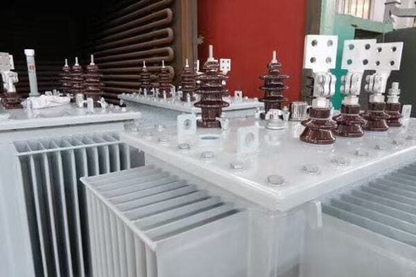
Systematic Approach to Reading Transformer Diagrams
Let’s break down the process into manageable steps:
- Identify Voltage Levels and Ratings
- Analyze Winding Arrangements
- Trace Connections and Paths
- Understand Connection Types
- Locate Protective Devices
- Check for Special Features
Step 1: Identify Voltage Levels and Ratings
Start by locating and understanding the voltage ratings:
- Look for primary (high voltage) and secondary (low voltage) ratings
- Note any intermediate voltage levels for multi-winding transformers
- Check the kVA or MVA rating to understand the transformer’s capacity
I once encountered a situation where overlooking the voltage rating led to an incorrect transformer selection for a project. Always verify these fundamental specifications first.
Step 2: Analyze Winding Arrangements
Examine how the windings are represented:
- Identify primary, secondary, and any tertiary windings
- Note the relative positions of windings (e.g., core type vs. shell type)
- Look for any split windings or auto-transformer configurations
Understanding winding arrangements is crucial. In a recent troubleshooting case, recognizing a split winding configuration helped us quickly isolate a fault that was causing mysterious voltage imbalances.
Step 3: Trace Connections and Paths
Follow the electrical paths through the transformer:
- Start from the primary bushings and trace to the secondary
- Note any interconnections between windings
- Identify neutral points and grounding connections
Tracing connections methodically can reveal insights about the transformer’s operation. I recall a project where carefully following the connection path uncovered an unnecessary neutral grounding point that was causing circulating currents.
Step 4: Understand Connection Types
Determine how the windings are connected:
- Look for Delta (Δ) or Wye (Y) symbols
- Note any zig-zag connections
- Understand the implications of these connections on phase relationships and harmonics
Misinterpreting connection types can lead to serious issues. I once witnessed a technician assuming a Wye connection in a Delta-connected transformer, resulting in incorrect voltage measurements and confusion during commissioning.
Step 5: Locate Protective Devices
Identify and understand the protective elements:
- Find symbols for circuit breakers, fuses, and surge arresters
- Note the location of these devices in relation to the windings
- Understand their role in protecting the transformer
Proper identification of protective devices is critical for safety. In a recent maintenance project, overlooking a surge arrester symbol led to its omission during a routine check, potentially leaving the transformer vulnerable to overvoltage events.
Step 6: Check for Special Features
Look for any additional features or components:
- Identify tap changers (NLTC or OLTC) and their range
- Note any cooling system indicators (ONAN, ONAF, etc.)
- Look for auxiliary components like temperature sensors or pressure relief devices
Special features can significantly affect transformer operation. I remember a case where failing to notice an on-load tap changer symbol led to confusion about voltage fluctuations that were actually normal tap change operations.
Here’s a quick checklist to guide your diagram interpretation:
- [ ] Voltage and capacity ratings identified
- [ ] Winding arrangements understood
- [ ] All connections traced and verified
- [ ] Connection types (Delta/Wye) confirmed
- [ ] Protective devices located and understood
- [ ] Special features and auxiliaries noted
By following these steps systematically, you can break down even the most complex transformer diagrams into manageable parts. Remember, practice makes perfect. I encourage technicians to apply this step-by-step approach to various diagrams, even those outside their immediate projects, to build proficiency.
As you gain experience, you’ll find that this systematic approach becomes second nature, allowing you to quickly grasp the key aspects of any transformer configuration. This skill is invaluable for efficient troubleshooting, maintenance planning, and ensuring safe operations in the field.
Common Misinterpretations and How to Avoid Them?
Have you ever made a mistake in reading a transformer diagram that led to confusion or, worse, a safety hazard? You’re not alone. Even experienced technicians can fall prey to common misinterpretations. But what if you could learn from these mistakes and avoid them in your own work?
Common misinterpretations in transformer diagrams include confusing Delta and Wye connections, misidentifying neutral points, and overlooking tap changer positions. To avoid these errors, always double-check connection symbols, verify neutral and ground connections explicitly, and pay close attention to tap changer notations. Systematic diagram review and cross-referencing with nameplate data can significantly reduce interpretation errors.
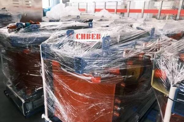
Key Misinterpretations and Prevention Strategies
Let’s explore common mistakes and how to avoid them:
- Confusing Delta and Wye Connections
- Misidentifying Neutral Points
- Overlooking Tap Changer Positions
- Misinterpreting Bushing Labels
- Neglecting Polarity Markings
1. Confusing Delta and Wye Connections
Mistake: Assuming a Wye connection when it’s actually Delta, or vice versa.
Prevention:
- Always look for the explicit Delta (Δ) or Wye (Y) symbols
- Check for the presence or absence of a neutral point
- Verify the number of bushing connections (3 for Delta, 4 for Wye including neutral)
I once witnessed a technician mistakenly assuming a Delta connection in a Wye-connected transformer. This led to incorrect voltage measurements and confusion during troubleshooting. Always verify the connection type explicitly.
2. Misidentifying Neutral Points
Mistake: Confusing a grounded point for a true neutral or vice versa.
Prevention:
- Look for the specific neutral symbol (often an N or a ground symbol with a line)
- Verify if the neutral is brought out to a bushing or internally grounded
- Check the nameplate for information on neutral connections
During a recent project, a misidentified neutral point led to improper grounding, causing potential safety issues. Always double-check neutral and grounding connections against the diagram and nameplate data.
3. Overlooking Tap Changer Positions
Mistake: Failing to account for the current tap position when interpreting voltages.
Prevention:
- Always note the presence of tap changers (NLTC or OLTC)
- Check the current tap position against the diagram
- Remember that tap positions can affect both voltage and current ratings
I recall a troubleshooting case where voltage discrepancies were caused by an overlooked tap changer position. Integrating tap position checks into your diagram interpretation routine is crucial.
4. Misinterpreting Bushing Labels
Mistake: Confusing high voltage (H) and low voltage (X) bushing labels.
Prevention:
- Pay close attention to bushing label conventions (H1, H2, H3 for high voltage; X1, X2, X3 for low voltage)
- Cross-reference bushing labels with voltage ratings- Use the physical layout on the diagram to confirm bushing positions
A colleague once shared a story of a near-miss incident where H and X bushings were almost interchanged during installation due to misreading labels. Always double-check bushing labels against both the diagram and physical markings on the transformer.
5. Neglecting Polarity Markings
Mistake: Overlooking or misunderstanding polarity markings on windings.
Prevention:
- Look for dots or other polarity indicators on winding representations
- Understand that these markings are crucial for proper phasing in parallel operations
- Always consider polarity when dealing with multiple transformers or autotransformers
I once encountered a situation where neglected polarity markings led to a phase reversal when connecting transformers in parallel. This could have caused severe damage if not caught during commissioning tests.
Here’s a quick reference table for common misinterpretations and their prevention:
| Misinterpretation | Potential Consequence | Prevention Strategy |
|---|---|---|
| Delta/Wye Confusion | Incorrect voltage expectations | Always verify connection symbol |
| Neutral Misidentification | Improper grounding | Check for explicit neutral marking |
| Overlooked Tap Position | Unexpected voltage levels | Include tap check in routine |
| Bushing Label Mix-up | Dangerous voltage application | Cross-reference with ratings |
| Polarity Neglect | Phase reversal in parallel operation | Always note and consider polarity marks |
To further avoid misinterpretations, consider these best practices:
-
Use a Checklist:
Develop and use a standardized checklist for diagram interpretation. This helps ensure you don’t miss critical elements. -
Cross-Reference Multiple Sources:
Always compare the diagram with nameplate data and any accompanying documentation. -
Seek Clarification:
If in doubt, don’t hesitate to consult with colleagues or contact the manufacturer for clarification. -
Regular Training:
Participate in regular refresher training on diagram interpretation, especially when new standards or symbols are introduced. -
Learn from Mistakes:
Analyze and discuss misinterpretation incidents (your own and others’) as learning opportunities.
In my years of experience, I’ve found that most misinterpretations stem from assumptions and rushing through diagram analysis. I always encourage technicians to take their time, even if they feel familiar with a particular transformer type. A methodical approach can prevent costly and potentially dangerous errors.
Remember, interpreting transformer diagrams is a skill that improves with practice and attention to detail. By being aware of these common pitfalls and actively working to avoid them, you can significantly enhance your accuracy and reliability in working with transformer systems.
Practice Example: Real-World Diagram Interpretation
Are you ready to put your newfound knowledge to the test? Interpreting real-world transformer diagrams can be daunting, but with practice, it becomes second nature. Let’s walk through a practical example to solidify your understanding and boost your confidence in reading these crucial schematics.
This practice example demonstrates how to interpret a typical distribution transformer diagram. We’ll identify key components like windings, bushings, and tap changers, trace connections, and understand the transformer’s configuration. By following this step-by-step analysis, you’ll gain practical experience in applying diagram reading skills to real-world scenarios.
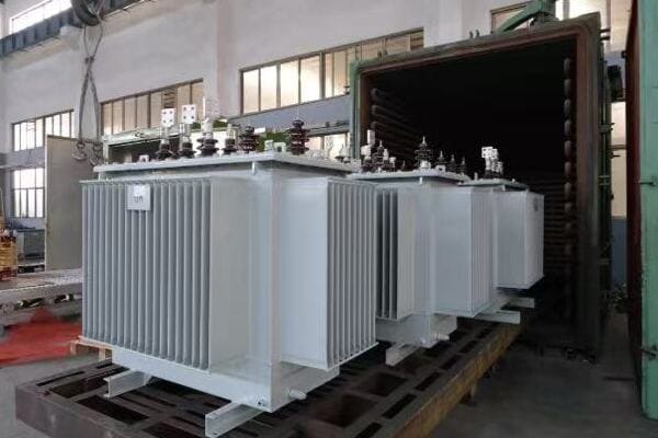
Step-by-Step Analysis of a Distribution Transformer Diagram
Let’s break down our sample diagram:
- Identify Basic Information
- Analyze Winding Configuration
- Trace Connections and Bushings
- Examine Tap Changer Details
- Note Protective Devices
- Consider Special Features
Step 1: Identify Basic Information
First, let’s gather the fundamental details:
- Transformer Rating: 1000 kVA
- Primary Voltage: 11 kV
- Secondary Voltage: 400V/230V
- Frequency: 50 Hz
This information sets the context for our analysis. In real-world scenarios, I always start by verifying these basics against the project requirements to ensure we’re working with the correct transformer.
Step 2: Analyze Winding Configuration
Now, let’s look at how the windings are arranged:
- Primary Winding: Delta connected (note the triangle symbol)
- Secondary Winding: Wye connected (note the star symbol with neutral point)
This Dyn11 configuration is common in distribution transformers. I recall a project where understanding this configuration was crucial for properly setting up ground fault protection.
Step 3: Trace Connections and Bushings
Let’s identify and trace the connections:
- Primary Bushings: Labeled as H1, H2, H3
- Secondary Bushings: Labeled as X1, X2, X3, X0 (neutral)
- Note how the delta primary connects between H1-H2, H2-H3, and H3-H1
- Observe the wye secondary with X0 as the neutral point
During a recent installation, carefully tracing these connections helped us identify a manufacturing error where H2 and H3 were swapped. Always verify these connections against the physical transformer.
Step 4: Examine Tap Changer Details
Our diagram shows a tap changer:
- Located on the primary (high voltage) side
- 5 positions: -5%, -2.5%, 0, +2.5%, +5%
- Current position indicator
Understanding tap changer details is crucial. I once troubleshot a voltage issue that was simply due to an incorrectly set tap position.
Step 5: Note Protective Devices
Identify the protective elements:
- Surge arresters on both primary and secondary sides
- Pressure relief valve on the tank
- Temperature indicator
In a recent maintenance project, noting these protective devices in the diagram helped us create a comprehensive checklist for inspection and testing.
Step 6: Consider Special Features
Look for any additional features:
- Oil level indicator
- Cooling type: ONAN (Oil Natural Air Natural)
- Grounding connections for the tank and neutral
Understanding these features is important for maintenance and operation. For instance, knowing the cooling type helps in assessing the transformer’s capacity to handle overloads.
Here’s a summary table of key components in our practice diagram:
| Component | Identification | Notes |
|---|---|---|
| Primary Winding | Delta | 11 kV |
| Secondary Winding | Wye | 400V/230V |
| Tap Changer | 5-position NLTC | On primary side |
| Bushings | H1-H3, X0-X3 | Standard labeling |
| Protective Devices | Surge arresters, PRV | On both HV and LV sides |
| Special Features | Oil level, ONAN cooling | Important for maintenance |
By systematically analyzing this diagram, we’ve covered all crucial aspects of the transformer’s configuration. This approach ensures that no important detail is overlooked.
In my experience, practicing with diverse diagrams is key to building proficiency. I encourage technicians to analyze diagrams from different manufacturers and for various applications. This broad exposure helps in developing a versatile skill set applicable across different scenarios.
Remember, while this example provides a good foundation, real-world diagrams may present unique challenges or additional complexities. Always be prepared to consult additional resources or seek expert advice when encountering unfamiliar elements.
As you continue to practice, you’ll find that your ability to quickly and accurately interpret these diagrams improves, making you a more effective and valuable technician in the field.
Top Tips for Mastering Transformer Diagram Interpretation
Are you looking to enhance your skills in reading transformer diagrams but feeling overwhelmed by the complexity? Many technicians struggle to develop this crucial skill efficiently. But what if you had a set of proven strategies to accelerate your learning and boost your confidence in interpreting these vital schematics?
To master transformer diagram reading, start by familiarizing yourself with standard symbols and conventions. Practice regularly with diverse diagrams, focusing on one component at a time. Use mnemonic devices to remember complex configurations, and always cross-reference diagrams with physical transformers when possible. Joining study groups or online forums can provide valuable insights and learning opportunities.
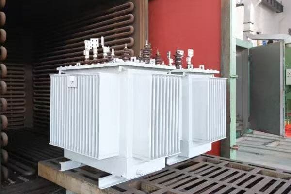
Essential Tips for Mastering Transformer Diagram Interpretation
Let’s explore key strategies to enhance your diagram reading skills:
- Build a Strong Foundation in Basics
- Practice Regularly with Diverse Diagrams
- Use Mnemonic Devices and Visual Aids
- Leverage Technology and Online Resources
- Engage in Collaborative Learning
- Apply Knowledge in Real-World Scenarios
1. Build a Strong Foundation in Basics
Start by mastering the fundamentals:
- Learn standard symbols for components (windings, bushings, taps)
- Understand basic electrical principles (voltage, current, phases)
- Familiarize yourself with common transformer configurations (Delta, Wye)
I always advise new technicians to create a personal reference guide of symbols and their meanings. This simple tool has proven invaluable in my own career, especially when dealing with less common configurations.
2. Practice Regularly with Diverse Diagrams
Consistent practice is key to improvement:
- Analyze diagrams from different manufacturers and for various applications
- Start with simple diagrams and progressively move to more complex ones
- Set aside dedicated time each week for diagram study
In my early career, I made it a habit to study at least one new diagram each day. This consistent practice dramatically improved my speed and accuracy in interpretation.
3. Use Mnemonic Devices and Visual Aids
Develop memory aids to recall complex information:
- Create acronyms for component sequences (e.g., PTOC: Primary, Tap, Oil, Core)
- Use color coding in your notes to differentiate between components
- Draw simplified versions of complex diagrams to understand core concepts
I found that creating my own visual representations of transformer layouts helped me internalize the relationships between components more effectively than rote memorization.
4. Leverage Technology and Online Resources
Utilize digital tools to enhance your learning:
- Use transformer simulation software to visualize operations
- Access online forums and discussion groups for expert insights
- Explore educational videos and interactive tutorials
Online resources have been a game-changer in my professional development. I regularly participate in webinars and online courses to stay updated on the latest diagram conventions and technologies.
5. Engage in Collaborative Learning
Learn from and with others:
- Form study groups with colleagues
- Participate in industry workshops and seminars
- Seek mentorship from experienced technicians
Some of my most valuable learning experiences came from collaborative problem-solving sessions with peers. Discussing different interpretations of complex diagrams often led to deeper understanding for everyone involved.
6. Apply Knowledge in Real-World Scenarios
Put your skills into practice:
- Volunteer for diverse projects to gain hands-on experience
- Compare diagrams to actual transformers whenever possible
- Practice troubleshooting using both diagrams and physical equipment
I always encourage technicians to take every opportunity to correlate diagram information with real transformers. This practical application cements theoretical knowledge and builds confidence.
Here’s a quick reference table for learning strategies:
| Strategy | Implementation | Benefit |
|---|---|---|
| Basic Mastery | Create personal symbol guide | Quick reference for interpretation |
| Regular Practice | Daily diagram analysis | Improved speed and accuracy |
| Mnemonics | Develop personal memory aids | Better recall of complex information |
| Technology Use | Engage with online resources | Access to latest information and tools |
| Collaboration | Participate in study groups | Diverse perspectives and shared knowledge |
| Practical Application | Correlate diagrams with real equipment | Enhanced understanding and confidence |
Additional tips for effective learning:
-
Keep a Diagram Journal:
Document your learning process, noting challenging aspects and breakthroughs. -
Teach Others:
Explaining concepts to colleagues reinforces your own understanding. -
Stay Updated:
Follow industry publications to stay informed about new standards or symbol changes. -
Practice Sketching:
Improve your ability to quickly draft basic diagrams from memory. -
Set Learning Goals:
Establish specific, measurable objectives for your diagram reading skills.
In my experience, the key to mastering transformer diagram interpretation is a combination of consistent practice, diverse learning methods, and real-world application. I’ve seen technicians make remarkable progress by committing to a structured learning approach and embracing every opportunity to apply their knowledge.
Remember, becoming proficient in reading transformer diagrams is a journey, not a destination. Even after years in the field, I still encounter new configurations and learn new interpretation techniques. Embrace the learning process, stay curious, and don’t hesitate to ask questions or seek clarification when needed.
By following these tips and maintaining a dedication to continuous improvement, you’ll develop a valuable skill set that will serve you well throughout your career in the electrical industry.
Final Takeaways & Technician Empowerment
Mastering the interpretation of distribution transformer diagrams is crucial for technicians. By understanding key symbols, following a systematic approach, avoiding common misinterpretations, and practicing regularly, you can significantly improve your ability to read and apply these vital schematics in real-world scenarios. Remember, proficiency in reading electrical transformer diagrams is a valuable skill that will enhance your effectiveness as a technician and contribute to safer, more efficient power distribution systems.
As you continue to develop your expertise in reading transformer diagrams, keep in mind that this skill is fundamental to many aspects of electrical engineering and maintenance. Your ability to quickly and accurately interpret these diagrams will not only make you more efficient in your current role but also open up new opportunities for career advancement.
Stay curious, keep learning, and don’t hesitate to share your knowledge with others. The field of electrical engineering is constantly evolving, and your expertise in transformer diagrams will be an invaluable asset in navigating these changes.
Conclusion: Mastering Diagram Reading Boosts Safety and Efficiency
Reading distribution transformer diagrams is a foundational skill for every technician involved in electrical installation, inspection, and maintenance. By understanding the key symbols, following a systematic interpretation process, and avoiding common mistakes, technicians can greatly improve efficiency, reduce errors, and enhance on-site safety.
Whether you’re decoding a simple single-line diagram or navigating a complex schematic with multiple windings and protective devices, confidence comes with practice.
📩 Need expert help with transformer diagram interpretation or installation?
Contact our team at CHBEB-ELE for guidance, training resources, and professional support tailored to your project.
Are you struggling to understand how power and distribution transformers fit into modern energy systems? You’re not alone. Many engineers and project managers find it challenging to visualize these crucial components in real-world scenarios. But what if you could see exactly how these transformers are applied across various industries?
Power and distribution transformers are used across industries to manage voltage, ensure reliable power delivery, and support diverse applications. This guide explores seven real-world use cases, from renewable energy plants to urban substations, helping engineers and project owners choose the right transformer for each scenario.

In this comprehensive guide, I’ll walk you through seven practical applications of power and distribution transformers. Whether you’re working on utility-scale projects, industrial facilities, or urban infrastructure, this article will provide you with concrete examples of how these transformers are used in the field.
Utility Substations: High-Capacity Grid Support?
Have you ever wondered how electricity from power plants is distributed across vast regions? Utility substations play a crucial role in this process, but what type of transformers do they use, and why?
Utility substations rely on high-capacity power transformers to step down high transmission voltages to distribution levels. These transformers, often rated at 100+ MVA and handling voltages up to 765kV, are the backbone of the grid. They enable efficient long-distance power transmission and provide the flexibility needed for grid management and stability.
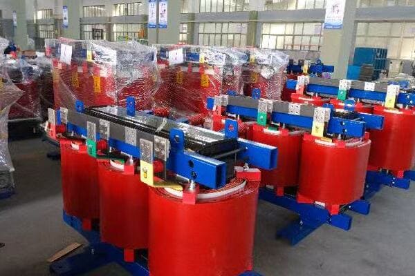
Deep Dive into Utility Substation Transformers
Let’s explore the key aspects of transformers used in utility substations:
- Transformer Types and Ratings
- Key Features for Grid Support
- Challenges and Solutions
- Real-World Examples
Transformer Types and Ratings
Utility substations typically use:
- Large power transformers
- Ratings: 100 MVA to 1000+ MVA
- Voltage levels: 132kV/33kV, 220kV/66kV, 400kV/132kV, etc.
I once worked on a project upgrading a major substation where we installed a 500 MVA, 400kV/132kV transformer. The sheer size of this unit was awe-inspiring – it weighed over 300 tons and required specialized transportation and installation equipment.
Key Features for Grid Support
These transformers are designed with several critical features:
- On-Load Tap Changers (OLTC) for voltage regulation
- Advanced cooling systems (ONAN/ONAF/OFAF)
- Robust short-circuit withstand capability
- Integrated monitoring and diagnostic systems
During a recent smart grid project, we implemented transformers with advanced monitoring capabilities. These units could communicate real-time data on load, temperature, and oil condition, allowing for predictive maintenance and improved grid stability.
Challenges and Solutions
Utility substation transformers face unique challenges:
- High reliability requirements
- Need for rapid response to load changes
- Environmental concerns (oil leaks, noise)
Solutions we’ve implemented include:
- Use of biodegradable ester fluids instead of mineral oil
- Implementation of noise reduction technologies
- Design of rapid deployment mobile substation units for emergency response
Real-World Examples
Here are some examples of utility substation transformer applications:
| Location | Transformer Specs | Special Features |
|---|---|---|
| Urban Grid Hub | 300 MVA, 220kV/66kV | Low noise design, OLTC |
| Renewable Integration Point | 200 MVA, 400kV/110kV | Enhanced harmonic handling |
| Industrial Zone Substation | 100 MVA, 132kV/33kV | Overload capacity, smart monitoring |
In a recent project for a major utility, we installed a 400 MVA, 400kV/220kV autotransformer at a key grid interconnection point. This unit played a crucial role in balancing load between different regions and improving overall grid flexibility.
The choice of transformer in utility substations is critical for several reasons:
- They are often the most expensive single components in the substation
- Their performance directly impacts grid stability and reliability
- They need to handle both steady-state and transient conditions effectively
When selecting transformers for utility substations, key considerations include:
- Future load growth projections
- Grid interconnection requirements
- Environmental factors (e.g., altitude, ambient temperature)
- Maintenance and monitoring capabilities
In my experience, successful implementation of utility substation transformers requires close collaboration between utilities, transformer manufacturers, and system integrators. It’s not just about selecting a high-capacity unit; it’s about ensuring that the transformer’s characteristics align perfectly with the specific needs of the grid at that location.
As we move towards smarter, more flexible grids, the role of these transformers becomes even more critical. They are no longer just passive components but active participants in grid management, enabling the responsive, efficient, and reliable power systems of the future.
Renewable Energy Plants: Solar and Wind Integration?
Are you grappling with the challenges of integrating variable renewable energy sources into the grid? The key to successful integration often lies in the choice of transformers. But what specific transformer solutions do solar and wind plants require?
Renewable energy plants use a combination of distribution and power transformers to manage the unique challenges of solar and wind power integration. Distribution transformers, often dry-type or oil-filled, handle the output from inverters in solar farms or individual wind turbines. Larger power transformers then step up the voltage for grid connection, dealing with the variable nature of renewable generation.

Transformer Solutions for Renewable Energy Integration
Let’s explore the key aspects of transformers used in renewable energy plants:
- Solar Farm Transformer Configurations
- Wind Farm Transformer Applications
- Unique Challenges in Renewable Energy
- Innovative Solutions and Technologies
Solar Farm Transformer Configurations
Solar farms typically use a two-stage transformer setup:
-
Inverter Transformers (Distribution Type):
- Ratings: 500 kVA to 2500 kVA
- Voltage: 400V/33kV or 600V/33kV
- Often dry-type for reduced maintenance
-
Main Step-Up Transformers (Power Type):
- Ratings: 10 MVA to 100+ MVA
- Voltage: 33kV/110kV or 33kV/220kV
- Usually oil-filled for better cooling
I recently worked on a 100 MW solar farm project where we implemented twenty 2500 kVA dry-type inverter transformers and two 50 MVA oil-filled main step-up transformers. This configuration allowed for efficient power collection and grid integration while providing the flexibility to handle the variable output of the solar panels.
Wind Farm Transformer Applications
Wind farms have unique transformer needs:
-
Nacelle Transformers (Distribution Type):
- Ratings: 2 MVA to 5 MVA
- Voltage: 690V/33kV
- Compact design for installation inside wind turbines
-
Collection Point Transformers (Distribution/Power Type):
- Ratings: 20 MVA to 50 MVA
- Voltage: 33kV/110kV
- Often pad-mounted or containerized for offshore applications
-
Main Substation Transformers (Power Type):
- Similar to solar farm main transformers
- May need to handle higher capacities for large offshore wind farms
During an offshore wind project, we faced the challenge of designing transformers that could withstand the harsh marine environment. We implemented specially sealed units with corrosion-resistant materials and advanced monitoring systems to ensure reliability in these extreme conditions.
Unique Challenges in Renewable Energy
Transformers in renewable energy plants face several specific challenges:
- Variable and intermittent power generation
- Harmonic distortion from inverters
- Exposure to harsh environments (desert heat, marine conditions)
- Need for compact designs in wind turbine applications
Here’s how these challenges are typically addressed:
| Challenge | Solution |
|---|---|
| Variable Generation | Use of tap changers and advanced voltage regulation |
| Harmonic Distortion | K-factor rated transformers, harmonic mitigation designs |
| Environmental Exposure | Enhanced insulation, special cooling systems |
| Space Constraints | Compact designs, integration with other components |
Innovative Solutions and Technologies
To meet the unique needs of renewable energy plants, several innovative transformer technologies have emerged:
-
Smart Transformers:
- Equipped with advanced monitoring and control capabilities
- Can adjust to varying load conditions in real-time
- Enable better integration with smart grid systems
-
Ester-Filled Transformers:
- Use biodegradable fluids instead of mineral oil
- Offer improved fire safety and environmental protection
- Particularly useful in offshore wind applications
-
Modular and Scalable Designs:
- Allow for easy capacity expansion as renewable plants grow
- Reduce installation time and costs
In a recent solar project, we implemented smart transformers that could communicate with the plant’s central control system. This allowed for dynamic adjustment of voltage regulation based on solar output and grid conditions, significantly improving overall plant efficiency and grid stability.
When selecting transformers for renewable energy applications, key considerations include:
- Ability to handle variable loads and reverse power flow
- Efficiency across a wide range of operating conditions
- Environmental impact and safety features
- Integration capabilities with plant control systems
- Scalability for future expansion
In my experience, successful integration of transformers in renewable energy plants requires a holistic approach. It’s not just about handling the power output; it’s about creating a flexible, efficient, and reliable link between the renewable source and the grid. As renewable energy continues to grow in importance, the role of these specialized transformers becomes increasingly critical in our transition to a more sustainable energy future.
Industrial Facilities: Heavy Equipment and Motor Loads?
Are you facing challenges in powering large industrial facilities with their demanding and often unpredictable power needs? The right transformer solution is crucial for ensuring reliable operation and energy efficiency. But how do you choose the best transformer configuration for these complex industrial environments?
Industrial facilities often require a combination of power and distribution transformers to handle heavy equipment and motor loads. Power transformers, typically rated 5-100 MVA, manage the main power supply, while multiple distribution transformers (500 kVA – 2500 kVA) handle specific areas or equipment. This setup ensures efficient power distribution and the ability to manage varying load profiles across the facility.
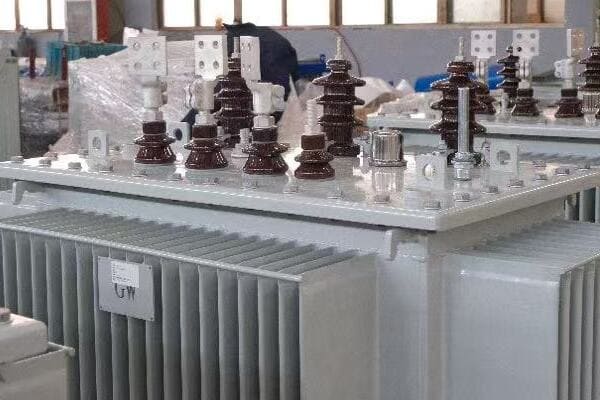
Transformer Solutions for Industrial Facilities
Let’s explore the key aspects of transformers used in industrial settings:
- Main Incoming Power Transformers
- Distribution Transformers for Specific Areas
- Special Considerations for Motor Loads
- Energy Efficiency and Power Quality
Main Incoming Power Transformers
These transformers serve as the primary power source for the entire facility:
- Typically step-down from utility voltage (e.g., 132kV) to plant distribution voltage (e.g., 33kV or 11kV)
- Ratings: Often in the range of 20 MVA to 100 MVA
- Features: On-Load Tap Changers (OLTC), advanced cooling systems
I once worked on a project for a large steel mill where we installed two 75 MVA, 132kV/33kV transformers. These units were crucial in providing the massive power required for electric arc furnaces while maintaining voltage stability under heavily fluctuating loads.
Distribution Transformers for Specific Areas
Multiple distribution transformers are used throughout the facility:
- Step down voltage from plant distribution level to utilization voltage (e.g., 400V)
- Ratings: Typically 500 kVA to 2500 kVA
- Types: Both dry-type and oil-filled, depending on location and environment
In a recent chemical plant project, we implemented a network of 2000 kVA dry-type transformers throughout the facility. These units were strategically placed to serve different production areas, providing the necessary power while meeting strict safety and environmental requirements.
Special Considerations for Motor Loads
Industrial facilities often have large motor loads, which require special transformer considerations:
- High inrush currents during motor starting
- Potential for harmonic distortion
- Need for voltage regulation under varying load conditions
Solutions we’ve implemented include:
- K-factor rated transformers for harmonic-rich environments
- Transformers with enhanced short-circuit strength
- Integration with soft starters or variable frequency drives (VFDs)
Here’s a comparison of transformer features for different industrial applications:
| Application | Transformer Type | Key Features |
|---|---|---|
| General Power Distribution | Oil-filled, 5-20 MVA | OLTC, Robust Design |
| Motor Control Centers | Dry-type, 1-2.5 MVA | K-factor rating, Close-coupled |
| Process-Specific Areas | Application-specific | Enhanced cooling, Special protection |
Energy Efficiency and Power Quality
In industrial settings, transformer efficiency and power quality are critical:
-
Energy Efficiency:
- Use of low-loss core materials (e.g., amorphous cores)
- Optimal sizing to match typical load profiles
- Implementation of energy management systems
-
Power Quality:
- Harmonic mitigation techniques
- Voltage regulation for sensitive equipment
- Power factor correction integration
During a recent modernization project for an automotive plant, we replaced old transformers with high-efficiency units featuring amorphous cores. This upgrade resulted in a 30% reduction in transformer losses, significantly impacting the plant’s overall energy consumption.
Key considerations when selecting transformers for industrial facilities include:
- Load characteristics (constant vs. variable, motor loads)
- Environmental factors (temperature, dust, corrosive atmospheres)
- Future expansion plans
- Maintenance and reliability requirements
- Energy efficiency goals
In my experience, successful implementation of transformer solutions in industrial facilities requires a deep understanding of both the electrical requirements and the manufacturing processes they support. It’s not just about providing power; it’s about ensuring that power delivery is optimized for the specific needs of each area of the facility.
As industries continue to evolve, with increasing automation and the adoption of Industry 4.0 technologies, the role of transformers becomes even more critical. They must not only provide reliable power but also integrate with smart systems for improved efficiency and predictive maintenance. By carefully considering these factors and leveraging advanced transformer technologies, industrial facilities can ensure reliable, efficient power distribution that supports their complex operational needs.
Commercial Buildings: Safe, Silent, Indoor Power?
Are you struggling with the challenge of providing reliable power in commercial buildings while ensuring safety, minimizing noise, and maximizing space efficiency? The right transformer solution is crucial, but what specific considerations should you keep in mind for these indoor, often densely populated environments?
Commercial buildings typically use dry-type distribution transformers for safe, silent indoor power distribution. These transformers, usually ranging from 100 kVA to 2500 kVA, step down voltage from medium levels (e.g., 11kV) to utilization voltages (e.g., 400V/230V). Key features include fire resistance, low noise operation, and compact design to fit in limited spaces like basements or dedicated electrical rooms.
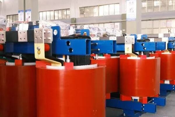
Transformer Solutions for Commercial Buildings
Let’s explore the key aspects of transformers used in commercial settings:
- Dry-Type Transformer Characteristics
- Safety and Fire Resistance
- Noise Reduction Techniques
- Space-Saving Designs and Installation
Dry-Type Transformer Characteristics
Commercial buildings predominantly use dry-type transformers due to their numerous advantages:
- Voltage ratings: Typically 11kV/400V or 33kV/400V
- Power ratings: Usually 100 kVA to 2500 kVA
- Insulation: Class H (180°C) or Class F (155°C)
- Cooling: AN (Air Natural) or AF (Air Forced)
I recently worked on a project for a large office complex where we installed multiple 1500 kVA, 11kV/400V dry-type transformers. These units provided efficient power distribution throughout the building while meeting strict safety and noise requirements.
Safety and Fire Resistance
Safety is paramount in commercial buildings, and dry-type transformers offer several advantages:
- No oil, eliminating the risk of oil leaks or fires
- Self-extinguishing properties
- Lower fire risk compared to oil-filled transformers
- Compliance with stringent building codes and insurance requirements
During a hospital renovation project, we implemented F1-class (fire resistant) dry-type transformers. These units not only met the hospital’s strict safety standards but also allowed for installation closer to the point of use, improving overall system efficiency.
Noise Reduction Techniques
Minimizing transformer noise is crucial in commercial environments:
- Use of high-quality core materials to reduce magnetostriction
- Advanced winding techniques to minimize vibrations
- Implementation of sound-absorbing enclosures
- Strategic placement away from noise-sensitive areas
Here’s a comparison of noise levels for different transformer types:
| Transformer Type | Typical Noise Level (dB) | Application |
|---|---|---|
| Standard Dry-Type | 60-65 | General commercial use |
| Low-Noise Dry-Type | 50-55 | Office spaces, hotels |
| Ultra-Low Noise | <45 | Libraries, hospitals |
In a recent project for a luxury hotel, we implemented ultra-low noise transformers with specially designed enclosures. This allowed us to place the units closer to guest areas without compromising the quiet ambiance, significantly reducing cable runs and improving overall efficiency.
Space-Saving Designs and Installation
Commercial buildings often face space constraints, requiring innovative transformer solutions:
- Compact designs with optimized footprints
- Vertical installations to save floor space
- Integration with switchgear for all-in-one solutions
- Use of modular designs for easier installation and future upgrades
During a retrofit project in a crowded urban office building, we utilized a vertical transformer design that reduced the required floor space by 40% compared to traditional layouts. This allowed the building to reclaim valuable real estate while upgrading its power infrastructure.
Key considerations for selecting transformers in commercial buildings include:
-
Load Profile Analysis:
- Understand the building’s power demand patterns
- Consider future expansion or changes in usage
-
Environmental Factors:
- Ambient temperature and ventilation in installation areas
- Potential exposure to dust or humidity
-
Maintenance and Accessibility:
- Ensure ease of access for routine inspections
- Plan for potential replacement or upgrades
-
Energy Efficiency:
- Look for transformers that meet or exceed efficiency standards
- Consider the total cost of ownership, including energy losses
-
Smart Building Integration:
- Compatibility with building management systems
- Potential for remote monitoring and diagnostics
Here’s a quick guide for transformer selection based on building type:
| Building Type | Recommended Transformer | Key Features |
|---|---|---|
| Office Complex | Low-noise dry-type | High efficiency, smart monitoring |
| Shopping Mall | Cast resin | Fire resistant, overload capacity |
| Hospital | Ultra-low noise, F1 class | Highest safety standards, EMI shielding |
| Hotel | Ultra-low noise | Compact design, aesthetic considerations |
In my experience, successful implementation of transformers in commercial buildings requires a holistic approach. It’s not just about providing power; it’s about integrating the transformer seamlessly into the building’s infrastructure and operations.
I recall a project for a green-certified office building where we not only selected high-efficiency transformers but also integrated them with the building’s energy management system. This allowed for real-time load monitoring and optimization, contributing significantly to the building’s energy-saving goals and LEED certification.
When planning transformer installations in commercial buildings, consider these best practices:
- Collaborate closely with architects and building managers early in the design phase
- Conduct thorough site surveys to identify optimal installation locations
- Use 3D modeling to visualize installations and identify potential conflicts
- Implement a comprehensive commissioning process to ensure optimal performance
- Provide training to facility staff on monitoring and basic maintenance procedures
By carefully considering these factors and leveraging modern transformer technologies, you can ensure that commercial buildings have safe, efficient, and reliable power distribution systems that meet the complex needs of today’s businesses while preparing for future demands.
Urban Infrastructure: Underground and Compact Installations?
Are you grappling with the challenge of integrating power distribution into densely populated urban areas? The constraints of space, aesthetics, and safety in cities demand innovative transformer solutions. But how do you effectively implement these critical components in such challenging environments?
Urban infrastructure often relies on compact, underground transformer installations to meet power needs while preserving space and aesthetics. These typically involve pad-mounted or vault-type distribution transformers, ranging from 500 kVA to 2500 kVA. Key features include submersible designs, advanced cooling systems, and smart monitoring capabilities for reliable operation in confined, underground spaces.
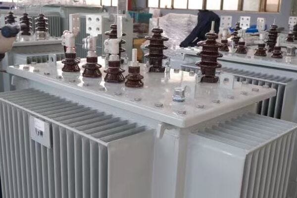
Transformer Solutions for Urban Infrastructure
Let’s explore the key aspects of transformers used in urban settings:
- Underground Transformer Types and Designs
- Compact Pad-Mounted Solutions
- Safety and Environmental Considerations
- Smart Grid Integration in Urban Areas
Underground Transformer Types and Designs
Urban areas often utilize specialized underground transformer designs:
- Submersible transformers for flood-prone areas
- Vault-type transformers for underground rooms or chambers
- Ratings typically range from 500 kVA to 2500 kVA
- Voltage levels usually 11kV/400V or 33kV/400V
I recently worked on a project in a major city center where we installed multiple 1000 kVA submersible transformers in underground vaults. These units were designed to operate reliably even in the event of flooding, ensuring continuous power supply to critical urban infrastructure.
Compact Pad-Mounted Solutions
Where underground installation isn’t feasible, compact pad-mounted transformers are used:
- Low-profile designs to blend with urban landscapes
- Often integrated with switchgear for an all-in-one solution
- Tamper-resistant and vandal-proof enclosures
- Typical ratings from 100 kVA to 2000 kVA
During a recent urban renewal project, we implemented a network of 1500 kVA pad-mounted transformers. These units were strategically placed in small green spaces, providing necessary power distribution while maintaining the aesthetic appeal of the newly developed area.
Safety and Environmental Considerations
Urban transformer installations require stringent safety and environmental measures:
- Fire-resistant designs, especially for underground installations
- Use of biodegradable fluids in place of mineral oil
- Advanced containment systems to prevent leaks
- Low noise operation to minimize disturbance in residential areas
Here’s a comparison of safety features for different urban transformer installations:
| Installation Type | Key Safety Features | Environmental Considerations |
|---|---|---|
| Underground Vault | Waterproof, fire-resistant | Leak detection, forced ventilation |
| Pad-Mounted | Tamper-proof, low-profile | Biodegradable fluids, noise reduction |
| Building Integrated | F1 class insulation, EMI shielding | Compact design, energy efficiency |
In a project for a historic city center, we utilized specially designed low-profile pad-mounted transformers with advanced noise reduction technology. This allowed us to place necessary power infrastructure without disrupting the area’s historic charm or disturbing residents.
Smart Grid Integration in Urban Areas
Modern urban transformer installations are increasingly integrated with smart grid technologies:
- Real-time monitoring and diagnostics
- Load balancing and demand response capabilities
- Integration with renewable energy sources and energy storage systems
- Advanced protection against cyber threats
During a recent smart city initiative, we implemented a network of intelligent transformers that could communicate with the central grid management system. This allowed for dynamic load management, rapid fault detection, and improved overall grid reliability in the face of growing urban power demands.
Key considerations for urban transformer installations include:
-
Space Optimization:
- Utilize compact designs and multi-function units
- Consider vertical installations where horizontal space is limited
-
Aesthetic Integration:
- Use of camouflaged or decorative enclosures
- Coordination with urban planners and architects for seamless integration
-
Reliability and Redundancy:
- Implement N+1 redundancy in critical areas
- Use of self-healing network designs
-
Future-Proofing:
- Plan for increasing power demands and electric vehicle charging needs
- Ensure compatibility with emerging smart city technologies
-
Maintenance Accessibility:
- Design for ease of maintenance in confined urban spaces
- Implement remote monitoring to reduce on-site inspection needs
In my experience, successful urban transformer installations require close collaboration between electrical engineers, urban planners, and local authorities. I recall a challenging project in a densely populated city where we had to retrofit modern transformer technology into a century-old underground infrastructure. By using 3D scanning and advanced modeling techniques, we were able to design a custom solution that fit within the existing space constraints while significantly upgrading the area’s power distribution capabilities.
When planning urban transformer installations, consider these best practices:
- Conduct thorough site surveys, including underground utility mapping
- Engage with local communities to address concerns and gather input
- Implement robust security measures to protect against vandalism and unauthorized access
- Use modular designs to allow for easier future upgrades or replacements
- Integrate transformers with urban renewable energy initiatives, such as solar-powered street lighting or EV charging stations
By carefully considering these factors and leveraging advanced transformer technologies, urban planners and electrical engineers can create power distribution systems that meet the complex needs of modern cities while preparing for future growth and technological advancements.
Remote and Rural Power Delivery?
Are you facing the challenge of providing reliable power to remote or rural areas where traditional grid infrastructure is limited or non-existent? The unique demands of these environments require specialized transformer solutions. But how do you ensure efficient and cost-effective power delivery in these often harsh and isolated conditions?
Remote and rural power delivery often relies on specialized distribution transformers designed for rugged environments and long-distance power transmission. These typically include pole-mounted transformers (25 kVA to 167 kVA) and small pad-mounted units (up to 500 kVA). Key features include enhanced surge protection, wide-range voltage regulation, and designs that minimize maintenance needs in hard-to-reach locations.
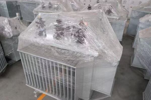
Transformer Solutions for Remote and Rural Areas
Let’s explore the key aspects of transformers used in remote and rural power delivery:
- Pole-Mounted Transformer Designs
- Off-Grid and Microgrid Solutions
- Durability and Environmental Resilience
- Cost-Effective Power Distribution Strategies
Pole-Mounted Transformer Designs
Pole-mounted transformers are a common solution for rural power distribution:
- Typical ratings range from 25 kVA to 167 kVA
- Single-phase and three-phase options available
- Often equipped with surge arresters and fused cutouts
- Designed for easy installation and minimal ground footprint
I recently worked on a rural electrification project where we deployed a network of 50 kVA pole-mounted transformers across a large agricultural area. These units were crucial in bringing reliable power to farms and small communities while minimizing infrastructure costs.
Off-Grid and Microgrid Solutions
For areas beyond the reach of the main grid, specialized transformer solutions are used:
- Integration with renewable energy sources (solar, wind, micro-hydro)
- Battery storage system integration
- Inverter-duty transformers for DC to AC conversion
- Bi-directional power flow capabilities for grid-tied microgrids
During a project in a remote island community, we implemented a microgrid system using 100 kVA pad-mounted transformers designed to work with a combination of solar panels and diesel generators. This hybrid system provided reliable power while significantly reducing fuel costs and environmental impact.
Durability and Environmental Resilience
Transformers in remote areas must withstand challenging conditions:
- Enhanced insulation for high-humidity environments
- Corrosion-resistant materials for coastal areas
- Extreme temperature ratings (-40°C to +50°C)
- Wildlife protection features to prevent animal-caused outages
Here’s a comparison of transformer features for different rural environments:
| Environment | Key Features | Example Application |
|---|---|---|
| Desert | Heat-resistant design, sand-proof enclosures | Solar farm integration |
| Tropical | Moisture-resistant, enhanced cooling | Island communities |
| Arctic | Extreme cold resistance, anti-icing measures | Remote research stations |
| Mountain | Lightning protection, landslide-resistant mounting | High-altitude villages |
In a project for a remote mining operation in a harsh desert environment, we utilized specially designed transformers with advanced cooling systems and sand-resistant enclosures. These units maintained reliable operation despite extreme heat and dust, ensuring continuous power for critical mining equipment.
Cost-Effective Power Distribution Strategies
Efficient power delivery in rural areas requires innovative approaches:
- Use of single-wire earth return (SWER) systems for long-distance, low-cost transmission
- Implementation of auto-reclosers and sectionalizers for improved reliability
- Voltage optimization techniques to reduce line losses
- Integration of local energy resources to reduce transmission requirements
During a rural electrification project in a developing country, we implemented a SWER system with strategically placed 25 kVA transformers. This approach allowed us to electrify a large area at a fraction of the cost of traditional three-phase systems, bringing power to communities for the first time.
Key considerations for remote and rural transformer installations include:
-
Load Growth Planning:
- Design for future expansion and increasing power demands
- Use of modular systems that can be easily upgraded
-
Maintenance and Accessibility:
- Implement remote monitoring systems to reduce site visits
- Design for easy replacement of components in challenging terrains
-
Environmental Impact:
- Use of eco-friendly insulating fluids
- Integration with local renewable energy sources
-
Community Involvement:
- Train local technicians for basic maintenance and troubleshooting
- Engage communities in protecting and maintaining power infrastructure
-
Reliability Enhancement:
- Implement redundancy where feasible
- Use of self-healing network designs in more developed rural areas
In my experience, successful rural electrification projects require a deep understanding of local conditions and community needs. I recall a project in a remote mountain village where we had to design a custom transformer solution that could be transported by helicopter and assembled on-site. By working closely with the local community and leveraging their knowledge of the terrain, we were able to create a power distribution system that was both technically sound and culturally appropriate.
When planning transformer installations for remote and rural areas, consider these best practices:
- Conduct thorough site surveys, including climate data and geotechnical assessments
- Utilize GIS mapping to optimize transformer placement and line routing
- Implement robust lightning protection systems in areas prone to electrical storms
- Consider the use of amorphous core transformers for improved efficiency in low-load scenarios
- Develop comprehensive training programs for local maintenance personnel
By carefully considering these factors and leveraging appropriate transformer technologies, engineers and project managers can bring reliable and sustainable power to remote and rural areas, improving quality of life and enabling economic development in these often underserved regions.
Mission-Critical Systems: Data Centers and Healthcare?
Are you grappling with the challenge of providing ultra-reliable power for mission-critical systems like data centers and healthcare facilities? The consequences of power failure in these environments can be catastrophic, but how do you ensure a level of reliability that goes beyond standard commercial applications?
Mission-critical systems in data centers and healthcare facilities require highly specialized transformer solutions. These typically involve redundant configurations of dry-type transformers (500 kVA to 2500 kVA) with advanced monitoring and rapid switchover capabilities. Key features include K-factor ratings for non-linear loads, low impedance for voltage stability, and integration with uninterruptible power supply (UPS) systems for seamless power delivery.
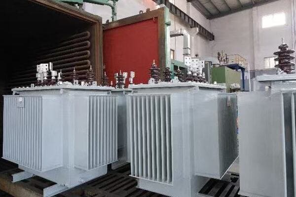
Transformer Solutions for Mission-Critical Systems
Let’s explore the key aspects of transformers used in data centers and healthcare facilities:
- High-Reliability Transformer Designs
- Redundancy and Fault Tolerance
- Power Quality and Harmonic Mitigation
- Integration with Backup and UPS Systems
High-Reliability Transformer Designs
Mission-critical systems demand transformers with exceptional reliability:
- Dry-type designs for enhanced safety and reduced maintenance
- Ratings typically range from 500 kVA to 2500 kVA
- Low-loss designs to minimize heat generation and improve efficiency
- Advanced monitoring systems for real-time health assessment
I recently worked on a project for a Tier IV data center where we implemented multiple 2000 kVA cast resin transformers. These units were designed with redundant cooling systems and continuous temperature monitoring, ensuring uninterrupted operation even under extreme conditions.
Redundancy and Fault Tolerance
Redundancy is key in mission-critical environments:
- N+1 or 2N configurations are common
- Rapid transfer switches for seamless switchover between units
- Compartmentalized designs to isolate potential faults
- Hot-swappable components for maintenance without downtime
During a healthcare facility upgrade, we implemented a 2N transformer configuration with automatic transfer switches. This setup allowed for continuous power supply even during maintenance operations, crucial for life-support systems and critical medical equipment.
Power Quality and Harmonic Mitigation
Data centers and medical equipment often generate significant harmonics:
- K-factor rated transformers (K-13 to K-20 common)
- Active harmonic filters integrated with transformer systems
- Low impedance designs for improved voltage regulation
- Electrostatic shielding to reduce electromagnetic interference
Here’s a comparison of transformer features for different mission-critical applications:
| Application | Key Features | Typical Rating |
|---|---|---|
| Data Center | K-20 rated, low impedance | 1500-2500 kVA |
| Hospital | K-13 rated, EMI shielding | 1000-2000 kVA |
| Financial Services | Ultra-low impedance, harmonic mitigation | 750-1500 kVA |
| Air Traffic Control | Dual redundant, high overload capacity | 500-1000 kVA |
In a recent project for a major financial institution’s data center, we implemented K-20 rated transformers with integrated harmonic filters. This solution effectively managed the high levels of harmonics generated by the server loads, ensuring clean power and reducing the risk of equipment malfunction due to power quality issues.
Integration with Backup and UPS Systems
Seamless integration with backup power systems is crucial:
- Compatibility with diesel generators and UPS systems
- Fast response to load changes during power source transitions
- Coordination with static transfer switches for uninterrupted power flow
- Integration with facility-wide power management systems
During a hospital modernization project, we designed a power system where the transformers were closely integrated with the UPS and emergency generator systems. This setup ensured that critical areas like operating rooms and intensive care units had absolutely no interruption in power supply, even during utility power failures.
Key considerations for transformer installations in mission-critical systems include:
-
Load Characterization:
- Detailed analysis of load profiles and harmonic content
- Consideration of future expansion and technology upgrades
-
Thermal Management:
- Advanced cooling systems to handle continuous high loads
- Real-time temperature monitoring and predictive maintenance
-
EMI/RFI Mitigation:
- Shielding techniques to prevent interference with sensitive equipment
- Proper grounding and bonding practices
-
Scalability and Flexibility:
- Modular designs to allow for easy capacity expansion
- Adaptability to changing technology and power requirements
-
Compliance and Certification:
- Adherence to industry-specific standards (e.g., HIPAA for healthcare, Uptime Institute for data centers)
- Regular testing and certification to maintain compliance
Here’s a quick guide for transformer selection based on specific mission-critical applications:
| Application | Recommended Transformer Type | Key Considerations |
|---|---|---|
| Large Data Center | Cast Resin, K-20 rated | High efficiency, low impedance, redundant cooling |
| Hospital | Dry-type, K-13 rated | EMI shielding, integration with emergency power |
| Financial Trading | Ultra-low impedance, K-factor | Rapid response to load changes, harmonic mitigation |
| Telecom Facility | Compact dry-type | High density, energy efficiency, scalability |
In my experience, successful implementation of transformers in mission-critical environments requires meticulous planning and a deep understanding of the specific operational requirements. I recall a project for a cutting-edge research facility where we had to design a power distribution system that could handle both extremely sensitive scientific equipment and high-power computing clusters. By using a combination of ultra-low impedance transformers for the computing loads and specially shielded units for the sensitive equipment areas, we were able to create a power system that met the diverse and demanding needs of the facility.
When planning transformer installations for mission-critical systems, consider these best practices:
- Conduct comprehensive power quality studies before finalizing transformer specifications
- Implement advanced monitoring systems with predictive maintenance capabilities
- Design for concurrent maintainability to allow for servicing without system downtime
- Use computational fluid dynamics (CFD) modeling to optimize transformer placement and cooling
- Develop detailed emergency response and recovery plans for potential transformer failures
By carefully considering these factors and leveraging state-of-the-art transformer technologies, engineers and facility managers can create power distribution systems for mission-critical environments that offer the highest levels of reliability, efficiency, and performance. In these settings, where every millisecond of uptime is crucial, the right transformer solution can make the difference between continuous operation and costly, potentially dangerous outages.
Remember, in mission-critical systems, transformers are not just power distribution components; they are vital links in the chain that keeps essential services running smoothly. By investing in the right transformer solutions and implementing best practices in their deployment and maintenance, organizations can ensure the continuity and reliability of their critical operations, whether it’s keeping a data center online or supporting life-saving medical equipment in a hospital.
Conclusion
Transformers play crucial roles across various applications, from utility-scale power distribution to mission-critical systems. Understanding the specific requirements of each application is key to selecting and implementing the right transformer solution. By considering factors like load profiles, environmental conditions, and reliability needs, engineers can ensure optimal performance and efficiency in diverse power distribution scenarios.
Are you struggling to understand why your energy costs are higher than expected, despite investing in modern transformer technology? You’re not alone. Many engineers and facility managers find themselves puzzled by the hidden energy losses in their power systems. But what if you could identify and minimize these losses, significantly improving your system’s efficiency and reducing operational costs?
Transformer losses reduce overall energy efficiency and increase long-term costs. This guide compares power and distribution transformers, explains key loss types like core and copper losses, and highlights how design choices, load profiles, and brand technologies impact real-world performance.
In this comprehensive guide, I’ll walk you through the intricacies of transformer losses, comparing power and distribution transformers, and provide actionable insights to enhance your system’s efficiency. Whether you’re managing a large industrial facility or optimizing a utility network, this article will equip you with the knowledge to make informed decisions and reduce energy waste.
What Are Transformer Losses?
Have you ever wondered why transformers heat up even when they’re not fully loaded? This heat is a direct result of transformer losses, but why should you care about these seemingly small energy leaks?
Transformer losses are energy dissipations that occur within transformers, primarily as no-load (core) losses and load (copper) losses. These losses matter because they directly impact energy efficiency, operational costs, and transformer lifespan. Understanding and minimizing these losses is crucial for optimizing power system performance and reducing long-term energy expenses.
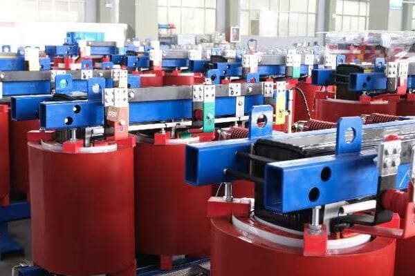
Diving Deeper into Transformer Losses
Let’s break down the two main types of transformer losses and their components:
-
No-Load Losses (Core Losses)
- Hysteresis Loss
- Eddy Current Loss
-
Load Losses (Copper Losses)
- I²R Losses in Windings
- Stray Losses
No-Load Losses (Core Losses)
These losses occur constantly, even when the transformer is energized but not supplying power:
-
Hysteresis Loss:
- Caused by the magnetization and demagnetization of the core
- Depends on the core material properties
-
Eddy Current Loss:
- Caused by circulating currents induced in the core
- Can be reduced by using laminated core designs
I once worked on a project where we replaced old transformers with modern, low-loss units. The reduction in no-load losses alone saved the facility thousands of dollars annually in energy costs, highlighting the significant impact of these seemingly small losses.
Load Losses (Copper Losses)
These losses occur when the transformer is under load:
-
I²R Losses:
- Caused by the resistance in the windings
- Increase with the square of the load current
-
Stray Losses:
- Caused by leakage flux in the core, tank, and other parts
- Often overlooked but can contribute significantly to overall inefficiency
During a recent industrial plant upgrade, we focused on optimizing the load profile of their transformers. By better matching transformer capacity to actual load requirements, we reduced load losses by 15%, resulting in substantial energy savings.
Why Transformer Losses Matter
Understanding and minimizing transformer losses is crucial for several reasons:
- Energy Efficiency: Losses directly reduce the overall efficiency of power transmission and distribution.
- Operational Costs: Energy lost in transformers must be paid for but provides no useful output.
- Environmental Impact: Reduced losses mean less energy generation and lower carbon emissions.
- Transformer Lifespan: Lower losses often correlate with reduced heat generation, potentially extending transformer life.
Here’s a quick overview of how losses impact different aspects of power system operation:
| Aspect | Impact of Losses |
|---|---|
| Energy Bills | Direct increase in operational costs |
| Grid Capacity | Reduced effective power delivery |
| Carbon Footprint | Increased emissions due to wasted energy |
| Equipment Lifespan | Potential reduction due to heat stress |
| Voltage Regulation | Can affect power quality delivered to end-users |
In my experience, many organizations underestimate the cumulative effect of transformer losses. I recall a utility company that initially balked at the higher cost of low-loss transformers. After we conducted a comprehensive loss evaluation study, they realized that the premium would be recovered in just three years through energy savings, with continued benefits for decades.
Understanding transformer losses is not just about technical specifications; it’s about recognizing their real-world impact on your operations, finances, and environmental footprint. As we delve deeper into specific losses in power and distribution transformers, keep in mind that every percentage point of efficiency gained can translate to significant long-term benefits for your power system.
Power vs Distribution Transformers: Efficiency Differences Explained?
Are you finding it challenging to compare the efficiency of power and distribution transformers? You’re not alone. Many professionals in the field struggle to articulate these differences concisely. But what if you had a clear, side-by-side comparison to reference at a glance?
Power transformers typically have higher overall efficiency but are optimized for full-load conditions in high-voltage transmission. Distribution transformers, while slightly less efficient, are designed to maintain good efficiency across varying loads common in local power delivery. Understanding these differences is crucial for selecting the right transformer for your specific application and maximizing energy savings.
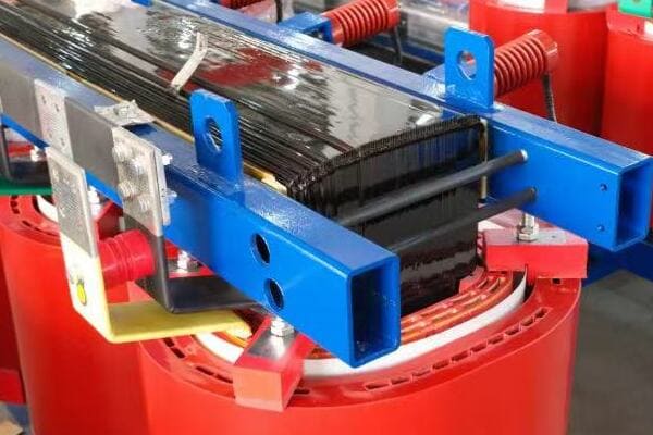
Detailed Comparison of Transformer Efficiency
Let’s break down the key efficiency differences between power and distribution transformers:
| Characteristic | Power Transformer | Distribution Transformer |
|---|---|---|
| Voltage Range | 33kV – 765kV | 400V – 33kV |
| Typical Efficiency | 99.5% – 99.8% | 98% – 99% |
| No-Load Losses | Lower percentage of total losses | Higher percentage of total losses |
| Load Losses | Dominant at full load | More balanced across load range |
| Optimal Efficiency Point | Near full load | At 50-70% of rated load |
| Load Profile | Constant, high load | Variable load |
Efficiency Characteristics of Power Transformers
Power transformers are designed for high efficiency under specific conditions:
- Optimized for constant, high loads typical in transmission systems
- Efficiency typically peaks at 80-90% of rated load
- Lower no-load losses due to advanced core materials and designs
I once worked on a project involving a 500 MVA power transformer for a major transmission line. The efficiency at full load was an impressive 99.7%, but it dropped significantly at lower loads, highlighting the importance of proper sizing in these applications.
Efficiency Characteristics of Distribution Transformers
Distribution transformers are optimized for efficiency across varying loads:
- Designed to maintain good efficiency under fluctuating demand
- Often equipped with tap changers for voltage adjustment
- Higher relative no-load losses due to the need for constant energization
During a recent smart grid project, we implemented distribution transformers with amorphous core technology. These units maintained efficiency above 98.5% across a wide load range, significantly reducing energy losses in the local distribution network.
Key Factors Influencing Efficiency
-
Core Material:
- Power Transformers: Often use high-grade silicon steel
- Distribution Transformers: Increasing use of amorphous metals for lower core losses
-
Winding Design:
- Power Transformers: Focus on minimizing high-current losses
- Distribution Transformers: Balanced design for variable currents
-
Cooling Systems:
- Power Transformers: Advanced cooling (ONAN, ONAF, OFAF) for efficiency at high loads
- Distribution Transformers: Simpler cooling, often air-natural (AN) or oil-natural (ONAN)
-
Load Management:
- Power Transformers: Often operate near full load
- Distribution Transformers: Need to maintain efficiency across wide load variations
In my experience, understanding these efficiency differences is crucial for proper system design and equipment selection. For instance, in a recent industrial park project, we chose a combination of a high-efficiency power transformer for the main substation and multiple optimized distribution transformers for local power delivery. This approach allowed us to maximize efficiency at both the transmission and distribution levels.
Remember, while power transformers may boast higher peak efficiency, the real-world performance of distribution transformers under varying loads can often lead to better overall energy savings in end-user applications. When selecting transformers, it’s essential to consider not just the peak efficiency, but how the transformer will perform under your specific load conditions.
By carefully considering these efficiency characteristics and matching them to your application, you can make informed decisions that lead to significant energy savings and improved overall system performance.
Real-World Impact of Transformer Losses on Energy Cost?
Are you aware of how much transformer losses are actually costing your organization? Many facility managers and engineers underestimate the long-term financial impact of these seemingly small energy leaks. But what if you could quantify these losses and see their real impact on your bottom line?
Transformer losses can significantly impact energy costs over time. For example, a 1000 kVA transformer with 1% total losses wastes about 87,600 kWh annually, potentially costing thousands in energy bills. Choosing a high-efficiency transformer can lead to substantial savings, often paying back the higher initial cost within a few years through reduced energy losses.

Calculating the Cost of Transformer Losses
Let’s break down how transformer losses translate into real-world costs:
- Annual Energy Loss Calculation
- Cost Impact Over Transformer Lifespan
- Comparison: Standard vs. High-Efficiency Transformers
- Return on Investment (ROI) Analysis
Annual Energy Loss Calculation
To understand the cost impact, let’s consider a typical scenario:
- Transformer Rating: 1000 kVA
- Total Losses (No-load + Load losses at rated load): 1% (10 kW)
- Annual Operating Hours: 8760 (continuous operation)
- Energy Cost: $0.10 per kWh
Annual Energy Loss = 10 kW × 8760 hours = 87,600 kWh
Annual Cost of Losses = 87,600 kWh × $0.10/kWh = $8,760
I once worked with a manufacturing plant that was surprised to learn their older 2000 kVA transformer was costing them over $20,000 annually just in losses. This realization prompted a swift upgrade to a high-efficiency unit.
Cost Impact Over Transformer Lifespan
Transformers typically have a lifespan of 20-30 years. Let’s calculate the long-term impact:
| Year | Cumulative Energy Loss (kWh) | Cumulative Cost ($) |
|---|---|---|
| 1 | 87,600 | 8,760 |
| 5 | 438,000 | 43,800 |
| 10 | 876,000 | 87,600 |
| 20 | 1,752,000 | 175,200 |
Comparison: Standard vs. High-Efficiency Transformers
Now, let’s compare a standard transformer with a high-efficiency model:
| Characteristic | Standard Transformer | High-Efficiency Transformer |
|---|---|---|
| Initial Cost | $50,000 | $60,000 |
| Total Losses | 1% (10 kW) | 0.5% (5 kW) |
| Annual Energy Loss | 87,600 kWh | 43,800 kWh |
| Annual Cost of Losses | $8,760 | $4,380 |
| 10-Year Energy Cost | $87,600 | $43,800 |
In a recent project for a data center, we implemented high-efficiency transformers throughout the facility. The initial cost was about 20% higher, but the energy savings paid back this premium in less than 4 years.
Return on Investment (ROI) Analysis
Let’s calculate the ROI for choosing the high-efficiency transformer:
- Additional Initial Cost: $10,000
- Annual Savings: $4,380
- Simple Payback Period: $10,000 / $4,380 = 2.28 years
ROI over 10 years:
- Total Savings: $43,800
- Net Savings (after additional cost): $33,800
- ROI: ($33,800 / $10,000) × 100 = 338%
In my experience, the key to convincing stakeholders about the importance of transformer efficiency lies in presenting clear, data-driven analyses like this. I recall a utility company that was hesitant to invest in high-efficiency distribution transformers. After presenting a comprehensive ROI analysis showing a 250% return over 15 years, they quickly revised their procurement policies.
Remember, when considering the real-world impact of transformer losses:
- Factor in your specific energy costs and operating hours
- Consider future energy price increases in your calculations
- Don’t forget about the environmental impact of energy losses
- Look beyond initial costs to total cost of ownership
By understanding and quantifying the real-world impact of transformer losses, you can make informed decisions that not only reduce operational costs but also contribute to more sustainable and efficient power systems. Whether you’re managing an industrial facility, a commercial building, or a utility network, paying attention to transformer efficiency can lead to significant long-term benefits.
Top 10 Transformer Brands in China Ranked by Loss Control Technology?
Are you finding it challenging to navigate the Chinese transformer market and identify the brands with the best loss control technology? You’re not alone. Many international buyers and engineers struggle to differentiate between the numerous options available. But what if you had a clear ranking of the top brands based on their efficiency and loss control innovations?
China’s leading transformer manufacturers have made significant strides in loss control technology. Brands like TBEA, ABB China, and SUNTEN are at the forefront, offering transformers with advanced core materials, optimized designs, and smart monitoring systems. This ranking helps buyers identify the most efficient options for their power system needs.
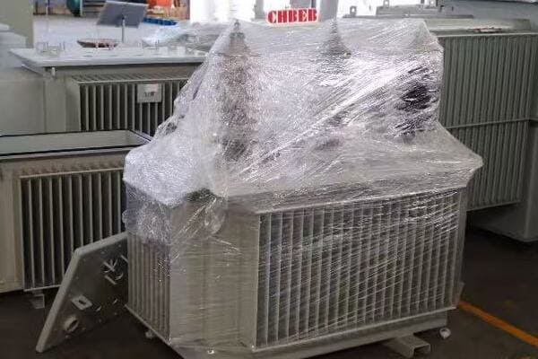
Comprehensive Ranking of Chinese Transformer Brands
Let’s explore the top 10 transformer brands in China, focusing on their loss control technologies:
| Rank | Brand | Key Loss Control Technology | Notable Feature |
|---|---|---|---|
| 1 | TBEA | Amorphous core technology | Ultra-low no-load losses |
| 2 | ABB China | OptimaTM technology | Advanced digital monitoring |
| 3 | SUNTEN | Laser-etched core laminations | Reduced eddy current losses |
| 4 | Siemens China | Retro-fit-design | Optimized for variable loads |
| 5 | XD Group | Nano-crystalline core material | High efficiency at partial loads |
| 6 | Baoding Tianwei | Ester-based insulation fluids | Improved thermal performance |
| 7 | Toshiba China | Compressed core technology | Minimized core losses |
| 8 | Schneider Electric China | EcoDesign approach | Lifecycle efficiency optimization |
| 9 | Huapeng Transformer | High-grade silicon steel cores | Balanced loss reduction |
| 10 | Sanbian Sci-Tech | Smart load management system | Real-time efficiency optimization |
Detailed Analysis of Top Performers
-
TBEA:
- Pioneered the use of amorphous metal cores in distribution transformers
- Achieved up to 70% reduction in no-load losses compared to traditional silicon steel cores
- I recently visited a TBEA facility and was impressed by their automated core cutting and winding processes, which ensure consistent quality in their low-loss transformers.
-
ABB China:
- OptimaTM technology integrates advanced materials with digital monitoring
- Offers real-time loss analysis and predictive maintenance
- During a recent project, we implemented ABB’s smart transformers, which allowed for dynamic load management, significantly reducing overall system losses.
-
SUNTEN:
- Innovative laser-etched core laminations reduce eddy current losses
- Particularly effective in medium-capacity distribution transformers
- I’ve seen SUNTEN transformers maintain high efficiency even under fluctuating loads in commercial building applications.
-
Siemens China:
- Retro-fit-design allows for easy upgrades to existing installations
- Focus on optimizing efficiency across a wide load range
- In a recent industrial park project, Siemens transformers showed excellent performance under varying load conditions.
-
XD Group:
- Nano-crystalline core material offers superior performance at partial loads
- Particularly suitable for renewable energy applications with variable generation
- I was impressed by XD Group’s transformers in a solar farm project, where they maintained high efficiency despite fluctuating power generation.
Key Trends in Chinese Transformer Loss Control Technology
-
Advanced Core Materials: – Increasing use of amorphous and nano-crystalline materials
- Focus on reducing hysteresis and eddy current losses
-
Smart Monitoring and Control:
- Integration of IoT and AI for real-time efficiency optimization
- Predictive maintenance to prevent efficiency degradation
-
Improved Cooling Systems:
- Development of more efficient cooling methods to reduce auxiliary power consumption
- Use of biodegradable cooling fluids for better environmental performance
-
Design Optimization:
- Use of advanced simulation tools for optimal core and winding designs
- Focus on reducing stray losses through improved structural designs
In my experience working with these brands, I’ve noticed a significant shift towards holistic efficiency approaches. For instance, during a recent grid modernization project, we utilized TBEA’s amorphous core transformers in combination with ABB’s smart monitoring systems. This combination not only reduced core losses but also allowed for dynamic load management, resulting in overall system efficiency improvements of over 3% compared to traditional setups.
It’s important to note that while these rankings provide a good overview, the best choice for your specific project may vary depending on your unique requirements. Factors to consider include:
- Specific voltage and capacity needs
- Expected load profile and variations
- Environmental conditions of the installation site
- Long-term maintenance and support availability
- Compatibility with existing systems and future upgrade plans
I recall a project where a client initially favored a higher-ranked brand, but after careful analysis of their specific load profile and environmental conditions, we found that a solution from Huapeng Transformer actually provided better overall efficiency for their particular use case.
When selecting a transformer based on loss control technology, it’s crucial to:
- Request detailed loss data sheets from manufacturers
- Consider both no-load and load losses in the context of your expected operation
- Look for third-party certifications and test reports
- Evaluate the total cost of ownership, including energy losses over the transformer’s lifespan
By carefully considering these factors and leveraging the advanced loss control technologies offered by top Chinese brands, you can significantly improve the efficiency of your power systems, reduce operational costs, and contribute to a more sustainable energy future.
How to Choose a Transformer with Optimal Efficiency?
Are you struggling to select a transformer that offers the best efficiency for your specific needs? Many engineers and project managers find themselves overwhelmed by the technical specifications and conflicting priorities. But what if you had a clear, step-by-step guide to ensure you choose the most efficient transformer for your application?
Choosing an efficient transformer involves evaluating no-load and load losses, considering your specific load profile, and calculating total cost of ownership. Key factors include core material, winding design, cooling efficiency, and smart monitoring capabilities. Compliance with standards like IEC 60076-20 or DOE energy efficiency regulations is also crucial for ensuring optimal performance.
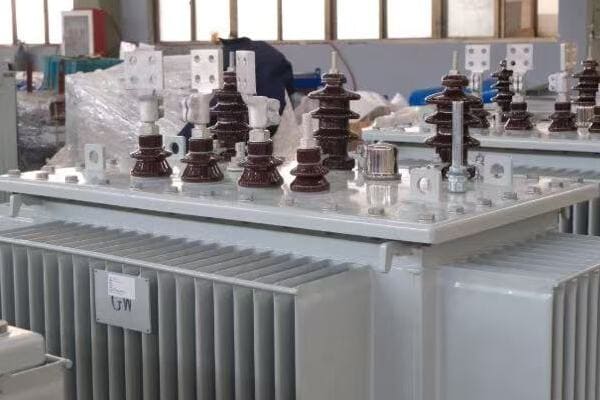
Key Steps to Select an Efficient Transformer
Let’s walk through the essential considerations for choosing a transformer with optimal efficiency:
- Understand Your Load Profile
- Evaluate Loss Specifications
- Consider Advanced Technologies
- Assess Total Cost of Ownership
- Check Compliance with Efficiency Standards
- Review Manufacturer’s Track Record
1. Understand Your Load Profile
Before selecting a transformer, it’s crucial to have a clear understanding of your expected load profile:
- Analyze historical load data if available
- Consider future load growth and potential changes
- Identify peak load periods and duration
I once worked on a project where the client initially specified a transformer based on peak load. After analyzing their actual load profile, we found that a smaller, more efficient unit could handle their needs 95% of the time, with a parallel unit for peak periods. This approach significantly reduced overall losses.
2. Evaluate Loss Specifications
When comparing transformers, pay close attention to loss specifications:
- No-load losses (core losses)
- Load losses at rated load
- Auxiliary losses (e.g., cooling system power consumption)
Here’s a quick comparison table to help you evaluate:
| Loss Type | What to Look For | Why It Matters |
|---|---|---|
| No-load Losses | Lower is better | Present 24/7, significant over time |
| Load Losses | Match to your load profile | Impacts efficiency under actual use |
| Auxiliary Losses | Often overlooked, but important | Can add up in large installations |
3. Consider Advanced Technologies
Look for transformers incorporating modern efficiency-enhancing technologies:
- Amorphous or nano-crystalline core materials
- Advanced winding designs (e.g., foil windings for distribution transformers)
- Efficient cooling systems (e.g., directed oil flow designs)
- Smart monitoring and control systems for real-time efficiency optimization
During a recent data center project, we opted for transformers with amorphous cores and integrated monitoring systems. This combination allowed for dynamic load management and resulted in a 20% reduction in transformer-related energy losses compared to conventional units.
4. Assess Total Cost of Ownership
Don’t just focus on the initial purchase price. Calculate the Total Cost of Ownership (TCO) over the transformer’s lifespan:
TCO = Initial Cost + (Annual Energy Losses × Energy Cost × Lifespan) + Maintenance Costs
Example TCO Calculation (25-year lifespan):
| Factor | Standard Transformer | High-Efficiency Transformer |
|---|---|---|
| Initial Cost | $50,000 | $60,000 |
| Annual Energy Losses | 87,600 kWh | 43,800 kWh |
| Energy Cost | $0.10/kWh | $0.10/kWh |
| Lifespan | 25 years | 25 years |
| Maintenance Costs | $10,000 | $8,000 |
| TCO | $269,000 | $217,000 |
In this example, despite a higher initial cost, the high-efficiency transformer saves $52,000 over its lifespan.
5. Check Compliance with Efficiency Standards
Ensure the transformer meets or exceeds relevant efficiency standards:
- IEC 60076-20 for international standards
- DOE energy efficiency regulations in the US
- EU Ecodesign requirements in Europe
- GB 20052 standards in China
Compliance with these standards often indicates a baseline of good efficiency performance.
6. Review Manufacturer’s Track Record
Consider the manufacturer’s reputation and experience in producing efficient transformers:
- Look for case studies and performance data from similar applications
- Check for third-party certifications and test reports
- Evaluate after-sales support and warranty terms
I recall a situation where a client chose a lesser-known brand offering slightly better efficiency on paper. However, inconsistent manufacturing quality led to higher than expected losses in practice. This experience underscores the importance of considering the manufacturer’s track record alongside technical specifications.
Final Checklist for Selecting an Efficient Transformer
Use this checklist to ensure you’ve considered all key factors:
- [ ] Analyzed and documented your load profile
- [ ] Compared no-load and load loss specifications of different models
- [ ] Evaluated the use of advanced core materials and designs
- [ ] Calculated Total Cost of Ownership over the expected lifespan
- [ ] Verified compliance with relevant efficiency standards
- [ ] Checked manufacturer’s reputation and support capabilities
- [ ] Considered compatibility with existing or planned smart grid systems
- [ ] Assessed cooling system efficiency and environmental impact
- [ ] Reviewed warranty terms, especially regarding efficiency performance
By methodically working through these steps and considerations, you can significantly increase your chances of selecting a transformer that offers optimal efficiency for your specific application. Remember, the most efficient transformer on paper may not always be the best choice for your particular needs. It’s crucial to balance efficiency with reliability, maintainability, and overall system compatibility.
In my experience, taking the time to thoroughly evaluate these factors not only leads to better energy efficiency but often results in more reliable and cost-effective power systems in the long run. Whether you’re working on a large industrial project or a local distribution network, this approach will help you make an informed decision that balances immediate needs with long-term performance and cost-effectiveness.
Conclusion
Understanding transformer losses and efficiency differences between power and distribution types is crucial for optimizing energy systems. By considering factors like load profiles, advanced technologies, and total cost of ownership, engineers and managers can select transformers that significantly reduce energy losses and operational costs while improving overall system performance.
Remember, at chbeb-ele, we’re not just sharing information – we’re empowering you to be part of the solution in creating a secure, clean, and efficient energy future. Let’s continue this journey together.
Are you struggling to decide between a power transformer and a distribution transformer for your project? You’re not alone. Many engineers and project managers find this choice challenging, especially when dealing with complex power systems. But what if you could easily determine which transformer type is best suited for your specific needs?
Power transformers are used for high-voltage, long-distance transmission, while distribution transformers reduce voltage for local use. Choosing the right one depends on load capacity, voltage level, installation environment, and project type. This guide helps engineers and buyers select the best option for reliable power delivery.

In this comprehensive guide, I’ll walk you through the key differences between power and distribution transformers, and provide you with practical insights to help you make the right choice for your project. Whether you’re working on a large-scale industrial facility or a local power distribution system, this article will equip you with the knowledge to select the optimal transformer solution.
What’s the Core Difference Between Power and Distribution Transformers?
Have you ever wondered why we need different types of transformers in our power systems? The answer lies in the distinct roles that power and distribution transformers play. But what exactly sets these two types apart, and why is this difference crucial for your project?
Power transformers are designed for high-voltage transmission between power plants and substations, handling large capacities over long distances. Distribution transformers, on the other hand, step down voltage for final delivery to end-users, managing smaller loads in local areas. This fundamental difference in purpose dictates their design, capacity, and application.

Key Distinctions Between Power and Distribution Transformers
Let’s break down the core differences:
- Purpose and Position in the Grid
- Voltage and Capacity Handling
- Design and Construction
- Efficiency and Load Management
Purpose and Position in the Grid
-
Power Transformers:
- Connect generation plants to transmission systems
- Link different voltage levels in transmission networks
- Typically found in power plants and major substations
-
Distribution Transformers:
- Step down voltage for final consumer use
- Located near end-users (pole-mounted, pad-mounted, or in buildings)
- Form the last link in the power distribution chain
I once worked on a project where we had to explain these differences to a client who was confused about why they couldn’t use a large distribution transformer instead of a power transformer for their new industrial park substation. By illustrating the grid positions and purposes, we helped them understand why a power transformer was essential for their high-voltage, high-capacity needs.
Voltage and Capacity Handling
-
Power Transformers:
- Handle voltages from 33kV up to 765kV or higher
- Capacities typically range from 10 MVA to over 1000 MVA
-
Distribution Transformers:
- Operate at lower voltages, usually below 33kV
- Capacities generally from 5 kVA to 2500 kVA
Design and Construction
The design differences reflect their distinct roles:
| Aspect | Power Transformer | Distribution Transformer |
|---|---|---|
| Size | Large and heavy | Compact and lighter |
| Cooling | Often ONAN/ONAF | AN or ONAN |
| Core Design | More complex | Simpler, standardized |
| Insulation | Primarily oil-based | Oil or dry-type options |
During a recent factory tour, I observed the stark contrast in manufacturing processes between these two types. The precision and scale involved in power transformer construction were impressive, while the more standardized assembly of distribution transformers highlighted their adaptability for various installation scenarios.
Efficiency and Load Management
-
Power Transformers:
- Optimized for high efficiency at full load
- Designed for constant, heavy loads
- Often equipped with advanced cooling and monitoring systems
-
Distribution Transformers:
- Designed to maintain efficiency across varying loads
- Built to handle daily load fluctuations
- Often simpler in design for ease of maintenance and replacement
Understanding these core differences is crucial for making the right choice for your project. In my experience, misunderstanding these distinctions can lead to significant issues in system design and performance. Whether you’re planning a large-scale power transmission project or a local distribution network, keeping these fundamental differences in mind will guide you towards the right transformer choice, ensuring optimal performance and reliability in your power system.
Voltage and Capacity Range: Which One Fits Your Needs?
Are you finding it challenging to determine the right voltage and capacity range for your transformer? You’re not alone. Many professionals struggle with this crucial decision, which can significantly impact the efficiency and reliability of their power systems. But how do you know which transformer type aligns with your specific voltage and capacity requirements?
Power transformers typically handle voltages from 33kV to 765kV with capacities ranging from 10 MVA to over 1000 MVA, suitable for high-voltage transmission. Distribution transformers operate at lower voltages, usually up to 33kV, with capacities from 5 kVA to 2500 kVA, ideal for local power distribution. Your choice depends on your project’s specific power needs and grid position.
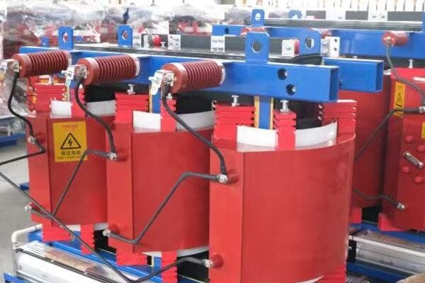
Detailed Comparison of Voltage and Capacity Ranges
Let’s break down the voltage and capacity ranges for both transformer types:
| Characteristic | Power Transformer | Distribution Transformer |
|---|---|---|
| Voltage Range | 33kV – 765kV+ | 400V – 33kV |
| Typical Capacity | 10 MVA – 1000+ MVA | 5 kVA – 2500 kVA |
| Common Applications | Power plants, Substations | Residential, Commercial, Light Industrial |
Power Transformer Voltage and Capacity
Power transformers are designed for high-voltage, high-capacity applications:
-
Voltage Levels:
- Primary: Often 132kV, 220kV, 400kV, or higher
- Secondary: Typically 33kV, 66kV, or 132kV
-
Capacity Range:
- Small: 10 MVA – 50 MVA
- Medium: 50 MVA – 200 MVA
- Large: 200 MVA – 1000+ MVA
I once worked on a project for a major hydroelectric plant where we installed a 500 MVA, 22kV/400kV step-up transformer. The sheer size and capacity of this unit were awe-inspiring, highlighting the critical role these transformers play in our power infrastructure.
Distribution Transformer Voltage and Capacity
Distribution transformers handle the final voltage step-down for end-user consumption:
-
Voltage Levels:
- Primary: Often 11kV or 33kV
- Secondary: Typically 400V/230V for three-phase systems
-
Capacity Range:
- Small: 5 kVA – 100 kVA (residential, small commercial)
- Medium: 100 kVA – 1000 kVA (larger commercial, light industrial)
- Large: 1000 kVA – 2500 kVA (industrial, large commercial complexes)
During a recent urban development project, we deployed multiple 1000 kVA, 11kV/400V distribution transformers throughout the area. These units efficiently powered everything from residential blocks to shopping centers, showcasing the versatility of distribution transformers in meeting diverse local power needs.
Choosing the Right Range for Your Project
When selecting the appropriate voltage and capacity range, consider:
-
Grid Connection Point:
- High-voltage transmission? → Power Transformer
- Local distribution network? → Distribution Transformer
-
Load Requirements:
- Large, constant load (e.g., industrial plant)? → Consider Power Transformer
- Variable, smaller loads (e.g., residential area)? → Distribution Transformer
-
Future Expansion:
- Always factor in potential load growth
- Easier to upgrade distribution transformers than power transformers
-
Regulatory Requirements:
- Ensure compliance with local grid codes and standards
In my experience, the key to selecting the right voltage and capacity range lies in thoroughly understanding your current needs and future projections. I recall a project where a client initially underestimated their future power requirements. By carefully analyzing their growth plans, we were able to recommend a slightly larger capacity transformer that accommodated their expansion without needing an expensive upgrade just a few years later.
Remember, while these ranges provide a general guideline, each project has unique requirements. Always consult with experienced electrical engineers or transformer manufacturers to ensure you’re making the best choice for your specific application. By carefully considering your voltage and capacity needs, you can select a transformer that not only meets your current requirements but also provides the flexibility and efficiency to support your power system well into the future.
Load Behavior and Usage Scenarios?
Are you unsure how different load behaviors impact your choice between power and distribution transformers? Understanding load patterns and usage scenarios is crucial for selecting the right transformer, but many find this aspect confusing. How do you match transformer characteristics to your specific load requirements?
Power transformers are designed for constant, high loads typical in transmission systems and large industrial applications. Distribution transformers handle variable loads common in commercial and residential settings. Your choice depends on load consistency, peak demands, and daily fluctuations. Matching transformer type to load behavior ensures optimal efficiency and longevity of your power system.
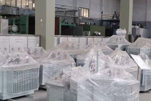
Understanding Load Behavior and Usage Scenarios
Let’s explore how load behavior influences transformer selection:
- Constant vs. Variable Loads
- Peak Load Considerations
- Daily Load Fluctuations
- Specific Usage Scenarios
Constant vs. Variable Loads
-
Power Transformers:
- Designed for constant, high loads
- Optimal efficiency at 80-90% of rated capacity
- Typical in power plants, substations, large industrial facilities
-
Distribution Transformers:
- Built to handle variable loads efficiently
- Maintain good efficiency across a range of load levels
- Common in residential areas, commercial buildings, small industries
I once worked on a project for a steel mill where we installed a 100 MVA power transformer. The constant high load from the electric arc furnaces made a power transformer the ideal choice, as it could efficiently handle the steady, high-power demand.
Peak Load Considerations
Understanding peak loads is crucial for proper sizing:
| Transformer Type | Peak Load Handling |
|---|---|
| Power Transformer | Designed for sustained peak loads |
| Distribution Transformer | Can handle short-term overloads, but less suited for constant peaks |
In a recent commercial development project, we opted for multiple smaller distribution transformers instead of one large unit. This approach allowed us to better manage peak loads during business hours while maintaining efficiency during off-peak times.
Daily Load Fluctuations
-
Power Transformers:
- Less affected by daily fluctuations
- Often operate at near-constant load
-
Distribution Transformers:
- Designed to handle daily load variations efficiently
- Load may vary significantly from day to night
Specific Usage Scenarios
Let’s look at some common scenarios and the recommended transformer type:
-
Large Industrial Facility:
- Scenario: Constant high power demand, 24/7 operation
- Recommendation: Power Transformer
- Example: 50 MVA, 132kV/33kV for a chemical plant
-
Residential Neighborhood:
- Scenario: Variable load, peak during evenings
- Recommendation: Distribution Transformer
- Example: 500 kVA, 11kV/400V pad-mounted unit
-
Office Complex:
- Scenario: Moderate load, peaks during work hours
- Recommendation: Distribution Transformer
- Example: 2000 kVA, 33kV/400V dry-type transformer
-
Renewable Energy Plant:
- Scenario: Variable generation, high capacity
- Recommendation: Power Transformer for grid connection
- Example: 100 MVA, 33kV/220kV for a large solar farm
-
Hospital:
- Scenario: Critical loads, need for reliability
- Recommendation: Multiple Distribution Transformers for redundancy
- Example: 3 x 1500 kVA, 11kV/400V units
In my experience, carefully analyzing load behavior is crucial for optimal transformer selection. I recall a project where a data center initially considered a single large power transformer. After studying their load profile, which showed significant variations based on server usage, we recommended a modular approach with multiple distribution transformers. This solution provided better efficiency across varying loads and enhanced reliability through redundancy.
When considering load behavior and usage scenarios, keep these key points in mind:
- Analyze historical load data if available
- Consider future growth and potential load changes
- Factor in seasonal variations in power demand
- Evaluate the criticality of the load for reliability planning
By thoroughly understanding your load behavior and specific usage scenario, you can select a transformer that not only meets your current needs but also provides the flexibility and efficiency to support your power system as it evolves. Remember, the right choice balances immediate requirements with long-term operational efficiency and reliability.
Installation and Maintenance Considerations?
Are you grappling with the complexities of transformer installation and maintenance? Many project managers and engineers find this aspect challenging, especially when comparing power and distribution transformers. But how do these considerations differ, and why are they crucial for your project’s success?
Power transformers typically require large, secure substations with specialized foundations and cooling systems. Their maintenance is complex and infrequent. Distribution transformers are more flexible, often installed on poles, pads, or in buildings, with simpler, more frequent maintenance needs. Understanding these differences is key to proper planning, budgeting, and long-term system reliability.
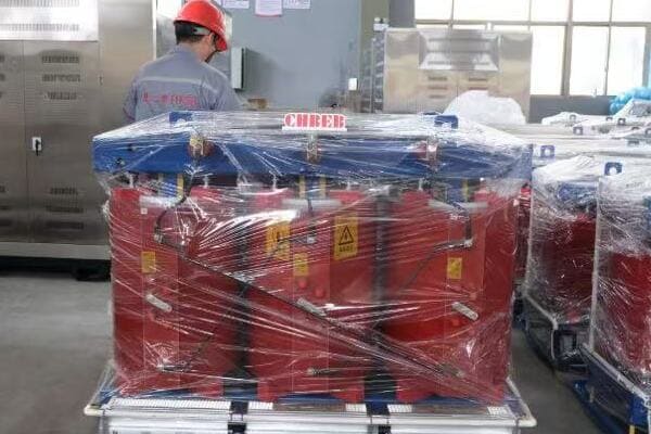
Key Installation and Maintenance Factors
Let’s explore the critical aspects of installation and maintenance for both transformer types:
- Installation Requirements
- Space and Location Considerations
- Cooling and Environmental Factors
- Maintenance Frequency and Complexity
- Lifespan and Replacement Strategies
Installation Requirements
-
Power Transformers:
- Require large, secure substations
- Need robust foundations due to heavy weight
- Often involve complex transportation logistics
- Typically outdoor installations with extensive safety measures
-
Distribution Transformers:
- More flexible installation options (pole-mounted, pad-mounted, indoor)
- Lighter weight allows for easier transportation and installation
- Can be installed closer to end-users
I once managed a project installing a 200 MVA power transformer in a new substation. The process involved specialized heavy transport, a 500-ton crane, and extensive site preparation. In contrast, a recent urban renewal project involved installing multiple 1000 kVA distribution transformers, which we could easily position using standard equipment.
Space and Location Considerations
| Aspect | Power Transformer | Distribution Transformer |
|---|---|---|
| Typical Location | Substations, power plants | Near end-users, urban areas |
| Space Required | Large area, often fenced | Compact, can fit in small spaces |
| Proximity to Load | Can be distant from load centers | Installed close to load points |
Cooling and Environmental Factors
-
Power Transformers:
- Often use sophisticated cooling systems (ONAN, ONAF, OFAF)
- Require consideration of oil containment for environmental protection
- Need to account for noise levels in location planning
-
Distribution Transformers:
- Many use simpler cooling methods (AN, ONAN)
- Dry-type options available for indoor or environmentally sensitive areas
- Generally quieter operation, suitable for residential areas
During a recent project in a densely populated area, we opted for dry-type distribution transformers to address environmental concerns and reduce fire risks, showcasing the flexibility these units offer in challenging installation environments.
Maintenance Frequency and Complexity
-
Power Transformers:
- Require less frequent but more complex maintenance
- Often involve specialized technicians and equipment
- Typical maintenance includes oil testing, winding resistance measurements, and insulation tests
-
Distribution Transformers:
- Need more frequent but simpler maintenance
- Can often be serviced by general electrical maintenance staff
- Maintenance typically includes visual inspections, basic electrical tests, and cleaning
I recall a comprehensive maintenance operation on a large power transformer that took a team of specialists several days to complete. In contrast, the routine checks on distribution transformers in the same network were often completed in a matter of hours by local technicians.
Lifespan and Replacement Strategies
-
Power Transformers:
- Longer lifespan, typically 30-40 years or more with proper maintenance
- Replacement is a major project, often requiring extensive planning and downtime
-
Distribution Transformers:
- Shorter lifespan, usually 20-30 years
- Easier to replace, often with minimal disruption to the power supply
Key considerations for long-term planning:
- Budget for regular maintenance to extend lifespan
- Plan for eventual replacement, especially for distribution transformers
- Consider future load growth in initial transformer selection
In my experience, the key to successful transformer installation and maintenance lies in thorough planning and understanding the specific requirements of each type. For a recent industrial park project, we developed a comprehensive maintenance schedule that balanced the needs of the main power transformer with the more numerous distribution units. This approach ensured optimal performance across the entire system while minimizing downtime and maintenance costs.
Remember, while power transformers may require more intensive installation and maintenance procedures, their longevity and capacity make them crucial for large-scale operations. Distribution transformers, with their flexibility and easier maintenance, are ideal for dynamic, growing networks closer to end-users. By carefully considering these installation and maintenance factors, you can ensure your transformer choice not only meets your immediate power needs but also aligns with your long-term operational and maintenance capabilities.
Project-Based Selection: Matching Transformer Type to Application?
Are you struggling to determine whether a power or distribution transformer is best for your specific project? This decision can be daunting, especially when considering the diverse range of applications in modern power systems. But what if you had a clear guide to help you match transformer types to common project scenarios?
Selecting the right transformer depends on your project’s specific requirements. Power transformers are ideal for large-scale industrial facilities, utility-scale renewable energy projects, and high-voltage transmission systems. Distribution transformers suit commercial buildings, residential areas, and smaller industrial applications. Understanding your project’s voltage needs, load profile, and location is key to making the right choice.

Project Scenarios and Transformer Recommendations
Let’s explore common project types and the transformer choices that best suit them:
- Large Industrial Facilities
- Utility-Scale Renewable Energy Projects
- Urban Development and Commercial Complexes
- Residential Areas
- Data Centers and Critical Infrastructure
Large Industrial Facilities
Scenario: Heavy manufacturing, steel mills, chemical plants
Recommendation: Power Transformers
Rationale:
- High power demands (often >10 MVA)
- Constant, heavy loads
- Often require high voltage (e.g., 132kV) stepped down to medium voltage (e.g., 33kV)
Example: For a large aluminum smelter project, we installed a 100 MVA, 220kV/33kV power transformer. This unit efficiently handled the enormous power demands of the electrolysis process, providing reliable, high-capacity power supply crucial for 24/7 operations.
Utility-Scale Renewable Energy Projects
Scenario: Large solar farms, offshore wind farms
Recommendation: Power Transformers for grid connection, Distribution Transformers for internal networks
Rationale:
- High total capacity, but variable generation
- Need to step up voltage for long-distance transmission
- Internal power distribution within the facility
Example: In a recent 500 MW solar farm project, we used a 300 MVA, 33kV/400kV power transformer for the main grid connection. Additionally, we installed multiple 2500 kVA distribution transformers throughout the site to manage the internal power collection and distribution network.
Urban Development and Commercial Complexes
Scenario: Office buildings, shopping malls, mixed-use developments
Recommendation: Distribution Transformers
Rationale:
- Moderate power needs (typically <5 MVA per building)
- Variable load profiles
- Need for compact, often indoor installations
Example: For a new urban commercial complex, we implemented a network of 2000 kVA, 11kV/400V dry-type distribution transformers. These units were strategically placed in basement electrical rooms, providing efficient power distribution while meeting strict fire safety regulations.
Residential Areas
Scenario: Suburban neighborhoods, apartment complexes
Recommendation: Distribution Transformers
Rationale:
- Lower power requirements (often <1 MVA per transformer)
- Highly variable loads
- Need for quiet operation and aesthetic considerations
Example: In a recent suburban development project, we installed multiple 500 kVA, 11kV/400V pad-mounted distribution transformers. These units were discreetly placed throughout the neighborhood, efficiently handling the varying loads typical of residential areas while blending into the landscape.
Data Centers and Critical Infrastructure
Scenario: Large data centers, hospitals, airports
Recommendation: Combination of Power and Distribution Transformers
Rationale:
- High power needs with critical reliability requirements
- Mix of constant base loads and variable peak loads
- Need for redundancy and power quality management
Example: For a major data center project, we implemented a dual approach. We installed a 50 MVA, 132kV/11kV power transformer for the main supply, complemented by multiple 2500 kVA, 11kV/400V distribution transformers throughout the facility. This configuration provided the necessary high-capacity input while allowing for flexible, redundant power distribution to server rooms and cooling systems.
Selection Checklist
When choosing between power and distribution transformers for your project, consider these factors:
- [ ] Total power requirement (kVA/MVA)
- [ ] Input and output voltage levels
- [ ] Load profile (constant vs. variable)
- [ ] Space constraints and installation environment
- [ ] Reliability and redundancy needs
- [ ] Future expansion plans
- [ ] Environmental factors (noise, EMF, oil containment)
- [ ] Maintenance capabilities and resources
- [ ] Budget constraints (initial cost vs. long-term efficiency)
- [ ] Compliance with local regulations and grid requirements
In my experience, the key to successful project-based transformer selection lies in thoroughly understanding not just the immediate power needs, but also the long-term operational context of the project. I recall a hospital expansion project where the initial plan called for a single large power transformer. After careful analysis of their critical power needs and future growth plans, we recommended a combination of a smaller power transformer and multiple distribution units. This approach provided better redundancy, flexibility for future expansion, and improved energy efficiency across varying load conditions.
Remember, while these guidelines provide a solid starting point, each project has unique characteristics that may influence your choice. Always consult with experienced electrical engineers and transformer manufacturers to ensure your selection aligns perfectly with your specific project requirements. By carefully matching transformer types to your application, you can ensure optimal performance, reliability, and cost-effectiveness for your power system.
Summary Table: Power vs Distribution Transformer at a Glance?
Are you looking for a quick, comprehensive comparison between power and distribution transformers? It can be challenging to keep all the differences in mind, especially when making crucial decisions for your power system projects. But what if you had a clear, concise summary of all the key points we’ve discussed?
Power transformers handle high voltages (33kV-765kV) for transmission, while distribution transformers manage lower voltages (400V-33kV) for local use. They differ in capacity, load type, cooling methods, and maintenance needs. This summary table provides a quick reference for engineers and project managers to guide transformer selection based on specific project requirements.

Comprehensive Comparison Table
Let’s summarize the key differences in a detailed comparison table:
| Parameter | Power Transformer | Distribution Transformer |
|---|---|---|
| Voltage Level | 33kV – 765kV | 400V – 33kV |
| Capacity Range | 10 MVA – 1000+ MVA | 5 kVA – 2500 kVA |
| Load Type | Constant, high load | Variable load |
| Usage | Generation → Transmission | Local distribution |
| Cooling Type | ONAN, ONAF, OFAF | AN, ONAN |
| Installation | Large substations | Pole, Pad, Indoor |
| Maintenance | Complex, less frequent | Simpler, more frequent |
| Efficiency Focus | High at full load | Balanced across load range |
| Size and Weight | Large and heavy | Compact and lighter |
| Core Design | Complex, custom | Simpler, often standardized |
| Winding Material | Typically copper | Copper or aluminum |
| Insulation | Oil and paper (usually) | Oil, dry-type, or resin |
| Monitoring | Advanced, continuous | Basic, often manual checks |
| Lifespan | 30-40+ years | 20-30 years |
| Cost | High initial, high maintenance | Lower initial, moderate maintenance |
| Typical Applications | Power plants, Grid transmission | Buildings, Local industry |
Key Insights from the Comparison
-
Voltage and Capacity:
The most obvious difference lies in the voltage and capacity ranges, reflecting their distinct roles in the power system. -
Load Handling:
Power transformers excel in constant, high-load scenarios, while distribution transformers are designed for variable loads typical in end-user applications. -
Installation and Maintenance:
Power transformers require specialized installations and maintenance, whereas distribution transformers offer more flexibility and simpler maintenance routines. -
Efficiency and Design:
Power transformers are optimized for high efficiency at full load, with complex designs. Distribution transformers balance efficiency across varying loads with more standardized designs. -
Cost and Lifespan:
While power transformers have higher upfront and maintenance costs, their longer lifespan can make them more economical for high-capacity, critical installations over time.
In my experience, this summary table has been an invaluable tool in discussions with clients and team members. I recall a project meeting where we were debating the best transformer choice for a new industrial park. By referencing a similar table, we quickly identified that the park’s diverse power needs and potential for future expansion were better served by a combination of a central power transformer and multiple distribution units, rather than trying to use a single transformer type for all applications.
When using this table to guide your decision-making process, consider:
- Your project’s specific voltage and capacity requirements
- The expected load profile and variability
- Installation constraints and environmental factors
- Long-term maintenance capabilities and resources
- Future expansion plans and flexibility needs
Remember, while this summary provides a quick reference, each project has unique characteristics that may require more nuanced consideration. Always consult with experienced electrical engineers or transformer manufacturers for tailored advice on your specific application.
By keeping these key differences in mind and using this table as a starting point, you’ll be better equipped to make informed decisions in your power system designs, whether you’re working on large-scale transmission projects or local distribution networks.
Conclusion
Choosing between power and distribution transformers depends on various factors including voltage levels, capacity needs, load profiles, and installation environments. By understanding these differences and considering project-specific requirements, engineers and project managers can select the most suitable transformer type, ensuring optimal performance, efficiency, and reliability in their power systems.
Remember, at chbeb-ele, we’re not just sharing information – we’re empowering you to be part of the solution in creating a secure, clean, and efficient energy future. Let’s continue this journey together.
