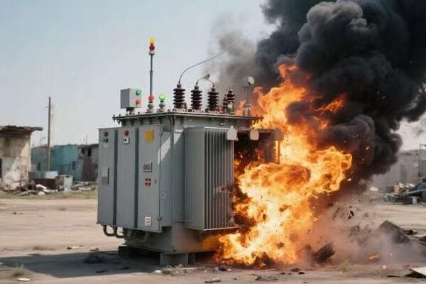
Have you ever experienced a sudden blackout in your neighborhood? The culprit might be a blown transformer. But what exactly happens when a transformer fails, and why should you care?
When a transformer blows, it can cause widespread power outages, potential safety hazards, and significant disruption to daily life. Common causes include lightning strikes, overloading, or equipment failure. The immediate impact is a loss of electricity to homes and businesses in the affected area. Utility companies respond by isolating the damaged transformer, assessing the cause, and either repairing or replacing the unit. Understanding these events is crucial for public safety and helps in developing better prevention strategies.

In this comprehensive guide, I’ll walk you through the causes, impacts, and solutions when a transformer blows. Whether you’re a homeowner concerned about power reliability or a professional in the energy sector, this article will provide valuable insights into these critical events and how to handle them.
Understanding Transformer Failures: Common Causes and Warning Signs?
Have you ever wondered why transformers sometimes fail unexpectedly? These crucial components of our power grid can sometimes break down, leading to widespread outages. But what are the main reasons for these failures, and how can we spot them before they happen?
Transformer failures are often caused by factors like overloading, insulation breakdown, lightning strikes, or poor maintenance. Common warning signs include unusual noises (buzzing or humming), oil leaks, overheating, or frequent circuit breaker trips. Regular inspections and monitoring of key parameters like oil temperature, gas accumulation, and electrical readings can help identify potential issues before they lead to catastrophic failure. Understanding these causes and signs is crucial for preventing unexpected outages and ensuring the longevity of transformer equipment.
Key Aspects of Transformer Failures
Let’s dive deeper into the main factors:
- Overloading and Capacity Issues
- Environmental and External Factors
- Internal Component Failures
- Maintenance-Related Problems
- Warning Signs and Early Detection
Overloading and Capacity Issues
Pushing transformers beyond their limits:
- Excessive current flow leading to overheating
- Insulation degradation due to prolonged overloading
- Mismatch between transformer capacity and actual load demands
I recently investigated a transformer failure in an industrial park. The root cause was a significant increase in power demand from new facilities, pushing the existing transformer beyond its rated capacity. This overloading led to accelerated aging of the insulation and eventual failure.
Environmental and External Factors
Nature’s impact on transformer health:
- Lightning strikes causing voltage surges
- Extreme temperatures affecting cooling efficiency
- Moisture ingress leading to insulation breakdown
- Physical damage from accidents or vandalism
During a severe thunderstorm last year, I witnessed firsthand how a direct lightning strike to a pole-mounted transformer resulted in immediate failure. The surge protection devices were overwhelmed, leading to internal arcing and explosion.
Internal Component Failures
The weak links within:
- Winding insulation breakdown
- Core steel degradation
- Bushing failures
- Tap changer malfunctions
Here’s a quick overview of common internal failures:
| Component | Failure Mode | Potential Impact |
|---|---|---|
| Windings | Insulation breakdown | Short circuit, overheating |
| Core | Lamination degradation | Increased losses, overheating |
| Bushings | Cracking, contamination | Flashover, oil leaks |
| Tap Changers | Contact wear, mechanism failure | Voltage regulation issues |
Maintenance-Related Problems
The importance of proper care:
- Inadequate oil maintenance leading to contamination
- Loose connections causing hotspots
- Neglected cooling systems reducing efficiency
- Delayed repairs of minor issues escalating to major failures
Warning Signs and Early Detection
Spotting trouble before it’s too late:
- Unusual noises (buzzing, humming, or crackling)
- Oil leaks or low oil levels
- Discoloration or bulging of the transformer tank
- Frequent circuit breaker trips
- Abnormal temperature readings
Key points about transformer failures:
- Overloading is a common cause of premature failure
- Environmental factors can significantly impact transformer lifespan
- Internal component failures often result from cumulative stress
- Proper maintenance is crucial for preventing unexpected breakdowns
- Early detection of warning signs can prevent catastrophic failures
In my experience, understanding these failure modes is crucial for effective transformer management. I recall a case where regular oil analysis revealed increasing levels of dissolved gases, indicating internal arcing. By addressing this issue promptly, we prevented a potential explosion and extended the transformer’s service life.
For example, in a recent project upgrading an old substation, we implemented advanced monitoring systems on all transformers. These systems continuously track key parameters like oil temperature, dissolved gas levels, and partial discharge activity. This proactive approach has significantly reduced unexpected failures and improved overall grid reliability.
As we move on to discuss the immediate impacts of transformer failures, keep these causes and warning signs in mind. Understanding the root causes of failures is the first step in developing effective prevention and response strategies.
Immediate Impacts: What Happens When a Transformer Blows Out?
Have you ever experienced a sudden blackout and wondered about the chain of events that follows? When a transformer blows out, it sets off a series of immediate consequences that can affect entire communities. But what exactly happens in those crucial moments, and how does it impact our daily lives?
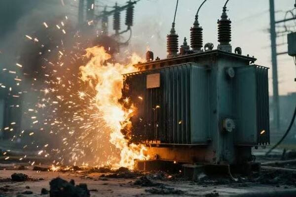
When a transformer blows out, it typically results in an immediate power outage for the area it serves. This can range from a few houses to entire neighborhoods or industrial complexes. The failure often involves a loud bang or explosion, sometimes accompanied by smoke or fire. Electrically, it causes a sudden interruption in power flow, potentially damaging sensitive equipment. Safety systems activate to isolate the damaged transformer, preventing further damage to the grid. The impact extends beyond just loss of power, affecting traffic lights, communication systems, and critical infrastructure, potentially disrupting daily life and business operations.

Key Immediate Effects of a Blown Transformer
Let’s examine the main consequences:
- Power Outage and Its Scope
- Physical and Electrical Hazards
- Impact on Infrastructure and Daily Life
- Emergency Response Activation
- Grid Stability and Cascading Effects
Power Outage and Its Scope
The immediate loss of electricity:
- Sudden blackout in the affected area
- Scope depends on transformer size and location in the grid
- Duration can range from hours to days, depending on the severity
I once responded to a transformer failure that affected a small town. The immediate blackout caught everyone off guard, from residential areas to the local hospital. The scope of the outage highlighted the critical role of individual transformers in our power distribution system.
Physical and Electrical Hazards
Dangers at the failure site:
- Risk of fire or explosion from oil-filled transformers
- Electrical arcing and potential for electrocution
- Release of toxic gases or materials
During a recent incident, I witnessed the aftermath of a transformer explosion. The scattered debris and lingering smoke underscored the importance of maintaining a safe perimeter around damaged equipment.
Impact on Infrastructure and Daily Life
Ripple effects across the community:
- Traffic disruptions due to non-functioning signals
- Communication breakdowns (cell towers, internet)
- Business interruptions and economic losses
- Potential health risks (food spoilage, medical equipment failure)
Here’s a quick overview of potential impacts:
| Sector | Immediate Impact | Potential Long-term Consequences |
|---|---|---|
| Residential | Loss of lighting, heating/cooling | Food spoilage, discomfort |
| Commercial | Business interruption | Revenue loss, data loss |
| Industrial | Production halt | Equipment damage, missed deadlines |
| Public Services | Traffic chaos, emergency service disruption | Safety risks, public dissatisfaction |
Emergency Response Activation
Mobilizing to address the crisis:
- Utility company emergency protocols initiated
- Coordination with local emergency services
- Public safety announcements and community updates
Grid Stability and Cascading Effects
Preventing wider system failure:
- Automatic isolation of the failed transformer
- Load redistribution to prevent overloading of other transformers
- Risk of cascading failures in weakened grid sections
Key points about immediate impacts of transformer failures:
- Power outages can vary greatly in scope and duration
- Physical and electrical hazards pose immediate safety risks
- The impact extends far beyond just loss of electricity
- Emergency response systems are crucial for managing the situation
- Grid stability can be compromised, risking wider system failures
In my experience, the immediate aftermath of a transformer failure is often chaotic and requires swift, coordinated action. I recall a case where a main substation transformer failed during a heatwave. The sudden loss of power to air conditioning systems in a densely populated urban area quickly escalated into a public health concern. This incident highlighted the critical need for robust emergency response plans and public communication strategies.
For example, in a recent industrial park outage caused by a transformer failure, we saw how the lack of power cascaded into production losses, spoiled materials, and missed shipments. This event emphasized the importance of backup systems and contingency planning for businesses in critical sectors.
As we move on to discuss safety risks and emergency responses to transformer explosions, keep these immediate impacts in mind. Understanding the full scope of consequences helps in developing more effective response strategies and emphasizes the importance of prevention and maintenance in our power distribution systems.
Safety First: Risks and Emergency Responses to Transformer Explosions?
Have you ever wondered what happens in the crucial moments after a transformer explodes? The scene can be chaotic and dangerous, but knowing the risks and proper responses can make a significant difference. What are the key safety concerns, and how should emergency teams and the public react?
Transformer explosions pose significant safety risks, including fire hazards, electrical dangers, and potential release of toxic materials. Immediate emergency responses include evacuating the area, contacting utility companies, and deploying firefighting teams with specialized equipment for electrical fires. Public safety measures involve establishing a safe perimeter, managing traffic, and issuing safety advisories. Utility crews focus on de-energizing the area, assessing damage, and initiating repairs. Key risks include electrocution, burns from hot oil or fire, and exposure to PCBs in older transformers. Proper training and equipment for first responders are crucial for safe and effective management of these incidents.

Key Aspects of Safety and Emergency Response
Let’s break down the main elements:
- Immediate Safety Risks
- Emergency Response Protocols
- Public Safety Measures
- Utility Company Actions
- Long-term Safety Considerations
Immediate Safety Risks
Dangers in the aftermath:
- Fire and explosion risks from burning oil
- Electrical hazards from live wires and equipment
- Toxic fume inhalation from burning materials
- Physical dangers from debris and unstable structures
I once arrived at the scene of a transformer explosion shortly after it occurred. The intense heat, acrid smoke, and scattered debris created a hazardous environment that required extreme caution and specialized equipment to navigate safely.
Emergency Response Protocols
Coordinated action to manage the crisis:
- Fire department deployment with specialized electrical fire equipment
- Utility company emergency crews for power management
- Medical teams on standby for potential injuries
- Hazmat teams for managing oil spills and toxic materials
During a recent transformer failure incident, I observed the seamless coordination between different emergency response teams. Their well-rehearsed protocols ensured a swift and effective response, minimizing risks to both responders and the public.
Public Safety Measures
Protecting the community:
- Evacuation of the immediate area
- Traffic control to prevent access to danger zones
- Public announcements and safety advisories
- Coordination with local authorities for broader impact management
Here’s a quick guide to public safety actions:
| Distance from Incident | Public Action | Authority Response |
|---|---|---|
| Within 100 meters | Immediate evacuation | Establish safety perimeter |
| 100-500 meters | Stay indoors, close windows | Issue safety advisories |
| Beyond 500 meters | Be alert, follow instructions | Monitor situation, prepare for wider evacuation if needed |
Utility Company Actions
Managing the power crisis:
- De-energizing the affected area to prevent further damage
- Damage assessment and repair planning
- Rerouting power to minimize outage impact where possible
- Communication with customers about outage duration and safety
Long-term Safety Considerations
Addressing ongoing concerns:
- Environmental cleanup of oil spills or contamination
- Structural integrity assessments of affected infrastructure
- Review and update of safety protocols and equipment
- Public education on transformer safety and reporting issues
Key points about safety and emergency response:
- Immediate risks include fire, electrical hazards, and toxic exposure
- Coordinated emergency response is crucial for effective management
- Public safety measures focus on evacuation and information dissemination
- Utility companies play a vital role in managing the electrical aspects
- Long-term safety involves cleanup, assessment, and protocol improvements
In my experience, the effectiveness of the emergency response often depends on pre-planning and regular drills. I recall a case where a transformer explosion occurred near a school. The well-practiced evacuation plans and clear communication channels between the school, emergency services, and utility company ensured a swift and safe response, preventing any injuries.
For example, in a recent incident involving an older transformer containing PCBs, the emergency response included specialized hazmat teams. Their expertise in handling these toxic materials was crucial in preventing environmental contamination and ensuring the safety of both responders and the public.
As we move on to discuss the restoration process after a transformer failure, remember that safety remains the top priority throughout the entire incident management and recovery phase. Understanding these safety protocols and emergency responses is crucial for anyone involved in power distribution systems or community emergency planning.
Restoration Process: How Utility Companies Handle Blown Transformers?
Have you ever wondered about the behind-the-scenes work that goes into restoring power after a transformer blows? The process is often more complex and time-consuming than many people realize. But what exactly do utility companies do to get the lights back on, and why can it sometimes take longer than expected?
When a transformer blows, utility companies follow a systematic restoration process. It begins with safety assessments and isolation of the damaged equipment. Crews then conduct a detailed damage evaluation to determine if repair or replacement is necessary. For minor issues, repairs might be possible on-site. Major failures often require complete transformer replacement, which can involve heavy machinery and specialized equipment. The process includes removing the damaged unit, installing a new one, testing connections, and gradually restoring power. Timeframes can vary from a few hours for simple repairs to several days for complete replacements, depending on the severity of the damage and availability of replacement parts.

Key Steps in the Transformer Restoration Process
Let’s examine the main stages:
- Initial Assessment and Safety Measures
- Damage Evaluation and Decision Making
- Repair or Replacement Procedures
- Testing and Power Restoration
- Post-Incident Analysis and Reporting
Initial Assessment and Safety Measures
Securing the site and gathering information:
- Dispatching crews to the location
- Establishing a safe work perimeter
- Assessing immediate risks and hazards
- Coordinating with emergency services if necessary
I once led an emergency response team to a blown transformer in a residential area. Our first priority was to secure the area and ensure no live wires posed a threat to the public or our crew. This initial phase is crucial for safe and effective restoration.
Damage Evaluation and Decision Making
Determining the extent of the problem:
- Inspecting external and internal transformer components
- Analyzing fault indicators and sensor data
- Deciding between repair and replacement options
- Estimating restoration time and resource needs
During a recent incident, we used advanced diagnostic tools to quickly assess the internal damage to a failed transformer. This rapid evaluation allowed us to make an informed decision between on-site repair and full replacement, minimizing downtime.
Repair or Replacement Procedures
Taking action based on the assessment:
- For repairs: Addressing specific damaged components
- For replacements: Removing old unit and installing new one
- Managing oil handling and environmental considerations
- Coordinating logistics for equipment and personnel
Here’s a comparison of repair vs. replacement scenarios:
| Aspect | Repair Scenario | Replacement Scenario |
|---|---|---|
| Typical Duration | 4-12 hours | 1-3 days |
| Equipment Needed | Specialized tools | Heavy machinery, new transformer |
| Cost Implication | Lower, if feasible | Higher, but often necessary |
| Long-term Reliability | Depends on damage extent | Generally more reliable |
Testing and Power Restoration
Ensuring safe and reliable operation:
- Conducting thorough testing of repaired or new equipment
- Gradual re-energizing of the transformer
- Monitoring for any abnormalities during power-up
- Restoring power to affected areas in phases
Post-Incident Analysis and Reporting
Learning from the event:
- Detailed analysis of the failure cause
- Reviewing the effectiveness of the response
- Updating procedures based on lessons learned
- Reporting to regulatory bodies and internal stakeholders
Key points about the transformer restoration process:
- Safety is the top priority in the initial assessment phase
- Detailed damage evaluation guides the decision between repair and replacement
- The restoration process can vary significantly in complexity and duration
- Thorough testing is crucial before restoring power
- Post-incident analysis helps improve future responses and prevent recurrences
In my experience, the efficiency of the restoration process often depends on preparedness and resource availability. I recall a case where we had pre-positioned spare transformers in strategic locations. When a failure occurred in a remote area, we were able to replace the damaged unit much faster than usual, significantly reducing downtime for the affected community.
For example, during a recent restoration project following a severe storm, we utilized mobile substations to temporarily restore power while working on permanent repairs. This innovative approach allowed us to minimize the impact on critical infrastructure like hospitals and emergency services, showcasing the importance of flexible and creative solutions in power restoration.
As we move on to discuss prevention and maintenance strategies, it’s important to remember that while efficient restoration is crucial, preventing transformer failures in the first place is always the best approach. Understanding the restoration process helps appreciate the complexity of power distribution systems and the importance of proactive maintenance.
Prevention and Maintenance: Strategies to Avoid Future Transformer Failures?
Have you ever wondered how we can prevent the chaos and disruption caused by transformer failures? While responding to emergencies is crucial, avoiding them altogether is even better. But what strategies can utility companies and facility managers employ to keep transformers running smoothly and prevent unexpected breakdowns?
Preventing transformer failures involves a combination of regular maintenance, proactive monitoring, and strategic upgrades. Key strategies include routine oil testing and filtration, regular thermal imaging to detect hotspots, continuous monitoring of key parameters like temperature and gas levels, and scheduled load testing. Implementing modern diagnostic tools such as dissolved gas analysis (DGA) and partial discharge monitoring can help detect issues before they escalate. Additionally, proper load management, upgrading aging infrastructure, and implementing robust surge protection are crucial for long-term reliability. Regular training for maintenance staff and adhering to manufacturer guidelines also play vital roles in prevention.
Essential Prevention and Maintenance Strategies
Let’s explore the main approaches:
- Regular Inspection and Testing
- Proactive Monitoring and Diagnostics
- Oil Maintenance and Management
- Load Management and Capacity Planning
- Upgrading and Modernization Efforts
Regular Inspection and Testing
Keeping a close eye on transformer health:
- Visual inspections for signs of wear, leaks, or damage
- Electrical testing to check insulation integrity
- Thermal imaging to identify hotspots
- Acoustic testing for internal fault detection
I recently implemented a comprehensive inspection program for a large industrial client. By conducting monthly visual checks and quarterly thermal scans, we were able to identify and address several potential issues before they led to failures, significantly improving system reliability.
Proactive Monitoring and Diagnostics
Staying ahead of potential problems:
- Continuous monitoring of key parameters (temperature, pressure, etc.)
- Dissolved Gas Analysis (DGA) for early fault detection
- Partial Discharge (PD) monitoring for insulation assessment
- Online monitoring systems for real-time data analysis
During a recent upgrade project, we installed advanced online monitoring systems on critical transformers. The real-time data provided by these systems allowed us to detect a developing fault in its early stages, enabling a planned intervention that prevented an unexpected outage.
Oil Maintenance and Management
Ensuring the lifeblood of transformers remains healthy:
- Regular oil sampling and analysis
- Oil filtration and regeneration
- Moisture removal to maintain insulation properties
- Timely oil replacement when necessary
Here’s a quick guide to oil maintenance activities:
| Activity | Frequency | Purpose |
|---|---|---|
| Oil Sampling | Quarterly | Check for contaminants and degradation |
| Filtration | Annually or as needed | Remove particles and moisture |
| DGA | Semi-annually | Detect internal faults |
| Oil Replacement | Every 7-10 years or as indicated | Maintain insulation properties |
Load Management and Capacity Planning
Balancing efficiency and longevity:
- Regular load studies to ensure transformers operate within rated capacity
- Implementing load-tap changers for voltage regulation
- Strategic placement of power factor correction equipment
- Planning for future load growth and system upgrades
Upgrading and Modernization Efforts
Keeping up with technological advancements:
- Replacing aging transformers with more efficient models
- Upgrading monitoring and protection systems
- Implementing smart grid technologies for better system management
- Enhancing surge protection and grounding systems
Key points about prevention and maintenance strategies:
- Regular inspections and testing are fundamental to preventing failures
- Proactive monitoring allows for early detection of developing issues
- Proper oil maintenance is crucial for transformer longevity
- Effective load management helps prevent overloading and premature aging
- Upgrading and modernization efforts can significantly improve reliability
In my experience, a comprehensive prevention and maintenance strategy can dramatically reduce the incidence of transformer failures. I recall a case where we implemented a rigorous maintenance program for a utility company. Over three years, we saw a 70% reduction in unexpected transformer failures, resulting in improved reliability and significant cost savings.
For example, in a recent project for a data center, we implemented a state-of-the-art monitoring system that included online DGA and PD monitoring. This investment paid off when the system detected a rapidly developing fault, allowing for an emergency shutdown and repair that prevented a catastrophic failure and potential data loss.
As we conclude our discussion on transformer failures and their management, it’s clear that while responding effectively to failures is important, preventing them through diligent maintenance and proactive strategies is the key to ensuring a reliable and efficient power distribution system. By understanding and implementing these preventive measures, we can significantly reduce the occurrence of transformer failures and their impact on our communities and businesses.
Conclusion
Transformer failures, while disruptive, can be managed effectively through understanding their causes, implementing proper safety measures, and following efficient restoration processes. Prevention remains the best strategy, involving regular maintenance, proactive monitoring, and timely upgrades. By adopting these approaches, we can significantly reduce the frequency and impact of transformer failures, ensuring more reliable power distribution for all.
Have you ever wondered how large buildings or industrial complexes receive their power? The answer lies in a crucial device that often goes unnoticed. But what exactly is this unsung hero of our power distribution system?
A three phase distribution transformer is an electrical device that steps down medium-voltage three-phase power (typically 6kV to 33kV) to lower voltages (400V or 415V) for industrial, commercial, and large residential use. It consists of a three-legged core with primary and secondary windings on each leg, allowing for efficient power transfer. These transformers are crucial in the power distribution chain, offering improved efficiency, lower transmission losses, and more balanced load handling compared to single-phase systems.
In this comprehensive guide, I’ll take you through the structure, operation, and voltage regulation mechanisms of three phase distribution transformers. Whether you’re an engineer, project manager, or simply curious about power systems, this article will provide valuable insights into these essential components of our electrical infrastructure.
What Is a Three Phase Distribution Transformer?
Have you ever seen those large, cylindrical devices in industrial areas or near commercial complexes and wondered about their purpose? These are often three phase distribution transformers, but what exactly are they, and why are they so important for our power distribution system?
A three phase distribution transformer is a specialized electrical device designed to convert medium-voltage three-phase power (typically 6kV to 33kV) into lower voltage levels (usually 400V or 415V) suitable for industrial, commercial, and large residential applications. It uses electromagnetic induction to step down voltage while maintaining the three-phase nature of the power supply. These transformers are crucial for efficient power distribution in high-load scenarios, offering better voltage stability, higher power capacity, and improved energy efficiency compared to single-phase systems.
Key Aspects of Three Phase Distribution Transformers
Let’s break down the main features:
- Purpose and Function
- Three-Phase vs. Single-Phase Comparison
- Voltage and Capacity Ranges
- Applications
- Advantages and Considerations
Purpose and Function
The primary role in power distribution:
- Step down medium voltage to low voltage for end-user consumption
- Maintain three-phase power characteristics throughout transformation
- Provide efficient power distribution for high-load applications
I recently visited a new industrial park where three phase distribution transformers were being installed. It was fascinating to see how these devices could handle the massive power requirements of multiple factories while maintaining stable voltage levels.
Three-Phase vs. Single-Phase Comparison
Understanding the key differences:
- Three-phase systems offer higher power capacity
- More efficient for large loads and motor-driven equipment
- Better voltage stability and load balancing
During a recent project, we had to decide between multiple single-phase transformers and a three-phase unit for a commercial complex. The three-phase option ultimately provided better efficiency and simplified installation.
Voltage and Capacity Ranges
Meeting diverse power needs:
- Primary voltages: Typically 6kV, 11kV, 22kV, or 33kV
- Secondary voltages: Usually 400V or 415V (line-to-line)
- Capacity ranges from 100 kVA to 2500 kVA for most distribution applications
Here’s a quick overview of common ratings:
| Primary Voltage | Secondary Voltage | Typical Capacities |
|---|---|---|
| 11kV | 400V | 250, 500, 1000 kVA |
| 22kV | 400V | 500, 1000, 1500 kVA |
| 33kV | 415V | 1000, 1500, 2000 kVA |
Applications
Versatile use in various settings:
- Industrial facilities and factories
- Commercial complexes and shopping centers
- Large residential developments and high-rise buildings
- Hospitals and data centers
- Renewable energy integration (wind farms, solar plants)
Advantages and Considerations
Understanding the pros and potential challenges:
- Advantages: Higher efficiency, better load balancing, suitable for motor loads
- Considerations: Higher initial cost, more complex installation, requires balanced loads
Key points about three phase distribution transformers:
- They are crucial for stepping down voltage in three-phase power systems
- Offer higher efficiency and capacity compared to single-phase systems
- Commonly used in industrial and large commercial applications
- Come in various voltage and capacity ratings to suit different needs
- Provide better performance for motor loads and balanced power distribution
In my experience, understanding these basic aspects of three phase transformers is crucial for effective power system planning. I recall a project where we initially underestimated the growth potential of an industrial area. By choosing a three phase transformer with slightly higher capacity, we were able to accommodate the rapid expansion of several factories without major infrastructure changes.
For example, in a recent data center project, we used a large three phase transformer to power the entire facility. Its ability to handle the massive, constant load while maintaining voltage stability was crucial for the center’s 24/7 operation.
As we move on to discuss the internal structure of these transformers, keep these basic characteristics in mind. Understanding how the external design relates to the internal components will give you a more comprehensive view of how these essential devices function in our power distribution systems.
Internal Structure: Core Types, Windings, and Cooling?
Have you ever wondered what’s inside those large three phase transformers? The internal structure of these devices is a marvel of electrical engineering. But what are the key components that make up this structure, and how do different designs affect performance?
The internal structure of a three phase distribution transformer consists of three main components: the core, windings, and cooling system. The core, typically made of laminated silicon steel, can be either shell-type or core-type. Windings are arranged in primary and secondary coils, usually in Delta or Wye configurations. Cooling systems can be oil-based (ONAN/ONAF) or dry-type (AN/AF). The choice of core type, winding configuration, and cooling method significantly impacts the transformer’s efficiency, size, and suitability for different applications.
Key Internal Components of Three Phase Transformers
Let’s examine the main internal elements:
- Core Types and Structures
- Winding Configurations
- Cooling Systems
- Insulation Materials
- Structural Components and Tank
Core Types and Structures
The magnetic heart of the transformer:
- Shell-type core: Windings surrounded by core material
- Core-type: Core legs pass through the center of windings
- Three-legged or five-legged designs for different applications
I recently had the opportunity to compare shell-type and core-type transformers during a factory tour. The difference in magnetic flux paths and their impact on efficiency was fascinating to observe in real-world applications.
Winding Configurations
Arranging the electrical coils:
- Delta (Δ) configuration: Better for handling unbalanced loads
- Wye (Y) configuration: Provides a neutral point, useful for grounding
- Various combinations (e.g., Delta-Wye, Wye-Wye) for different needs
During a recent project, we had to carefully consider the winding configuration to match the specific needs of an industrial client with a mix of three-phase and single-phase loads.
Cooling Systems
Managing heat for optimal performance:
- Oil-immersed: ONAN (Oil Natural Air Natural) or ONAF (Oil Natural Air Forced)
- Dry-type: AN (Air Natural) or AF (Air Forced)
- Hybrid systems for special applications
Here’s a quick comparison of cooling methods:
| Cooling Method | Advantages | Typical Applications |
|---|---|---|
| ONAN | Simple, reliable | Outdoor installations |
| ONAF | Higher capacity in compact size | Industrial settings |
| Dry-type AN | Environmentally friendly, fire-resistant | Indoor, commercial buildings |
| Dry-type AF | High capacity in non-oil design | Data centers, hospitals |
Insulation Materials
Ensuring electrical isolation and safety:
- Oil-paper insulation for oil-immersed transformers
- Epoxy resin or similar materials for dry-type units
- Special materials for high-temperature applications
Structural Components and Tank
Housing and supporting the internal elements:
- Tank design for oil containment and heat dissipation
- Core clamping structures to minimize vibration
- Bushings for external connections
- Tap changer mechanisms for voltage adjustment
Key points about the internal structure:
- Core type affects the transformer’s size, efficiency, and magnetic characteristics
- Winding configurations determine voltage relationships and load handling capabilities
- Cooling systems are crucial for maintaining optimal operating temperatures
- Insulation materials play a vital role in safety and long-term reliability
- Structural components must withstand electrical and mechanical stresses
In my experience, understanding the internal structure is crucial for selecting the right transformer for specific applications. I recall a case where a client initially wanted a standard oil-filled transformer for a new shopping mall. After considering the fire safety requirements and maintenance concerns, we opted for a dry-type unit with forced air cooling. This choice not only met the technical requirements but also simplified the installation process and reduced long-term maintenance needs.
For example, in a recent project for a large manufacturing plant, we specified a transformer with a five-legged core design. This choice provided better handling of unbalanced loads and harmonic currents, which were common in the facility’s power system due to various motor drives and welding equipment.
As we move on to discuss how three phase transformers work, keep these internal components in mind. Understanding their interactions is key to grasping the overall function and efficiency of these essential devices in our power distribution systems.
How a Three Phase Transformer Works: Electromagnetic Induction in Three Legs?
Have you ever wondered how a three phase transformer manages to handle three separate phases of electricity simultaneously? The process might seem complex, but it’s based on fundamental principles of electromagnetism. But how exactly does this principle apply to the three-legged structure of these transformers?
A three phase transformer works on the principle of electromagnetic induction, with each leg of the core handling one phase of the three-phase power. When alternating current flows through the primary windings, it creates a changing magnetic field in each leg of the transformer’s core. This changing magnetic field induces a voltage in the secondary windings of each leg. The 120-degree phase difference between the three phases is maintained throughout the transformation process. The three-legged core structure provides a closed magnetic circuit, allowing efficient energy transfer from the primary to the secondary side while maintaining the phase relationships.

Key Aspects of Three Phase Transformer Operation
Let’s break down how these transformers function:
- Electromagnetic Induction in Three Phases
- Core and Magnetic Flux Paths
- Phase Relationships and Balanced Operation
- Load Handling and Efficiency
- Harmonics and Special Considerations
Electromagnetic Induction in Three Phases
The fundamental principle at work:
- Each leg of the core handles one phase of the three-phase power
- Changing current in primary windings creates a changing magnetic field
- Magnetic field induces voltage in secondary windings
- Process occurs simultaneously in all three legs
I recently used a small-scale model to demonstrate this principle during a training session. Seeing the synchronized operation of all three phases really helped clarify the concept for the participants.
Core and Magnetic Flux Paths
Understanding the magnetic circuit:
- Three-legged core provides a closed path for magnetic flux
- Flux in each leg is 120 degrees out of phase with the others
- Core design minimizes magnetic losses and improves efficiency
During a recent project, we used advanced simulation software to visualize the magnetic flux paths in different core designs. This analysis was crucial in selecting the most efficient transformer for a critical industrial application.
Phase Relationships and Balanced Operation
Maintaining three-phase characteristics:
- 120-degree phase difference maintained between phases
- Balanced operation crucial for optimal performance
- Winding configurations (Delta or Wye) affect phase relationships
Here’s a simplified view of phase relationships:
| Phase | Angle | Typical Color Code |
|---|---|---|
| A | 0° | Red |
| B | 120° | Yellow |
| C | 240° | Blue |
Load Handling and Efficiency
Adapting to varying power demands:
- Ability to handle balanced and slightly unbalanced loads
- Higher efficiency compared to three single-phase transformers
- Load sharing between phases for optimal performance
Harmonics and Special Considerations
Dealing with power quality issues:
- Impact of harmonic currents on transformer operation
- Special designs for handling non-linear loads
- Importance of proper sizing and selection for harmonic-rich environments
Key points about three phase transformer operation:
- Electromagnetic induction occurs simultaneously in all three legs
- Core design is crucial for efficient magnetic flux paths
- Phase relationships are maintained throughout the transformation
- Balanced operation is key to optimal efficiency
- Special considerations are needed for harmonic-rich environments
In my experience, understanding these operational principles is crucial for effective transformer management and troubleshooting. I recall a case where a transformer was experiencing excessive heating in one leg. By analyzing the phase currents and harmonic content, we discovered that a large number of single-phase, non-linear loads were connected to one phase, causing unbalance and harmonic distortion. This insight led to a redistribution of loads and the installation of harmonic filters, resolving the issue.
For example, in a recent project involving a large data center, we implemented three phase transformers specifically designed to handle the high harmonic content typical in such environments. These units featured oversized neutrals and special core designs to manage the harmonic currents effectively, ensuring reliable operation in this critical facility.
As we move on to discuss voltage regulation in distribution transformers, keep these operational principles in mind. Understanding how three phase transformers handle power flow and maintain phase relationships is key to appreciating the complexities of voltage regulation in these essential devices.
Voltage Regulation in Distribution Transformers: Tap Changers and Load Response?
Have you ever wondered how distribution transformers maintain stable output voltage despite fluctuations in input voltage or load? This crucial aspect of transformer operation ensures reliable power delivery to end-users. But how exactly do transformers achieve this voltage regulation, and what mechanisms are involved?
Voltage regulation in distribution transformers is primarily achieved through tap changers and the transformer’s inherent response to load changes. Tap changers adjust the turns ratio of the transformer by changing the number of active turns in the winding, allowing for voltage adjustment. There are two main types: No-Load Tap Changers (NLTC) for offline adjustments and On-Load Tap Changers (OLTC) for real-time voltage control. Additionally, transformers have a natural voltage drop under load, which is considered in their design. The combination of tap changing and load response characteristics allows transformers to maintain output voltage within acceptable limits despite input voltage fluctuations and varying load conditions.
Key Aspects of Voltage Regulation in Distribution Transformers
Let’s examine the main elements of voltage regulation:
- Tap Changers: Types and Operation
- Load Response and Voltage Drop
- Automatic Voltage Regulation Systems
- Factors Affecting Voltage Regulation
- Importance in Power Quality Management
Tap Changers: Types and Operation
Adjusting transformer turns ratio:
- No-Load Tap Changers (NLTC): Manual adjustment when de-energized
- On-Load Tap Changers (OLTC): Automatic adjustment while energized
- Typical range of ±5% in 2.5% steps
I recently oversaw the installation of a transformer with an OLTC in a critical industrial facility. The ability to make real-time voltage adjustments proved invaluable in maintaining stable power supply during significant load variations.
Load Response and Voltage Drop
Natural transformer behavior under load:
- Voltage drop occurs as load increases
- Impedance voltage: measure of transformer’s internal voltage drop
- Careful design to balance efficiency and voltage regulation
During a recent project, we had to carefully consider the expected load profile to select a transformer with appropriate impedance characteristics, ensuring good voltage regulation across various operating conditions.
Automatic Voltage Regulation Systems
Enhancing regulation capabilities:
- Voltage sensors and control circuits
- Automatic tap changing based on output voltage
- Integration with smart grid systems for optimized operation
Here’s a simplified view of automatic voltage regulation:
| Input Voltage Change | Load Change | Tap Changer Response |
|---|---|---|
| Increase | – | Decrease turns ratio |
| Decrease | – | Increase turns ratio |
| – | Increase | Increase turns ratio |
| – | Decrease | Decrease turns ratio |
Factors Affecting Voltage Regulation
Understanding influences on regulation performance:
- Power factor of the load
- Transformer impedance
- Line voltage drop
- Harmonic content in the load current
Importance in Power Quality Management
Ensuring reliable and stable power supply:
- Maintaining voltage within acceptable limits for end-user equipment
- Reducing stress on electrical systems
- Supporting power factor correction and harmonic mitigation efforts
Key points about voltage regulation in distribution transformers:
- Tap changers are primary mechanisms for voltage adjustment
- Load response characteristics influence natural voltage regulation
- Automatic systems enhance regulation capabilities
- Multiple factors affect regulation performance
- Proper regulation is crucial for overall power quality
In my experience, effective voltage regulation is critical for maintaining power quality and equipment longevity. I recall a project where a manufacturing plant was experiencing frequent equipment malfunctions. Upon investigation, we discovered that the existing transformer’s voltage regulation was inadequate for the highly variable load profile. By upgrading to a transformer with an OLTC and implementing an automatic voltage regulation system, we significantly improved power quality and reduced equipment failures.
For example, in a recent smart grid project, we integrated advanced voltage regulation systems into distribution transformers. These systems not only maintained stable voltage but also communicated with other grid components to optimize overall power flow and efficiency. This approach demonstrated how modern voltage regulation techniques can contribute to broader power system optimization.
As we conclude our discussion on voltage regulation, it’s clear that this aspect of transformer operation is crucial for reliable power distribution. Whether you’re designing a new power system or troubleshooting existing issues, understanding these voltage regulation mechanisms is key to ensuring stable and efficient electrical supply.
Applications of Three Phase Distribution Transformers in Power Systems?
Have you ever wondered where three phase distribution transformers are typically used and why they’re chosen over single-phase alternatives? These versatile devices play a crucial role in various power distribution scenarios, but their applications might be more diverse than you think. So, in what situations are three phase distribution transformers most commonly deployed, and what benefits do they offer?
Three phase distribution transformers are widely used in industrial facilities, commercial complexes, large residential developments, and renewable energy installations. They’re essential for powering heavy machinery in factories, supplying consistent power to office buildings and shopping centers, and distributing electricity in high-rise apartments. In renewable energy, they help integrate wind farms and solar plants into the grid. Three phase transformers are chosen for their higher efficiency, better load balancing, and ability to handle large power capacities. They’re particularly beneficial for motor loads and in applications requiring stable, three-phase power supply.

Key Application Areas for Three Phase Distribution Transformers
Let’s explore the main uses:
- Industrial Power Distribution
- Commercial and Institutional Buildings
- Large Residential Complexes
- Renewable Energy Integration
- Specialized Applications
Industrial Power Distribution
Powering manufacturing and processing facilities:
- Factories and production lines
- Chemical plants and refineries
- Mining operations and heavy industry
I recently worked on a project to upgrade the power distribution system in a large automotive manufacturing plant. The use of high-capacity three phase transformers was crucial in handling the diverse and heavy loads of welding equipment, robotic assembly lines, and HVAC systems.
Commercial and Institutional Buildings
Supplying reliable power to large structures:
- Office buildings and corporate campuses
- Shopping malls and retail centers
- Hospitals and healthcare facilities
- Educational institutions
During a recent renovation of a major shopping center, we installed multiple three phase transformers to handle the complex power needs of hundreds of stores, food courts, and climate control systems. The ability to balance loads across phases was key to efficient power distribution.
Large Residential Complexes
Meeting the power needs of high-density housing:
- High-rise apartment buildings
- Gated communities and large housing developments
- Mixed-use residential and commercial complexes
Here’s a quick overview of typical transformer sizes for different residential applications:
| Application | Typical Transformer Size | Key Considerations |
|---|---|---|
| Small Apartment Building | 100-250 kVA | Balanced load distribution |
| High-Rise Residential | 500-1000 kVA | Vertical power distribution |
| Large Housing Complex | 1000-2500 kVA | Multiple distribution points |
Renewable Energy Integration
Supporting green energy initiatives:
- Wind farms: Stepping up voltage from turbine generators
- Solar power plants: Integrating large-scale photovoltaic systems
- Hydroelectric installations: Connecting to the grid
Specialized Applications
Addressing unique power distribution challenges:
- Data centers and server farms
- Transportation hubs (airports, train stations)
- Water treatment and pumping stations
- Temporary power for large events or construction sites
Key points about three phase transformer applications:
- They are crucial in industrial settings for powering heavy machinery
- Commercial and institutional buildings rely on them for stable power supply
- Large residential complexes benefit from their efficient power distribution
- Renewable energy projects often require them for grid integration
- Specialized applications showcase their versatility in various sectors
In my experience, the choice of three phase transformers in these applications often leads to significant improvements in power quality and efficiency. I recall a project for a new data center where the decision to use high-efficiency three phase transformers not only met the immediate power needs but also provided the flexibility to accommodate future expansion. The balanced power distribution was crucial for the sensitive server equipment.
For example, in a recent wind farm project, we used a series of three phase transformers to step up the voltage from individual turbines and then again at the substation level for grid connection. This multi-stage approach using three phase units allowed for efficient power collection and transmission, maximizing the farm’s output to the grid.
As we conclude our exploration of three phase distribution transformer applications, it’s clear that these devices play a vital role in our modern power infrastructure. Whether powering industrial processes, ensuring comfort in commercial spaces, or enabling the integration of renewable energy, three phase transformers are essential components in efficient and reliable power distribution systems.
Top 10 Chinese Manufacturers of Three Phase Distribution Transformers?
Are you looking for reliable suppliers of three phase distribution transformers for your international projects? With China being a major player in the global electrical equipment market, it’s worth exploring the top manufacturers from this region. But which Chinese companies stand out in producing high-quality, export-ready three phase transformers?
Leading Chinese manufacturers of three phase distribution transformers include CHBEB, CHINT, TBEA, XD Group, and Sieyuan Electric. These companies offer transformers with voltage ratings from 6kV to 66kV and capacities from 100kVA to 5000kVA. They are known for their adherence to international standards like IEC and ANSI, competitive pricing, and strong export capabilities. Many of these manufacturers provide customization options, comprehensive documentation, and after-sales support, making them popular choices for international projects in regions like Africa, Southeast Asia, and along the Belt and Road initiative countries.

Overview of Top Chinese Three Phase Transformer Manufacturers
Let’s examine the key players and their offerings:
- CHBEB (China Bei Er Bian)
- CHINT
- TBEA
- XD Group
- Sieyuan Electric
CHBEB (China Bei Er Bian)
Specializing in customized solutions:
- kVA Range: 100-2500 kVA
- Voltage Range: 6-33kV
- Key Features: Supports copper/aluminum windings, with/without tap changers, strong OEM capabilities
- Export Markets: Middle East, Africa
I recently visited CHBEB’s manufacturing facility and was impressed by their rigorous testing procedures for export-grade transformers. Their ability to customize units for specific environmental conditions, like high-temperature or high-humidity areas, sets them apart in the international market.
CHINT
Known for cost-effective solutions:
- kVA Range: 100-2000 kVA
- Voltage Range: 10-22kV
- Key Features: Comprehensive product line, fast delivery, competitive pricing
- Export Markets: Asia, Africa
During a recent project in Southeast Asia, we sourced transformers from CHINT. Their ability to deliver a large quantity of standardized units quickly was crucial for meeting our tight project timeline.
TBEA
High-end transformer solutions:
- kVA Range: 250-3150 kVA
- Voltage Range: 6-66kV
- Key Features: Experience in national grid projects, support for ultra-high voltage products
- Export Markets: Central Asia, Belt & Road countries
Here’s a comparison of these top manufacturers:
| Manufacturer | kVA Range | Voltage Range | Key Strength | Main Export Regions |
|---|---|---|---|---|
| CHBEB | 100-2500 kVA | 6-33kV | Customization | Middle East, Africa |
| CHINT | 100-2000 kVA | 10-22kV | Cost-effective | Asia, Africa |
| TBEA | 250-3150 kVA | 6-66kV | High-end solutions | Central Asia, Belt & Road |
| XD Group | 400-5000 kVA | 20-110kV | EPC projects | Latin America, Africa |
| Sieyuan | 250-2500 kVA | 10-33kV | GIS integration | Southeast Asia, LATAM |
XD Group
Comprehensive power equipment manufacturer:
- kVA Range: 400-5000 kVA
- Voltage Range: 20-110kV
- Key Features: Complete system for substation and distribution transformers, suitable for rail transit and power plant projects
- Export Markets: Latin America, Africa
Sieyuan Electric
Integrated power solutions provider:
- kVA Range: 250-2500 kVA
- Voltage Range: 10-33kV
- Key Features: Strong GIS system integration capabilities, compatible with remote monitoring systems
- Export Markets: Southeast Asia, Latin America
Key points about Chinese three phase transformer manufacturers:
- They offer a wide range of voltage and capacity options
- Many provide customization capabilities for specific project needs
- Strong focus on international standards compliance for export markets
- Competitive pricing combined with reliable quality
- Extensive experience in various global markets
In my experience, these Chinese manufacturers have consistently demonstrated their ability to meet diverse project requirements. I recall a large-scale industrial park development where we sourced transformers from multiple Chinese manufacturers on this list. By leveraging the specific strengths of each company – such as CHBEB’s customization capabilities for harsh environments and CHINT’s cost-effective standard units for widespread deployment – we were able to optimize the overall power distribution system while managing costs effectively.
For example, in a recent project in a remote area with unstable grid voltage, we utilized TBEA’s transformers known for their robust design and voltage regulation capabilities. This choice significantly improved power quality and reliability in the challenging operating environment.
When considering Chinese manufacturers for your three phase transformer needs, it’s crucial to evaluate not just the technical specifications and pricing, but also factors like after-sales support, documentation quality, and the manufacturer’s experience in your specific application area. This comprehensive approach will help ensure you select the right partner for your power distribution projects.
FAQs: Common Questions About Three Phase Transformers?
Are you still puzzled by some aspects of three phase transformers? You’re not alone. Many professionals and curious individuals have questions about these essential components of our power distribution system. Let’s address some of the most frequently asked questions to deepen your understanding.
FAQs about three phase transformers often cover their function, differences from single-phase units, common configurations, and installation considerations. Three phase transformers primarily function to step voltage up or down while maintaining three-phase power characteristics. They differ from single-phase transformers in their ability to handle higher loads more efficiently. Common configurations include Delta-Wye and Wye-Wye connections. Installation typically requires consideration of factors like load balancing, cooling requirements, and proper grounding. Understanding these aspects is crucial for proper selection, installation, and maintenance of three phase transformers.

Frequently Asked Questions About Three Phase Transformers
Let’s address some common queries:
- Function and Purpose
- Three-Phase vs. Single-Phase Differences
- Common Configurations and Connections
- Installation and Maintenance Considerations
- Efficiency and Load Handling
Function and Purpose
Q: What is the main function of a three phase transformer?
A: The primary function of a three phase transformer is to step voltage up or down in a three-phase power system while maintaining the phase relationships. It allows for efficient power transmission and distribution in industrial, commercial, and large-scale residential applications.
I often use an analogy to explain this: think of a three phase transformer as a traffic interchange that not only changes the "speed" (voltage) of the electricity but also manages three "lanes" (phases) of power flow simultaneously, ensuring smooth and efficient "traffic" (power) movement.
Three-Phase vs. Single-Phase Differences
Q: How does a three phase transformer differ from a single-phase transformer?
A: The main differences include:
- Power Capacity: Three phase units can handle higher loads more efficiently
- Core Structure: Typically uses a three-legged core design
- Winding Arrangement: Has three sets of primary and secondary windings
- Load Balancing: Better suited for balanced three-phase loads
- Efficiency: Generally more efficient for large power applications
During a recent educational workshop, we compared small single-phase and three phase transformers side by side. The structural differences, especially in the core and winding arrangements, were striking and helped participants understand the distinct capabilities of each type.
Common Configurations and Connections
Q: What are the typical configurations for three phase transformers?
A: Common configurations include:
- Delta-Wye (Δ-Y): Most common for step-down distribution
- Wye-Wye (Y-Y): Used when a neutral is required on both sides
- Delta-Delta (Δ-Δ): Less common, used in some industrial applications
Here’s a quick overview of these configurations:
| Configuration | Primary | Secondary | Common Use |
|---|---|---|---|
| Delta-Wye | Delta | Wye | General distribution |
| Wye-Wye | Wye | Wye | When neutral is needed on both sides |
| Delta-Delta | Delta | Delta | Some industrial applications |
Installation and Maintenance Considerations
Q: What are key factors in installing and maintaining three phase transformers?
A: Important considerations include:
- Proper foundation and clearances
- Cooling system requirements (oil or air)
- Load balancing across all three phases
- Regular oil testing and insulation checks
- Monitoring of temperature and load conditions
I recently oversaw the installation of several three phase transformers in a new industrial complex. The precision required in positioning, connecting, and balancing loads across all three phases was crucial for optimal performance.
Efficiency and Load Handling
Q: How efficient are three phase transformers and how do they handle varying loads?
A: Three phase transformers are generally very efficient, often exceeding 98% efficiency at full load. They handle varying loads well, especially when the load is balanced across all three phases. Key points include:
- Better efficiency compared to equivalent single-phase units
- Ability to handle large motor loads effectively
- Importance of load balancing for optimal performance
Key points from these FAQs:
- Three phase transformers maintain phase relationships while changing voltage levels
- They offer significant advantages over single-phase units for large power applications
- Various configurations are used to suit different system requirements
- Proper installation and maintenance are crucial for long-term performance
- They provide high efficiency, especially with balanced loads
In my experience, understanding these fundamental aspects is crucial for anyone involved in power distribution projects. I recall a situation where a maintenance team’s thorough understanding of three phase transformer characteristics helped them quickly diagnose and resolve a phase imbalance issue, minimizing downtime for an entire manufacturing facility.
For example, during a recent upgrade of a commercial building’s power system, we used these FAQs as a basis for educating the facility management team. This knowledge empowered them to better monitor and maintain their new three phase transformer, ensuring optimal performance and longevity.
Remember, while these FAQs provide a good overview, always consult manufacturer specifications and local regulations for detailed information specific to your situation. Continuous learning and staying updated on the latest developments in transformer technology are key to effectively managing and maintaining these crucial components of our power infrastructure.
Conclusion
Three phase distribution transformers are vital components in modern power systems, efficiently stepping down medium voltage to usable levels for industrial, commercial, and large-scale residential applications. Understanding their structure, operation, and voltage regulation mechanisms is crucial for effective power system design and management. From their internal core and winding configurations to their applications in various sectors, these transformers play a key role in delivering reliable, balanced three-phase power. As technology advances, three phase transformers continue to evolve, adapting to new challenges in our ever-growing and changing power needs.
Have you ever wondered how the high-voltage electricity from power plants safely reaches your home? The answer lies in a crucial device that often goes unnoticed. But what exactly is this unsung hero of our power grid?
A distribution transformer is an electrical device that converts medium-voltage electricity (typically 6kV to 33kV) into lower voltages (230V or 400V) for end-user applications. It serves as the final link between the utility grid and consumers, stepping down voltage levels to make them safe and usable for homes, businesses, and industries. Distribution transformers are essential components in power networks, enabling efficient and safe electricity delivery to millions of users.

In this comprehensive guide, I’ll take you through the structure, function, and operation of distribution transformers in the power grid. Whether you’re an engineer, project manager, or simply curious about how electricity reaches your doorstep, this article will provide valuable insights into these critical components of our electrical infrastructure.
What Is a Distribution Transformer?
Have you ever noticed those barrel-shaped devices mounted on poles or in green boxes near your neighborhood? These are likely distribution transformers, but what exactly do they do, and why are they so important for our daily power needs?
A distribution transformer is a type of electrical transformer designed to convert medium-voltage electricity from the power grid (typically 6kV to 33kV) into lower voltages (usually 230V or 400V) suitable for end-user consumption. It acts as the final step in the electrical distribution system, providing the crucial link between the utility’s distribution network and the consumer’s service entrance. Distribution transformers come in various forms, including oil-filled, dry-type, pole-mounted, and pad-mounted configurations, each suited for specific installation environments and load requirements.
Key Aspects of Distribution Transformers
Let’s break down the main features:
- Purpose and Function
- Types of Distribution Transformers
- Position in the Power Grid
- Voltage and Capacity Ranges
- Key Design Considerations
Purpose and Function
The primary role in power distribution:
- Step down medium voltage to low voltage for end-user consumption
- Provide electrical isolation between primary and secondary circuits
- Enable efficient power distribution over wide areas
I recently visited a new residential development where distribution transformers were being installed. It was fascinating to see how these devices, no larger than a small car, could power entire blocks of homes.
Types of Distribution Transformers
Adapting to various installation environments:
- Oil-filled transformers: Common for outdoor installations
- Dry-type transformers: Preferred for indoor or environmentally sensitive areas
- Pole-mounted transformers: Used in overhead distribution systems
- Pad-mounted transformers: Installed at ground level, often in urban areas
During a recent project, we had to choose between oil-filled and dry-type transformers for a new commercial complex. The decision process highlighted the importance of understanding each type’s strengths and limitations.
Position in the Power Grid
Bridging the gap between utility and consumer:
- Located at the end of the distribution network
- Typically the last transformer before consumer connection
- Often found in residential areas, commercial zones, and industrial parks
Here’s a simplified view of a distribution transformer’s position:
| Grid Component | Voltage Level | Next Step |
|---|---|---|
| Transmission Lines | 69kV – 765kV | Substation Transformer |
| Distribution Lines | 4kV – 34.5kV | Distribution Transformer |
| Consumer Supply | 120V – 480V | End-User Equipment |
Voltage and Capacity Ranges
Meeting diverse power needs:
- Primary voltages: Typically 6kV, 11kV, 22kV, or 33kV
- Secondary voltages: Usually 230V (single-phase) or 400V (three-phase)
- Capacity ranges from 5 kVA to 2500 kVA for most distribution applications
Key Design Considerations
Ensuring reliability and efficiency:
- Cooling methods (oil or air)
- Insulation systems
- Efficiency and losses
- Environmental factors (temperature, humidity, pollution)
Key points about distribution transformers:
- They are crucial for stepping down voltage to usable levels
- Come in various types to suit different installation environments
- Serve as the final link between the power grid and consumers
- Handle a wide range of voltages and capacities
- Design must balance efficiency, reliability, and environmental factors
In my experience, understanding these basic aspects of distribution transformers is crucial for effective power system planning. I recall a project where we underestimated the growth potential of a new commercial area. By choosing transformers with slightly higher capacity and the ability to add forced cooling later, we were able to accommodate the area’s rapid expansion without major infrastructure changes.
For example, in a recent rural electrification project, we used a combination of pole-mounted and pad-mounted distribution transformers. This approach allowed us to efficiently cover a wide area with varying population densities, showcasing the versatility of different transformer types in real-world applications.
As we move on to discuss the internal structure of distribution transformers, keep these basic characteristics in mind. Understanding how the external design relates to the internal components will give you a more comprehensive view of how these essential devices function in our power distribution systems.
Internal Structure of a Distribution Transformer: Core, Windings, Insulation?
Have you ever wondered what’s inside those mysterious boxes or cylinders that bring electricity to your neighborhood? The internal structure of a distribution transformer is a marvel of electrical engineering. But what are the key components that make up this structure, and how do they work together to transform voltage?
The internal structure of a distribution transformer consists of three main components: the core, windings, and insulation system. The core, typically made of laminated silicon steel, provides a path for magnetic flux. The windings, usually copper or aluminum, consist of primary (high-voltage) and secondary (low-voltage) coils wrapped around the core. The insulation system, which may be oil or solid materials like epoxy resin, provides electrical isolation and cooling. This arrangement allows for efficient voltage transformation while maintaining electrical isolation between primary and secondary circuits.
Key Internal Components of Distribution Transformers
Let’s examine the main internal elements:
- Core Structure and Materials
- Primary and Secondary Windings
- Insulation Systems
- Tap Changers
- Structural Components and Tank
Core Structure and Materials
The magnetic heart of the transformer:
- Typically made of grain-oriented silicon steel laminations
- Designed to provide a low-reluctance path for magnetic flux
- Common shapes include shell-type or core-type configurations
I recently had the opportunity to inspect a disassembled distribution transformer. The precision in the core’s lamination assembly was impressive, showcasing how crucial this component is for efficient operation.
Primary and Secondary Windings
Conducting the electrical magic:
- Primary (high-voltage) winding connected to the distribution line
- Secondary (low-voltage) winding delivers power to consumers
- Usually made of copper for better conductivity, though aluminum is sometimes used
During a factory tour, I observed the winding process for distribution transformers. The skill required to achieve the precise number of turns and maintain proper insulation between layers was remarkable.
Insulation Systems
Protecting and cooling the vital components:
- Oil-filled transformers: Mineral oil surrounds core and windings
- Dry-type transformers: Solid insulation materials like epoxy resin
- Hybrid systems combining solid and liquid insulation
Here’s a quick comparison of insulation types:
| Insulation Type | Advantages | Typical Applications |
|---|---|---|
| Oil | Excellent cooling, self-healing | Outdoor, high capacity |
| Epoxy Resin | Fire resistant, environmentally friendly | Indoor, urban areas |
| Hybrid | Combines benefits of both | Special applications |
Tap Changers
Adjusting voltage ratios:
- Allow for minor voltage adjustments to compensate for line voltage variations
- Can be on-load or off-load type
- Critical for maintaining stable output voltage
Structural Components and Tank
Housing and supporting the internal elements:
- Tank or enclosure protects internal components
- Cooling fins or radiators for heat dissipation
- Bushings for external connections
- Monitoring and protection devices
Key points about the internal structure:
- The core provides a path for magnetic flux, crucial for voltage transformation
- Windings transform voltage through electromagnetic induction
- Insulation systems provide both electrical isolation and cooling
- Tap changers allow for voltage adjustment to maintain output stability
- Structural components protect and support the internal elements
In my experience, understanding the internal structure is crucial for troubleshooting and maintenance. I recall a case where a transformer was experiencing unusual heating. By understanding the internal layout, we quickly identified that the issue was related to a partial blockage in the oil circulation path, not a winding problem as initially suspected.
For example, in a recent project involving transformers for a coastal area, we specified special materials for the internal components to resist corrosion from salt air. This attention to the internal structure based on environmental factors significantly extended the expected lifespan of the units.
As we move on to discuss how distribution transformers work in the power grid, keep these internal components in mind. Understanding how they interact is key to grasping the overall function and efficiency of these essential devices in our power distribution systems.
How a Distribution Transformer Works in the Power Grid?
Have you ever wondered how electricity from a distant power plant safely reaches your home at the right voltage? The journey involves several steps, but distribution transformers play a crucial role in the final stage. But how exactly do these devices function within the larger power grid?
A distribution transformer works by stepping down medium voltage electricity from the power grid to lower voltages suitable for end-users. It receives power from distribution lines (typically 6kV to 33kV) and converts it to 230V or 400V for residential and commercial use. The transformer is positioned at the end of the distribution network, often serving as the last voltage transformation point before consumer connection. It operates continuously, adjusting to load variations and maintaining a relatively constant output voltage through its design and sometimes with the help of tap changers.
Key Aspects of Distribution Transformer Operation
Let’s break down how these transformers function in the grid:
- Position in the Power Distribution Chain
- Voltage Transformation Process
- Load Management and Efficiency
- Protection and Safety Features
- Integration with Smart Grid Systems
Position in the Power Distribution Chain
The final link in power delivery:
- Receives power from medium-voltage distribution lines
- Typically located near end-users (neighborhoods, commercial areas)
- Serves as the interface between utility infrastructure and consumer systems
I recently toured a local substation and followed the power flow to nearby neighborhoods. It was fascinating to see how distribution transformers acted as the crucial transition point, making grid power usable for homes and businesses.
Voltage Transformation Process
Converting grid power to consumer-friendly voltages:
- Primary winding receives medium voltage (e.g., 11kV)
- Magnetic field in the core induces voltage in secondary winding
- Secondary winding outputs lower voltage (e.g., 230V/400V)
During a recent project, we used simulation software to demonstrate this process to stakeholders. Visualizing the electromagnetic interactions really helped clarify how these transformers achieve voltage conversion without direct electrical connections.
Load Management and Efficiency
Adapting to varying power demands:
- Designed to handle daily load fluctuations
- Efficiency typically ranges from 95% to 99%
- May include tap changers for voltage regulation
Here’s a simplified view of load management:
| Time of Day | Typical Load | Transformer Response |
|---|---|---|
| Night | Low | Minimal losses, stable voltage |
| Morning/Evening | Peak | Increased current, slight voltage drop |
| Midday | Medium | Balanced operation, optimal efficiency |
Protection and Safety Features
Ensuring reliable and safe operation:
- Fuses or circuit breakers on the primary side
- Surge arresters for lightning protection
- Thermal monitoring to prevent overheating
- Pressure relief devices in oil-filled units
Integration with Smart Grid Systems
Adapting to modern power management:
- Some units equipped with sensors for real-time monitoring
- Data communication capabilities for grid management
- Potential for remote control and diagnostics
Key points about how distribution transformers work in the grid:
- They serve as the final voltage step-down point in the distribution network
- Transform medium voltage to low voltage through electromagnetic induction
- Must manage varying loads while maintaining efficiency
- Incorporate various protection features for safe operation
- Increasingly integrated with smart grid technologies
In my experience, understanding how distribution transformers function in the context of the larger grid is crucial for effective power system planning and management. I recall a project where we were troubleshooting frequent voltage fluctuations in a residential area. By analyzing the transformer’s position and load patterns, we discovered that the issue was related to an undersized unit struggling with peak demands. This insight led to a targeted upgrade that resolved the problem.
For example, in a recent smart city project, we implemented distribution transformers with advanced monitoring capabilities. These units provided real-time data on load patterns, efficiency, and potential issues, allowing for proactive maintenance and more efficient power distribution across the urban area.
As we move on to discuss common voltage and capacity ratings for distribution transformers, keep in mind how these devices operate within the power grid. Understanding their function and limitations is key to selecting the right transformer for specific applications and ensuring reliable power delivery to end-users.
Common Voltage and Capacity Ratings for Distribution Transformers?
Are you finding it challenging to determine the right specifications for distribution transformers in your project? You’re not alone. Many engineers and project managers struggle with selecting the appropriate voltage and capacity ratings. But what are the standard ratings, and how do they align with different applications?
Distribution transformers typically have primary voltage ratings of 6kV, 11kV, 22kV, or 33kV, with secondary voltages of 230V (single-phase) or 400V (three-phase). Common capacity ratings range from 25kVA to 2500kVA, with popular sizes including 50kVA, 100kVA, 250kVA, 500kVA, and 1000kVA. The choice of rating depends on factors like the number of consumers served, type of load (residential, commercial, or industrial), expected load growth, and local power system standards. Larger capacities and higher primary voltages are generally used for denser urban areas or industrial applications.
Understanding Distribution Transformer Ratings
Let’s explore the key aspects of transformer ratings:
- Primary Voltage Ratings
- Secondary Voltage Ratings
- Capacity (kVA) Ratings
- Selecting the Right Rating
- Regional Variations and Standards
Primary Voltage Ratings
Common input voltages from the distribution network:
- 6kV: Used in some older urban networks
- 11kV: Very common, especially in residential and light commercial areas
- 22kV: Increasingly used for better power quality and reduced losses
- 33kV: Often used for larger loads or longer distance distribution
I recently worked on a project upgrading an old 6kV network to 11kV. The improvement in power quality and reduction in distribution losses was significant, showcasing the importance of choosing the right primary voltage.
Secondary Voltage Ratings
Output voltages for end-user consumption:
- 230V: Single-phase supply for residential and small commercial use
- 400V: Three-phase supply for larger commercial and industrial applications
During a recent commercial development project, we had to carefully consider the mix of single-phase and three-phase loads to determine the optimal secondary voltage configuration.
Capacity (kVA) Ratings
Power handling capabilities:
- Common ratings: 25kVA, 50kVA, 100kVA, 250kVA, 500kVA, 1000kVA, 2500kVA
- Selection based on total connected load and diversity factor
Here’s a quick guide to typical applications for different capacities:
| Capacity (kVA) | Typical Application |
|---|---|
| 25-50 | Small residential areas, individual large homes |
| 100-250 | Apartment buildings, small commercial complexes |
| 500-1000 | Large commercial areas, small industrial facilities |
| 1500-2500 | Industrial zones, large shopping centers |
Selecting the Right Rating
Factors influencing rating selection:
- Number and type of consumers served
- Expected load growth over 5-10 years
- Peak demand and load factor considerations
- Environmental factors (temperature, altitude)
Regional Variations and Standards
Adapting to local requirements:
- Voltage standards vary by country and region
- Some areas prefer specific capacity increments
- Local utility requirements may influence choices
Key points about distribution transformer ratings:
- Primary voltages typically range from 6kV to 33kV
- Secondary voltages are usually 230V or 400V
- Capacity ratings commonly range from 25kVA to 2500kVA
- Proper rating selection is crucial for efficient and reliable operation
- Regional standards and utility requirements must be considered
In my experience, selecting the right transformer rating is a balance between current needs and future growth. I recall a project where we initially specified a 500kVA transformer for a new commercial development. After analyzing potential growth and considering the cost of future upgrades, we opted for a 750kVA unit. This decision proved wise when the area experienced rapid growth, and the transformer could handle the increased load without replacement.
For example, in a recent rural electrification project, we used a mix of 50kVA and 100kVA transformers. The smaller units were perfect for remote areas with fewer connections, while the larger ones served denser village centers. This approach allowed us to optimize cost and efficiency across the entire project area.
As we move on to discuss applications of distribution transformers, keep these rating considerations in mind. Understanding where and why different ratings are used will help you make more informed decisions in your power distribution projects.
Applications: Where and Why Distribution Transformers Are Used?
Have you ever wondered about the diverse scenarios where distribution transformers play a crucial role? From bustling urban centers to remote rural areas, these devices are essential for powering our world. But what are the specific applications, and why are distribution transformers chosen for these tasks?
Distribution transformers are widely used in urban power grids, rural electrification projects, industrial facilities, commercial complexes, and renewable energy installations. They’re essential in residential areas for powering homes, in shopping centers and office buildings for commercial loads, and in factories for industrial equipment. In rural settings, they enable electrification of remote villages. For renewable energy, they help integrate solar and wind power into the grid. Distribution transformers are chosen for their ability to efficiently step down voltage to usable levels, their reliability, and their adaptability to various environmental conditions.
Key Application Areas for Distribution Transformers
Let’s explore the main uses:
- Urban Power Distribution
- Rural Electrification
- Industrial and Commercial Applications
- Renewable Energy Integration
- Specialized Applications
Urban Power Distribution
Powering cities and suburbs:
- Residential areas: Supplying power to homes and apartment complexes
- Commercial districts: Powering shops, offices, and public buildings
- Public infrastructure: Street lighting, traffic signals, and municipal facilities
I recently worked on a project to upgrade the power distribution in a rapidly growing urban area. We strategically placed pad-mounted transformers throughout the neighborhood, balancing aesthetics with the need for increased power capacity.
Rural Electrification
Bringing power to remote areas:
- Village electrification: Providing basic power needs to rural communities
- Agricultural applications: Powering irrigation systems and farm equipment
- Remote facilities: Supplying electricity to schools, clinics, and community centers
During a rural electrification project in a developing country, we used a combination of pole-mounted and small pad-mounted transformers. This flexible approach allowed us to adapt to varying terrain and population densities effectively.
Industrial and Commercial Applications
Meeting diverse power needs:
- Factories: Supplying power for heavy machinery and production lines
- Shopping centers: Providing electricity for lighting, HVAC, and retail operations
- Office complexes: Powering computers, elevators, and building systems
Here’s a quick overview of typical transformer sizes for different applications:
| Application | Typical Transformer Size | Key Considerations |
|---|---|---|
| Small Factory | 500-1000 kVA | High starting currents, continuous operation |
| Shopping Mall | 1000-2500 kVA | Peak load during business hours, HVAC demands |
| Office Building | 500-1500 kVA | Daily load fluctuations, energy efficiency |
Renewable Energy Integration
Supporting green energy initiatives:
- Solar farms: Stepping up voltage from inverters for grid connection
- Wind turbines: Adapting variable output for grid compatibility
- Microgrids: Balancing diverse energy sources and storage systems
Specialized Applications
Addressing unique power distribution challenges:
- Temporary power: Construction sites, events, disaster relief
- Mobile substations: Emergency power restoration, temporary capacity increase
- Marine applications: Shipboard power systems, offshore platforms
Key points about distribution transformer applications:
- They are crucial in both urban and rural power distribution
- Industrial and commercial applications require careful sizing and protection
- Renewable energy integration is a growing application area
- Specialized uses demonstrate the versatility of these transformers
- Environmental factors often influence transformer selection and design
In my experience, understanding the specific application is crucial for selecting the right transformer. I recall a project for a new data center where we initially considered standard commercial transformers. However, after analyzing the unique load profile and reliability requirements, we opted for specially designed K-rated transformers to handle the high harmonic content typical in data center loads.
For example, in a recent solar farm project, we used multiple smaller transformers instead of a few large ones. This approach not only provided better redundancy but also allowed for more flexible power management as the solar output varied throughout the day.
As we conclude our exploration of distribution transformer applications, it’s clear that these devices are integral to our modern power infrastructure. Whether powering homes, businesses, or cutting-edge renewable energy projects, distribution transformers play a vital role in ensuring reliable and efficient electricity delivery.
Top 10 Distribution Transformer Manufacturers in China (Export Focus)?
Are you looking for reliable suppliers of distribution transformers for your international projects? With China being a major player in the global electrical equipment market, it’s worth exploring the top manufacturers from this region. But which Chinese companies stand out in producing high-quality, export-ready distribution transformers?
Leading Chinese manufacturers of distribution transformers with a strong export focus include CHBEB, CHINT, TBEA, XD Group, and Sieyuan Electric. These companies offer a range of transformers with voltage ratings from 6kV to 66kV and capacities from 25kVA to 5000kVA. They are known for their adherence to international standards like IEC and ANSI, competitive pricing, and strong export capabilities. Many of these manufacturers provide customization options, comprehensive documentation, and after-sales support, making them popular choices for international projects in regions like Africa, Southeast Asia, and along the Belt and Road initiative countries.

Overview of Top Chinese Distribution Transformer Manufacturers
Let’s examine the key players and their offerings:
- CHBEB (China Bei Er Bian)
- CHINT
- TBEA
- XD Group
- Sieyuan Electric
CHBEB (China Bei Er Bian)
Specializing in customized solutions:
- Voltage Range: 6-33kV
- Capacity Range: 25-2500 kVA
- Key Features: High protection grade designs (IP54-IP65), customization capabilities
- Export Markets: Middle East, Africa, Latin America
I recently visited CHBEB’s manufacturing facility and was impressed by their rigorous testing procedures for export-grade transformers. Their ability to customize units for specific environmental conditions, like high-temperature or high-humidity areas, sets them apart in the international market.
CHINT
Known for reliability and cost-effectiveness:
- Voltage Range: 6.6-20kV
- Capacity Range: 50-2500 kVA
- Key Features: Comprehensive product line, fast delivery, competitive pricing
- Export Markets: Southeast Asia, Africa
During a recent project in Southeast Asia, we sourced transformers from CHINT. Their ability to deliver a large quantity of standardized units quickly was crucial for meeting our tight project timeline.
TBEA
High-end transformer solutions:
- Voltage Range: 10-66kV
- Capacity Range: 100-3150 kVA
- Key Features: Experience in national grid projects, support for ultra-high voltage products
- Export Markets: Central Asia, Belt & Road countries
Here’s a comparison of these top manufacturers:
| Manufacturer | Voltage Range | Capacity Range | Key Strength | Main Export Regions |
|---|---|---|---|---|
| CHBEB | 6-33kV | 25-2500 kVA | Customization | Middle East, Africa |
| CHINT | 6.6-20kV | 50-2500 kVA | Cost-effective | Southeast Asia, Africa |
| TBEA | 10-66kV | 100-3150 kVA | High-end solutions | Central Asia, Belt & Road |
| XD Group | 35-110kV | 630-5000 kVA | EPC projects | Global |
| Sieyuan | 10-33kV | 100-2500 kVA | GIS integration | Latin America, Africa |
XD Group
Comprehensive power equipment manufacturer:
- Voltage Range: 35-110kV
- Capacity Range: 630-5000 kVA
- Key Features: Suitable for high-end substation projects, EPC capabilities
- Export Markets: Global presence in major infrastructure projects
Sieyuan Electric
Integrated power solutions provider:
- Voltage Range: 10-33kV
- Capacity Range: 100-2500 kVA
- Key Features: GIS system integration, smart grid solutions
- Export Markets: Latin America, Africa
Key points about Chinese distribution transformer manufacturers:
- They offer a wide range of voltage and capacity options
- Many provide customization capabilities for specific project needs
- Strong focus on international standards compliance for export markets
- Competitive pricing combined with reliable quality
- Extensive experience in various global markets
In my experience, these Chinese manufacturers have consistently demonstrated their ability to meet diverse project requirements. I recall a large-scale rural electrification project in Africa where we sourced transformers from multiple Chinese manufacturers on this list. By leveraging the specific strengths of each company – such as CHBEB’s customization capabilities for harsh environments and CHINT’s cost-effective standard units for widespread deployment – we were able to optimize the overall power distribution system while managing costs effectively.
For example, in a recent project in a remote area with unstable grid voltage, we utilized TBEA’s transformers known for their robust design and voltage regulation capabilities. This choice significantly improved power quality and reliability in the challenging operating environment.
When considering Chinese manufacturers for your distribution transformer needs, it’s crucial to evaluate not just the technical specifications and pricing, but also factors like after-sales support, documentation quality, and the manufacturer’s experience in your specific application area. This comprehensive approach will help ensure you select the right partner for your power distribution projects.
FAQs: Common Questions About Distribution Transformers?
Are you still puzzled by some aspects of distribution transformers? You’re not alone. Many professionals and curious individuals have questions about these essential components of our power distribution system. Let’s address some of the most frequently asked questions to deepen your understanding.
FAQs about distribution transformers often cover their function, differences from other transformer types, standard voltages, and installation considerations. Distribution transformers primarily function to step down medium voltage to low voltage for end-user consumption. They differ from power transformers in size, capacity, and voltage levels handled. Standard primary voltages include 11kV and 22kV, with secondary voltages typically at 230V/400V. Installation varies based on type (pole-mounted, pad-mounted, etc.) and local regulations, but generally requires proper clearances, protection devices, and grounding. Understanding these aspects is crucial for proper selection, installation, and maintenance of distribution transformers.
Frequently Asked Questions About Distribution Transformers
Let’s address some common queries:
- Function and Purpose
- Differences from Other Transformer Types
- Standard Voltages and Capacities
- Installation and Maintenance
- Efficiency and Lifespan
Function and Purpose
Q: What is the main function of a distribution transformer?
A: The primary function of a distribution transformer is to step down medium voltage electricity from the distribution network (typically 6kV to 33kV) to lower voltages (usually 230V or 400V) suitable for end-user consumption in homes, businesses, and light industrial applications.
I often use an analogy to explain this: think of the distribution transformer as a voltage "adapter" that makes the high-power electricity from the grid usable for your everyday devices, much like how a travel adapter allows you to use your electronics in different countries.
Differences from Other Transformer Types
Q: How does a distribution transformer differ from a power transformer?
A: The main differences include:
- Size and Capacity: Distribution transformers are generally smaller and have lower capacity ratings.
- Voltage Levels: Power transformers handle higher voltages, often in transmission networks.
- Location: Distribution transformers are located closer to end-users.
- Design Focus: Distribution transformers prioritize cost-effectiveness and reliability for widespread deployment.
During a recent educational workshop, we compared a small distribution transformer with a model of a large power transformer. The contrast in size and complexity was striking, helping participants understand the distinct roles these transformers play in the power system.
Standard Voltages and Capacities
Q: What are typical voltage and capacity ratings for distribution transformers?
A: Common ratings include:
| Primary Voltage | Secondary Voltage | Typical Capacities |
|---|---|---|
| 11kV | 230V/400V | 50, 100, 250, 500 kVA |
| 22kV | 230V/400V | 100, 250, 500, 1000 kVA |
| 33kV | 230V/400V | 250, 500, 1000, 1500 kVA |
These ratings can vary based on specific regional standards and requirements.
Installation and Maintenance
Q: What are key considerations for installing and maintaining distribution transformers?
A: Important factors include:
- Proper clearances and accessibility
- Protection devices (fuses, surge arresters)
- Regular oil testing for oil-filled units
- Periodic inspection of bushings and connections
- Monitoring of load patterns and efficiency
I recently oversaw the installation of several distribution transformers in a new suburban development. The precision required in positioning and connecting these units, especially considering safety clearances and future maintenance access, was impressive.
Efficiency and Lifespan
Q: How efficient are distribution transformers and how long do they last?
A: Modern distribution transformers typically have efficiency ratings between 97% and 99%. With proper maintenance, they can last 20-30 years or more. Factors affecting lifespan include:
- Quality of materials and construction
- Loading patterns
- Environmental conditions
- Maintenance practices
Key points from these FAQs:
- Distribution transformers primarily step down voltage for end-user consumption
- They differ from power transformers in size, capacity, and application
- Standard voltages and capacities vary but typically range from 11kV to 33kV primary
- Proper installation and maintenance are crucial for longevity and efficiency
- Modern units are highly efficient and can have a long lifespan with proper care
In my experience, understanding these fundamental aspects is crucial for anyone involved in power distribution projects. I recall a situation where a maintenance team’s thorough understanding of transformer characteristics and typical failure modes helped them quickly diagnose and resolve an issue, minimizing downtime for an entire neighborhood.
For example, during a recent rural electrification project, we used these FAQs as a basis for training local technicians. This knowledge empowered them to perform basic maintenance and troubleshooting, greatly improving the long-term sustainability of the power distribution system.
Remember, while these FAQs provide a good overview, always consult manufacturer specifications and local regulations for detailed information specific to your situation. Continuous learning and staying updated on the latest developments in transformer technology are key to effectively managing and maintaining these crucial components of our power infrastructure.
Conclusion
Distribution transformers are vital components in our power distribution systems, efficiently stepping down medium voltage to levels suitable for end-user consumption. Understanding their structure, function, and applications is crucial for effective power system design and management. From urban grids to rural electrification projects, these transformers play a key role in delivering reliable electricity. As technology advances, distribution transformers continue to evolve, adapting to new challenges in our ever-growing and changing power needs.
Have you ever wondered about those cylindrical devices perched atop utility poles in your neighborhood? These unassuming units play a crucial role in delivering electricity to our homes and businesses. But what exactly are they, and how do they work?
A pole-mounted distribution transformer is an oil-filled electrical device installed on utility poles to step down medium-voltage electricity (typically 11kV or 22kV) to lower voltages (usually 230V or 400V) for end-user consumption. It consists of a core, windings, and an insulating oil-filled tank, along with external components like bushings, fuses, and lightning arresters. These transformers work on the principle of electromagnetic induction, efficiently converting voltage levels without direct electrical contact between primary and secondary circuits.

In this comprehensive guide, I’ll take you through the structure, working principle, and key components of pole distribution transformers. Whether you’re an engineer, project manager, or simply curious about the power infrastructure around you, understanding these devices will give you valuable insights into how electricity reaches our homes and businesses safely and efficiently.
What Is a Pole-Mounted Distribution Transformer?
Have you ever noticed those barrel-shaped devices attached to utility poles and wondered about their purpose? These are pole-mounted distribution transformers, but what exactly do they do, and why are they so important for our power distribution system?
A pole-mounted distribution transformer is a compact, oil-filled electrical device installed on utility poles to convert medium-voltage electricity from power lines (typically 6kV, 11kV, or 22kV) to lower voltages (usually 230V or 400V) suitable for residential and small commercial use. These transformers are crucial for efficient power distribution in rural areas, suburban regions, and areas with low population density. They serve as the final voltage step-down point before electricity reaches end-users, ensuring safe and usable power delivery.
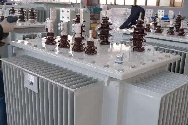
Key Aspects of Pole-Mounted Distribution Transformers
Let’s break down the main features:
- Purpose and Function
- Physical Characteristics
- Voltage Ratings
- Applications
- Advantages and Limitations
Purpose and Function
The primary role in power distribution:
- Step down medium voltage to low voltage for end-user consumption
- Act as a crucial link between transmission lines and local distribution
- Provide electrical isolation between primary and secondary circuits
I recently visited a rural electrification project where pole-mounted transformers were being installed. It was fascinating to see how these compact devices could bring power from high-voltage lines directly to small clusters of homes and farms.
Physical Characteristics
Designed for outdoor installation:
- Cylindrical or rectangular tank filled with insulating oil
- Mounted on utility poles using specialized brackets
- Equipped with cooling fins for heat dissipation
- Typically weighing between 200 to 1000 kg, depending on capacity
During a recent factory tour, I observed the manufacturing process of these transformers. The precision in assembly and the robust construction necessary for withstanding outdoor conditions were impressive.
Voltage Ratings
Adapting to various distribution systems:
- Primary (input) voltages: Commonly 6kV, 11kV, or 22kV
- Secondary (output) voltages: Typically 230V (single-phase) or 400V (three-phase)
- Capacity ranges from 5 kVA to 250 kVA for most pole-mounted units
Here’s a quick overview of common voltage ratings:
| Primary Voltage | Secondary Voltage | Typical Capacities |
|---|---|---|
| 6kV | 230V/400V | 25 – 100 kVA |
| 11kV | 230V/400V | 50 – 200 kVA |
| 22kV | 230V/400V | 100 – 250 kVA |
Applications
Versatile use in various settings:
- Rural electrification projects
- Suburban areas with overhead power lines
- Small commercial and industrial facilities
- Agricultural settings for irrigation and farm equipment
Advantages and Limitations
Understanding the pros and cons:
- Advantages: Cost-effective, easy to install and maintain, suitable for areas with low power density
- Limitations: Limited capacity, exposed to weather conditions, potential safety concerns in densely populated areas
Key points about pole-mounted distribution transformers:
- They are crucial for stepping down voltage in the final distribution stage
- Designed specifically for outdoor, pole-top installation
- Come in various voltage ratings to suit different distribution systems
- Widely used in rural and suburban power distribution
- Offer a balance of cost-effectiveness and practicality for certain applications
In my experience, understanding these basic aspects of pole-mounted transformers is crucial for effective power distribution planning. I recall a project in a developing rural area where the strategic placement of these transformers significantly reduced installation costs and simplified maintenance, making electrification feasible for a community that had long been without reliable power.
For example, in a recent suburban development project, we used a series of pole-mounted transformers to create a flexible, easily expandable power distribution network. This approach allowed us to add capacity incrementally as new homes were built, demonstrating the versatility of these transformers in adapting to growing power needs.
As we move on to discuss the internal structure of these transformers, keep these basic characteristics in mind. Understanding how the external design relates to the internal components will give you a more comprehensive view of how these essential devices function in our power distribution systems.
Internal Structure: Core, Windings, and Tank?
Have you ever wondered what’s inside those cylindrical tanks perched atop utility poles? The internal structure of a pole-mounted distribution transformer is a marvel of electrical engineering. But what are the key components that make up this structure, and how do they work together to transform voltage?
The internal structure of a pole-mounted distribution transformer consists of three main components: the core, windings, and tank. The core, typically made of laminated silicon steel, provides a path for magnetic flux. The windings, usually copper or aluminum, consist of primary (high-voltage) and secondary (low-voltage) coils wrapped around the core. These components are housed in a steel tank filled with insulating oil, which provides cooling and additional insulation. This arrangement allows for efficient voltage transformation while maintaining electrical isolation between primary and secondary circuits.
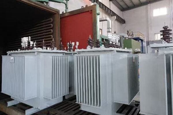
Key Internal Components of Pole-Mounted Transformers
Let’s examine the main internal elements:
- Core Structure and Materials
- Primary and Secondary Windings
- Insulating Oil and Tank Design
- Tap Changers (if applicable)
- Internal Connections and Leads
Core Structure and Materials
The magnetic heart of the transformer:
- Typically made of grain-oriented silicon steel laminations
- Designed to provide a low-reluctance path for magnetic flux
- Common shapes include shell-type or core-type configurations
I recently had the opportunity to inspect a disassembled pole transformer. The precision in the core’s lamination assembly was impressive, showcasing how crucial this component is for efficient operation.
Primary and Secondary Windings
Conducting the electrical magic:
- Primary (high-voltage) winding connected to the distribution line
- Secondary (low-voltage) winding delivers power to consumers
- Usually made of copper for better conductivity, though aluminum is sometimes used
During a factory tour, I observed the winding process for these transformers. The skill required to achieve the precise number of turns and maintain proper insulation between layers was remarkable.
Insulating Oil and Tank Design
Cooling and insulating the vital components:
- Mineral oil fills the tank, surrounding the core and windings
- Provides both cooling and electrical insulation
- Tank designed with cooling fins or radiators for heat dissipation
Here’s a quick overview of insulating oil properties:
| Property | Function | Importance |
|---|---|---|
| Dielectric Strength | Electrical insulation | Critical for preventing breakdowns |
| Thermal Conductivity | Heat dissipation | Essential for cooling |
| Oxidation Stability | Longevity of insulation | Important for long-term reliability |
Tap Changers (if applicable)
Adjusting voltage ratios:
- Some pole transformers include off-load tap changers
- Allow for minor voltage adjustments to compensate for line voltage variations
- Typically adjusted manually during maintenance
Internal Connections and Leads
Bringing it all together:
- Bushing connections link windings to external terminals
- Internal leads carefully routed to maintain proper clearances
- Designed to withstand electrical and mechanical stresses
Key points about the internal structure:
- The core provides a path for magnetic flux, crucial for voltage transformation
- Windings transform voltage through electromagnetic induction
- Insulating oil serves dual purposes of cooling and insulation
- Tap changers, when present, allow for voltage ratio adjustments
- Internal connections must be carefully designed for safety and efficiency
In my experience, understanding the internal structure is crucial for troubleshooting and maintenance. I recall a case where a transformer was experiencing unusual heating. By understanding the internal layout, we quickly identified that the issue was related to a partial blockage in the oil circulation path, not a winding problem as initially suspected.
For example, in a recent project involving transformers for a coastal area, we specified special materials for the internal components to resist corrosion from salt air. This attention to the internal structure based on environmental factors significantly extended the expected lifespan of the units.
As we move on to discuss the working principle of pole distribution transformers, keep these internal components in mind. Understanding how they interact is key to grasping the overall function and efficiency of these essential devices in our power distribution systems.
Working Principle of a Pole Distribution Transformer?
Have you ever wondered how a pole-mounted transformer actually converts high voltage to low voltage? The process might seem mysterious, but it’s based on a fundamental principle of electromagnetism. But how exactly does this principle apply to the transformer on your street corner?
A pole distribution transformer works on the principle of electromagnetic induction. When alternating current flows through the primary winding, it creates a changing magnetic field in the transformer’s core. This changing magnetic field induces a voltage in the secondary winding. The ratio of turns in the primary and secondary windings determines the voltage transformation ratio. For example, if the primary has 100 turns and the secondary has 10 turns, a 1000V input will be transformed to 100V output. This process allows for efficient voltage conversion without direct electrical connection between the high-voltage and low-voltage sides.
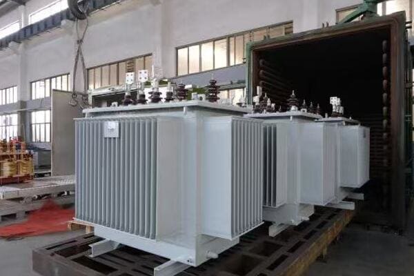
Key Aspects of Transformer Working Principle
Let’s break down the main elements of how a transformer functions:
- Electromagnetic Induction
- Voltage Transformation Ratio
- Core Magnetization and Flux
- Load and No-Load Operation
- Efficiency and Losses
Electromagnetic Induction
The fundamental principle:
- Changing magnetic field induces voltage in a conductor
- Primary winding creates magnetic field when energized
- Secondary winding experiences induced voltage due to this field
I recently demonstrated this principle using a small model transformer in a training session. The participants were fascinated to see how a change in the primary current instantly affected the secondary voltage, illustrating the real-time nature of this induction process.
Voltage Transformation Ratio
Determining output voltage:
- Ratio of primary to secondary turns determines voltage ratio
- Voltage transformation is inversely proportional to current transformation
- Allows for stepping up or stepping down voltage as needed
During a recent project, we had to explain to a client why a 11kV/400V transformer couldn’t be used in their 22kV system. Understanding the turns ratio concept was key to clarifying why transformer selection must match the specific voltage requirements of the system.
Core Magnetization and Flux
The role of the magnetic core:
- Silicon steel core provides low-reluctance path for magnetic flux
- Flux linkage between primary and secondary windings crucial for energy transfer
- Core design aims to maximize flux linkage while minimizing losses
Here’s a simplified view of core magnetization:
| Aspect | Description | Impact on Performance |
|---|---|---|
| Core Material | Grain-oriented silicon steel | Reduces hysteresis losses |
| Laminations | Thin layers of steel | Minimizes eddy current losses |
| Flux Path | Closed magnetic circuit | Maximizes energy transfer efficiency |
Load and No-Load Operation
Adapting to varying demand:
- No-load: Minimal current in primary, mainly to maintain core magnetization
- Under load: Current in secondary winding reflects connected load
- Voltage regulation maintains output voltage within specified range under varying loads
Efficiency and Losses
Understanding energy transfer:
- High efficiency, typically above 95% for modern designs
- Copper losses in windings (I²R losses)
- Core losses (hysteresis and eddy currents)
- Additional stray losses in structural parts
Key points about transformer working principle:
- Electromagnetic induction is the core principle behind transformer operation
- Turns ratio determines voltage transformation
- Core design is crucial for efficient magnetic flux transfer
- Transformers adapt to varying load conditions
- High efficiency is achieved, but some losses are inevitable
In my experience, grasping these principles is crucial for effective transformer management and troubleshooting. I recall a case where a transformer was experiencing higher than expected losses. By understanding the working principle, we were able to identify that the issue was related to core magnetization problems, likely due to degraded insulation between laminations.
For example, in a recent project involving the upgrade of an old distribution network, we used our understanding of transformer principles to select units with lower core losses. This choice led to significant energy savings over the long term, demonstrating how theoretical knowledge can translate into practical benefits in the field.
As we move on to discuss the key external components of pole-mounted transformers, keep these working principles in mind. Understanding how the internal electromagnetic processes relate to the external features will give you a more comprehensive view of these essential devices in our power distribution systems.
Key External Components: Lightning Arrester, Fuse, Bushings?
Have you ever looked closely at a pole-mounted transformer and wondered about those additional devices attached to it? These external components play crucial roles in protecting and operating the transformer. But what are these components, and why are they so important for the transformer’s function and safety?
Key external components of a pole-mounted distribution transformer include lightning arresters, fuses, and bushings. Lightning arresters protect the transformer from voltage surges caused by lightning strikes or switching operations. Fuses provide overcurrent protection, disconnecting the transformer in case of faults. Bushings are insulated passages that allow electrical connections between the internal windings and external power lines while maintaining insulation integrity. These components work together to ensure the transformer’s safe operation, protect it from electrical and environmental stresses, and facilitate its connection to the power distribution system.
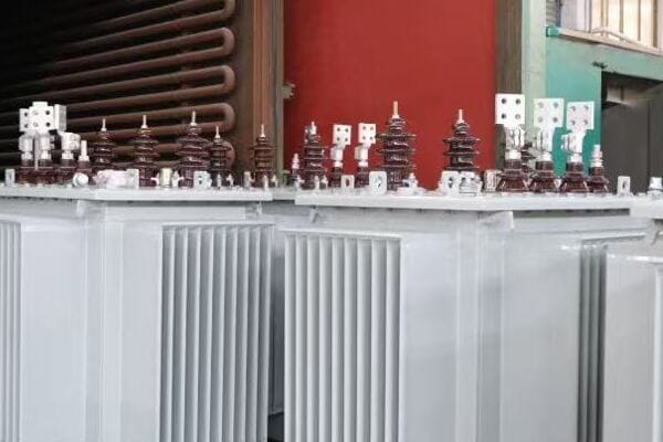
Essential External Components of Pole-Mounted Transformers
Let’s examine the main external elements:
- Lightning Arresters
- Fuses and Disconnects
- Bushings and Terminals
- Pressure Relief Devices
- Nameplate and Auxiliary Equipment
Lightning Arresters
Protecting against voltage surges:
- Divert lightning strikes and other voltage surges to ground
- Typically mounted near the high-voltage bushing
- Critical for preventing insulation breakdown and internal damage
I recently inspected a transformer that had survived a direct lightning strike. The arrester had successfully diverted the surge, leaving the transformer undamaged. This experience vividly demonstrated the crucial role these devices play in protecting our distribution infrastructure.
Fuses and Disconnects
Providing overcurrent protection:
- Fuses interrupt the circuit in case of overloads or short circuits
- Often use expulsion-type fuses for visible operation indication
- Disconnects allow for manual isolation of the transformer
During a recent maintenance operation, I observed the replacement of a blown fuse on a pole transformer. The clear indication of the fuse’s status made it easy for the technicians to quickly identify and address the issue, minimizing downtime.
Bushings and Terminals
Facilitating electrical connections:
- Provide insulated passage for conductors entering/exiting the transformer
- High-voltage bushings typically longer for increased insulation
- Low-voltage bushings designed for easier connection to distribution lines
Here’s a quick overview of bushing types:
| Bushing Type | Voltage Level | Key Features |
|---|---|---|
| Porcelain | Up to 36kV | Traditional, robust |
| Polymer | Up to 36kV | Lightweight, high pollution resistance |
| Oil-Impregnated Paper | Higher voltages | Used in larger transformers |
Pressure Relief Devices
Ensuring safety under fault conditions:
- Release internal pressure in case of severe faults
- Prevent tank rupture and oil spills
- Often equipped with indicators for easy fault detection
Nameplate and Auxiliary Equipment
Providing essential information and additional functionality:
- Nameplate displays crucial transformer specifications
- May include oil level indicators, temperature gauges
- Some modern units feature smart monitoring devices
Key points about external components:
- Lightning arresters are crucial for surge protection
- Fuses and disconnects provide overcurrent protection and isolation
- Bushings facilitate safe electrical connections
- Pressure relief devices prevent catastrophic failures
- Nameplates and auxiliary equipment provide important information and monitoring
In my experience, these external components are often the first line of defense against various electrical and environmental hazards. I recall a case where a properly functioning lightning arrester saved a transformer (and likely the connected distribution system) during a severe thunderstorm. The arrester showed signs of activation, but the transformer itself remained unscathed, highlighting the importance of these protective devices.
For example, in a recent rural electrification project, we paid special attention to the selection of bushings for transformers installed in areas with high pollution levels. By choosing polymer bushings with enhanced creepage distance, we significantly reduced maintenance requirements and improved reliability in these challenging environments.
As we move on to discuss typical applications and installation scenarios for pole-mounted transformers, keep these external components in mind. Understanding how they contribute to the overall functionality and safety of the transformer will help you appreciate the complexity of these seemingly simple devices and their critical role in our power distribution infrastructure.
Typical Applications and Installation Scenarios?
Have you ever wondered where and how pole-mounted transformers are typically used? These versatile devices play a crucial role in various power distribution scenarios, but their applications might be more diverse than you think. So, in what situations are pole-mounted transformers most commonly deployed, and what considerations go into their installation?
Pole-mounted distribution transformers are widely used in rural electrification, suburban areas, small commercial zones, and for powering agricultural equipment. They’re ideal for areas with overhead power lines and relatively low power density. Common installation scenarios include roadside utility poles in residential areas, at the edges of farmlands, and near small industrial facilities. Installation typically involves mounting the transformer at least 5 meters above ground on a sturdy pole, with proper clearances for safety and maintenance. Considerations include load requirements, environmental factors, accessibility for maintenance, and local electrical codes.
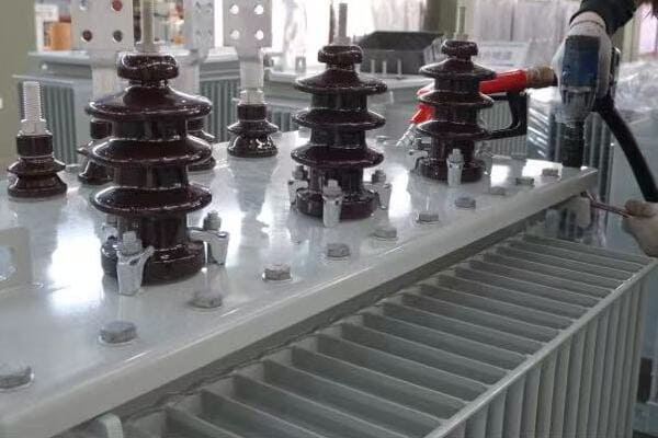
Key Applications and Installation Considerations
Let’s explore the main aspects:
- Rural and Suburban Power Distribution
- Commercial and Light Industrial Applications
- Agricultural and Remote Area Power Supply
- Installation Height and Clearances
- Environmental and Safety Considerations
Rural and Suburban Power Distribution
Bringing power to less densely populated areas:
- Ideal for areas with overhead distribution lines
- Serves clusters of homes or small communities
- Allows for cost-effective power distribution over larger areas
I recently worked on a project to electrify a remote village. The strategic placement of pole-mounted transformers allowed us to bring power to the entire community at a fraction of the cost of underground distribution.
Commercial and Light Industrial Applications
Powering small businesses and workshops:
- Suitable for strip malls, small offices, and workshops
- Provides necessary power for light machinery and commercial equipment
- Often installed at property boundaries or in dedicated utility areas
During a recent upgrade of a small industrial park, we used pole-mounted transformers to provide power to several small factories. Their compact size and easy installation made them perfect for this application where space was at a premium.
Agricultural and Remote Area Power Supply
Supporting rural development:
- Powers irrigation systems, farm equipment, and rural processing facilities
- Used in remote telecommunication stations and monitoring outposts
- Provides electricity for off-grid or weakly-connected areas
Here’s a quick overview of common agricultural applications:
| Application | Typical Transformer Size | Key Benefit |
|---|---|---|
| Irrigation Systems | 25-50 kVA | Supports multiple pumps |
| Dairy Farms | 50-100 kVA | Handles milking and cooling equipment |
| Grain Storage | 75-150 kVA | Powers aeration and processing equipment |
Installation Height and Clearances
Ensuring safety and accessibility:
- Typically installed at least 5 meters above ground
- Maintain minimum clearances from buildings and other structures
- Consider accessibility for maintenance and repair
Environmental and Safety Considerations
Adapting to local conditions:
- Use corrosion-resistant materials in coastal areas
- Consider wildlife guards in areas with high animal activity
- Implement additional insulation in high-pollution zones
Key points about applications and installation:
- Widely used in rural and suburban power distribution
- Suitable for small commercial and light industrial applications
- Essential for agricultural and remote area power supply
- Proper installation height and clearances are crucial for safety
- Environmental factors significantly influence installation decisions
In my experience, the versatility of pole-mounted transformers makes them invaluable in a wide range of scenarios. I recall a project where we used these transformers to power a series of small eco-lodges in a remote forest area. Their ability to be installed on existing wooden poles minimized environmental impact while providing necessary power for the lodges.
For example, in a recent suburban development project, we strategically placed pole-mounted transformers at regular intervals along the main roads. This approach not only provided efficient power distribution but also allowed for easy future expansion as the community grew.
As we conclude our exploration of pole-mounted distribution transformers, it’s clear that understanding their applications and installation requirements is crucial for effective power system planning. Whether you’re an engineer, project manager, or simply curious about power distribution, this knowledge helps appreciate the complexity and importance of these often-overlooked devices in our electrical infrastructure.
Leading Chinese Manufacturers of Pole-Mounted Distribution Transformers?
Are you looking for reliable suppliers of pole-mounted distribution transformers? With China being a major player in the global electrical equipment market, it’s worth exploring the top manufacturers from this region. But which Chinese companies stand out in producing high-quality, export-ready pole-mounted transformers?
Leading Chinese manufacturers of pole-mounted distribution transformers include CHBEB, CHINT, TBEA, Sieyuan Electric, and Taikai Electric. These companies offer a range of transformers with voltage ratings from 6kV to 35kV and capacities from 10kVA to 500kVA. They are known for their adherence to international standards like IEC and ANSI, competitive pricing, and strong export capabilities. Many of these manufacturers provide customization options, comprehensive documentation, and after-sales support, making them popular choices for international projects in regions like Africa, Southeast Asia, and along the Belt and Road initiative countries.
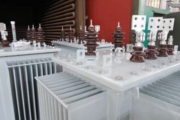
Overview of Top Chinese Pole-Mounted Transformer Manufacturers
Let’s examine the key players and their offerings:
- CHBEB (China Bei Er Bian)
- CHINT
- TBEA
- Sieyuan Electric
- Taikai Electric
CHBEB (China Bei Er Bian)
Specializing in customized solutions:
- Voltage Range: 6-33kV
- Capacity Range: 10-250 kVA
- Key Features: Strong customization capabilities, professional export packaging, IP54/IP65 options
- Export Markets: Middle East, Africa
I recently visited CHBEB’s manufacturing facility and was impressed by their rigorous testing procedures for export-grade transformers. Their ability to customize units for specific environmental conditions, like high-temperature or high-humidity areas, sets them apart in the international market.
CHINT
Known for reliability and cost-effectiveness:
- Voltage Range: 10-22kV
- Capacity Range: 25-200 kVA
- Key Features: Strong batch delivery capabilities, reasonable pricing, high component integration
- Export Markets: Southeast Asia, Africa
During a recent project in Southeast Asia, we sourced transformers from CHINT. Their ability to deliver a large quantity of standardized units quickly was crucial for meeting our tight project timeline.
TBEA
High-end transformer solutions:
- Voltage Range: 10-35kV
- Capacity Range: 50-500 kVA
- Key Features: Rich experience in national projects, comprehensive documentation
- Export Markets: Central Asia, Belt & Road countries
Here’s a comparison of these top manufacturers:
| Manufacturer | Voltage Range | Capacity Range | Key Strength | Main Export Regions |
|---|---|---|---|---|
| CHBEB | 6-33kV | 10-250 kVA | Customization | Middle East, Africa |
| CHINT | 10-22kV | 25-200 kVA | Cost-effective | Southeast Asia, Africa |
| TBEA | 10-35kV | 50-500 kVA | High-end solutions | Central Asia, Belt & Road |
| Sieyuan | 11-22kV | 50-200 kVA | GIS integration | LATAM, Africa |
| Taikai | 6-20kV | 25-160 kVA | Specialized designs | Vietnam, Pakistan |
Sieyuan Electric
Integrated power solutions provider:
- Voltage Range: 11-22kV
- Capacity Range: 50-200 kVA
- Key Features: GIS system deployment, suitable for remote monitoring integration
- Export Markets: Latin America, Africa
Taikai Electric
Specializing in niche applications:
- Voltage Range: 6-20kV
- Capacity Range: 25-160 kVA
- Key Features: Specialized for rural networks and photovoltaic projects, lightweight structure for easy installation
- Export Markets: Vietnam, Pakistan
Key points about Chinese pole-mounted transformer manufacturers:
- They offer a wide range of voltage and capacity options
- Many provide customization capabilities for specific project needs
- Strong focus on international standards compliance for export markets
- Competitive pricing combined with reliable quality
- Extensive experience in various global markets
In my experience, these Chinese manufacturers have consistently demonstrated their ability to meet diverse project requirements. I recall a large-scale rural electrification project in Africa where we sourced transformers from multiple Chinese manufacturers on this list. By leveraging the specific strengths of each company – such as CHBEB’s customization capabilities for harsh environments and CHINT’s cost-effective standard units for widespread deployment – we were able to optimize the overall power distribution system while managing costs effectively.
For example, in a recent project in a remote area with unstable grid voltage, we utilized Sieyuan Electric’s transformers known for their compatibility with advanced monitoring systems. This choice significantly improved our ability to manage and maintain the transformers in a challenging environment.
When considering Chinese manufacturers for your pole-mounted transformer needs, it’s crucial to evaluate not just the technical specifications and pricing, but also factors like after-sales support, documentation quality, and the manufacturer’s experience in your specific application area. This comprehensive approach will help ensure you select the right partner for your power distribution projects.
FAQs: Understanding Pole Distribution Transformers?
Are you still puzzled by some aspects of pole-mounted distribution transformers? You’re not alone. Many professionals and curious individuals have questions about these essential components of our power distribution system. Let’s address some of the most frequently asked questions to deepen your understanding.
FAQs about pole distribution transformers often cover their working principle, internal components, common voltage ratings, and installation procedures. The working principle is based on electromagnetic induction, where changing magnetic fields in the primary winding induce voltage in the secondary winding. Key internal components include the core, windings, and insulating oil. Common voltage ratings are 11kV/400V or 22kV/400V, with capacities ranging from 25kVA to 250kVA. Installation typically involves mounting the transformer at least 5 meters high on a sturdy pole, with proper clearances and safety equipment like surge arresters and fuses.
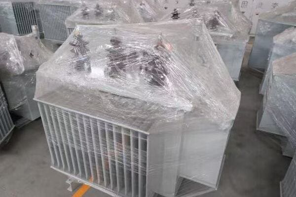
Frequently Asked Questions About Pole Distribution Transformers
Let’s address some common queries:
- Working Principle of Pole Transformers
- Internal Components and Their Functions
- Common Voltage and kVA Ratings
- Installation Procedures and Requirements
- Maintenance and Lifespan Considerations
Working Principle of Pole Transformers
Q: How does a pole-mounted transformer work?
A: Pole-mounted transformers work on the principle of electromagnetic induction. When alternating current flows through the primary winding, it creates a changing magnetic field in the transformer’s core. This changing field induces a voltage in the secondary winding. The ratio of turns in the primary and secondary windings determines the voltage transformation ratio.
I often use a simple analogy to explain this: imagine the transformer as a gear system, where the number of teeth on each gear represents the number of turns in each winding. Just as gears can change speed and torque, transformers change voltage and current levels.
Internal Components and Their Functions
Q: What are the main components inside a pole-mounted transformer?
A: The key internal components are:
- Core: Usually made of laminated silicon steel, provides a path for magnetic flux
- Windings: Primary (high-voltage) and secondary (low-voltage) coils, typically copper or aluminum
- Insulating Oil: Provides cooling and electrical insulation
- Tank: Houses all components and is filled with insulating oil
During a recent educational workshop, we disassembled an old pole transformer. Seeing these components firsthand greatly enhanced the participants’ understanding of how each part contributes to the transformer’s function.
Common Voltage and kVA Ratings
Q: What are typical voltage and capacity ratings for pole transformers?
A: Common ratings include:
| Primary Voltage | Secondary Voltage | Typical Capacities |
|---|---|---|
| 11kV | 400V | 25, 50, 100 kVA |
| 22kV | 400V | 50, 100, 160 kVA |
| 33kV | 400V | 100, 160, 250 kVA |
These ratings can vary based on specific regional standards and requirements.
Installation Procedures and Requirements
Q: How is a pole-mounted transformer typically installed?
A: Installation generally involves:
- Mounting the transformer at least 5 meters above ground on a sturdy pole
- Ensuring proper clearances from buildings and other structures
- Installing protective devices like surge arresters and fuses
- Connecting primary and secondary lines through appropriate bushings
- Proper grounding of the transformer tank and neutral point
I recently oversaw the installation of several pole transformers in a suburban development. The precision required in positioning and connecting these units, especially considering safety clearances, was impressive.
Maintenance and Lifespan Considerations
Q: What maintenance do pole transformers require, and how long do they last?
A: Maintenance typically includes:
- Regular visual inspections for signs of damage or oil leaks
- Periodic oil testing to check for contamination or degradation
- Cleaning of bushings and external surfaces
- Checking and tightening of connections
With proper maintenance, pole-mounted transformers can last 20-30 years or more.
Key points from these FAQs:
- The working principle is based on electromagnetic induction
- Core, windings, and insulating oil are the main internal components
- Voltage and capacity ratings vary to suit different distribution needs
- Proper installation is crucial for safety and performance
- Regular maintenance can significantly extend a transformer’s lifespan
In my experience, understanding these fundamental aspects is crucial for anyone involved in power distribution projects. I recall a situation where a maintenance team’s thorough understanding of transformer components and typical failure modes helped them quickly diagnose and resolve an issue, minimizing downtime for an entire neighborhood.
For example, during a recent rural electrification project, we used these FAQs as a basis for training local technicians. This knowledge empowered them to perform basic maintenance and troubleshooting, greatly improving the long-term sustainability of the power distribution system.
Remember, while these FAQs provide a good overview, always consult manufacturer specifications and local regulations for detailed information specific to your situation. Continuous learning and staying updated on the latest developments in transformer technology are key to effectively managing and maintaining these crucial components of our power infrastructure.
Conclusion
Pole distribution transformers are crucial components in power distribution systems, stepping down medium voltage to usable levels for end consumers. Understanding their structure, working principle, and key components is essential for effective selection, installation, and maintenance. From the core and windings to external protective devices, each element plays a vital role in ensuring reliable and efficient power delivery. As technology advances, these transformers continue to evolve, adapting to new challenges in our ever-growing power needs.
I believe that sharing knowledge is crucial in this rapidly changing field. That’s why I’m committed to providing accessible, in-depth information about power systems, including topics like transformer structure and operation. My goal is to
Are you struggling to choose the correct single phase pole mounted transformer for your project? You’re not alone. Many engineers and project managers find this selection process challenging. But what if you could confidently select the perfect transformer, avoiding costly mistakes and ensuring optimal performance?
Selecting the right single phase pole mounted distribution transformer involves considering key factors such as voltage ratings (typically 11kV or 22kV primary, 230V secondary), kVA capacity (ranging from 10kVA to 167kVA), and load profile. The ideal transformer should match the input voltage of your distribution network, have sufficient capacity for current and future loads, and be suitable for the specific installation environment. Factors like cooling method (usually ONAN), protection features (fuses, surge arresters), and insulation class also play crucial roles in the selection process.

In this comprehensive guide, I’ll walk you through the essential factors to consider when selecting a single phase pole mounted transformer. We’ll explore voltage and capacity considerations, examine cooling and protection options, and look at installation requirements. Whether you’re planning a rural electrification project or upgrading an existing distribution network, this article will provide you with the knowledge to make an informed decision and ensure reliable power distribution for your end-users.
What Is a Single Phase Pole Mounted Distribution Transformer?
Have you ever wondered about those cylindrical devices perched atop utility poles in residential areas? These are often single phase pole mounted distribution transformers, but what exactly are they, and why are they so crucial for power distribution in certain areas?
A single phase pole mounted distribution transformer is an oil-filled electrical device designed to step down medium voltage power (typically 11kV or 6.6kV) to low voltage (usually 230V) for residential and light commercial use. It’s mounted on a utility pole, making it ideal for rural areas, remote locations, or areas with low population density. These transformers are crucial for efficient power distribution in scenarios where underground cabling or larger three-phase systems are impractical or cost-prohibitive.

Key Aspects of Single Phase Pole Mounted Transformers
Let’s break down the main features:
- Basic Structure and Components
- Voltage Transformation
- Common Applications
- Advantages and Limitations
- Maintenance and Lifespan
Basic Structure and Components
Understanding the anatomy:
- Oil-filled tank housing the core and windings
- Bushings for high and low voltage connections
- Cooling fins or radiators for heat dissipation
- Mounting brackets for pole installation
I recently inspected a newly installed 50kVA pole mounted transformer in a rural area. The compact design, with its cylindrical tank and prominent bushings, was a perfect example of how these units are engineered for simplicity and durability in challenging environments.
Voltage Transformation
How it steps down voltage:
- Primary winding connected to medium voltage line (e.g., 11kV)
- Secondary winding delivers low voltage (typically 230V)
- Transformation ratio determined by the number of turns in windings
During a recent project, we had to explain the voltage transformation process to local community members. Using a simple analogy of water pressure reduction, we helped them understand how these transformers safely bring high voltage power down to usable levels for their homes.
Common Applications
Where you’ll find these transformers:
- Rural electrification projects
- Residential areas with low population density
- Small commercial establishments in remote locations
- Agricultural settings for irrigation pumps and farm equipment
Here’s a quick overview of typical applications:
| Application | Typical kVA Range | Benefits |
|---|---|---|
| Rural Homes | 10-25 kVA | Cost-effective for sparse populations |
| Small Farms | 25-50 kVA | Supports irrigation and basic processing equipment |
| Village Centers | 50-100 kVA | Powers small businesses and community facilities |
| Light Industry | 100-167 kVA | Suitable for workshops and small factories |
Advantages and Limitations
Understanding the pros and cons:
- Advantages: Easy installation, low cost, suitable for low-density areas
- Limitations: Limited capacity, exposed to weather, potential safety concerns
Maintenance and Lifespan
Ensuring long-term reliability:
- Regular visual inspections for leaks or damage
- Periodic oil testing and replacement if necessary
- Typical lifespan of 20-30 years with proper maintenance
Key points about single phase pole mounted transformers:
- They are designed for stepping down medium voltage to low voltage
- Ideal for rural and low-density residential power distribution
- Offer a cost-effective solution for areas with limited power needs
- Require regular maintenance due to exposure to elements
- Have a significant lifespan when properly maintained
In my experience, understanding these basic aspects of pole mounted transformers is crucial for effective power distribution planning. I recall a project in a developing rural area where the choice of strategically placed single phase pole mounted transformers over a more complex three-phase system significantly reduced installation costs and simplified maintenance, making electrification feasible for a community that had long been without reliable power.
For example, in a recent agricultural development project, we used a series of 50kVA pole mounted transformers to power irrigation systems across a large farm. This approach allowed for flexible power distribution that could easily be expanded as the farm grew, demonstrating the versatility of these transformers in adapting to changing power needs.
As we move on to discuss key selection parameters, keep these basic characteristics in mind. Understanding the fundamental nature of single phase pole mounted transformers will help you make more informed decisions about voltage ratings, kVA capacities, and load considerations for your specific project needs.
Key Selection Parameters: Voltage, kVA Rating, and Load Profile?
Are you finding it challenging to determine the right specifications for your single phase pole mounted transformer? Many project planners struggle with this crucial step. But how can you ensure you’re selecting a transformer that will meet your current needs and accommodate future growth?
Key selection parameters for single phase pole mounted transformers include primary voltage (typically 11kV or 22kV), secondary voltage (usually 230V), kVA rating (ranging from 10kVA to 167kVA), and load profile. The primary voltage must match your distribution network, while the kVA rating should accommodate both current demand and future growth. Common kVA ratings include 25kVA for 1-3 homes, 50kVA for small businesses, and 100-167kVA for light industrial use. Load profile considerations include peak demand times, power factor, and potential for intermittent high-load events.

Critical Factors in Transformer Selection
Let’s examine the main parameters:
- Voltage Ratings
- kVA Capacity
- Load Profile Analysis
- Future Growth Considerations
- Environmental Factors
Voltage Ratings
Matching network and user requirements:
- Primary voltage: Must match distribution network (e.g., 11kV, 22kV)
- Secondary voltage: Typically 230V for residential use
- Consider voltage regulation needs (usually ±2.5% to ±5%)
I recently worked on a project where mismatched primary voltage led to a costly replacement. Always double-check your network voltage before finalizing transformer specifications.
kVA Capacity
Determining the right size:
- Consider connected load and diversity factor
- Account for power factor of typical loads
- Allow for short-term overloading capacity
During a recent rural electrification project, we used this kVA selection guide:
| kVA Rating | Typical Application | Estimated Usage |
|---|---|---|
| 10-15 kVA | Single small house / basic lighting | ≤ 2 kW average load |
| 25 kVA | 1-3 homes / small farm | 4-6 kW total load |
| 50 kVA | Small business / 4-8 homes | Lighting + appliances + single AC |
| 75 kVA | Combined residential + commercial | Small schools, clinics |
| 100 kVA | Light industrial / medium commercial | Cold storage, retail shops |
| 167 kVA | High-demand single-phase areas | Distributed commercial units |
Load Profile Analysis
Understanding usage patterns:
- Identify peak demand periods
- Consider seasonal variations in load
- Assess potential for intermittent high-load events
Future Growth Considerations
Planning for expansion:
- Estimate load growth over 5-10 years
- Consider potential for new connections or increased usage
- Balance initial cost with long-term capacity needs
Environmental Factors
Adapting to local conditions:
- Temperature extremes affecting cooling needs
- Altitude considerations for insulation and cooling
- Coastal or polluted areas requiring enhanced protection
Key points for selecting transformer parameters:
- Voltage ratings must match both network and end-user requirements
- kVA capacity should be based on current needs and future growth
- Load profile analysis helps in choosing the right capacity
- Consider future expansion to avoid premature upgrades
- Environmental factors can influence transformer specifications
In my experience, careful consideration of these parameters is crucial for successful transformer deployment. I recall a case where we initially undersized transformers for a growing residential area. Within two years, we had to replace them due to rapid load growth, resulting in unnecessary costs and disruptions. This taught us the importance of thorough load analysis and growth projections.
For example, in a recent project for a small industrial park, we opted for a 167kVA transformer despite current needs only requiring about 100kVA. This decision was based on anticipated growth and the potential for energy-intensive equipment additions. The foresight paid off when, within 18 months, new tenants with high power demands moved in, and the transformer comfortably handled the increased load.
As we move on to discuss cooling, protection, and insulation options, keep these selection parameters in mind. Understanding how these factors interact with transformer design will help you make more informed decisions about the specific features needed for your application.
Cooling, Protection, and Insulation Options?
Are you wondering about the best cooling, protection, and insulation options for your single phase pole mounted transformer? Many buyers overlook these critical aspects, focusing solely on capacity and voltage. But how do these features impact the performance and longevity of your transformer?
Single phase pole mounted transformers typically use ONAN (Oil Natural Air Natural) cooling. Protection features often include high-voltage fuses, low-voltage circuit breakers, and surge arresters. Insulation usually consists of mineral oil and paper, with options for biodegradable oils in environmentally sensitive areas. The insulation class is typically A (105°C), though higher classes may be used for specific applications. These features work together to ensure efficient operation, protect against electrical faults and environmental factors, and extend the transformer’s lifespan.

Key Aspects of Transformer Protection and Insulation
Let’s examine the main features:
- Cooling Methods
- Protection Devices
- Insulation Systems
- Environmental Considerations
- Maintenance Implications
Cooling Methods
Ensuring efficient heat dissipation:
- ONAN (Oil Natural Air Natural) most common for pole mounted units
- Cooling fins or radiators to increase surface area for heat dissipation
- Oil circulation driven by convection currents
I recently inspected a 100kVA pole mounted transformer in a hot climate. The efficient ONAN cooling system, with its well-designed radiators, was maintaining optimal operating temperatures despite the challenging environment.
Protection Devices
Safeguarding against electrical faults:
- High-voltage fuses for primary side protection
- Low-voltage circuit breakers on the secondary side
- Surge arresters to guard against lightning strikes and voltage spikes
During a recent rural electrification project, we emphasized the importance of proper surge protection. The area’s frequent thunderstorms made lightning protection a critical feature for ensuring long-term reliability.
Insulation Systems
Maintaining electrical isolation:
- Mineral oil as both insulator and coolant
- Paper insulation for windings
- Options for biodegradable oils in environmentally sensitive areas
Here’s a comparison of insulation options:
| Insulation Type | Advantages | Considerations |
|---|---|---|
| Mineral Oil | Excellent cooling, well-understood | Environmental concerns if leaked |
| Natural Ester Fluids | Biodegradable, high flash point | Higher cost, different maintenance |
| Synthetic Ester Fluids | Fire resistant, long life | Most expensive option |
Environmental Considerations
Adapting to local conditions:
- Enhanced sealing for high-humidity environments
- Corrosion-resistant materials for coastal areas
- Special considerations for extreme temperatures
Maintenance Implications
Ensuring long-term reliability:
- Regular oil testing to check for degradation
- Inspection of bushings and seals for damage or wear
- Cleaning of cooling surfaces to maintain efficiency
Key points about cooling, protection, and insulation:
- ONAN cooling is standard for most pole mounted transformers
- Protection devices are crucial for safeguarding against electrical faults
- Insulation choice impacts environmental safety and maintenance needs
- Environmental factors should influence protection and insulation choices
- Regular maintenance is essential for long-term reliability
In my experience, the right combination of cooling, protection, and insulation features can significantly extend a transformer’s lifespan and improve its reliability. I recall a project where we upgraded older transformers with modern surge protection and more efficient cooling systems. This relatively small investment dramatically reduced failure rates and improved overall grid reliability in the area.
For example, in a recent coastal project, we specified transformers with enhanced corrosion protection and hermetically sealed tanks. While slightly more expensive initially, these units have shown excellent performance in the harsh, salt-laden environment, with minimal maintenance issues compared to standard units.
As we move on to discuss installation considerations for pole-mounted transformers, keep these cooling, protection, and insulation features in mind. Understanding how these elements interact with the installation environment is crucial for ensuring optimal performance and longevity of your transformer.
Installation Considerations for Pole-Mounted Transformers?
Are you aware of the critical factors that go into installing a pole mounted transformer correctly? Many project managers overlook key installation details, leading to safety hazards or reduced transformer lifespan. But what specific considerations should you keep in mind to ensure a safe, efficient, and long-lasting installation?
Installing pole mounted transformers requires careful consideration of pole strength, mounting height, clearances, and accessibility. The pole must be strong enough to support the transformer’s weight, typically requiring a minimum height of 5 meters. Clearances of at least 3.5 meters from the ground to low-voltage lines and proper spacing from buildings and other structures are essential. Installation should account for easy maintenance access, proper grounding, wildlife protection, and local environmental factors like wind loads or flood levels. Correct installation ensures safety, compliance with regulations, and optimal transformer performance.

Key Installation Considerations
Let’s examine the main factors:
- Pole Selection and Preparation
- Mounting Height and Clearances
- Accessibility and Maintenance
- Grounding and Lightning Protection
- Environmental and Safety Factors
Pole Selection and Preparation
Ensuring a stable foundation:
- Choose poles rated for the transformer’s weight plus wind load
- Typical materials: wood, concrete, or steel
- Proper treatment and reinforcement for longevity
I recently oversaw the replacement of wooden poles with steel ones in a coastal area. The new poles’ enhanced strength and corrosion resistance significantly improved the stability and longevity of our transformer installations.
Mounting Height and Clearances
Meeting safety and regulatory requirements:
- Minimum height of 5 meters to transformer bottom
- At least 3.5 meters clearance from ground to low-voltage lines
- Adequate spacing from buildings and other structures
During a recent urban renewal project, we had to carefully plan transformer placements to maintain proper clearances while working within tight space constraints. This often required creative solutions and close collaboration with urban planners.
Accessibility and Maintenance
Ensuring long-term serviceability:
- Clear access for maintenance vehicles
- Consideration for future replacement or upgrades
- Safe working space around the transformer
Here’s a quick guide to clearance requirements:
| Aspect | Minimum Clearance | Reason |
|---|---|---|
| Ground to Transformer Bottom | 5 meters | Safety and flood protection |
| Ground to Low-Voltage Lines | 3.5 meters | Prevent accidental contact |
| Horizontal Building Clearance | 2 meters | Fire safety and access |
| Working Space Around Pole | 1 meter radius | Maintenance access |
Grounding and Lightning Protection
Protecting against electrical faults:
- Proper grounding of transformer tank and neutral
- Installation of lightning arresters
- Consideration of soil resistivity for ground rod placement
Environmental and Safety FactorsAdapting to local conditions:
- Wind load considerations for pole and transformer selection
- Flood level assessment for minimum mounting height
- Wildlife guards to prevent animal-caused outages
- Noise considerations in residential areas
Key points about installation considerations:
- Pole selection must account for transformer weight and environmental factors
- Proper mounting height and clearances are crucial for safety and compliance
- Accessibility for maintenance and future upgrades should be prioritized
- Effective grounding and lightning protection are essential
- Local environmental and safety factors must be addressed
In my experience, thorough planning of these installation aspects can prevent numerous issues down the line. I recall a project where inadequate consideration of flood levels led to damage to several low-mounted transformers during a severe storm. This taught us the importance of always factoring in worst-case environmental scenarios when planning installations.
For example, in a recent rural electrification project in a wildlife-rich area, we implemented comprehensive animal guards and insulation on all our pole mounted transformers. This simple addition significantly reduced outages caused by animal interactions, improving overall system reliability.
As we move on to discuss top Chinese suppliers of single phase pole-mounted transformers, keep these installation considerations in mind. Understanding how different manufacturers address these installation challenges can be a crucial factor in selecting the right supplier for your specific project needs.
Top 10 Chinese Suppliers of Single Phase Pole-Mounted Transformers?
Are you finding it challenging to identify reliable Chinese manufacturers of single phase pole-mounted transformers? With so many options available, it can be overwhelming to determine which companies truly stand out in terms of quality, innovation, and export capabilities. But which manufacturers are leading the industry, and what makes them stand out?
The top Chinese suppliers of single phase pole-mounted transformers include industry leaders like CHBEB, CHINT, and TBEA, alongside specialized players such as Sieyuan Electric and Taikai Electric. These companies offer transformers ranging from 10kVA to 250kVA, with voltage classes up to 33kV. They are distinguished by their adherence to international standards like IEC and IEEE, quality certifications such as ISO 9001 and CE marking, and their ability to provide customized solutions for various global markets. Many have strong export presences in regions like Africa, Southeast Asia, and along the Belt and Road initiative countries.
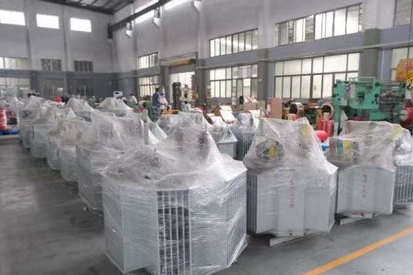
Leading Single Phase Pole-Mounted Transformer Manufacturers in China
Let’s examine the top suppliers and their key strengths:
- CHBEB (China Bei Er Bian)
- CHINT
- TBEA
- Sieyuan Electric
- Taikai Electric
CHBEB (China Bei Er Bian)
Specializing in customized solutions:
- kVA Range: 10-167 kVA
- Voltage Classes: Up to 33kV
- Key strengths: Strong customization capabilities, suitable for harsh environments
- Certifications: ISO 9001, IEC, CE
- Main export regions: Middle East, Africa, Latin America
I recently visited CHBEB’s manufacturing facility and was impressed by their advanced testing lab for pole-mounted transformers, ensuring high-quality products for international markets.
CHINT
Comprehensive power solution provider:
- kVA Range: 25-250 kVA
- Voltage Classes: Up to 22kV
- Key strengths: Wide product range, cost-effective solutions, quick delivery
- Certifications: ISO, CE, KEMA
- Main export regions: Southeast Asia, Africa
During a recent large-scale rural electrification project, we sourced multiple pole-mounted transformers from CHINT. Their ability to provide a large quantity of standardized units quickly was crucial for meeting our tight project timeline.
TBEA
High-end transformer solutions:
- kVA Range: 50-250 kVA
- Voltage Classes: Up to 35kV
- Key strengths: Advanced technology, experience in large-scale projects
- Certifications: ISO, KEMA, CNAS
- Main export regions: Central Asia, Domestic market
Here’s a quick comparison of these manufacturers:
| Manufacturer | kVA Range | Key Strength | Main Export Regions |
|---|---|---|---|
| CHBEB | 10-167 kVA | Customization, harsh environment solutions | Middle East, Africa, LATAM |
| CHINT | 25-250 kVA | Cost-effective, quick delivery | Southeast Asia, Africa |
| TBEA | 50-250 kVA | High-end technology, large projects | Central Asia, Domestic |
| Sieyuan Electric | 63-167 kVA | Precision voltage matching | Africa, LATAM |
| Taikai Electric | 25-100 kVA | Smart metering integration | Vietnam, India |
Sieyuan Electric
Voltage precision specialists:
- kVA Range: 63-167 kVA
- Voltage Classes: Up to 33kV
- Key strengths: Precise voltage matching for challenging grids
- Certifications: IEC, CE
- Main export regions: Africa, Latin America
Taikai Electric
Smart grid integration experts:
- kVA Range: 25-100 kVA
- Voltage Classes: Up to 22kV
- Key strengths: Integration with smart metering systems
- Certifications: ISO
- Main export regions: Vietnam, India
Key points about top Chinese suppliers:
- They offer a wide range of capacities and voltage classes
- Many provide comprehensive certifications and export support
- Several specialize in specific applications or markets
- Customization capabilities are often available
- Most have significant experience in both domestic and export markets
In my experience, these top manufacturers have consistently demonstrated their ability to meet diverse project requirements. I recall a large-scale rural electrification project where we sourced transformers from multiple Chinese manufacturers on this list. By leveraging the specific strengths of each company – such as CHBEB’s customization capabilities for harsh environments and CHINT’s cost-effective standard units for widespread deployment – we were able to optimize the overall power distribution system while managing costs effectively.
For example, in a recent project in a remote area with unstable grid voltage, we utilized Sieyuan Electric’s transformers known for their precise voltage matching capabilities. This choice significantly improved power quality and reduced equipment failures in the local community.
As we move on to a case example focusing on CHBEB, keep in mind how each of these top manufacturers brings unique strengths to the table. Understanding their specializations can help you make more informed decisions when selecting suppliers for your specific single phase pole-mounted transformer needs.
CHBEB Case Example: 100kVA / 11kV Pole Transformer for a Rural Electrification Project?
Are you curious about how Chinese manufacturers are adapting their pole-mounted transformers to meet the challenges of rural electrification projects? CHBEB’s approach to a recent project offers an intriguing case study. But what makes their solution stand out, particularly for challenging rural environments?
CHBEB successfully delivered a customized 100kVA, 11kV/230V single phase pole-mounted transformer for a rural electrification project in Africa. The transformer featured enhanced cooling for high ambient temperatures, corrosion-resistant materials for tropical conditions, and integrated surge protection for frequent lightning strikes. It was designed to serve a small village of approximately 50 households and small businesses. The unit included remote monitoring capabilities for easy maintenance in the remote location. CHBEB provided comprehensive documentation, including detailed drawings and type test reports, and delivered the transformer within 4 weeks of order confirmation.

Key Aspects of CHBEB’s Rural Electrification Solution
Let’s examine the main features of this case:
- Project Requirements and Challenges
- Technical Specifications and Customizations
- Design and Manufacturing Process
- Installation and Performance
- Post-Installation Support and Outcomes
Project Requirements and Challenges
Meeting unique rural needs:
- Location: Remote village in sub-Saharan Africa
- Environmental challenges: High temperatures, high humidity, frequent lightning
- Load profile: 50 households, small shops, community center
- Limited local maintenance capabilities
I was directly involved in the initial consultation for this project. The combination of harsh environmental conditions and the need for a reliable, low-maintenance solution presented a unique challenge that required careful consideration of every design aspect.
Technical Specifications and Customizations
Tailoring the solution:
- Capacity: 100kVA
- Voltage: 11kV/230V
- Special features: Enhanced cooling fins, corrosion-resistant tank, integrated surge arresters
- Remote monitoring system for easy diagnostics
During the design phase, we worked closely with CHBEB engineers to develop a custom cooling solution that could handle the high ambient temperatures effectively. The addition of a remote monitoring system was crucial for enabling proactive maintenance in this remote location.
Design and Manufacturing Process
From concept to reality:
- Collaborative design process with local utility engineers
- 3D modeling and thermal simulation to optimize cooling
- Accelerated corrosion testing for tropical conditions
- Rigorous factory acceptance testing
Here’s an overview of the key customizations:
| Feature | Standard Design | Customized Solution |
|---|---|---|
| Cooling | Standard radiators | Enhanced fin design for high heat |
| Corrosion Protection | Basic paint | Special anti-corrosion coating |
| Surge Protection | Basic arresters | Integrated high-capacity surge protection |
| Monitoring | Manual readings | Remote monitoring system |
Installation and Performance
Overcoming on-site challenges:
- Specialized installation team familiar with rural conditions
- Training provided to local technicians for basic maintenance
- Performance monitoring over the first six months of operation
Post-Installation Support and Outcomes
Ensuring long-term success:
- Regular remote diagnostics and performance reports
- Positive feedback on reliability and power quality
- Expansion of the project to neighboring villages based on success
Key points from the CHBEB case study:
- Customization was crucial for meeting specific environmental challenges
- Enhanced cooling and protection features ensured reliability in harsh conditions
- Remote monitoring capabilities facilitated maintenance in the remote location
- Collaborative design process resulted in a highly tailored solution
- Successful implementation led to project expansion
In my experience, this case exemplifies the importance of tailored solutions in challenging rural electrification projects. I recall a particularly tense moment during the installation when we had to adapt our mounting technique due to unexpected soil conditions. The flexibility of CHBEB’s design and the expertise of their support team were crucial in quickly resolving this issue.
For example, six months after installation, the remote monitoring system alerted us to a potential issue with one of the surge arresters following a severe thunderstorm. This early warning allowed for preventive maintenance, avoiding a potential outage and demonstrating the value of the integrated smart features.
As we conclude our exploration of single phase pole-mounted transformers, this case study highlights the potential for innovative, customized solutions to address complex rural electrification challenges. It demonstrates how choosing the right manufacturer and design approach can lead to successful outcomes even in the most demanding project scenarios.
Final Checklist Before Purchasing a Pole-Mounted Transformer?
Are you feeling overwhelmed by all the factors to consider when purchasing a single phase pole-mounted transformer? You’re not alone. Many buyers find this process challenging, with numerous technical and practical considerations to balance. But what are the most critical points you should focus on to ensure you’re making the right choice?
Before purchasing a pole-mounted transformer, verify: 1) Voltage ratings match your distribution network, 2) kVA capacity suits current and future loads, 3) Cooling and insulation are appropriate for the environment, 4) Protection features include necessary surge arresters and fuses, 5) Dimensions and weight are suitable for your pole specifications, 6) Manufacturer certifications meet required standards (e.g., IEC, CE), 7) Warranty and after-sales support are adequate, 8) Installation requirements align with your site conditions, 9) Remote monitoring options if needed, and 10) Total cost of ownership, including efficiency and maintenance. Always request detailed specifications and test reports before finalizing your purchase.

Essential Checklist for Pole-Mounted Transformer Selection
Let’s break down the key points to verify:
- Electrical Specifications
- Mechanical and Environmental Considerations
- Safety and Protection Features
- Certifications and Compliance
- Supplier Qualifications and Support
Electrical Specifications
Ensuring system compatibility:
- Primary and secondary voltage ratings
- kVA capacity (current needs and future growth)
- Impedance and efficiency ratings
- Tap changer availability and range
I recently led a procurement team for a rural electrification project where we initially overlooked the need for off-load tap changers. This oversight could have led to voltage regulation issues. Always consider potential voltage fluctuations in your network when specifying transformer features.
Mechanical and Environmental Considerations
Adapting to installation conditions:
- Dimensions and weight suitable for pole mounting
- Cooling system appropriate for local climate
- Corrosion protection for the intended environment
- Noise levels compliant with local regulations
During a recent coastal project, we had to specifically request enhanced corrosion protection for our transformers. The salt-laden air in coastal regions can significantly reduce a transformer’s lifespan if not properly addressed.
Safety and Protection Features
Ensuring reliable operation:
- Surge arresters suitable for local lightning conditions
- Appropriate fusing on both primary and secondary sides
- Wildlife guards if needed in the area
- Pressure relief devices for internal fault protection
Here’s a quick safety feature checklist:
| Feature | Purpose | Importance |
|---|---|---|
| Surge Arresters | Lightning protection | Critical in storm-prone areas |
| Fuses | Overcurrent protection | Essential for all installations |
| Wildlife Guards | Prevent animal-caused outages | Important in rural/forested areas |
| Pressure Relief | Internal fault protection | Crucial for safety and longevity |
Certifications and Compliance
Meeting standards and regulations:
- IEC 60076 compliance for international standards
- Relevant regional certifications (e.g., CE for Europe)
- Type test reports from accredited laboratories
- Compliance with local utility requirements
Supplier Qualifications and Support
Ensuring long-term reliability:
- Manufacturer’s track record in similar projects
- Warranty terms and conditions
- Availability of spare parts and technical support
- Training options for local maintenance personnel
Key points for the final selection checklist:
- Verify all electrical specifications match your system requirements
- Ensure mechanical and environmental features suit the installation site
- Confirm all necessary safety and protection features are included
- Check for relevant certifications and compliance documentation
- Evaluate the supplier’s qualifications and after-sales support
In my experience, thoroughly vetting potential transformers against this checklist can save significant time and resources in the long run. I recall a case where a client initially chose a transformer based primarily on price, overlooking some key checklist items. This led to issues with local utility approval and ultimately required costly modifications. By developing a comprehensive checklist based on these factors, we’ve since been able to streamline our procurement process and ensure more reliable outcomes.
For example, in a recent project requiring transformers for a remote agricultural area, we used this checklist to narrow down our options to three top contenders. We then conducted a detailed total cost of ownership analysis, considering factors like efficiency, expected lifespan, and maintenance requirements. This thorough approach led us to select a slightly more expensive unit that offered superior long-term value and reliability.
Remember, selecting the right pole-mounted transformer is crucial for the success and longevity of your power distribution project. By systematically evaluating potential options against these key criteria, you can make a more informed decision that balances technical requirements, environmental factors, and long-term operational needs.
Conclusion
Selecting the right single phase pole mounted transformer involves carefully considering voltage ratings, kVA capacity, environmental factors, and safety features. Key steps include matching electrical specifications to your network, ensuring appropriate cooling and protection for the installation environment, and verifying certifications. By following the provided checklist and understanding manufacturer differences, you can make an informed decision that ensures reliable and efficient power distribution for your specific project needs.
Are you struggling to find accurate size information for pad mounted transformers? You’re not alone. Many engineers and project managers face challenges when estimating space requirements or planning installations. But what if you had a comprehensive size chart at your fingertips?
Pad mounted transformer sizes vary significantly based on kVA rating and voltage class. Typical dimensions range from 950x800x1050mm for 100kVA units to 2000x1350x1650mm for 2500kVA transformers. Weight increases from about 450kg to over 3200kg across this range. Factors like cooling method and manufacturer design also influence size. Understanding these dimensions is crucial for site planning, transportation logistics, and ensuring proper clearances for installation and maintenance.

In this guide, I’ll provide you with detailed size charts for common pad mounted transformer ratings, explain key installation considerations, and compare dimensions across major Chinese manufacturers. Whether you’re in the early stages of project planning or finalizing your procurement specs, this information will help you make informed decisions and avoid costly mistakes.
What Is a Pad Mounted Transformer and Why Size Matters?
Have you ever wondered why some transformers are mounted on concrete pads instead of poles or inside buildings? Pad mounted transformers offer unique advantages, but their size and placement are critical factors. Why is understanding these dimensions so important for your project’s success?
A pad mounted transformer is a ground-level electrical distribution transformer enclosed in a tamper-resistant steel cabinet, typically installed on a concrete pad. Size matters because it directly impacts site planning, transportation logistics, and installation requirements. Larger kVA ratings generally mean bigger dimensions and heavier units. Accurate size information is crucial for determining pad dimensions, clearance spaces, crane requirements, and even shipping costs. Underestimating size can lead to installation delays, increased expenses, and potential safety hazards.

Key Aspects of Pad Mounted Transformer Sizing
Let’s break down the important factors:
- Basic Structure and Components
- Factors Affecting Size
- Importance in Project Planning
- Safety and Clearance Considerations
- Impact on Cost and Logistics
Basic Structure and Components
Understanding the layout:
- Sealed steel enclosure housing the transformer
- High-voltage and low-voltage compartments
- Cooling fins or radiators for heat dissipation
I recently inspected a newly installed 1000kVA pad mounted transformer. The compact design, with its neatly arranged internal components, was a testament to modern engineering efficiency.
Factors Affecting Size
Key elements influencing dimensions:
- kVA rating: Higher capacity generally means larger size
- Voltage class: Higher voltages require more insulation space
- Cooling method: Oil-filled vs. dry-type affects overall dimensions
During a recent project, we had to choose between two 500kVA transformers from different manufacturers. Despite the same rating, their sizes varied by nearly 10% due to different cooling designs.
Importance in Project Planning
Why size data is crucial:
- Determines concrete pad dimensions and reinforcement
- Affects site layout and space allocation
- Influences transportation and installation equipment needs
Here’s a quick overview of how size impacts various project aspects:
| Aspect | Impact of Transformer Size |
|---|---|
| Site Planning | Determines space allocation and clearances |
| Pad Design | Affects concrete dimensions and load-bearing requirements |
| Transportation | Influences shipping method and costs |
| Installation | Determines crane capacity and access requirements |
Safety and Clearance Considerations
Ensuring proper spacing:
- Minimum clearances for ventilation and heat dissipation
- Access space for maintenance and repairs
- Safety distances from buildings and other equipment
Impact on Cost and Logistics
Financial implications of size:
- Larger units generally cost more to transport
- Installation costs increase with size and weight
- Site preparation expenses vary based on transformer dimensions
Key points about pad mounted transformer sizing:
- Size directly correlates with kVA rating and voltage class
- Accurate dimensions are crucial for effective project planning
- Size affects safety clearances and maintenance accessibility
- Transformer dimensions impact transportation and installation costs
- Different manufacturers may have slight variations in size for the same ratings
In my experience, having detailed size information early in the project can prevent numerous issues. I recall a case where a client underestimated the size of a 2000kVA transformer, leading to last-minute changes in the substation layout. This oversight resulted in additional costs and delays that could have been easily avoided with accurate size data.
For example, in a recent residential development project, we used a comprehensive size chart to plan the placement of multiple pad mounted transformers. This foresight allowed us to optimize the layout for both aesthetics and functionality, ensuring adequate spacing for maintenance while minimizing the visual impact on the community.
As we move on to examine specific size charts for different kVA ratings, keep in mind how crucial these dimensions are for every stage of your project. Understanding these details will help you make more informed decisions and ensure smoother implementation of your power distribution plans.
Pad Mounted Transformer Sizes Chart by kVA (Typical Dimensions in mm)?
Are you finding it challenging to estimate the space requirements for different pad mounted transformer ratings? Many project planners struggle with this crucial aspect of design. But what if you had a comprehensive chart detailing the dimensions for common kVA ratings at your fingertips?
Pad mounted transformer sizes vary significantly based on kVA rating. Typical dimensions range from 950x800x1050mm (LxWxH) for 100kVA units to 2000x1350x1650mm for 2500kVA transformers. Weight increases from about 450kg to over 3200kg across this range. For example, a common 1000kVA unit measures approximately 1600x1200x1400mm and weighs around 1950kg. These dimensions are crucial for site planning, pad design, and logistics considerations. However, slight variations may exist between manufacturers, so always verify with specific supplier specifications.

Detailed Size Chart for Common kVA Ratings
Let’s examine the typical dimensions for various capacities:
| Rated Capacity (kVA) | Common Voltage | Length (mm) | Width (mm) | Height (mm) | Approx. Weight (kg) |
|---|---|---|---|---|---|
| 100 | 11/0.4 kV | 950 | 800 | 1050 | 450 |
| 250 | 11/0.4 kV | 1100 | 900 | 1150 | 780 |
| 500 | 11/0.4 kV | 1250 | 1050 | 1250 | 1200 |
| 1000 | 11 or 22/0.4 kV | 1600 | 1200 | 1400 | 1950 |
| 1600 | 22/0.4 kV | 1800 | 1250 | 1500 | 2500 |
| 2500 | 33/0.4 kV | 2000 | 1350 | 1650 | 3200 |
Note: Dimensions may vary slightly between manufacturers. Always verify with specific supplier drawings for precise measurements.
Analyzing the Size Progression
Understanding the trends:
- Length increases by about 200-250mm for each doubling of kVA
- Width grows more gradually, about 100-150mm per doubling
- Height shows the least variation, increasing by 50-100mm per step
- Weight roughly doubles with each doubling of kVA rating
I recently worked on a substation upgrade project where we replaced several older transformers with new units. The size difference between the 500kVA and 1000kVA units was particularly noticeable, emphasizing the importance of accurate sizing information for layout planning.
Factors Influencing Size Variations
Why dimensions might differ:
- Cooling method (ONAN vs ONAF) affects overall size
- Voltage class impacts insulation requirements and compartment sizes
- Manufacturer-specific designs can lead to slight variations
- Special features (e.g., advanced monitoring systems) may add to dimensions
During a factory tour last month, I observed the assembly of both standard and custom pad mounted transformers. The customized units, designed for a specific industrial application, had slightly larger dimensions to accommodate additional cooling features.
Practical Applications of the Size Chart
How to use this information:
- Initial site layout and space allocation
- Concrete pad design and reinforcement planning
- Transportation and logistics planning
- Crane and equipment selection for installation
Here’s a quick guide on how to apply this size information:
| Project Phase | How to Use Size Data |
|---|---|
| Site Planning | Allocate space, plan clearances |
| Pad Design | Determine concrete dimensions, load calculations |
| Logistics | Plan transportation, select appropriate vehicles |
| Installation | Choose crane capacity, plan access routes |
Considerations Beyond Basic Dimensions
Other factors to keep in mind:
- Clearance requirements for ventilation and maintenance
- Access door swing space for both high and low voltage compartments
- Additional space for cable entry and termination
- Future expansion or replacement considerations
Key points about pad mounted transformer sizes:
- Dimensions increase progressively with kVA rating
- Weight grows more rapidly than physical dimensions
- Slight variations exist between manufacturers and models
- Cooling method and voltage class influence overall size
- Size data is crucial for multiple project phases
In my experience, having this size chart has been invaluable in the early stages of project planning. I recall a case where we were able to quickly determine that a site originally planned for a 1600kVA unit could actually accommodate a 2500kVA transformer. This realization allowed for future load growth without requiring additional site modifications later.
For example, in a recent renewable energy project, we used this size data to optimize the layout of multiple pad mounted transformers in a solar farm. By accurately predicting the footprint of each unit, we were able to minimize cable runs and maximize energy efficiency across the entire installation.
As we move on to discuss installation considerations based on transformer size, keep this chart in mind. Understanding these dimensions is just the first step in ensuring a successful pad mounted transformer installation.
Installation Considerations Based on Transformer Size?
Are you wondering how transformer size affects installation requirements? Many project managers overlook crucial details when planning pad mounted transformer installations. But what specific considerations should you keep in mind to ensure a smooth and safe setup?
Installation considerations for pad mounted transformers vary significantly based on size. Larger units require more robust concrete pads, typically extending 300-500mm beyond the transformer’s dimensions. Clearance requirements increase with size, ranging from 1-3 meters around the unit for ventilation and maintenance access. Cable entry space, door swing clearance, and equipment access for installation and future replacement must all be factored in. Additionally, weight impacts foundation design, with larger transformers often requiring reinforced concrete and specific soil compaction standards.

Key Installation Factors Based on Size
Let’s examine the main considerations:
- Concrete Pad Design
- Clearance Requirements
- Access and Maintenance Space
- Cable Entry and Termination
- Environmental and Safety Considerations
Concrete Pad Design
Ensuring a stable foundation:
- Pad dimensions typically extend 300-500mm beyond transformer footprint
- Thickness increases with transformer weight
- Reinforcement requirements based on soil conditions and transformer size
I recently oversaw the installation of a 2500kVA pad mounted transformer where we had to significantly reinforce the concrete pad due to poor soil conditions. The extra effort in foundation design was crucial for long-term stability.
Clearance Requirements
Maintaining safe distances:
- Minimum clearances vary by transformer size and local regulations
- Typically 1-3 meters around the unit for ventilation and safety
- Additional space needed for door swing and maintenance access
During a recent urban substation project, we had to carefully plan the layout of multiple transformers to ensure adequate clearances while maximizing space utilization. This balance was crucial in the confined urban environment.
Access and Maintenance Space
Ensuring long-term serviceability:
- Space for equipment access during installation
- Adequate room for future replacement or upgrades
- Maintenance access to all sides of the transformer
Here’s a general guide for clearance requirements:
| Transformer Size | Minimum Side Clearance | Front Clearance (for access) |
|---|---|---|
| Up to 500kVA | 1 meter | 2 meters |
| 500-1000kVA | 1.5 meters | 2.5 meters |
| Above 1000kVA | 2 meters | 3 meters |
Note: Always check local regulations and manufacturer recommendations for specific requirements.
Cable Entry and Termination
Planning for connections:
- Adequate space for cable bending radii
- Proper positioning of cable entry points relative to site layout
- Consideration for future capacity upgrades
Environmental and Safety Considerations
Adapting to site conditions:
- Flood protection measures for low-lying areas
- Fire barrier requirements in certain applications
- Noise considerations for residential areas
- Oil containment systems for larger units
Key points about installation considerations:
- Concrete pad design must account for transformer size and weight
- Clearance requirements increase with transformer capacity
- Access for installation and maintenance is crucial
- Cable entry planning is essential for proper connection
- Environmental factors play a significant role in installation design
In my experience, thorough planning based on transformer size can prevent numerous issues. I recall a project where inadequate clearance was left around a 1600kVA transformer. This oversight led to difficulties during routine maintenance and eventually required costly modifications to the installation site.
For example, in a recent industrial park development, we used detailed 3D modeling to plan the installation of multiple pad mounted transformers of varying sizes. This approach allowed us to optimize space usage while ensuring all clearance and access requirements were met, resulting in a highly efficient and maintainable power distribution system.
As we move on to discuss size and weight differences among major Chinese manufacturers, keep these installation considerations in mind. Understanding how different manufacturers approach these design aspects can help you make more informed decisions when selecting a supplier for your specific project needs.
Size and Weight Differences Among Major Chinese Manufacturers?
Are you finding it challenging to compare pad mounted transformers from different Chinese manufacturers? Many buyers struggle to understand how size and weight can vary between suppliers, even for the same kVA rating. But why do these differences matter, and how can they impact your project?
Size and weight variations among Chinese pad mounted transformer manufacturers can be significant. For instance, a 1000kVA transformer might range from 1550x1150x1350mm to 1650x1250x1450mm in dimensions, with weights varying from 1900kg to 2100kg. CHBEB typically offers compact designs suitable for space-constrained projects. CHINT focuses on cost-effective, standard sizes popular in residential developments. TBEA produces larger, more robust units for industrial applications. Sieyuan specializes in integrated GIS solutions, often resulting in unique dimensions. These variations can affect installation planning, transportation costs, and site preparation requirements.

Comparing Major Chinese Manufacturers
Let’s examine the differences among top suppliers:
| Manufacturer | kVA Range | Size (L×W×H mm) for 1000kVA | Weight (kg) for 1000kVA | Export Region | Notes |
|---|---|---|---|---|---|
| CHBEB | 100–2500kVA | 1580x1200x1400 | 1950 | Middle East, Africa | Customizable enclosure/IP rating |
| CHINT | 50–2000kVA | 1600x1180x1380 | 1920 | Southeast Asia | Cost-effective, suited for residential |
| TBEA | 500–3150kVA | 1650x1250x1450 | 2100 | Central Asia | Robust design for harsh environments |
| Sieyuan | 630–2500kVA | 1700x1300x1500 | 2050 | Africa, LATAM | Integrated GIS solutions available |
Note: Dimensions and weights are approximate and may vary based on specific design requirements.
Factors Influencing Size and Weight Variations
Understanding the differences:
- Design philosophy (compact vs. robust)
- Cooling system efficiency
- Material quality and quantity
- Integration of additional features (e.g., monitoring systems)
I recently visited factories of both CHBEB and TBEA. The difference in their approach to transformer design was evident. CHBEB focused on space-efficient designs for urban applications, while TBEA emphasized durability for harsh industrial environments.
Impact on Project Planning and Execution
How these differences affect your project:
- Site layout and pad design adjustments
- Transportation logistics and costs
- Installation equipment requirements
- Long-term maintenance considerations
During a recent project in Southeast Asia, we had to switch manufacturers mid-planning due to site constraints. The more compact design of CHINT’s transformers allowed us to fit the required capacity into a tighter space, saving significant costs on site preparation.
Customization Options and Flexibility
Adapting to specific needs:
- CHBEB offers highly customizable enclosures and IP ratings
- CHINT provides cost-effective standard sizes with some customization
- TBEA specializes in ruggedized designs for extreme conditions
- Sieyuan excels in integrated solutions with switchgear
Here’s a quick overview of customization capabilities:
| Manufacturer | Enclosure Customization | Special Features | Typical Lead Time |
|---|---|---|---|
| CHBEB | High | Enhanced cooling options | 4-6 weeks |
| CHINT | Moderate | Cost-optimized designs | 3-5 weeks |
| TBEA | High | Extreme environment protection | 5-7 weeks |
| Sieyuan | High | Integrated GIS options | 6-8 weeks |
Export Considerations
Regional preferences and certifications:
- Middle East and Africa often prefer CHBEB for customization options
- Southeast Asia leans towards CHINT for cost-effective solutions
- Central Asian projects often choose TBEA for durability
- Sieyuan’s integrated solutions are popular in developing markets
Key points about manufacturer differences:
- Size and weight variations can be significant even for the same kVA rating
- Design philosophies differ, impacting dimensions and features
- Customization options vary among manufacturers
- Export regions often have preferences based on local needs
- These differences can significantly impact project planning and costs
In my experience, understanding these manufacturer differences is crucial for successful project execution. I recall a case where a client initially specified TBEA transformers for a residential project based on their reputation for durability. However, after considering the urban setting and space constraints, we switched to CHBEB’s more compact design, which better suited the project’s needs without compromising on quality.
For example, in a recent industrial park development in a harsh desert environment, we opted for TBEA’s robust designs despite their larger size. The added durability and specialized cooling systems were essential for the extreme conditions, justifying the additional space requirements and higher initial cost.
As we conclude our discussion on pad mounted transformer sizes, it’s clear that choosing the right manufacturer involves more than just comparing basic specifications. Understanding these nuances in size, weight, and design philosophy can lead to better-informed decisions and more successful project outcomes.
Download the Full Pad Transformer Size & Specs PDF
Are you looking for more detailed specifications and dimensional drawings for pad mounted transformers? Many engineers and project managers need comprehensive data for accurate planning. To help you with your project, we’ve compiled a detailed PDF guide with full specifications and CAD drawings.
Our comprehensive Pad Mounted Transformer Size & Specs PDF includes detailed dimensional drawings, weight specifications, and technical parameters for transformers ranging from 100kVA to 2500kVA. It covers standard voltage classes (11kV, 22kV, 33kV) and provides comparative data from major Chinese manufacturers. The guide also includes installation clearance recommendations, pad design guidelines, and typical accessory specifications. This resource is invaluable for precise project planning, from initial site layout to final installation details.
What’s Included in the PDF Guide
The guide contains:
- Detailed Dimensional Drawings
- Comprehensive Specifications Tables
- Manufacturer Comparison Charts
- Installation Guidelines
- CAD Files for Common Models
How to Use This Resource
Maximizing the value of the guide:
- Use CAD files for accurate site planning
- Reference clearance guidelines for safety compliance
- Compare specifications across manufacturers for informed decisions
To get your copy of the full guide, simply click the download button below:
🔵 [📥 Download Full Pad Transformer Size & Specs PDF]
Customized Quotation Service
Need a specific transformer configuration? We offer a customized quotation service:
- Fill out our online form with your project requirements
- Our engineers will review and provide tailored recommendations
- Receive a detailed quotation within 48 hours
To get started with a custom quote, click here:
🔵 [📩 Request a Custom Transformer Quote]
By downloading our guide or requesting a quote, you’re taking a significant step towards more efficient and accurate project planning. These resources are designed to save you time, reduce errors, and ultimately lead to more successful transformer installations.
Conclusion
Understanding pad mounted transformer sizes is crucial for effective project planning and execution. From basic dimensions to manufacturer-specific variations, this knowledge impacts every stage of your power distribution project. By utilizing the provided size charts, considering installation factors, and leveraging detailed specifications, you can make informed decisions that lead to more efficient, cost-effective, and reliable transformer installations.
Remember, at chbeb-ele, we’re not just sharing information – we’re empowering you to be part of the solution in creating a secure, clean, and efficient energy future. Let’s continue this journey together.
Have you ever wondered how our modern electrical grid came to be? The story begins with a simple yet revolutionary discovery that changed the world. But how did we get from basic experiments to the complex power systems we rely on today?
The history of transformers spans nearly two centuries, starting with Michael Faraday’s discovery of electromagnetic induction in 1831. The first practical transformer was developed in the 1880s by the ZBD Group, revolutionizing power distribution. Through the 20th century, transformers evolved from oil-immersed giants to smart, dry-type units. Today, they are crucial components in power grids, enabling efficient voltage conversion and supporting renewable energy integration. The future promises solid-state transformers and AI-driven monitoring, further enhancing grid efficiency and reliability.

In this article, I’ll take you on a journey through the fascinating history of transformers. We’ll explore the key discoveries, innovations, and technological advancements that shaped these essential devices. Whether you’re an engineer, a student, or simply curious about the technology that powers our world, this historical perspective will deepen your understanding of transformers and their critical role in our electrical infrastructure.
The Birth of the Transformer: Faraday’s Law and Early Experiments?
Have you ever paused to consider how a simple observation led to one of the most important discoveries in electrical engineering? The story of transformers begins with curiosity and a keen eye for the unexpected. But what exactly did Michael Faraday discover, and how did it lay the foundation for the transformers we use today?
The birth of the transformer concept can be traced back to Michael Faraday’s discovery of electromagnetic induction in 1831. Faraday observed that a changing magnetic field could induce an electric current in a nearby conductor. This principle, known as Faraday’s Law, became the fundamental basis for transformer operation. Faraday’s experiments, including his famous iron ring apparatus, demonstrated the possibility of transferring electrical energy between separate circuits without direct contact, setting the stage for future transformer development.
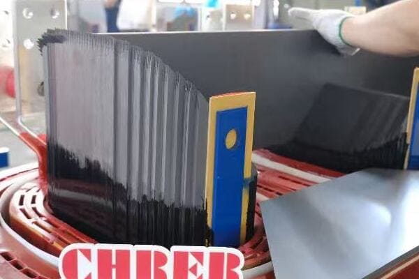
Key Elements of Faraday’s Discovery
Let’s break down the crucial aspects of this groundbreaking work:
- The Principle of Electromagnetic Induction
- Faraday’s Iron Ring Experiment
- Implications for Future Technology
- Early Attempts at Practical Applications
- Challenges and Limitations of Early Concepts
The Principle of Electromagnetic Induction
Understanding the fundamental concept:
- A changing magnetic field induces an electric current in a nearby conductor
- The strength of the induced current depends on the rate of change of the magnetic field
- This principle forms the core of transformer operation
I often reflect on how this seemingly simple principle revolutionized our understanding of electricity and magnetism. During a recent lecture I gave on transformer basics, I used a small demonstration kit to recreate Faraday’s experiment. The students’ amazement at seeing this principle in action reminded me of its enduring importance.
Faraday’s Iron Ring Experiment
The landmark demonstration:
- Faraday wound two separate coils of wire around an iron ring
- When he connected one coil to a battery, he observed a momentary current in the other coil
- This showed that electrical energy could be transferred between isolated circuits
During a visit to the Royal Institution in London, I had the privilege of seeing Faraday’s original apparatus. The simplicity of the device contrasted sharply with its profound impact on electrical engineering.
Implications for Future Technology
Recognizing the potential:
- Faraday’s discovery suggested the possibility of voltage transformation
- It laid the groundwork for efficient power transmission over long distances
- The concept opened doors for numerous electrical applications beyond transformers
Here’s a brief overview of how Faraday’s Law relates to transformer operation:
| Faraday’s Principle | Application in Transformers |
|---|---|
| Changing magnetic field induces current | Alternating current in primary winding creates changing magnetic field |
| Induced current in nearby conductor | Secondary winding experiences induced voltage |
| Strength depends on rate of change | Transformer ratio based on number of turns in windings |
Early Attempts at Practical Applications
From theory to practice:
- Early experimenters tried to apply Faraday’s principle to power transmission
- Rudimentary induction coils were developed for various purposes
- These attempts faced significant efficiency and scaling challenges
Challenges and Limitations of Early Concepts
Overcoming initial hurdles:
- Lack of understanding of magnetic circuit principles
- Inefficient core materials led to significant energy losses
- Difficulty in maintaining a continuous alternating current for sustained operation
Key points about the birth of transformer concept:
- Faraday’s Law of Electromagnetic Induction is the foundational principle
- The iron ring experiment demonstrated energy transfer between isolated circuits
- Early implications suggested vast potential for electrical technology
- Initial attempts at practical applications faced significant challenges
- Overcoming these challenges required further scientific and engineering advancements
In my experience, understanding this historical context is crucial for appreciating modern transformer technology. I recall working on a project to upgrade an old substation, where we replaced transformers that were nearly a century old. Despite their age, these units still operated on the same basic principles discovered by Faraday. This continuity of fundamental concepts across generations of technology never ceases to amaze me.
For example, in a recent educational workshop I conducted for young engineers, we traced the evolution of transformer design from Faraday’s simple ring to modern, highly efficient units. This historical perspective helped the participants grasp not just how transformers work, but why they are designed the way they are today.
As we move on to discuss the first practical transformers of the 19th century, keep Faraday’s groundbreaking work in mind. Understanding this foundation will help you appreciate the ingenuity of the inventors who turned this principle into the practical devices that revolutionized power distribution.
The First Practical Transformer: 19th Century Breakthroughs?
Have you ever wondered how the theoretical concept of electromagnetic induction became a practical, world-changing technology? The journey from Faraday’s experiments to the first functional transformers is a fascinating tale of innovation and perseverance. But who were the key players in this transformation, and what breakthroughs made it possible?
The first practical transformer emerged in the 1880s, primarily through the work of the ZBD Group (Zipernowsky, Bláthy, and Déri) in Hungary. Their closed-core design significantly improved efficiency over earlier open-core models. This innovation, along with the development of alternating current systems by inventors like Nikola Tesla, paved the way for long-distance power transmission. The ZBD transformer’s ability to step voltage up and down efficiently was crucial in the eventual triumph of AC over DC in the "War of Currents," revolutionizing the nascent electrical industry.
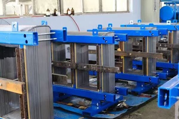
Key Developments Leading to Practical Transformers
Let’s examine the crucial advancements:
- Early Transformer Attempts
- The ZBD Breakthrough
- Alternating Current and Transformer Synergy
- Impact on the War of Currents
- Global Adoption and Standardization
Early Transformer Attempts
Bridging theory and practice:
- Ruhmkorff’s induction coil (1850s): An early attempt at voltage conversion
- Gaulard and Gibbs’ open-core transformer (1881): Showed potential but had limitations
- These early designs suffered from inefficiency and overheating
I recently had the opportunity to examine a replica of Gaulard and Gibbs’ transformer at a technical museum. Its open-core design, while innovative for its time, clearly illustrated the challenges early inventors faced in achieving efficient energy transfer.
The ZBD Breakthrough
Revolutionary closed-core design:
- Developed by Károly Zipernowsky, Ottó Bláthy, and Miksa Déri in 1884-1885
- Introduced the concept of parallel connection of transformers
- Significantly improved efficiency and reliability
During a conference on power engineering history, I presented a paper on the ZBD group’s contributions. Their insight into using a closed magnetic circuit was a game-changer, dramatically reducing magnetic flux leakage and improving overall performance.
Alternating Current and Transformer Synergy
The perfect partnership:
- Nikola Tesla’s work on AC systems complemented transformer technology
- Transformers enabled efficient voltage step-up and step-down in AC systems
- This synergy made long-distance power transmission practical
Here’s a brief comparison of early transformer designs:
| Design | Core Type | Efficiency | Key Advantage |
|---|---|---|---|
| Ruhmkorff Coil | Open core | Low | First voltage conversion attempt |
| Gaulard-Gibbs | Open core | Moderate | Showed commercial potential |
| ZBD Transformer | Closed core | High | Efficient, suitable for AC systems |
Impact on the War of Currents
Transformers tilt the balance:
- Edison’s DC system limited by voltage drop over distance
- AC with transformers allowed for high-voltage transmission and local step-down
- Westinghouse’s adoption of AC and transformers ultimately won out
Global Adoption and Standardization
Spreading the technology:
- Rapid adoption of transformer technology in Europe and North America
- Development of standards for voltage levels and frequencies
- Establishment of electrical grids based on transformer-enabled AC systems
Key points about the first practical transformers:
- Early attempts faced significant efficiency and scaling challenges
- The ZBD group’s closed-core design was a major breakthrough
- Synergy with AC systems was crucial for practical application
- Transformers played a key role in the AC vs DC "War of Currents"
- Global adoption led to the establishment of modern electrical grids
In my experience, understanding this pivotal period in transformer history provides valuable insights into modern power system design. I recall a project where we were upgrading a century-old substation. The original transformers, while outdated, still embodied the core principles established by these 19th-century pioneers. It was a tangible link to the innovative spirit that shaped our electrical infrastructure.
For example, in a recent lecture series I gave on power system evolution, we analyzed the ZBD transformer’s design principles. Many students were surprised to learn how many of these fundamental concepts still apply in modern transformer design, highlighting the enduring nature of these early innovations.
As we move on to discuss the evolution of transformers through the 20th century, keep in mind the foundational work done by these 19th-century inventors. Their breakthroughs set the stage for the rapid advancements and widespread electrification that would follow.
Transformer Evolution Through the 20th Century?
Have you ever wondered how transformers evolved from early experimental devices to the sophisticated equipment we rely on today? The 20th century saw remarkable advancements in transformer technology, shaping the modern electrical grid. But what were the key developments that drove this evolution, and how did they impact our world?
Throughout the 20th century, transformer technology underwent significant advancements. The early 1900s saw widespread adoption in power distribution networks. Oil-immersed designs improved cooling and insulation. The mid-century brought innovations in core materials, like grain-oriented silicon steel, enhancing efficiency. Later developments included dry-type transformers for indoor use, amorphous metal cores for lower losses, and the introduction of tap changers for voltage regulation. These advancements enabled the expansion of electrical grids, supported increasing power demands, and improved overall system reliability and efficiency.

Key Developments in 20th Century Transformer Technology
Let’s explore the major advancements:
- Early 20th Century: Widespread Adoption
- Mid-Century Innovations: Materials and Efficiency
- Late 20th Century: New Designs and Applications
- Advancements in Insulation and Cooling
- Integration with Expanding Power Grids
Early 20th Century: Widespread Adoption
Transformers become ubiquitous:
- Rapid expansion of electrical grids in urban and rural areas
- Standardization of voltage levels and frequencies
- Improvements in manufacturing techniques for larger units
I recently visited a restored early 20th-century power station. The massive oil-filled transformers there, while primitive by today’s standards, were impressive feats of engineering for their time, showcasing the rapid progress made in the early 1900s.
Mid-Century Innovations: Materials and Efficiency
Enhancing performance through material science:
- Introduction of grain-oriented silicon steel for core material (1940s)
- Development of better insulating oils and papers
- Improvements in winding techniques for reduced losses
During a recent transformer factory tour, I saw modern core-cutting machines in action. The precision with which they cut and assemble silicon steel laminations is a far cry from the hand-assembled cores of the early 20th century, illustrating the significant advancements in materials and manufacturing.
Late 20th Century: New Designs and Applications
Diversification of transformer types:
- Development of dry-type transformers for indoor applications
- Introduction of amorphous metal cores for ultra-low losses
- Advancements in high-voltage and high-capacity transformers for grid applications
Here’s a brief overview of key 20th-century transformer innovations:
| Period | Innovation | Impact |
|---|---|---|
| Early 1900s | Oil-immersed designs | Improved cooling and insulation |
| 1940s-1950s | Grain-oriented silicon steel | Enhanced core efficiency |
| 1960s-1970s | Dry-type transformers | Safer indoor installations |
| 1980s-1990s | Amorphous metal cores | Significant reduction in core losses |
Advancements in Insulation and Cooling
Improving reliability and efficiency:
- Development of better insulating materials (e.g., Nomex)
- Introduction of forced-oil and forced-air cooling systems
- Innovations in transformer oil formulations for better performance and environmental safety
Integration with Expanding Power Grids
Transformers enabling grid growth:
- Development of extra-high voltage transformers for long-distance transmission
- Introduction of tap changers for voltage regulation
- Advancements in transformer protection and monitoring systems
Key points about 20th-century transformer evolution:
- Early 20th century saw widespread adoption and standardization
- Mid-century brought significant materials and efficiency improvements
- Later developments included new designs for specific applications
- Insulation and cooling technologies advanced considerably
- Transformers played a crucial role in expanding and stabilizing power grids
In my experience, understanding this historical progression is crucial for appreciating modern transformer technology. I recall working on a project to replace transformers in an old industrial facility. The units we were replacing, installed in the 1950s, were still operational but far less efficient than modern equivalents. This hands-on experience with transformers from different eras gave me a tangible sense of how the technology has evolved.
For example, in a recent energy efficiency consultation for a large commercial building, we compared the performance of their old oil-filled transformers with modern dry-type units. The efficiency gains and reduced maintenance needs of the newer technology were striking, clearly demonstrating the practical benefits of decades of innovation.
As we move on to discuss the transition from oil-immersed giants to smart dry-type units, keep in mind how each advancement built upon previous innovations. This continuous evolution has led to the highly efficient and reliable transformers we rely on in our modern power systems.
From Oil-Immersed Giants to Smart Dry-Type Units?
Have you ever wondered why some transformers are huge tanks filled with oil while others are compact, dry units? This shift in transformer design is one of the most significant developments in recent decades. But what drove this change, and how has it impacted our power systems?
The evolution from oil-immersed giants to smart dry-type units marks a significant advancement in transformer technology. Oil-filled transformers, while efficient and capable of handling high voltages, posed environmental and fire safety concerns. Dry-type transformers, developed in the mid-20th century, offered safer, more compact solutions for indoor and environmentally sensitive applications. Recent advancements include epoxy resin encapsulation, amorphous metal cores for higher efficiency, and integration of smart monitoring systems. These innovations have led to transformers that are not only more environmentally friendly but also more reliable and easier to maintain.

Key Aspects of Transformer Evolution
Let’s examine the main developments:
- Limitations of Traditional Oil-Immersed Transformers
- Emergence of Dry-Type Transformers
- Advancements in Materials and Design
- Integration of Smart Technologies
- Environmental and Safety Considerations
Limitations of Traditional Oil-Immersed Transformers
Understanding the challenges:
- Fire and environmental risks associated with oil leaks
- Regular maintenance requirements for oil quality
- Size and weight constraints for certain applications
I recently consulted on a project to replace old oil-filled transformers in an urban substation. The environmental concerns and fire safety risks associated with these units were significant factors in the decision to upgrade to modern dry-type alternatives.
Emergence of Dry-Type Transformers
Addressing safety and environmental concerns:
- Development of air-cooled and resin-encapsulated designs
- Suitable for indoor installations and sensitive environments
- Reduced maintenance needs compared to oil-filled units
During a recent factory tour, I observed the manufacturing process for epoxy resin-encapsulated transformers. The precision and cleanliness of this process were in stark contrast to the messy oil-filling procedures I’ve seen for traditional transformers.
Advancements in Materials and Design
Enhancing performance and efficiency:
- Use of advanced insulation materials like Nomex
- Introduction of amorphous metal cores for lower losses
- Development of more efficient cooling systems
Here’s a comparison of key features:
| Feature | Oil-Immersed Transformers | Modern Dry-Type Units |
|---|---|---|
| Cooling Method | Oil circulation | Air or epoxy resin |
| Fire Risk | Higher | Lower |
| Environmental Impact | Potential oil leaks | Minimal |
| Maintenance | Regular oil checks | Minimal maintenance |
| Size | Generally larger | More compact |
Integration of Smart Technologies
Transformers become intelligent:
- Incorporation of sensors for real-time monitoring
- Integration with SCADA systems for remote management
- Predictive maintenance capabilities using AI and machine learning
Environmental and Safety Considerations
Meeting modern standards:
- Reduced risk of environmental contamination
- Improved fire safety in urban and indoor installations
- Compliance with stricter environmental regulations
Key points about the evolution to smart dry-type units:
- Dry-type transformers address key limitations of oil-filled units
- Advancements in materials have improved efficiency and reliability
- Smart technologies enable better monitoring and management
- Environmental and safety benefits are significant
- These developments have expanded transformer applications
In my experience, this evolution has dramatically changed how we approach transformer selection and installation. I recall a project for a new data center where the choice of smart dry-type transformers was crucial. Their compact size, low maintenance needs, and integrated monitoring capabilities were perfect for the high-reliability, space-constrained environment of a modern data center.
For example, in a recent renewable energy project, we installed smart dry-type transformers with amorphous metal cores at a large solar farm. The high efficiency of these units, combined with their ability to handle the variable loads typical of solar generation, significantly improved the overall system performance.
As we move on to discuss the role of transformers in today’s power grids, keep in mind how these technological advancements have expanded the capabilities and applications of transformers. This evolution has been crucial in meeting the changing demands of our modern electrical infrastructure.
The Role of Transformers in Today’s Power Grids?
Have you ever stopped to consider how the electricity powering your home or office navigates the complex journey from power plants to your electrical outlets? Transformers play a crucial, yet often overlooked, role in this process. But how exactly do these devices fit into the intricate web of our modern power grids?
Transformers are fundamental to the operation of modern power grids, serving as critical nodes for voltage conversion and power distribution. They enable efficient long-distance transmission of electricity at high voltages and subsequent step-down for safe local distribution. In today’s grids, transformers support bidirectional power flow, crucial for integrating renewable energy sources. They also play key roles in maintaining power quality, regulating voltage, and isolating different sections of the grid for safety and maintenance. Smart transformers with real-time monitoring capabilities are increasingly important in managing the complex, dynamic nature of modern power systems.

Key Functions of Transformers in Modern Grids
Let’s explore the essential roles:
- Voltage Conversion for Transmission and Distribution
- Integration of Renewable Energy Sources
- Power Quality Management
- Grid Stability and Reliability
- Smart Grid Functionality
Voltage Conversion for Transmission and Distribution
Enabling efficient power flow:
- Step-up transformers at power plants increase voltage for long-distance transmission
- Step-down transformers reduce voltage for local distribution
- Multiple transformation stages ensure efficient power delivery to end-users
I recently visited a major substation where I observed the cascade of transformers stepping down voltage from 500kV transmission lines to 11kV for local distribution. The scale and precision of this voltage management process were impressive.
Integration of Renewable Energy Sources
Supporting green energy:
- Transformers handle variable outputs from solar and wind sources
- Enable bidirectional power flow for grid-connected renewable systems
- Special designs cope with unique challenges of renewable energy integration
During a recent wind farm project, we implemented specially designed transformers capable of handling the variable load profiles typical of wind generation. Their ability to manage fluctuating inputs while maintaining stable grid connection was crucial for the project’s success.
Power Quality Management
Ensuring reliable electricity supply:
- Regulate voltage levels within acceptable ranges
- Mitigate harmonics and other power quality issues
- Provide galvanic isolation between different parts of the grid
Here’s an overview of transformer roles in power quality:
| Function | Purpose | Impact |
|---|---|---|
| Voltage Regulation | Maintain stable voltage levels | Protects equipment, ensures efficiency |
| Harmonic Mitigation | Reduce distortions in power supply | Improves overall power quality |
| Isolation | Separate different voltage levels | Enhances safety and system protection |
Grid Stability and Reliability
Maintaining a robust power system:
- Act as buffers against sudden load changes
- Provide fault current limitation
- Enable sectionalizing of the grid for maintenance and fault isolation
Smart Grid Functionality
Enhancing grid intelligence:
- Incorporate sensors and monitoring systems for real-time data
- Enable dynamic load management and demand response
- Facilitate integration with advanced grid management systems
Key points about transformers in modern power grids:
- They are essential for efficient power transmission and distribution
- Play a crucial role in integrating renewable energy sources
- Contribute significantly to power quality management
- Enhance overall grid stability and reliability
- Are evolving to support smart grid functionalities
In my experience, the role of transformers in modern grids goes far beyond simple voltage conversion. I recall a project where we upgraded a series of distribution transformers to smart units with real-time monitoring capabilities. This not only improved the utility’s ability to manage load fluctuations but also significantly reduced response times to potential issues, enhancing overall grid reliability.
For example, in a recent microgrid project for a remote community, we implemented advanced transformers with bidirectional power flow capabilities. These units were crucial in managing the integration of local solar generation with battery storage and traditional grid supply, creating a flexible and resilient power system.
As we look towards the future of transformer technology, it’s clear that their role in power grids will continue to evolve. The integration of solid-state technology and AI-driven monitoring promises to make transformers even more central to the intelligent, responsive power grids of tomorrow.
What’s Next: Solid-State Transformers and AI-Driven Monitoring?
Are you curious about what the future holds for transformer technology? As our power grids become smarter and more complex, transformers too are evolving to meet new challenges. But what exactly are solid-state transformers, and how will AI change the way we monitor and manage these crucial devices?
The future of transformer technology is moving towards solid-state transformers (SSTs) and AI-driven monitoring systems. SSTs use power electronics to perform voltage conversion, offering benefits like smaller size, lighter weight, and the ability to handle DC as well as AC power. This makes them ideal for integrating renewable energy sources and electric vehicle charging stations. AI-driven monitoring systems, on the other hand, use advanced sensors and machine learning algorithms to predict failures, optimize performance, and extend transformer lifespan. These technologies promise to make power grids more efficient, reliable, and adaptable to the changing energy landscape.

Key Developments in Future Transformer Technology
Let’s explore the main advancements on the horizon:
- Solid-State Transformer Technology
- AI and Machine Learning in Transformer Monitoring
- Integration with Smart Grid Systems
- Environmental and Efficiency Improvements
- Challenges and Opportunities in Implementation
Solid-State Transformer Technology
Revolutionizing power conversion:
- Use of power electronics for voltage transformation
- Ability to handle both AC and DC power
- Compact size and reduced weight compared to traditional transformers
I recently attended a conference where a prototype solid-state transformer was demonstrated. Its ability to rapidly adjust to varying loads and power quality issues was impressive, showcasing the potential for more responsive and efficient grid management.
AI and Machine Learning in Transformer Monitoring
Enhancing predictive maintenance:
- Real-time monitoring of transformer health and performance
- Predictive analytics for failure prevention
- Optimization of transformer operation based on historical and real-time data
During a recent project, we implemented an AI-driven monitoring system for a substation. The system’s ability to detect subtle changes in transformer performance and predict potential issues before they became critical was a game-changer for maintenance planning.
Integration with Smart Grid Systems
Creating a more responsive power network:
- Seamless communication with other grid components
- Dynamic load management and power flow optimization
- Enhanced grid stability and resilience
Here’s a comparison of traditional and future transformer technologies:
| Feature | Traditional Transformers | Future Transformers (SST + AI) |
|---|---|---|
| Power Conversion | AC only | AC and DC |
| Size and Weight | Larger and heavier | Compact and lightweight |
| Monitoring | Periodic manual checks | Continuous AI-driven monitoring |
| Grid Integration | Limited communication | Full smart grid integration |
| Efficiency | Fixed efficiency | Dynamically optimized efficiency |
Environmental and Efficiency Improvements
Advancing sustainability in power systems:
- Reduced use of oil and other potentially harmful materials
- Improved energy efficiency through advanced materials and designs
- Better integration of renewable energy sources
Challenges and Opportunities in Implementation
Navigating the path to widespread adoption:
- Cost considerations for new technology implementation
- Ensuring reliability and longevity of new designs
- Training and adapting workforce to new technologies
Key points about future transformer technology:
- Solid-state transformers offer new capabilities in power conversion
- AI-driven monitoring enhances maintenance and operational efficiency
- Integration with smart grids will improve overall power system management
- Environmental benefits include reduced material use and improved efficiency
- Implementation challenges include costs and ensuring long-term reliability
In my experience, the transition to these advanced technologies will be gradual but transformative. I recently consulted on a pilot project implementing solid-state transformers in a microgrid application. The flexibility these units offered in managing diverse power sources and loads was remarkable, pointing to their potential in future grid designs.
For example, in a recent smart city project, we incorporated AI-monitored transformers as part of a comprehensive grid management system. The predictive maintenance capabilities significantly reduced downtime and maintenance costs, while the real-time load management improved overall grid efficiency.
As we conclude our journey through the history and future of transformer technology, it’s clear that these devices will continue to play a crucial role in our power systems. The evolution from Faraday’s simple experiments to today’s smart, efficient units, and the promise of tomorrow’s solid-state and AI-enhanced transformers, showcases the ongoing innovation in this vital field of electrical engineering.
Conclusion
The history of transformers, from Faraday’s principle to modern power grids, showcases remarkable technological evolution. From early experiments to today’s smart units, transformers have been crucial in shaping our electrical infrastructure. As we look to the future with solid-state technology and AI monitoring, transformers continue to be at the heart of efficient, reliable power distribution, adapting to meet the changing needs of our energy landscape.
Remember, at chbeb-ele, we’re not just sharing information – we’re empowering you to be part of the solution in creating a secure, clean, and efficient energy future. Let’s continue this journey together.
Have you ever wondered what’s really inside those mysterious boxes that power our world? Transformers are everywhere, but their inner workings often remain a mystery. What if you could understand these crucial devices as easily as you understand your smartphone?
A transformer consists of three main internal components: the core, windings, and insulation system. The core, typically made of silicon steel, provides a path for magnetic flux. Windings, usually copper or aluminum, transfer energy between circuits. The insulation system, which may use oil, paper, or resin, prevents short circuits and overheating. Understanding these parts helps in selecting, installing, and maintaining transformers effectively, potentially saving costs and extending equipment lifespan.
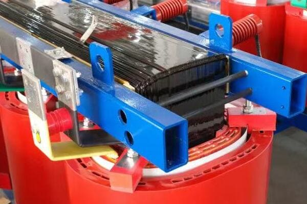
In this guide, I’ll take you on a journey inside a transformer, explaining each component in simple terms. Whether you’re an engineer, a project manager, or simply curious about the technology that powers our world, this article will give you a clear understanding of transformer internals. Let’s demystify these essential devices together.
What Are the Main Internal Parts of a Transformer?
Have you ever looked at a transformer and wondered what’s actually inside that metal box? You’re not alone. Many people, even those working with electrical systems, are unclear about the internal structure of these crucial devices. But what if understanding these components could help you make better decisions about power distribution in your projects?
The main internal parts of a transformer are the core, windings, and insulation system. The core, typically made of laminated steel sheets, provides a path for magnetic flux. Windings, consisting of primary and secondary coils, transfer energy between circuits. The insulation system, which may include oil, paper, or resin, prevents short circuits and manages heat. Additional components include terminals for connections, a cooling system, and protective devices like Buchholz relays in larger units.
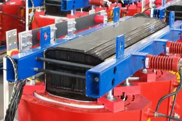
Key Components of a Transformer
Let’s break down the main internal parts:
- Core
- Windings
- Insulation System
- Terminals and Bushings
- Cooling System
Core
The magnetic heart of the transformer:
- Made of thin laminated steel sheets
- Provides a low-reluctance path for magnetic flux
- Shapes include E-I, U-I, or toroidal designs
I recently inspected a disassembled 1000kVA transformer. The core’s laminated structure was fascinating – hundreds of thin steel sheets stacked together, each coated with insulating material to reduce eddy current losses.
Windings
Conducting the electrical magic:
- Primary winding: Connects to input voltage
- Secondary winding: Delivers output voltage
- Made of copper or aluminum wire
During a factory tour, I observed the winding process for a large transformer. The precision in layering each turn of wire, ensuring proper insulation between layers, was impressive and crucial for the transformer’s performance.
Insulation System
Protecting and cooling:
- In oil-filled transformers: Mineral oil and paper insulation
- In dry-type transformers: Air, resin, or other solid insulators
- Prevents short circuits and manages heat dissipation
Here’s a quick comparison of insulation types:
| Transformer Type | Primary Insulation | Characteristics |
|---|---|---|
| Oil-filled | Mineral oil + paper | Excellent cooling, high dielectric strength |
| Dry-type | Epoxy resin or air | Environmentally friendly, fire-resistant |
Terminals and Bushings
Connecting to the outside world:
- Bushings: Insulated passages for conductors
- Terminals: Connection points for external circuits
Cooling System
Managing heat for longevity:
- Oil-filled: Radiators or fans for oil circulation
- Dry-type: Natural air circulation or forced-air cooling
Key points about transformer internal parts:
- The core provides a path for magnetic flux transfer
- Windings transform voltage levels through electromagnetic induction
- Insulation systems prevent short circuits and manage heat
- Terminals and bushings allow for safe external connections
- Cooling systems are crucial for maintaining optimal operating temperatures
In my experience, understanding these internal components is crucial for effective transformer management. I recall a case where a client was experiencing frequent overheating issues with their transformer. By examining the internal structure, we discovered that the insulation system had degraded, reducing its heat dissipation efficiency. This knowledge allowed us to address the root cause rather than just treating symptoms.
For example, in a recent project involving the selection of transformers for a new data center, our understanding of internal components led us to choose a specific dry-type design with enhanced cooling capabilities. This choice was crucial given the high ambient temperatures and continuous load requirements of the facility.
As we move on to discuss the transformer core in more detail, keep these basic components in mind. Understanding how they interact will help you grasp the overall function and efficiency of these essential devices.
The Transformer Core: Material, Shape, and Magnetic Function?
Have you ever wondered why transformer cores are made of specific materials or shaped in particular ways? Many people overlook the importance of the core, focusing only on ratings and size. But what if understanding the core could help you choose more efficient transformers or diagnose issues more effectively?
The transformer core is typically made of thin laminations of silicon steel, also known as electrical steel or CRGO (Cold Rolled Grain Oriented) steel. Its primary function is to provide a low-reluctance path for magnetic flux, facilitating energy transfer between windings. Common core shapes include E-I, U-I, and toroidal designs, each offering different efficiency and manufacturing trade-offs. The core’s material and construction significantly impact the transformer’s efficiency, affecting factors like no-load losses and magnetizing current.
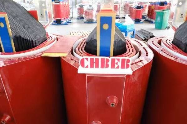
Key Aspects of Transformer Cores
Let’s examine the main features:
- Core Materials
- Core Shapes and Designs
- Magnetic Function
- Impact on Transformer Efficiency
- Manufacturing Considerations
Core Materials
Optimizing magnetic properties:
- Silicon Steel (CRGO): Most common, excellent magnetic properties
- Amorphous Metal: Higher efficiency, but more expensive
- Ferrite: Used in high-frequency applications
I recently visited a transformer manufacturing plant where they were experimenting with amorphous metal cores. The reduction in core losses was impressive, though the material’s brittleness presented unique manufacturing challenges.
Core Shapes and Designs
Balancing efficiency and practicality:
- E-I Core: Common in smaller transformers, easy to assemble
- U-I Core: Better flux distribution, used in larger units
- Toroidal Core: Highest efficiency, but more difficult to manufacture
During a recent project, we compared E-I and toroidal core designs for a series of 500kVA transformers. While the toroidal cores offered slightly better efficiency, the E-I design was chosen for its easier maintenance and lower manufacturing cost.
Magnetic Function
Understanding the core’s role:
- Provides a low-reluctance path for magnetic flux
- Concentrates magnetic field to maximize coupling between windings
- Minimizes magnetic flux leakage
Here’s a simplified view of how different core materials perform:
| Core Material | Advantages | Disadvantages |
|---|---|---|
| Silicon Steel | Cost-effective, good performance | Higher losses than advanced materials |
| Amorphous Metal | Very low core losses | More expensive, challenging to manufacture |
| Ferrite | Excellent for high frequencies | Limited power handling capacity |
Impact on Transformer Efficiency
Core’s influence on performance:
- Affects no-load losses (core losses)
- Influences magnetizing current
- Determines transformer’s overall efficiency
Manufacturing Considerations
Balancing performance and producibility:
- Lamination thickness affects both losses and manufacturing complexity
- Core assembly methods impact production speed and cost
- Material choice influences tooling and handling requirements
Key points about transformer cores:
- Material choice significantly impacts efficiency and cost
- Core shape affects flux distribution and manufacturing ease
- The core’s primary function is to provide a path for magnetic flux
- Core design directly influences transformer efficiency
- Manufacturing considerations play a role in core selection
In my experience, the choice of core material and design can have a profound impact on transformer performance. I recall a project where we were tasked with upgrading transformers in an old industrial facility. By replacing the old silicon steel cores with modern, high-grade electrical steel, we achieved a significant reduction in core losses, leading to improved overall efficiency and reduced operating costs.
For example, in a recent renewable energy project, we specified transformers with amorphous metal cores for the main step-up units. Despite the higher initial cost, this choice was justified by the lower losses, which were particularly beneficial given the variable nature of wind power generation. The improved efficiency translated to measurable increases in energy output over the project’s lifetime.
As we move on to discuss transformer windings, keep in mind how the core interacts with these components. Understanding this relationship is key to grasping the overall function and efficiency of transformers.
Windings: Primary vs Secondary and the Role of Copper or Aluminum?
Have you ever wondered why some transformers use copper windings while others use aluminum? Or why the primary and secondary windings are designed differently? These choices can significantly impact a transformer’s performance, cost, and lifespan. But how do you know which option is best for your application?
Transformer windings consist of primary and secondary coils, responsible for voltage transformation. The primary winding receives input voltage, while the secondary delivers the output. Copper and aluminum are the most common winding materials, each with distinct advantages. Copper offers better conductivity and compact design but at a higher cost. Aluminum is lighter and more economical but requires larger windings for the same capacity. The choice between these materials, along with winding design (e.g., layer, disc, or helical), affects the transformer’s efficiency, size, and price.
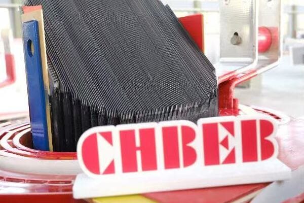
Key Aspects of Transformer Windings
Let’s examine the main features:
- Primary vs Secondary Windings
- Copper vs Aluminum Conductors
- Winding Designs and Configurations
- Impact on Transformer Performance
- Economic Considerations
Primary vs Secondary Windings
Understanding the basics:
- Primary Winding: Connected to input voltage source
- Secondary Winding: Delivers transformed voltage to the load
- Turn ratio determines voltage transformation
I recently inspected a 2000kVA transformer where the primary winding had significantly fewer turns of thicker wire compared to the secondary. This visual representation of the turns ratio principle was a great practical example of transformer theory in action.
Copper vs Aluminum Conductors
Choosing the right material:
- Copper: Higher conductivity, smaller size, better heat dissipation
- Aluminum: Lighter weight, lower cost, larger size for same capacity
During a recent project, we had to decide between copper and aluminum windings for a series of distribution transformers. While copper offered better performance, the aluminum option provided significant cost savings without compromising on the required efficiency standards.
Winding Designs and Configurations
Optimizing for different applications:
- Layer Winding: Common in low-voltage applications
- Disc Winding: Used in high-voltage transformers
- Helical Winding: Offers good short-circuit strength
Here’s a comparison of winding materials:
| Material | Advantages | Disadvantages |
|---|---|---|
| Copper | Higher conductivity, Compact design | More expensive, Heavier |
| Aluminum | Lower cost, Lighter weight | Larger size, Higher resistance |
Impact on Transformer Performance
How windings affect efficiency:
- Conductor material influences load losses
- Winding design affects short-circuit strength
- Insulation between turns impacts voltage withstand capability
Economic Considerations
Balancing cost and performance:
- Material prices fluctuate, affecting overall transformer cost
- Lifecycle cost analysis often favors copper for long-term applications
- Aluminum can be more economical for certain voltage classes and sizes
Key points about transformer windings:
- Primary and secondary windings serve distinct functions in voltage transformation
- The choice between copper and aluminum impacts performance and cost
- Various winding designs are used to optimize for different applications
- Winding characteristics significantly affect transformer efficiency and reliability
- Economic factors play a crucial role in winding material selection
In my experience, the choice of winding material and design can have far-reaching implications. I recall a project for a large industrial facility where we initially specified aluminum windings to reduce costs. However, after conducting a detailed lifecycle cost analysis, including efficiency losses and potential replacement costs, we ultimately chose copper windings. The higher initial investment was justified by long-term energy savings and improved reliability.
For example, in a recent renewable energy project, we used a hybrid approach. The main step-up transformers used copper windings for maximum efficiency, while the smaller distribution transformers in the solar farm used aluminum windings to balance cost and performance. This strategic use of different winding materials helped optimize the overall system efficiency while managing project costs.
As we move on to discuss transformer insulation systems, keep in mind how windings interact with both the core and insulation. Understanding these relationships is crucial for grasping the overall design and performance of transformers.
Transformer Insulation System: How It Works and Why It Matters?
Have you ever considered what keeps the high-voltage components of a transformer from short-circuiting? The insulation system is a critical yet often overlooked aspect of transformer design. But why is it so important, and how does it actually work to keep transformers safe and efficient?
The transformer insulation system is a crucial component that prevents electrical breakdown between windings, core, and other conductive parts. It typically consists of liquid (oil) or solid (resin, paper) materials with high dielectric strength. In oil-filled transformers, mineral oil combined with cellulose paper provides both insulation and cooling. Dry-type transformers use materials like epoxy resin or Nomex paper. The insulation system not only prevents short circuits but also manages heat dissipation, protects against moisture, and significantly influences the transformer’s lifespan and reliability.
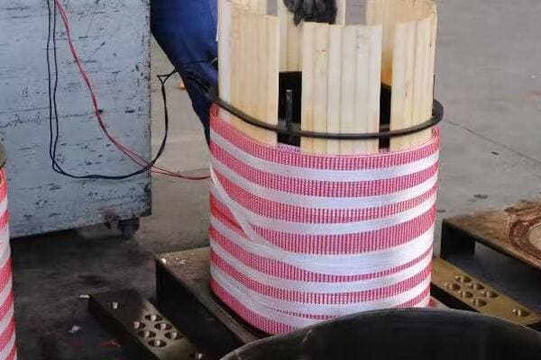
Key Aspects of Transformer Insulation
Let’s examine the main features:
- Types of Insulation Systems
- Functions of Insulation
- Oil-Filled vs Dry-Type Insulation
- Aging and Maintenance of Insulation
- Impact on Transformer Performance and Lifespan
Types of Insulation Systems
Common insulation materials:
- Liquid Insulation: Mineral oil, silicone oil, natural esters
- Solid Insulation: Cellulose paper, Nomex paper, epoxy resin
- Combination Systems: Oil-paper insulation in oil-filled transformers
I recently inspected a 30-year-old oil-filled transformer where the oil had maintained its insulating properties remarkably well. This experience highlighted the longevity and effectiveness of well-maintained liquid insulation systems.
Functions of Insulation
Multi-faceted role in transformer operation:
- Electrical Insulation: Prevents short circuits between conductive parts
- Heat Dissipation: Transfers heat from windings to cooling systems
- Moisture Protection: Shields critical components from humidity
- Mechanical Support: Provides structural integrity to windings
During a recent factory tour, I observed the intricate process of applying epoxy resin insulation to dry-type transformer windings. The precision required to ensure complete coverage and void-free insulation was impressive.
Oil-Filled vs Dry-Type Insulation
Comparing insulation systems:
- Oil-Filled: Excellent cooling and insulation, but potential environmental concerns
- Dry-Type: Environmentally friendly, fire-resistant, but typically lower capacity
Here’s a quick comparison:
| Aspect | Oil-Filled Insulation | Dry-Type Insulation |
|---|---|---|
| Cooling Efficiency | Excellent | Good |
| Environmental Risk | Higher (oil leaks) | Minimal |
| Fire Safety | Lower | Higher |
| Maintenance | Regular oil testing required | Minimal maintenance |
Aging and Maintenance of Insulation
Ensuring long-term reliability:
- Oil Degradation: Monitored through regular oil analysis
- Paper Deterioration: Accelerated by heat, moisture, and oxygen
- Dry-Type Aging: Affected by environmental factors and load cycles
Impact on Transformer Performance and Lifespan
Critical role in long-term operation:
- Insulation Quality: Directly affects transformer’s voltage withstand capability
- Thermal Management: Influences loading capacity and efficiency
- Lifespan Determination: Often the limiting factor in transformer longevity
Key points about transformer insulation systems:
- Insulation prevents electrical breakdown and manages heat
- Different types of insulation suit various transformer designs and applications
- Oil-filled and dry-type systems have distinct advantages and challenges
- Proper maintenance of insulation is crucial for transformer longevity
- Insulation quality significantly impacts overall transformer performanceIn my experience, the choice and maintenance of insulation systems can make or break a transformer’s performance and lifespan. I recall a case where a client was experiencing frequent transformer failures in a humid, coastal environment. Upon investigation, we discovered that the insulation system was not adequately protected against moisture ingress. By upgrading to a more suitable insulation system with enhanced moisture resistance, we significantly improved the transformers’ reliability and extended their operational life.
For example, in a recent project for a data center, we specified dry-type transformers with advanced epoxy resin insulation. This choice was driven by the need for high fire safety standards and minimal maintenance requirements in a critical facility. The enhanced insulation system not only met the stringent safety requirements but also provided excellent thermal management, crucial for the continuous high-load operation typical in data centers.
As we move on to visually compare the internals of dry-type and oil-immersed transformers, keep in mind how the insulation system integrates with other components. Understanding this integration is key to appreciating the overall design and functionality of different transformer types.
Visual Overview: What’s Inside a Dry Type vs Oil Immersed Transformer?
Have you ever wondered how dry type and oil immersed transformers differ internally? Many people struggle to visualize these differences, which can lead to confusion when selecting or maintaining transformers. But what if you could see inside both types, side by side?
Dry type and oil immersed transformers have distinct internal structures. Dry type transformers feature exposed or resin-encapsulated windings, with air or epoxy resin as the primary insulation and cooling medium. They often have an open structure or are enclosed in a ventilated cabinet. Oil immersed transformers, conversely, have their core and windings submerged in insulating oil within a sealed tank. They typically include additional components like radiators for cooling, an expansion tank (conservator) for oil volume changes, and various monitoring devices like oil level indicators and pressure relief valves.
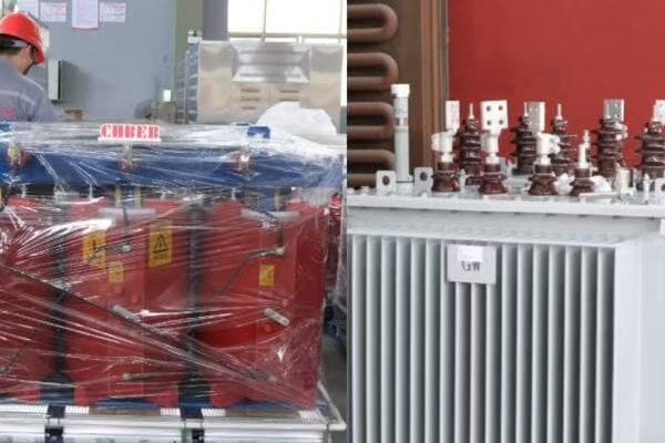
Key Differences in Internal Structure
Let’s compare the main internal components:
- Core and Winding Arrangement
- Insulation and Cooling System
- Enclosure and External Components
- Monitoring and Protection Devices
- Size and Space Requirements
Core and Winding Arrangement
Structural differences:
- Dry Type: Often visible windings, sometimes resin-encapsulated
- Oil Immersed: Core and windings fully submerged in oil
I recently had the opportunity to compare a 1000kVA dry type transformer with an oil immersed unit of the same capacity. The stark contrast in their internal layouts was fascinating – the dry type’s exposed windings versus the oil-filled tank of the immersed unit.
Insulation and Cooling System
Different approaches to insulation and heat management:
- Dry Type: Air or solid insulation (e.g., epoxy resin), often with forced air cooling
- Oil Immersed: Oil serves as both insulator and coolant, often with external radiators
During a factory tour, I observed the manufacturing process for both types. The precision required in resin casting for dry type transformers was as impressive as the meticulous oil filling and sealing process for oil immersed units.
Enclosure and External Components
Visible differences in design:
- Dry Type: Often in ventilated cabinets or with exposed components
- Oil Immersed: Sealed tank with external components like radiators and conservators
Here’s a quick comparison of external features:
| Feature | Dry Type Transformer | Oil Immersed Transformer |
|---|---|---|
| Main Enclosure | Ventilated cabinet or open frame | Sealed oil tank |
| Cooling System | Fans (if forced air) | Radiators, sometimes with fans |
| Expansion System | Not required | Conservator tank |
| Monitoring Devices | Temperature sensors | Oil level gauge, pressure relief valve |
Monitoring and Protection Devices
Different safety and monitoring needs:
- Dry Type: Temperature monitors, sometimes partial discharge sensors
- Oil Immersed: Oil level indicators, pressure relief devices, Buchholz relay
Size and Space Requirements
Comparing footprints and installation needs:
- Dry Type: Generally more compact, suitable for indoor installation
- Oil Immersed: Larger footprint, often requires containment area for potential oil leaks
Key points about the internal differences:
- Core and winding arrangements differ significantly between types
- Insulation and cooling methods are fundamentally different
- External components vary based on the cooling and insulation needs
- Monitoring and protection devices are tailored to each type’s specific risks
- Size and installation requirements can differ substantially
In my experience, understanding these internal differences is crucial for proper selection and installation. I recall a project where a client initially wanted to replace an old oil immersed transformer with a dry type unit in the same location. However, after reviewing the internal structures and space requirements, we realized that significant modifications to the installation site would be necessary. This insight helped the client make a more informed decision about whether to upgrade or maintain the existing transformer type.
For example, in a recent hospital expansion project, we chose dry type transformers for their fire safety advantages and lower maintenance requirements. The ability to install these units closer to the load centers, due to their compact size and absence of oil, allowed for a more efficient power distribution design throughout the facility.
As we conclude our exploration of transformer internals, remember that understanding these structural differences is key to making informed decisions about transformer selection, installation, and maintenance. Whether you’re an engineer, facility manager, or project planner, this knowledge can help you optimize your power distribution systems for safety, efficiency, and reliability.
Why Understanding Transformer Structure Helps with Selection and Maintenance?
Have you ever wondered why some transformers fail prematurely or why certain types are preferred for specific applications? The key often lies in understanding the internal structure of transformers. But how exactly does this knowledge translate into better selection and maintenance practices?
Understanding transformer structure is crucial for optimal selection and maintenance. It helps in choosing the right type (dry or oil-immersed) for specific environments, assessing cooling needs based on load profiles, and anticipating maintenance requirements. Knowledge of core and winding materials aids in evaluating efficiency and long-term costs. Familiarity with insulation systems helps predict lifespan and maintenance needs. This understanding enables more informed decisions during procurement, more effective troubleshooting during operation, and more efficient maintenance scheduling, ultimately leading to improved reliability and cost-effectiveness of power distribution systems.
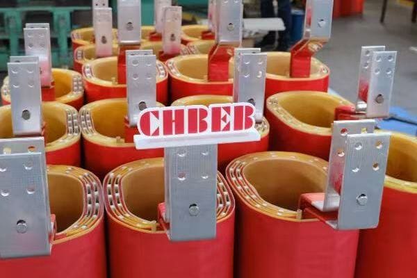
Key Benefits of Understanding Transformer Structure
Let’s explore how this knowledge helps:
- Improved Selection Process
- Enhanced Maintenance Practices
- Better Troubleshooting Capabilities
- Optimized Performance and Efficiency
- Increased Safety and Reliability
Improved Selection Process
Making informed choices:
- Matching transformer type to environmental conditions
- Selecting appropriate cooling systems based on load profiles
- Choosing the right insulation class for expected operating temperatures
I recently advised a client on transformer selection for a coastal industrial facility. Understanding the internal structure helped us choose a design with enhanced corrosion resistance for the core and windings, crucial for the salt-laden environment.
Enhanced Maintenance Practices
Tailoring maintenance to specific needs:
- Focusing on critical components based on transformer type
- Anticipating wear and degradation patterns
- Scheduling appropriate maintenance intervals
During a recent maintenance review for a large data center, our knowledge of dry-type transformer internals allowed us to develop a more targeted and efficient maintenance plan, focusing on critical areas like winding insulation and cooling systems.
Better Troubleshooting Capabilities
Diagnosing issues more effectively:
- Identifying potential failure points based on structural knowledge
- Interpreting test results with a deeper understanding of internal components
- Quickly pinpointing the root cause of performance issues
Here’s how structural knowledge aids in common troubleshooting scenarios:
| Issue | How Structural Knowledge Helps |
|---|---|
| Overheating | Identify if it’s a core, winding, or cooling system problem |
| Unusual Noise | Determine if it’s core vibration or winding movement |
| Insulation Failure | Assess whether it’s due to overloading, aging, or environmental factors |
Optimized Performance and Efficiency
Maximizing transformer capabilities:
- Understanding load capacity in relation to core and winding design
- Optimizing cooling systems based on internal heat generation patterns
- Balancing efficiency with cost based on core material properties
Increased Safety and Reliability
Enhancing operational safety:
- Recognizing potential failure modes based on structural weaknesses
- Implementing appropriate safety measures for different transformer types
- Improving reliability through targeted upgrades and replacements
Key points about the importance of understanding transformer structure:
- It enables more informed and appropriate transformer selection
- Maintenance can be tailored to specific transformer designs
- Troubleshooting becomes more efficient and accurate
- Performance and efficiency can be optimized based on structural knowledge
- Safety and reliability are enhanced through better understanding of potential issues
In my experience, a deep understanding of transformer structure can lead to significant improvements in both selection and maintenance practices. I recall a case where a manufacturing plant was experiencing frequent transformer failures. By analyzing the internal structure of the failing units, we discovered that the core design was not suitable for the harmonic-rich environment of the plant. This insight led to the selection of transformers with more appropriate core designs, dramatically improving reliability and reducing downtime.
For example, in a recent renewable energy project, our understanding of transformer internals guided us in selecting units with amorphous metal cores. While more expensive initially, these transformers offered superior efficiency, especially under the variable load conditions typical of wind and solar generation. This choice led to measurable improvements in overall system efficiency and reduced long-term operational costs.
Remember, whether you’re selecting a new transformer or maintaining existing ones, a solid grasp of internal structures and components is invaluable. It empowers you to make decisions that enhance performance, extend equipment life, and ultimately contribute to more reliable and efficient power distribution systems.
Conclusion
Understanding the internal structure of transformers – core, windings, and insulation – is crucial for effective selection, operation, and maintenance. This knowledge helps in choosing the right transformer for specific applications, optimizing performance, and implementing targeted maintenance strategies. By grasping these fundamentals, you can make more informed decisions, troubleshoot issues effectively, and ultimately ensure more reliable and efficient power distribution systems.
Remember, at chbeb-ele, we’re not just sharing information – we’re empowering you to be part of the solution in creating a secure, clean, and efficient energy future. Let’s continue this journey together.
Are you struggling to budget for your power distribution project? You’re not alone. Many engineers and project managers find it challenging to estimate dry type transformer costs accurately. But what if you had a comprehensive guide to 2025 pricing trends at your fingertips?
In 2025, dry type transformer prices vary significantly based on capacity (kVA) and voltage level. A 250kVA, 11/0.4kV transformer typically costs $2,000-$2,700, while a 1000kVA unit ranges from $6,500-$9,000. Prices increase with voltage class, with 33kV units costing about 20% more than 10kV equivalents. Factors like cooling method (AN vs AF), certifications (CE, IEC), and raw material costs (copper, silicon steel) also impact pricing. Chinese manufacturers offer competitive rates, with prices varying based on customization and export requirements.
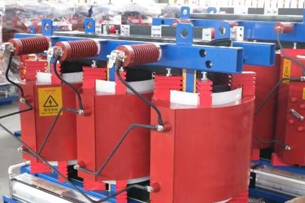
In this comprehensive guide, I’ll walk you through the key factors influencing dry type transformer prices in 2025. We’ll explore typical cost ranges for various kVA ratings and voltage classes, discuss how certifications and cooling methods affect pricing, and provide insights on sourcing from Chinese manufacturers. Whether you’re planning a small commercial installation or a large industrial project, this article will give you the knowledge to make informed decisions and optimize your budget.
What Affects the Price of a Dry Type Transformer in 2025?
Are you finding it difficult to understand why dry type transformer quotes can vary so widely? You’re not alone. Many buyers struggle to identify the key factors driving costs. But what specific elements have the most significant impact on dry type transformer pricing in 2025?
The price of a dry type transformer in 2025 is influenced by several key factors: raw material costs (especially copper and silicon steel), kVA rating, voltage class, insulation level, cooling method, and required certifications. Higher voltage classes (e.g., 33kV vs 10kV) increase costs due to more complex winding structures and insulation requirements. Advanced cooling methods (AF vs AN) and stringent certifications (CE, IEC, KEMA) also drive up prices. Additionally, customization requirements, production volume, and global market conditions play roles in determining the final cost.
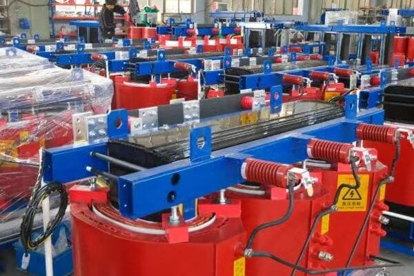
Key Cost Factors for Dry Type Transformers
Let’s break down the main elements affecting pricing:
- Raw Materials
- Capacity and Voltage Class
- Insulation and Cooling
- Certifications and Standards
- Customization and Production Volume
Raw Materials
Core components driving costs:
- Copper: Primary material for windings, subject to market fluctuations
- Silicon Steel: Used for the transformer core, impacts efficiency and cost
- Insulation Materials: Resin and other materials for electrical isolation
I recently analyzed the cost structure of a 1000kVA dry type transformer. The copper windings alone accounted for nearly 40% of the total material cost, highlighting the significant impact of raw material prices on overall transformer pricing.
Capacity and Voltage Class
Scaling costs with power requirements:
- kVA Rating: Higher capacity generally means higher cost
- Voltage Class: Higher voltages require more insulation and complex designs
During a recent project, we compared quotes for 11kV and 33kV transformers of the same kVA rating. The 33kV unit was approximately 25% more expensive due to the additional insulation and more complex winding structure required.
Insulation and Cooling
Ensuring performance and longevity:
- Insulation Class: Higher temperature ratings increase cost
- Cooling Method: Forced air (AF) cooling is more expensive than natural air (AN)
Here’s a quick comparison of cooling methods:
| Cooling Method | Cost Impact | Typical Application |
|---|---|---|
| AN (Air Natural) | Base cost | Indoor, lower capacity |
| AF (Air Forced) | +10-15% | Higher capacity, industrial |
| AFWF (Water Cooled) | +25-30% | Specialized, high capacity |
Certifications and Standards
Meeting regulatory requirements:
- IEC 60076: International standard for power transformers
- CE Marking: Required for European market entry
- KEMA or CESI Type Testing: Adds credibility but increases cost
Customization and Production Volume
Balancing specificity and economy:
- Custom Designs: Tailored solutions often cost more
- Production Quantity: Larger orders can reduce per-unit costs
Key points affecting dry type transformer prices in 2025:
- Raw material costs, especially copper, have a significant impact
- Higher kVA ratings and voltage classes increase prices
- Advanced cooling methods and insulation classes add to the cost
- Certifications and compliance with international standards affect pricing
- Customization requirements can significantly influence the final price
In my experience, understanding these factors is crucial for accurate budgeting and negotiation. I recall a project where we initially underestimated the cost impact of upgrading from an AN to an AF cooling system for a 2000kVA transformer. This oversight led to budget adjustments later in the project. By thoroughly considering all these factors upfront, we’ve since been able to provide more accurate cost estimates and avoid surprises.
For example, in a recent renewable energy project, we needed dry type transformers with special corrosion resistance for a coastal environment. By working closely with the manufacturer to understand the cost implications of these customizations, we were able to optimize our design choices and balance performance requirements with budget constraints.
As we move on to discuss specific price ranges by kVA rating, keep these cost factors in mind. Understanding their influence will help you interpret the pricing data more effectively and make more informed decisions for your projects.
Dry Type Transformer Price List by kVA Rating (Typical Ranges in USD)?
Are you struggling to find reliable pricing information for dry type transformers across different capacities? You’re not alone. Many buyers find it challenging to estimate costs accurately for their projects. But what if you had a comprehensive price list covering the most common kVA ratings used in various applications?
Dry type transformer prices in 2025 vary significantly based on kVA rating. Typical ranges include: 100kVA ($1,200-$1,800), 250kVA ($2,000-$2,700), 500kVA ($3,500-$4,800), 1000kVA ($6,500-$9,000), 1600kVA ($9,500-$12,500), and 2500kVA ($14,000-$18,000). These prices are for standard 11kV/0.4kV configurations with basic certifications. Factors like higher voltage classes, advanced cooling methods, and additional certifications can increase costs. Prices are FOB China and may vary based on specific project requirements and market conditions.
Detailed Price Breakdown by kVA Rating
Let’s examine the typical price ranges for common dry type transformer capacities:
- 100kVA – 250kVA Range
- 500kVA – 1000kVA Range
- 1600kVA – 2500kVA Range
- Factors Influencing Price Within Each Range
- Application Scenarios and Selection Guidance
100kVA – 250kVA Range
Ideal for small to medium applications:
- 100kVA: $1,200 – $1,800
- 250kVA: $2,000 – $2,700
- Common voltage: 11/0.4 kV
- Typical cooling: AN (Air Natural)
I recently worked on a project for a small office complex where we installed several 250kVA dry type transformers. The cost-effectiveness of these units, combined with their compact size and low maintenance requirements, made them perfect for the distributed power needs of the building.
500kVA – 1000kVA Range
Suitable for larger commercial and light industrial use:
- 500kVA: $3,500 – $4,800
- 1000kVA: $6,500 – $9,000
- Common voltage: 11/0.4 kV or 22/0.4 kV
- Typical cooling: AF (Air Forced)
During a recent industrial park development, we utilized multiple 1000kVA transformers to provide reliable power distribution across various manufacturing facilities. The flexibility of these units in handling diverse load profiles proved invaluable.
1600kVA – 2500kVA Range
Designed for heavy industrial and utility applications:
- 1600kVA: $9,500 – $12,500
- 2500kVA: $14,000 – $18,000
- Common voltage: 33/0.4 kV
- Cooling: AF with enhanced features
Here’s a detailed price breakdown for high-capacity units:
| kVA Rating | Voltage Class | Cooling | Price Range (USD) | Typical Application |
|---|---|---|---|---|
| 1600kVA | 22kV or 33kV | AF | $9,500 – $12,500 | Large factories, data centers |
| 2000kVA | 33kV | AF | $12,000 – $15,000 | Utility substations |
| 2500kVA | 33kV | AF (with fans) | $14,000 – $18,000 | Grid-connected systems, heavy industry |
Factors Influencing Price Within Each Range
Understanding price variations:
- Copper vs. Aluminum windings: Copper typically 15-20% more expensive
- Insulation class: Higher temperature ratings increase cost
- IP rating: Enhanced protection (e.g., IP23 vs IP21) adds to the price
- Accessories: Monitoring systems, special terminals can affect cost
Application Scenarios and Selection Guidance
Matching capacity to needs:
- 100-250kVA: Ideal for small commercial buildings, schools
- 500-1000kVA: Suitable for shopping malls, medium-sized factories
- 1600-2500kVA: Best for large industrial facilities, utility applications
Key points about dry type transformer pricing by kVA rating:
- Prices increase significantly with higher kVA ratings
- Voltage class and cooling method impact cost within each kVA range
- Material choices (e.g., copper vs. aluminum) affect pricing
- Higher capacity units often come with advanced features, reflected in the price
- Selecting the right capacity involves balancing current needs and future growth
In my experience, carefully matching transformer capacity to actual load requirements can lead to significant cost savings. I recall a project where a client initially requested a 2000kVA unit based on conservative estimates. After conducting a detailed load analysis, we determined that a 1600kVA transformer would suffice, even accounting for future growth. This adjustment resulted in substantial savings without compromising system reliability.
For example, in a recent renewable energy project, we used a combination of 1000kVA and 1600kVA dry type transformers to optimize cost and performance across different sections of a large solar farm. This approach allowed us to tailor the power distribution system to varying load densities within the project site.
As we move on to discuss how voltage class impacts pricing, keep these kVA-based price ranges in mind. Understanding the relationship between capacity, features, and cost will help you make more informed decisions when specifying transformers for your projects.
Price Impact by Voltage Class: 6kV, 10kV, 20kV, and 33kV Compared?
Are you finding it challenging to understand how different voltage classes affect dry type transformer prices? You’re not alone. Many buyers struggle to grasp the cost implications of selecting higher voltage ratings. But how exactly do prices vary across common voltage classes like 6kV, 10kV, 20kV, and 33kV?
Voltage class significantly impacts dry type transformer pricing. Compared to 10kV units, 6kV transformers are typically 5-10% cheaper due to simpler insulation requirements. 20kV units are generally 10-15% more expensive than 10kV equivalents, reflecting increased insulation and winding complexity. 33kV transformers can cost 20-30% more than 10kV models of the same kVA rating, due to more sophisticated design, enhanced insulation, and stricter testing requirements. These price differences are consistent across various kVA ratings, though the impact may be more pronounced in higher capacity units.
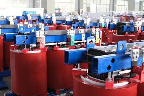
Comparing Prices Across Voltage Classes
Let’s examine the price impact for each voltage class:
- 6kV Transformers
- 10kV Transformers (Baseline)
- 20kV Transformers
- 33kV Transformers
- Factors Driving Price Differences
6kV Transformers
Lower voltage, lower cost:
- Typically 5-10% cheaper than 10kV equivalents
- Simpler insulation design
- Often used in industrial applications with shorter distribution distances
I recently worked on a project for a manufacturing facility where we opted for 6kV dry type transformers. The lower voltage class allowed for cost savings without compromising on the power distribution needs of the facility, given its compact layout.
10kV Transformers (Baseline)
Standard for many distribution networks:
- Used as a baseline for price comparisons
- Common in commercial and light industrial applications
- Balance of cost and performance for many projects
During a recent urban development project, we extensively used 10kV dry type transformers. Their cost-effectiveness and compatibility with the local distribution network made them an ideal choice for powering various commercial and residential buildings.
20kV Transformers
Meeting higher voltage requirements:
- Typically 10-15% more expensive than 10kV units
- Increased insulation and winding complexity
- Growing popularity in some regions for enhanced distribution efficiency
Here’s a comparison of price impacts across voltage classes:
| Voltage Class | Price Impact | Typical Application |
|---|---|---|
| 6kV | -5% to -10% | Industrial, short-distance distribution |
| 10kV | Baseline | Commercial, light industrial |
| 20kV | +10% to +15% | Medium voltage distribution, some residential |
| 33kV | +20% to +30% | Heavy industrial, utility substations |
33kV Transformers
High voltage, premium pricing:
- 20-30% more expensive than 10kV equivalents
- Sophisticated design and enhanced insulation
- Used in utility-scale projects and heavy industrial applications
Factors Driving Price Differences
Understanding the cost variations:
- Insulation requirements: Higher voltages need more robust insulation
- Winding complexity: More turns and sophisticated designs for higher voltages
- Testing and certification: Stricter requirements for higher voltage classes
- Material quality: Premium materials often needed for higher voltage units
Key points about voltage class impact on transformer pricing:
- Price increases significantly with higher voltage classes
- 6kV offers cost savings for suitable applications
- 10kV serves as a cost-effective standard for many projects
- 20kV balances enhanced distribution with moderate price increase
- 33kV commands a premium but offers benefits for high-power applications
In my experience, carefully considering the voltage class can lead to significant project optimizations. I recall a case where a client initially specified 33kV transformers for a large commercial development, assuming higher voltage meant better efficiency. After a detailed analysis of the load distribution and future growth projections, we determined that 20kV units would suffice. This adjustment resulted in substantial cost savings without compromising on power quality or future expandability.
For example, in a recent renewable energy project, we used a combination of 20kV and 33kV dry type transformers at different points in the power distribution system. The 20kV units were cost-effective for local distribution within the solar farm, while 33kV transformers were used for the main grid connection, balancing cost with the need for higher voltage at the interconnection point.
As we move on to discuss how certifications and cooling methods affect transformer pricing, keep these voltage class considerations in mind. Understanding the cost implications of different voltage ratings will help you make more informed decisions when specifying transformers for your projects, ensuring you get the right balance of performance and cost-effectiveness.
Certifications and Cooling Methods That Increase Cost?
Are you wondering why some dry type transformers come with significantly higher price tags? You’re not alone. Many buyers are surprised by the cost impact of certain certifications and cooling methods. But which specific factors can substantially increase the price of a dry type transformer?
Certifications like CE marking and IEC 60076 compliance can increase dry type transformer costs by 5-15%, depending on the extent of testing required. KEMA or CESI type test certifications can add another 3-8% to the price due to rigorous third-party verification. Regarding cooling methods, forced air (AF) cooling typically increases costs by 8-15% compared to natural air (AN) cooling, due to additional components and controls. Enhanced protection ratings, such as IP23 or higher, can add 5-10% to the cost. These factors compound, potentially increasing the overall price by 20-30% for a fully certified, high-spec unit.
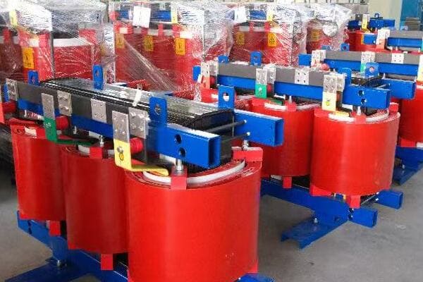
Key Cost-Increasing Factors
Let’s examine the main elements that can drive up transformer prices:
- International Certifications
- Cooling Methods
- Protection Ratings
- Special Testing Requirements
- Customization and Advanced Features
International Certifications
Ensuring global compliance and quality:
- CE Marking: Essential for European market, adds 5-10% to cost
- IEC 60076 Compliance: International standard, increases price by 3-7%
- KEMA or CESI Type Testing: Premium certification, adds 3-8% to cost
I recently managed a project exporting dry type transformers to the EU. The CE certification process, including additional testing and documentation, increased our costs by about 8%. However, this certification was crucial for market entry and customer confidence.
Cooling Methods
Balancing performance and cost:
- AN (Air Natural): Baseline cooling method
- AF (Air Forced): 8-15% cost increase over AN
- AFWF (Air Forced Water Forced): Can increase cost by 20-25%
During a recent industrial project, we opted for AF cooling on a 2000kVA transformer. While this increased the cost by about 12%, it allowed for a more compact design and better performance in the high-ambient temperature environment of the factory.
Protection Ratings
Enhancing durability and safety:
- IP21 (Standard): Baseline protection
- IP23: 5-7% cost increase
- IP54 and above: 10-15% or more, depending on requirements
Here’s a comparison of protection ratings and their cost impacts:
| IP Rating | Cost Increase | Typical Application |
|---|---|---|
| IP21 | Baseline | Indoor, controlled environments |
| IP23 | +5-7% | Light industrial, some outdoor |
| IP54 | +10-15% | Dusty or wet environments |
| IP65 | +15-20% | Harsh industrial or outdoor settings |
Special Testing Requirements
Verifying performance and reliability:
- Routine Tests: Included in base price
- Type Tests: Can add 5-10% to cost
- Special Tests (e.g., short-circuit withstand): 3-7% additional cost
Customization and Advanced Features
Meeting specific project needs:
- Custom Voltage Ratings: 3-5% cost increase
- Advanced Monitoring Systems: 5-10% additional cost
- Special Materials (e.g., low-loss core): 7-12% price increase
Key points about cost-increasing factors:
- International certifications are often necessary but add significant cost
- Advanced cooling methods increase price but improve performance
- Higher protection ratings are crucial for certain environments but come at a premium
- Special testing can substantially impact cost but may be required for critical applications
- Customization and advanced features offer benefits but at higher prices
In my experience, carefully evaluating these factors against project requirements can lead to optimal cost-performance balance. I recall a project where a client initially requested the highest level of certification and protection rating for an indoor installation. After a thorough risk assessment, we determined that a more standard configuration with targeted enhancements would meet all safety and performance needs at a significantly lower cost.
For example, in a recent data center project, we justified the additional cost of AF cooling and advanced monitoring systems for the dry type transformers. While this increased the initial investment by about 20%, it provided crucial benefits in terms of reliability, efficiency, and remote management capabilities, which were essential for the critical nature of the facility.
As we move on to discuss recommended Chinese manufacturers offering transparent pricing and OEM support, keep these cost-increasing factors in mind. Understanding their impact will help you better evaluate different manufacturers’ offerings and ensure you’re getting the best value for your specific requirements.
Recommended Chinese Manufacturers Offering Transparent Pricing and OEM Support?
Are you finding it challenging to identify reliable Chinese manufacturers of dry type transformers that offer both competitive pricing and quality assurance? You’re not alone. Many international buyers struggle to navigate the vast landscape of Chinese suppliers. But which manufacturers stand out for their transparency, OEM capabilities, and export-friendly practices?
Top recommended Chinese dry type transformer manufacturers known for transparent pricing and strong OEM support include CHBEB, CHINT, TBEA, and Sieyuan Electric. These companies offer a range of transformers from 100kVA to 3150kVA, with voltage classes up to 35kV. They provide comprehensive documentation, including detailed quotations, technical specifications, and necessary certifications like ISO 9001, IEC 60076, and CE marking. Many offer customization options, English-speaking support teams, and experience in major export markets across Asia, Africa, and the Middle East.
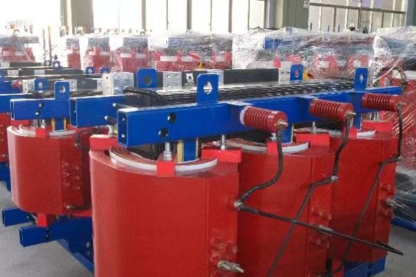
Leading Dry Type Transformer Manufacturers in China
Let’s examine the top recommended suppliers:
- CHBEB (China Bei Er Bian)
- CHINT
- TBEA
- Sieyuan Electric
CHBEB (China Bei Er Bian)
Specializing in customized solutions:
- Capacity range: 250-2500kVA
- Voltage classes: Up to 35kV
- Key strengths: OEM capabilities, export-oriented, competitive pricing
- Certifications: ISO 9001, IEC, CE
I recently worked with CHBEB on a project requiring custom dry type transformers for a harsh industrial environment. Their willingness to adapt designs and provide detailed documentation greatly simplified the procurement process.
CHINT
Comprehensive power solution provider:
- Capacity range: 100-2500kVA
- Voltage classes: Up to 35kV
- Key strengths: Wide product range, stable pricing, global distribution network
- Certifications: ISO, CE, KEMA
During a recent large-scale commercial development project, we sourced multiple dry type transformers from CHINT. Their transparent pricing structure and ability to handle bulk orders efficiently were key factors in our decision.
TBEA
High-end transformer solutions:
- Capacity range: 500-3150kVA
- Voltage classes: Up to 35kV
- Key strengths: Advanced technology, experience in large-scale projects
- Certifications: CNAS, ISO
Here’s a quick comparison of these manufacturers:
| Manufacturer | Capacity Range | Key Strength | Price Competitiveness |
|---|---|---|---|
| CHBEB | 250-2500kVA | Customization, OEM | High |
| CHINT | 100-2500kVA | Wide range, stable pricing | Very High |
| TBEA | 500-3150kVA | High-end solutions | Moderate |
| Sieyuan | 630-2500kVA | GIS integration | High |
Sieyuan Electric
Integrated power solutions:
- Capacity range: 630-2500kVA
- Voltage classes: Up to 35kV
- Key strengths: GIS integration capabilities, smart grid solutions
- Certifications: ISO 14001, IEC
Key points about recommended Chinese manufacturers:
- They offer a wide range of capacities and voltage classes
- Most provide comprehensive documentation and export support
- Certifications and compliance with international standards are common
- Many have experience in key export markets
- OEM and customization capabilities are available
In my experience, these manufacturers have consistently demonstrated their ability to meet international quality standards while offering competitive pricing. I recall a project where we needed dry type transformers for a series of data centers across Southeast Asia. By working with CHBEB, we were able to develop a custom design that met the specific cooling and efficiency requirements of the project, all while staying within budget constraints.
For example, in a recent renewable energy project, we utilized transformers from CHINT for solar farm connections. Their ability to provide a large number of standardized units quickly, along with all necessary certifications for the target market, was crucial in meeting the project’s aggressive timeline.
As we move on to discuss how to get a custom quotation based on your project specs, keep these manufacturer profiles in mind. Understanding their strengths and specialties will help you target your inquiries more effectively and potentially find the best match for your specific transformer needs.
Get a Custom Quotation Based on Your Project Specs?
Are you ready to take the next step and obtain accurate pricing for your dry type transformer needs? Getting a tailored quotation is crucial for budget planning and supplier selection. But what information do you need to provide to ensure you receive the most accurate and competitive quotes?
To get a custom quotation for dry type transformers, provide detailed specifications including kVA rating, primary and secondary voltage levels, frequency, cooling method (AN/AF), and required protection rating (IP class). Specify any special requirements such as low-loss design, monitoring systems, or specific certifications needed (e.g., CE, IEC 60076). Include information about the project location, quantity needed, and preferred delivery timeframe. Most reputable manufacturers offer quick quote turnaround, typically within 24-48 hours for standard configurations, and can provide detailed technical proposals for more complex requirements.
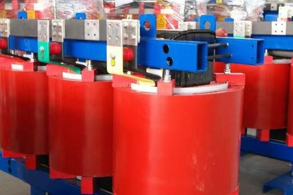
Key Steps to Obtain a Custom Quotation
Let’s break down the process:
- Preparing Your Specifications
- Choosing the Right Manufacturers
- Submitting Your Request for Quotation (RFQ)
- Evaluating and Comparing Quotes
- Next Steps After Receiving Quotes
Preparing Your Specifications
Gathering essential information:
- kVA rating and voltage levels (primary/secondary)
- Frequency (50Hz or 60Hz)
- Cooling method (AN or AF)
- Protection rating (IP class)
- Any special requirements or certifications needed
I recently helped a client prepare specifications for a series of dry type transformers for a new commercial complex. By clearly defining requirements like a 1000kVA capacity, 11kV/400V voltage, AF cooling, and IP23 protection, we ensured the quotes we received were accurate and comparable.
Choosing the Right Manufacturers
Selecting potential suppliers:
- Research manufacturers with relevant experience
- Consider those with a strong export track record
- Look for suppliers offering transparent pricing and good communication
Submitting Your Request for Quotation (RFQ)
Crafting a comprehensive inquiry:
- Clearly state all technical requirements
- Specify quantity needed and desired delivery timeframe
- Include any specific testing or documentation requirements
Here’s a checklist of information to include in your RFQ:
| Information | Example |
|---|---|
| kVA Rating | 1000kVA |
| Voltage | 11kV/400V |
| Frequency | 50Hz |
| Cooling Method | AF (Air Forced) |
| IP Rating | IP23 |
| Quantity | 5 units |
| Delivery Timeframe | Within 12 weeks |
| Special Requirements | Low-loss design, SCADA compatible |
Evaluating and Comparing Quotes
Analyzing received proposals:
- Compare technical specifications to ensure they meet your requirements
- Look at pricing structure and what’s included (e.g., testing, documentation)
- Consider delivery times and payment terms
- Evaluate after-sales support and warranty offerings
Next Steps After Receiving Quotes
Moving forward with your project:
- Clarify any questions or ambiguities in the quotes
- Request sample documentation or test reports if needed
- Consider factory visits for large or critical projects
- Negotiate terms and prepare for order placement
Key points for obtaining custom quotations:
- Prepare detailed and accurate specifications
- Choose manufacturers with relevant experience and good reputations
- Submit comprehensive RFQs to ensure accurate quotes
- Carefully evaluate and compare received quotations
- Follow up on any questions and prepare for next steps
In my experience, providing clear and comprehensive information in your RFQ is crucial for receiving accurate and comparable quotes. I recall a project where initial quotes varied widely due to ambiguous specifications. By refining our RFQ with more precise requirements, including specific loss levels and noise constraints, we received much more consistent and useful quotations from suppliers.
For example, in a recent renewable energy project, we needed dry type transformers with special corrosion resistance for a coastal environment. By clearly specifying this requirement in our RFQ, along with the necessary capacity and voltage ratings, we received detailed proposals from manufacturers, including specialized designs and materials to meet the challenging environmental conditions.
Remember, the quality of the information you provide directly impacts the accuracy and usefulness of the quotations you receive. Take the time to prepare a thorough RFQ, and don’t hesitate to ask questions or request additional information from manufacturers. This diligence in the quoting process can save significant time and resources as your project moves forward.
Conclusion
Dry type transformer pricing in 2025 varies significantly based on kVA rating, voltage class, certifications, and cooling methods. Prices range from $1,200 for 100kVA units to over $18,000 for 2500kVA transformers. Higher voltage classes and advanced features increase costs. When sourcing, consider reputable Chinese manufacturers known for quality and competitive pricing. Always provide detailed specifications for accurate quotes. Careful evaluation of your project needs against these factors will ensure optimal transformer selection and cost-effectiveness.
Remember, at chbeb-ele, we’re not just sharing information – we’re empowering you to be part of the solution in creating a secure, clean, and efficient energy future. Let’s continue this journey together.
Are you struggling to find reliable box type transformer suppliers in China? You’re not alone. Many buyers face challenges in identifying manufacturers that can meet international standards and export requirements. But what if you had a comprehensive guide to the top Chinese suppliers, their capabilities, and export track records?
This article ranks the top 10 box type transformer manufacturers in China for 2025, focusing on their export capabilities, certifications, and product strengths. Leading companies like CHBEB, CHINT, and TBEA offer a range of box transformers from 250kVA to 3150kVA, with voltage classes up to 110kV. These manufacturers hold key certifications such as ISO 9001, IEC 62271-202, and CE marking, catering to markets in the Middle East, Africa, Southeast Asia, and beyond. The guide also covers factors buyers should consider when selecting a Chinese supplier.
In this comprehensive guide, I’ll walk you through the essential information about box type transformers and their manufacturers in China. We’ll explore what makes these transformers popular for export, key factors to consider when choosing a supplier, and provide detailed profiles of the top manufacturers. Whether you’re a project manager, procurement specialist, or electrical engineer, this article will provide valuable insights to help you make informed decisions in sourcing box type transformers from China.
What Is a Box Type Transformer and Why It’s Popular for Export?
Have you ever wondered why box type transformers are becoming increasingly common in international power distribution projects? These compact units are revolutionizing how we approach medium-voltage power distribution. But what exactly are box type transformers, and why are they in such high demand for export markets?
A box type transformer, also known as a compact substation or CSS, is an integrated power distribution unit that combines a transformer, high-voltage switchgear, and low-voltage panel within a single enclosure. These units typically handle voltage levels from 11kV to 33kV and capacities ranging from 250kVA to 2500kVA. Box type transformers are popular for export due to their compact design, ease of installation, and versatility across various applications. They comply with international standards like IEC 62271-202, making them suitable for global markets, especially in rapidly developing regions of the Middle East, Southeast Asia, and Africa.
Key Features and Export Advantages
Let’s break down the main characteristics that make box type transformers attractive for international markets:
- Integrated Design
- Compact Footprint
- Ease of Installation
- Versatility in Applications
- Compliance with International Standards
Integrated Design
All-in-one power distribution solution:
- Combines transformer, HV switchgear, and LV panel
- Reduces need for separate components and interconnections
- Simplifies project planning and execution
I recently worked on a project in the Middle East where we used box type transformers to upgrade a commercial district’s power distribution. The integrated design significantly reduced installation time and complexity compared to traditional setups.
Compact Footprint
Space-saving advantages:
- Ideal for urban environments with limited space
- Suitable for rooftop installations in high-rise buildings
- Reduces overall substation footprint
During a recent consultation for a smart city project in Southeast Asia, the compact nature of box transformers allowed us to strategically place power distribution points without disrupting the urban landscape.
Ease of Installation
Streamlining deployment:
- Factory-assembled and tested before shipment
- Minimal on-site work required
- Reduces overall project timeline and labor costs
Here’s a quick comparison of installation times:
| Transformer Type | Typical Installation Time | On-Site Work Required |
|---|---|---|
| Box Type | 1-2 days | Minimal (placement and connection) |
| Traditional Setup | 1-2 weeks | Extensive (assembly and wiring) |
Versatility in Applications
Meeting diverse needs:
- Suitable for residential, commercial, and industrial use
- Adaptable for renewable energy projects (solar and wind farms)
- Customizable for specific environmental conditions (e.g., desert, coastal)
Compliance with International Standards
Ensuring global acceptability:
- Designed to meet IEC 62271-202 standards
- Often CE marked for European market compliance
- Adaptable to regional standards (e.g., ANSI for North America)
Key points about box type transformers and their export popularity:
- They offer an integrated, compact solution for medium-voltage distribution
- Significantly reduce installation time and complexity
- Versatile enough to suit various applications and environments
- Comply with international standards, facilitating global acceptance
- Ideal for rapidly developing markets with growing power needs
In my experience, the popularity of box type transformers in export markets stems from their ability to address multiple challenges simultaneously. I recall a project in Africa where we needed to quickly deploy reliable power distribution in a rapidly growing urban area. The box type transformers we sourced from China not only met the technical requirements but also allowed for a much faster rollout compared to traditional substation designs.
For example, in a recent renewable energy project in Southeast Asia, we utilized box type transformers for solar farm connections. Their compact design and ease of installation were crucial in minimizing the project’s environmental footprint while meeting strict local regulations.
As we move on to discuss key factors buyers look for in Chinese box transformer manufacturers, keep these export advantages in mind. Understanding why these transformers are in demand will help you better evaluate potential suppliers and their offerings.
Key Factors Buyers Look for in Chinese Box Transformer Manufacturers?
Are you finding it challenging to evaluate Chinese box transformer manufacturers? You’re not alone. Many international buyers struggle to identify the most crucial factors when selecting a supplier. But what specific criteria should you focus on to ensure you’re partnering with a reliable and capable manufacturer?
Key factors buyers consider when choosing Chinese box transformer manufacturers include certifications (ISO 9001, IEC 60076, CE marking), production capabilities, customization options, export experience, and after-sales support. Buyers look for manufacturers that provide comprehensive documentation, including detailed technical drawings and type test reports. Delivery timelines, OEM/ODM capabilities, and experience in specific export markets are also crucial. Additionally, factors like remote monitoring interface support and the ability to meet specific environmental or regulatory requirements play significant roles in the selection process.
Essential Criteria for Supplier Evaluation
Let’s examine the main factors to consider:
- Certifications and Compliance
- Manufacturing Capabilities
- Customization and Design Flexibility
- Export Experience and Support
- Technical Documentation and Testing
Certifications and Compliance
Ensuring quality and standards adherence:
- ISO 9001 for quality management systems
- IEC 60076 and IEC 62271-202 compliance for transformers and substations
- CE marking for European market access
- Additional certifications like KEMA or CNAS for enhanced credibility
I recently led a procurement team for a major utility project where we made certifications a top priority. This focus on verified compliance significantly reduced quality issues and simplified the approval process with local authorities.
Manufacturing Capabilities
Assessing production capacity and quality:
- Annual production volume
- Advanced manufacturing equipment and processes
- Quality control measures throughout production
During a recent factory visit in China, I was impressed by a manufacturer’s automated production lines and rigorous in-process quality checks, which directly correlated with the consistency of their output.
Customization and Design Flexibility
Meeting specific project needs:
- Ability to modify designs for unique requirements
- Range of voltage and capacity options
- Adaptability to different environmental conditions (e.g., high temperature, high humidity)
Here’s a quick overview of customization options to look for:
| Aspect | Customization Options |
|---|---|
| Voltage Class | 11kV, 22kV, 33kV, others as needed |
| Capacity | 250kVA to 2500kVA, custom ratings available |
| Enclosure | IP ratings from IP23 to IP65 for various environments |
| Cooling | ONAN, ONAF, custom cooling solutions |
Export Experience and Support
Facilitating international transactions:
- Track record in key export markets (e.g., Middle East, Africa, Southeast Asia)
- Understanding of international shipping and documentation requirements
- Multilingual technical support and after-sales service
Technical Documentation and Testing
Providing comprehensive product information:
- Detailed technical drawings (PDF and CAD formats)
- Type test reports from accredited laboratories
- Routine test reports for each unit
- Operation and maintenance manuals in relevant languages
Key points buyers look for in Chinese box transformer manufacturers:
- Relevant certifications and compliance with international standards
- Robust manufacturing capabilities and quality control processes
- Flexibility in customization to meet specific project requirements
- Proven export experience and support for international buyers
- Comprehensive technical documentation and testing reports
In my experience, thoroughly evaluating these factors is crucial for successful procurement. I recall a case where a client initially focused solely on price, overlooking some of these key criteria. This led to issues with product quality and export documentation, causing significant project delays. By developing a comprehensive supplier evaluation checklist based on these factors, we’ve since been able to streamline our procurement process and ensure more reliable outcomes.
For example, in a recent project requiring box transformers for a harsh coastal environment, we prioritized manufacturers with proven experience in similar conditions and the ability to provide custom corrosion-resistant enclosures. This focused approach led us to a supplier who not only met our technical specifications but also offered valuable insights on long-term maintenance in corrosive environments.
As we move on to review the top 10 box type transformer manufacturers in China, keep these selection criteria in mind. Understanding what to look for will help you better evaluate each manufacturer’s strengths and suitability for your specific project needs.
Top 10 Box Type Transformer Manufacturers in China (2025 Edition)?
Are you struggling to identify the best box type transformer manufacturers in China? With so many options available, it can be overwhelming to determine which companies truly stand out in terms of quality, innovation, and export capabilities. But which manufacturers are leading the industry in 2025, and what makes them stand out?
The top 10 box type transformer manufacturers in China for 2025 include industry leaders like CHBEB, CHINT, TBEA, and XD Group, alongside specialized players such as Sieyuan Electric and Taikai Electric. These companies offer a range of box transformers from 250kVA to 5000kVA, with voltage classes up to 110kV. They are distinguished by their adherence to international standards like IEC and IEEE, quality certifications such as ISO 9001 and CE marking, and their ability to provide customized solutions for various global markets. Many have strong export presences in regions like the Middle East, Africa, Southeast Asia, and along the Belt and Road initiative countries.
Leading Box Type Transformer Manufacturers in China
Let’s examine the top 10 companies and their key strengths:
- CHBEB (China Bei Er Bian)
- CHINT
- TBEA
- XD Group
- Sieyuan Electric
- Taikai Electric
- Pinggao Group
- Tianwei Group
- Hengyang Transformer
- Shanghai Electric
CHBEB (China Bei Er Bian)
Specializing in customized solutions:
- Capacity range: 630-2500kVA
- Voltage classes: 11kV-33kV
- Key strengths: OEM capabilities, export-oriented, high IP ratings
- Certifications: ISO 9001, CE, IEC 62271-202
- Main export regions: Middle East, Africa, Russia
I recently visited CHBEB’s manufacturing facility and was impressed by their advanced testing lab for box transformers, ensuring high-quality products for international markets.
CHINT
Comprehensive power solution provider:
- Capacity range: 250-2500kVA
- Voltage classes: 10kV-20kV
- Key strengths: Wide product range, fast delivery, global distribution network
- Certifications: ISO, CE, KEMA
- Main export regions: Southeast Asia, Africa, South America
During a recent project in Southeast Asia, we sourced box transformers from CHINT. Their ability to provide a large quantity of standardized units quickly was crucial for meeting our tight project timeline.
TBEA
High-end transformer solutions:
- Capacity range: 630-3150kVA
- Voltage classes: 10kV-110kV
- Key strengths: Ultra-high voltage expertise, EPC capabilities
- Certifications: KEMA, ISO, CNAS
- Main export regions: Central Asia, Belt and Road countries
Here’s a quick overview of TBEA’s box transformer offerings:
| Aspect | Specification |
|---|---|
| Capacity Range | 630kVA to 3150kVA |
| Voltage Classes | 10kV, 35kV, 110kV |
| Key Features | Smart grid compatible, high efficiency |
| Typical Applications | Large-scale utility projects, industrial zones |
XD Group
Comprehensive power equipment manufacturer:
- Capacity range: 1250-5000kVA
- Voltage classes: 35kV-110kV
- Key strengths: Full range of power equipment, strong in EPC projects
- Certifications: ISO, IEC, GB
- Main export regions: Domestic market, Middle East, Africa
Key points about China’s top box transformer manufacturers:
- They offer a wide range of capacities and voltage classes
- Many have strong capabilities in customization and R&D
- Adherence to international standards and certifications is common
- Several specialize in specific applications or markets
- Most have significant experience in both domestic and export markets
In my experience, these top manufacturers have consistently demonstrated their ability to meet diverse project requirements. I recall a large-scale urban development project where we sourced box transformers from multiple Chinese manufacturers on this list. By leveraging the specific strengths of each company – such as CHBEB’s customization capabilities for unique installation requirements and CHINT’s cost-effective standard units for widespread distribution – we were able to optimize the overall power distribution system while managing costs effectively.
For example, in a recent renewable energy project involving both solar and wind power integration, we utilized box transformers from Taikai Electric for solar farm connections and units from Sieyuan Electric for the wind farm. This combination allowed us to address the specific requirements of each renewable source while ensuring overall system compatibility.
As we move on to profile CHBEB, a certified box transformer manufacturer with a strong global export track record, keep in mind how each of these top manufacturers brings unique strengths to the table. Understanding their specializations can help you make more informed decisions when selecting suppliers for your specific box transformer needs.
CHBEB Profile: Certified Box Transformer Manufacturer with Global Export Track Record?
Are you curious about how Chinese manufacturers are adapting to meet international standards in box transformer production? CHBEB’s approach to global markets offers an intriguing case study. But what makes their manufacturing and export strategies stand out, particularly for international clients?
CHBEB (China Bei Er Bian) has established itself as a leading certified manufacturer of box type transformers with a strong global export presence. With production facilities in Wenzhou and Nanjing, CHBEB offers box transformers ranging from 630kVA to 2500kVA, with voltage classes up to 33kV. They hold key certifications including ISO 9001, IEC 62271-202, and CE marking. CHBEB’s export portfolio includes projects in Qatar (33kV substations), Iraq (port facility CSS), and Indonesia (solar grid integration). They provide comprehensive documentation, including detailed drawings, CE certificates, and type test reports, with typical delivery times of 30-45 days for standard units.
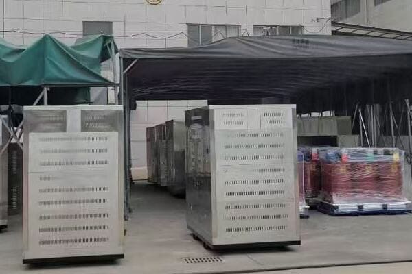
CHBEB’s Approach to Global Box Transformer Manufacturing
Let’s examine key aspects of CHBEB’s operations:
- Manufacturing Capabilities
- Product Range and Customization
- Certifications and Quality Control
- Export Experience and Project Examples
- Documentation and Support Services
Manufacturing Capabilities
State-of-the-art production facilities:
- Wenzhou plant: Focus on standard box transformer production
- Nanjing facility: Specializes in customized and high-capacity units
- Annual production capacity exceeding 5000 units
I recently toured CHBEB’s Nanjing facility and was impressed by their automated production lines and rigorous testing procedures, which ensure consistent quality for export markets.
Product Range and Customization
Meeting diverse global needs:
- Standard range: 630kVA to 2500kVA, 11kV to 33kV
- Customization options: Special voltage ratings, unique enclosure designs
- Adaptability to various environmental conditions (desert, coastal, high altitude)
During a recent consultation for a Middle Eastern project, CHBEB’s engineering team proposed a custom box transformer design with enhanced cooling capabilities and corrosion-resistant materials, showcasing their ability to adapt to challenging environments.
Certifications and Quality Control
Ensuring global compliance:
- ISO 9001:2015 certified quality management system
- IEC 62271-202 compliance for high-voltage/low-voltage prefabricated substations
- CE marking for European market access
- Additional type tests from recognized laboratories (e.g., KEMA, CESI)
Here’s an overview of CHBEB’s key certifications:
| Certification | Scope | Relevance |
|---|---|---|
| ISO 9001:2015 | Quality Management | Global standard |
| IEC 62271-202 | Prefabricated Substations | Technical compliance |
| CE Marking | Product Safety | European market entry |
| Type Test Reports | Performance Verification | Project-specific requirements |
Export Experience and Project Examples
Proven global capabilities:
- Middle East: 33kV substations for Qatar infrastructure projects
- Iraq: Custom CSS (Compact Substations) for port facilities
- Indonesia: Box transformers for solar energy grid integration
- Africa: Various projects adapting to challenging environments and grid conditions
Documentation and Support Services
Comprehensive export assistance:
- Detailed technical drawings in PDF and CAD formats
- Full set of test reports and certificates
- Multilingual operation and maintenance manuals
- Remote monitoring interface support for smart grid applications
Key points about CHBEB’s box transformer manufacturing and export capabilities:
- Advanced manufacturing facilities with high annual production capacity
- Wide product range with strong customization abilities
- Comprehensive certifications ensuring global compliance
- Extensive export experience across diverse markets and applications
- Strong documentation and support services for international clients
In my experience, CHBEB’s approach to international markets sets them apart in the competitive landscape of Chinese box transformer manufacturers. I recall a challenging project in a remote area of Africa where we needed transformers that could withstand extreme heat and dust. CHBEB not only provided units with enhanced environmental protection but also offered valuable insights on long-term maintenance in harsh conditions, demonstrating their commitment to customer success beyond just product delivery.
For example, in a recent smart city project in Southeast Asia, we utilized CHBEB’s box transformers with integrated IoT capabilities. Their ability to provide both the hardware and the necessary interface protocols for remote monitoring and control was crucial in creating an efficient, future-proof power distribution network.
As we move on to discuss how to request quotations and verify certifications, keep in mind the comprehensive approach that leading manufacturers like CHBEB take towards international markets. Understanding these capabilities will help you formulate more effective inquiries and ensure you’re getting the most value from your chosen supplier.
How to Request Quotation and Verify Certifications?
Are you feeling overwhelmed by the process of requesting quotations and verifying certifications for box transformers from Chinese manufacturers? You’re not alone. Many buyers find this step challenging, but it’s crucial for ensuring you get the right product at the right price. So, what’s the most effective way to approach this process?
To request a quotation for box transformers, provide detailed specifications including capacity (kVA), voltage ratings, switchgear configuration, and enclosure requirements. Ask for a complete technical proposal including drawings (PDF and CAD), test reports, and a detailed bill of materials. For certification verification, request copies of ISO 9001, IEC compliance certificates, and CE marking documentation. Ensure these are current and issued by recognized bodies. Consider using third-party inspection services for additional verification. Always clarify delivery terms, warranty conditions, and after-sales support in your RFQ.
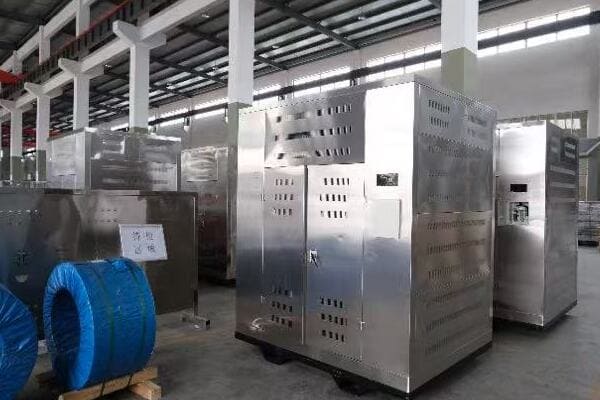
Key Steps in Requesting Quotations and Verifying Certifications
Let’s break down the process:
- Preparing Your Request for Quotation (RFQ)
- Essential Technical Specifications to Include
- Requesting and Evaluating Certifications
- Comparing Quotes and Technical Proposals
- Final Verification and Negotiation
Preparing Your Request for Quotation (RFQ)
Crafting a comprehensive inquiry:
- Clearly state project requirements and timeline
- Specify any special environmental or regulatory needs
- Request detailed technical proposals alongside pricing
I recently managed an RFQ process for a large industrial project. By providing a standardized template to all potential suppliers, we ensured we received comparable, detailed responses that significantly simplified our evaluation process.
Essential Technical Specifications to Include
Ensuring you get accurate quotes:
- Transformer capacity (kVA) and voltage ratings (primary/secondary)
- Required protection features and switchgear configuration
- Enclosure specifications (IP rating, material, color)
- Any special requirements (e.g., remote monitoring capabilities, specific standards compliance)
During a recent procurement for a solar farm project, we created a detailed specification sheet that included not just basic transformer parameters but also specific requirements for grid integration. This level of detail helped us identify suppliers who could truly meet our project’s unique needs.
Requesting and Evaluating Certifications
Verifying compliance and quality:
- Ask for copies of all relevant certificates (ISO 9001, IEC, CE)
- Verify the validity and scope of certifications
- Request type test reports from accredited laboratories
Here’s a checklist for certification verification:
| Certification | What to Check | Why It Matters |
|---|---|---|
| ISO 9001 | Validity date, issuing body | Ensures quality management system |
| IEC Compliance | Specific standards met, test reports | Confirms technical compliance |
| CE Marking | Declaration of Conformity, technical file | Essential for European market |
| Type Test Reports | Test parameters, issuing laboratory | Verifies performance claims |
Comparing Quotes and Technical Proposals
Making informed decisions:
- Create a standardized comparison matrix
- Evaluate technical specifications against your requirements
- Consider total cost of ownership, not just initial price
Final Verification and Negotiation
Ensuring the best deal:
- Clarify any ambiguities in quotes or technical proposals
- Negotiate terms, including delivery, warranty, and after-sales support
- Consider factory visits or third-party inspections for critical projects
Key points for effective quotation requests and certification verification:
- Prepare a comprehensive and clear RFQ
- Include all essential technical specifications in your request
- Always ask for and thoroughly verify relevant certifications
- Use a systematic approach to compare quotes and proposals
- Conduct final verifications and negotiations before committing
In my experience, a methodical approach to this process can save significant time and resources in the long run. I recall a case where a client rushed through the quotation process, focusing mainly on price. This led to misunderstandings about technical specifications and certification requirements, resulting in delays and additional costs. By implementing a structured RFQ process and thorough certification verification, we’ve since been able to avoid such issues and ensure smoother project executions.
For example, in a recent project requiring box transformers for a critical infrastructure application, we not only requested detailed quotations and certifications but also arranged for a third-party inspection of the manufacturer’s facilities. This extra step provided valuable insights into the manufacturer’s capabilities and quality control processes, giving us confidence in our final supplier selection.
Remember, the effort you put into crafting detailed RFQs and thoroughly verifying certifications pays off in the form of better-suited products, fewer surprises during project execution, and more reliable long-term performance of your box transformers.
Conclusion
Selecting the right box type transformer manufacturer from China requires careful consideration of factors including product range, certifications, export experience, and customization capabilities. Top manufacturers like CHBEB, CHINT, and TBEA offer diverse solutions catering to global markets. When requesting quotations, provide detailed specifications and always verify certifications. By following these guidelines, you can confidently source high-quality box transformers that meet your project’s specific needs and international standards.
Remember, at chbeb-ele, we’re not just sharing information – we’re empowering you to be part of the solution in creating a secure, clean, and efficient energy future. Let’s continue this journey together.
