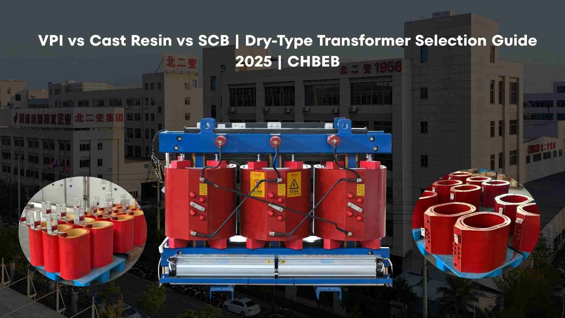
VPI vs. Cast Resin vs. SCB: Your Ultimate Guide to Dry Transformer Selection
Introduction
Picking the wrong dry transformer could cause it to overheat, make noise, and go over budget. A lot of people get the VPI transformer, cast resin transformer, and SCB transformer mixed up. This book explains technologies, analyzes their costs and performance, and gives you a useful decision tree to help you choose with confidence.
In-Depth Analysis: The Core Technology & Manufacturing Process of All Three
Misunderstanding fundamental technology results in incorrect specifications and the need for rework. Not being clear about insulation, heat routes, and production stages raises risk. The answer is to learn how each process works and what it means in real life before asking for estimates.
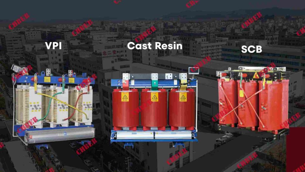
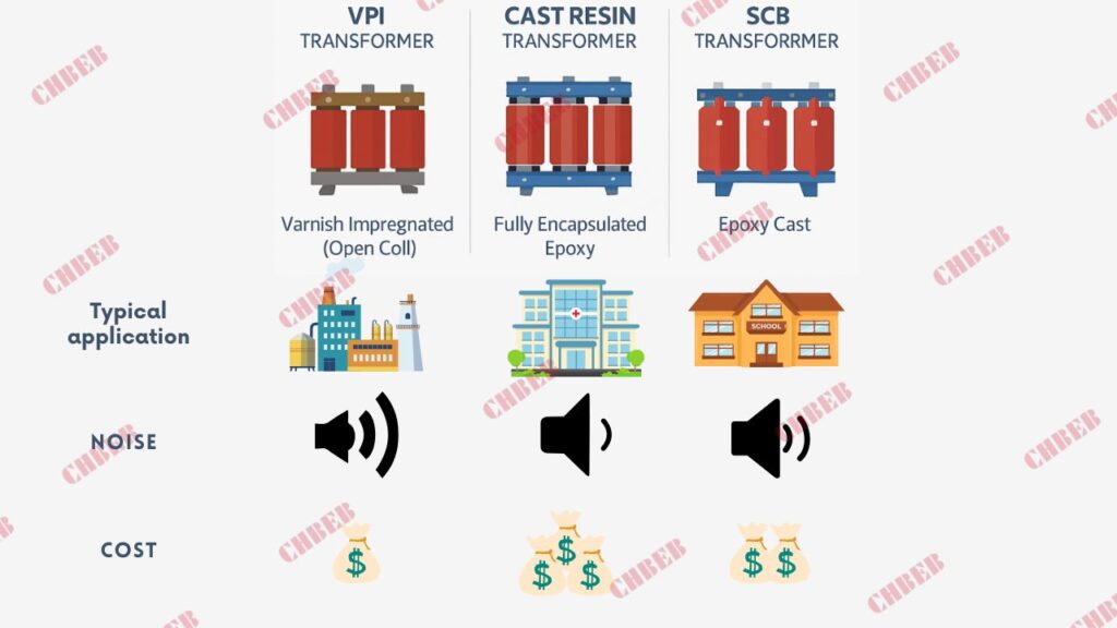
The Benefits of Vacuum Pressure Impregnation for VPI Dry Transformers1
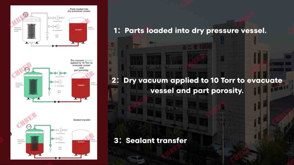
Step 1: Coils are dried in a vacuum. Step 2: They are then varnished under pressure. Step 3: They are baked several times to make a winding that is bonded and resistant to moisture.
- Open windings let heat escape easily.
- With the right process control, there is less partial discharge.
- Coils can be fixed, and field re-impregnation is possible.
Where it works best: industrial plants, retrofits, moderate pollution, and places where serviceability and value are important.
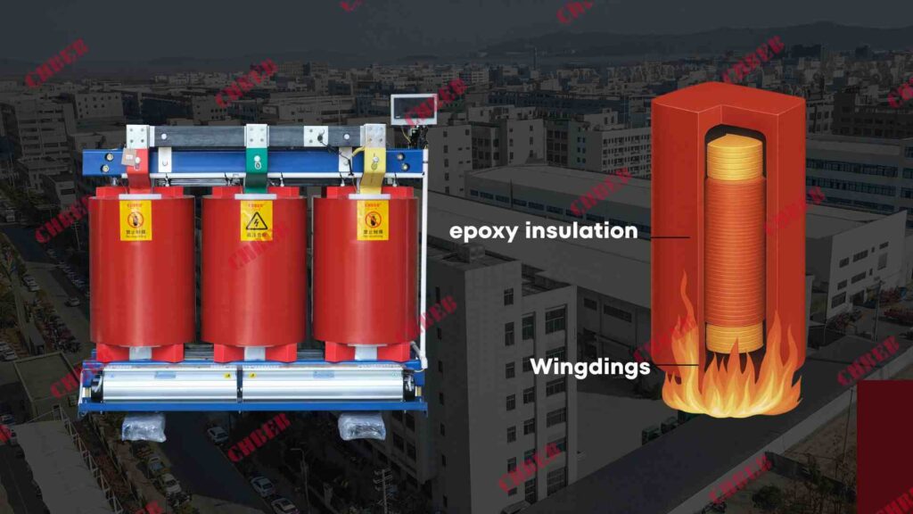
Cast Resin Transformers: Epoxy Resin Casting Works Better
Process: Under vacuum, epoxy is cast around the primary and secondary coils, making solid insulation with no holes that has great dielectric strength.
- Resistant to high levels of moisture and contaminants.
- Very little partial discharge; stable shape when short-circuit pressures are applied.
- Great fire behavior; less smoke and toxicity when the right resin systems are used.
Where it works best: indoor, fire-sensitive places like data centers, metros, hospitals, and commercial skyscrapers.
The SCB Series Transformers: The New Choice That Balances Cost and Performance
Process/Context: “SCB” usually stands for epoxy cast-resin dry transformers (such the SCB10/SCB11/SCB13 series) that are made to be as quiet and efficient as possible according to Chinese and IEC requirements..
- Levels of efficiency and sound quality that are best for building services.
- A lot of local supplies, low prices, and quick delivery timeframes.
- A good mix of performance, safety, and cost over the life of the product.
Where it shines: campuses, stores, light industry—projects that want to lose as little money as possible and get good value.
Performance, Cost & Application: A Multi-Dimensional Comparison for Better Decisions
If you solely look at unit price, your OPEX and downtime will go up. When people don’t understand ratings and surroundings, acceptance testing can go wrong. The solution is to compare on the criteria that matter for the whole life cycle, not just the initial cost.
At a Glance: Key Performance Metrics Comparison Table for Insulation and Noise
| Metric | VPI Transformer | Cast Resin Transformer | SCB Transformer2 (Cast Resin Families) |
|---|---|---|---|
| Insulation System | Varnish impregnated (open coil) | Fully encapsulated epoxy | Epoxy cast (series-optimized) |
| Moisture/Contamination | Good, needs ventilation discipline | Excellent, sealed coil faces | Excellent, building-optimized |
| Thermal Dissipation | Very good (air paths) | Good (through resin & ducts) | Good, optimized for low rise |
| Partial Discharge | Low with robust process | Very low; geometry is rigid | Very low; standard PD controls |
| Short-Circuit Strength | Good (mechanical bracing key) | Excellent (solid coil form) | Excellent (series-tested) |
| Fire Behavior/Smoke | No oil; low fire load | Superior with low-smoke resins | Superior in building services |
| Noise | Low–moderate (design dependent) | Low (rigid coils reduce hum) | Low (series acoustic focus) |
| Maintenance/Repair | Serviceable; rewinding possible | Minimal; repairs are harder | Minimal; field-proven spares |
| Lead Time | Short–medium | Medium | Short (common ratings stocked) |
| Relative CAPEX | $ | $$ | $–$$ (value-optimized) |
| Typical Price | ~USD 20–35/kVA | ~USD 30–50/kVA | ~USD 25–45/kVA |
| Best Fit | Industrial retrofits, value | Mission-critical indoor safety | Building MEP, campuses, light industry |
Buyer’s Quick Takeaway:
• Pick the VPI transformer if you want it to be easy to use and cheap.
• Choose a Cast Resin transformer if safety and fire resistance are your main priorities.
• Pick the SCB transformer if you want a good combination of performance and price.
• All three are widely used in Belt and Road projects in Southeast Asia, Africa, and the Middle East, where buyers seek quick delivery and conformity with IEC standards.
Typical Application Scenarios: Exactly What Your Project Needs
- For low fire load, low PD, and silent operation in data centers, hospitals, and subways, use Cast Resin or SCB.
- VPI for industrial and process lines where airflow is good, serviceability is important, and value is vital.
- SCB series for efficiency, sound quality, and low prices in universities, campuses, and commercial towers.
- Coastal areas or areas with high humidity: Cast Resin/SCB with anti-condensation procedures.
- For small spaces, make sure to choose ventilation plans that have been tested and that keep noise and temperature rise to a minimum.
- In Southeast Asian metro projects, SCB transformers are very popular. In African industrial retrofits, VPI transformers are utilized a lot. In Middle Eastern hospitals, Cast Resin transformers are becoming more popular for fire safety compliance.
Quick Selection Guide: Your Tree of Choices for Dry Transformers
- Define duty and risk: mission-critical indoor (Cast/SCB) vs. serviceable industrial (VPI).
- Check the environment: pollution/humidity → favor Cast/SCB; clean/ventilated → VPI is possible.
- Set goals for loss and noise: Cast/SCB series has strict restrictions, whereas VPI is cost-effective.
- Check the limits: room size, airflow, cable runs, fire code, and seismic class.
- Set the final specs: kVA, voltage, impedance, temperature rise, PD level, enclosure IP, and tests.
Common Questions & Purchasing Advice
Vague quotes and unclear specs lead to disputes and overruns. Not testing, PD limitations, or ventilation can cause failures. The answer is exact RFQs, verifiable paperwork, and terms of the contract that can be enforced.
FAQ: Answering Your Most Important Questions About Selection
Q1: Which is safer for buildings that are open to the public?
A cast resin transformer or a SCB transformer. They are great for hospitals, metros, and high-rise MEP rooms since they have solid epoxy coils, low smoke and toxicity, and low PD.
Q2: When is the VPI transformer better than the Cast Resin transformer?
VPI works well for industrial lines, retrofits, and projects that are on a tight budget and need good airflow and serviceability. It also makes repairs easier.
Q3: What PD (partial discharge) levels do I need to set?
Most purchasers want insulation that lasts longer and makes less noise, therefore follow IEC/GB standards and keep the voltage below 10 pC.
Q4: What should I do about areas near the seaside or with high humidity?
Use a Cast Resin or SCB transformer with heaters, IP enclosures, and regular checks.
Q5: How much does a typical dry type transformer cost in 2025?
The price of dry type transformers is between $20 and $50 per kVA, FOB China. A 1000 kVA SCB transformer (11/0.4 kV) usually costs between $25,000 and $40,000.
Q6: What tests should be included in the contract?
List the types of tests—routine, type, and special tests—along with explicit acceptance criteria.
Purchasing tips:
• Send out a one-page RFQ including kVA, voltages, impedance, temp rise, PD limit, noise, enclosure, cooling (AN/AF), testing, standards, and accessories.
• Ask for detailed quotes that include guaranteed losses (W), delivery, Incoterms, parts, and a warranty.
• Include the right to inspect (FAT/third-party), late delivery fees, and fines for going over budget.
• Verify certifications (ISO/IEC) and project references; request recent PD and temperature-rise reports.
👉 These practices help global buyers source reliable dry type transformers from China with confidence.
Conclusion
Choosing the right dry transformer is about matching technology to duty, environment, and lifecycle cost targets—not just picking the lowest bid.
- VPI transformers excel in industrial retrofits and value-focused projects where airflow and serviceability matter.
- Cast Resin transformers are the safest choice for hospitals, metros, and data centers, thanks to superior fire resistance and low PD.
- SCB series transformers balance efficiency, noise, and cost, making them ideal for campuses, commercial towers, and light industry.
✅ Final takeaway: Define your load, safety, and efficiency requirements, then select the transformer type that minimizes risk and maximizes ROI. Lock specifications, losses, and test guarantees in your contract to protect performance.
👉 Contact us for a tailored dry transformer selection plan with pricing, lead times, and technical advice—so your 2025 projects stay on budget, on schedule, and reliable.
- Understanding Vacuum Pressure Impregnation (VPI) Transformers ↩︎
- Global Transformer Market Analysis 2025 ↩︎
Learn More
Looking for the right dry-type transformer for your project? Download our latest product catalog or browse our product categories to find reliable solutions tailored to your needs.
The “Top 100” Myth Debunked: Your Ultimate Guide to Vetting Chinese Transformer Manufacturers
Introduction
There is illusory confidence in endless “Top 100” lists. Buyers look for names, but then they run across problems like mismatches, delays, and hidden fees. The answer is a vetting system that puts needs first and uses evidence to match providers to your scope, standards, and risk tolerance.
Why There Isn’t a Single “Best” Ranking: Debunking the Myth
Ranking tables don’t take into account your voltage class, kVA, losses, environment, timing, or after-sales needs. Too much dependency might cause overspec or failure. To address this, you need to figure out what “best” means for your project and then compare vendors based on those exact standards.
Search Intent Analysis: What Is the “Best” Transformer for You?
Distribution, GSU, step-up/step-down, rectifier, furnace, and traction are all functions.
Spec anchors include kVA, voltage class, impedance, cooling, assured losses, and noise.
Commercial anchors: Capex vs. Opex, delivery timeframe, warranty/service SLAs, and location constraints.
The Chinese Transformer Market: Top Players by Application Segment
Chinese Transformer Supplier Divides by Use
| Application Segment | Typical Supplier Profile | What They’re Good At | Key Watchouts |
|---|---|---|---|
| Utility / UHV & HVDC1 | State-owned groups, national labs | EHV/UHV, type tests, large bays | Longer planning cycles |
| Renewables (Wind/Solar GSUs) | Export-oriented mid-tier | Fast lead times, IEC docs, flexible MOQs | Validate loss guarantees |
| Industrial / Process | Regional specialists | MV distribution, custom accessories | After-sales capacity |
| Data Centers / Metro / Hospitals | Dry-type specialists | Low fire-load, low noise, indoor design | Thermal management & ventilation |
📌 Regional Outlook: Chinese transformer makers are big suppliers for Belt & Road markets, which include Southeast Asia, Africa, the Middle East, and Russia, in addition to their own projects. In these areas, affordable prices, reliable logistics, and established IEC certificates are frequently the most important factors. This makes mid-tier and regional firms attractive candidates.
Evaluate and Vet: How to Find Your Perfect Partner
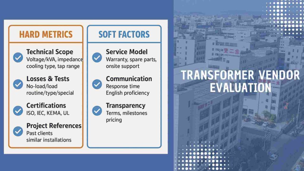
Hard Metrics: Technical Strength, Quality Certifications, and Experience on Projects
Voltage/kVA, impedance, temperature rise, cooling (AN/AF/ONAN/ONAF/ODAF), and tap range are all parts of the technical scope.
Losses and tests: No-load/load losses are guaranteed, and there are routine, type, and special tests with acceptance criteria.
ISO9001/14001/45001, IEC compliance, CE, and sectoral certifications (such KEMA2/UL) when they are needed.
References: installations with similar duties, grid/EPC projects, FAT reports, and clients that can be reached.
💡 Keep in mind that these factors are most important for EPC contractors, utilities, and big infrastructure buyers who need to follow the rules very closely.
Soft factors: service, communication, and clear pricing
Service model: warranty conditions, how long it takes to get spare parts, and when they can come to your site.
Communication: how quickly engineers respond, how well they write in English, and how they handle changes.
Transparency: explicit Incoterms, milestone plan, fines, and itemized offers.
The Rise of Smart and High-Efficiency Transformers: Trends to Watch in 2025
Higher efficiency classes: stricter loss targets are pushing upgrades to the core and winding.
Digitalization: sensors, thermal modeling, partial discharge, and diagnostics from afar.
Eco-fluids and safety: natural esters that are safe for the environment and fire.
Contracting shift: More customers are making payments based on performance testing and losses.
A Safe and Effective Way to Buy Things
Five Steps to Check Out a Transformer Supplier
- Define and RFQ: List kVA, voltage, losses, cooling, standards, FAT scope, and delivery.
- Evaluate and Compare: Make sure that technical offers, credentials, and references are all in line with one other; make sure that all offers are the same.
- Audit & Validate: Check certificates with the people who gave them to you, do an on-site or video audit, and make a quality control plan before the award.
- Contract and Safeguards: Set milestones, LDs, and a list of spare parts to protect against losses.
- Build, FAT, and Handover: Approve the drawings, watch the FAT, and make sure the packing, insurance, and customs documents are all in order.
Risk Management: Important Things to Know About Payment Security and Quality Control
Safety of payments: Use L/C or milestone payments that are linked to drawings, FAT, or shipment. Use an escrow account for spare parts.
QC checkpoints: ITP with hold/witness points; third-party (SGS/TÜV) inspections before shipping.
Control of documents: changes to drawings, material certificates, test records, and warranty contacts.
Logistics and insurance: checked packing specs, shock/tilt indications, all-risk freight protection, and a checklist for receiving.
FAQ – Chinese Transformer Makers 2025
Q1: Which company makes the best Chinese transformers?
There isn’t one “best” for everyone. Your kVA, voltage, standards, and budget will help you find the perfect partner. State-owned companies are good for UHV, whereas mid-tier suppliers are good for industrial and renewable consumers.
Q2: How can I check out a transformer provider in China?
Check IEC and ISO certifications, make sure the project references are real, and check the certificates with the people who gave them. Third-party audits, such as SGS or TÜV, provide you even more peace of mind.
Q3: How much does a transformer usually cost in China in 2025?
FOB China, distribution transformers cost between $20 and $45 per kVA. For instance, a 1000 kVA 11/0.4 kV unit usually costs between $25,000 and $40,000 FOB. CIF quotes change depending on where they are going.
Q4: How long does it take to get in-stock and custom transformers?
In stock: 2 to 4 weeks, which is great for projects that need to be done quickly.
Depending on the design and testing, custom constructions can take 10 to 14 weeks or longer.
Q5: Do Chinese transformer vendors allow OEM customization?
Yes. Many manufacturers offer OEM/private-label builds with custom ratings, tap changers, and extras.
Conclusion
There is no universal “Top 100” transformer supplier list—only the right partner for your specific project. Define what “best” means for you in terms of capacity, voltage class, efficiency, certifications, delivery, and service model.
Then, apply a structured vetting process:
- Check hard metrics — kVA, voltage, losses, IEC/ISO/KEMA compliance, and proven project references.
- Weigh soft factors — service guarantees, communication, and transparent pricing.
- Secure safeguards — milestone payments, third-party inspections, and itemized contracts.
✅ Final takeaway: The best choice is not a name on a ranking, but the supplier that minimizes your risks and maximizes your ROI. With clear criteria and disciplined procurement, buyers can source reliable oil-immersed, dry-type, or low-loss transformers from China—on budget, on time, and with confidence.
Learn More
Looking for the right dry-type transformer for your project? Download our latest product catalog or browse our product categories to find reliable solutions tailored to your needs.
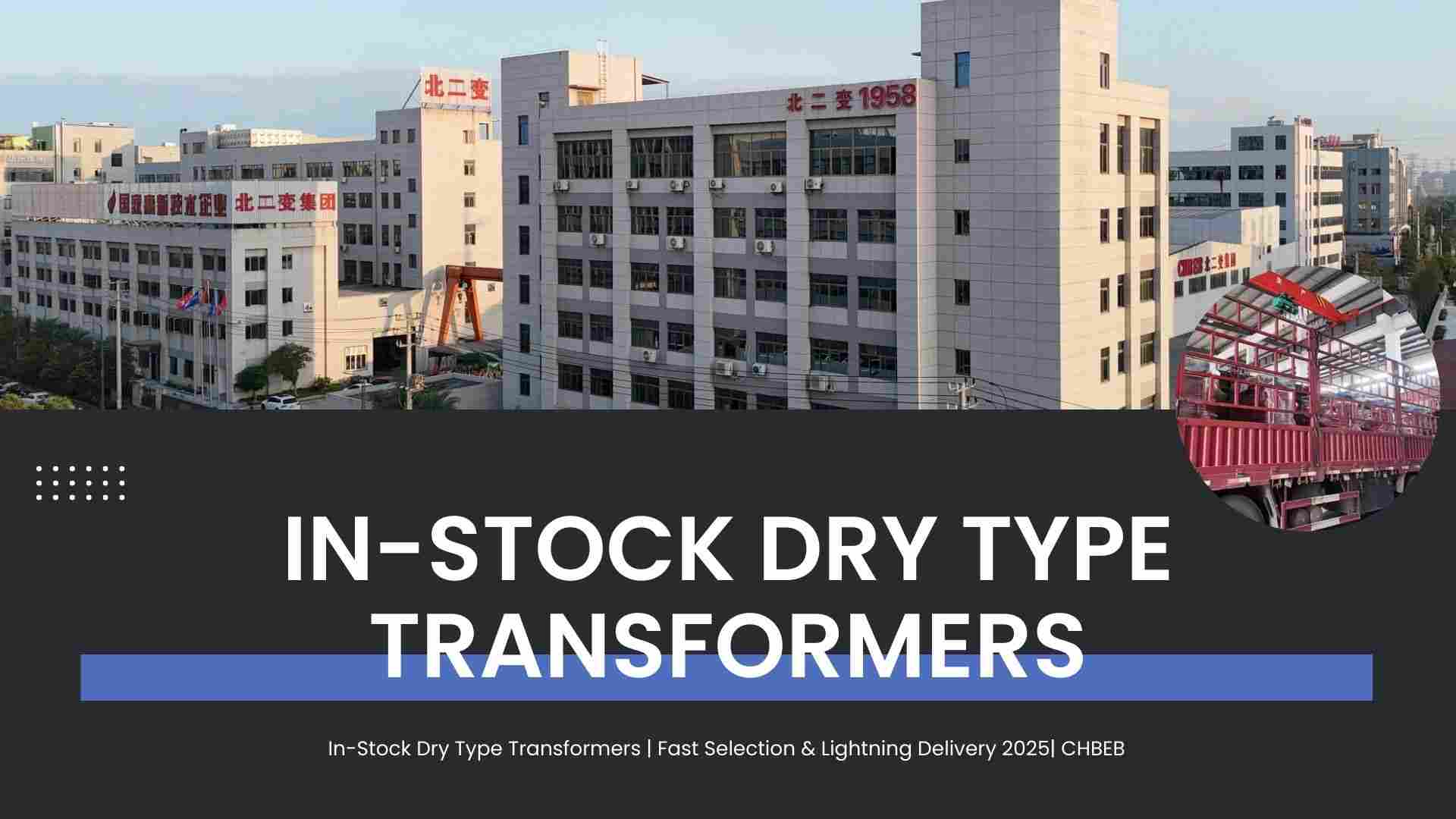
Need it right away? Your Guide to Dry Type Transformers in Stock, Quick Selection, and Fast Delivery
Introduction
It can take months to get custom builds, which isn’t good for transformer problems or urgent jobs. Delays imply lost time, money, and angry customers. The answer? Choose from our selection of in-stock dry type transformers1, which include models that are ready to ship and will arrive quickly to keep your project on track.
Fast Selection: Finding Your In-Stock Dry Type Transformer Model
Waiting for design and production when time is important might lead to expensive delays. The answer is to choose from units that are already in stock, have been tested, and are ready to be shipped. This way, you can get back to work or fulfill project deadlines without having to make any compromises.
In-Stock vs. Custom: Why You Should Choose In-Stock When You Need It Fast
- In Stock: Ready to ship right away, with standard ratings and pre-certification.
- Custom: Designs made just for you, but it takes 8 to 12 weeks.
- Best for when you need it: In-stock means no downtime, which is especially important for emergency replacements and fast-track projects.
In-Stock Model List: A Quick Look at Common Ratings & Specs
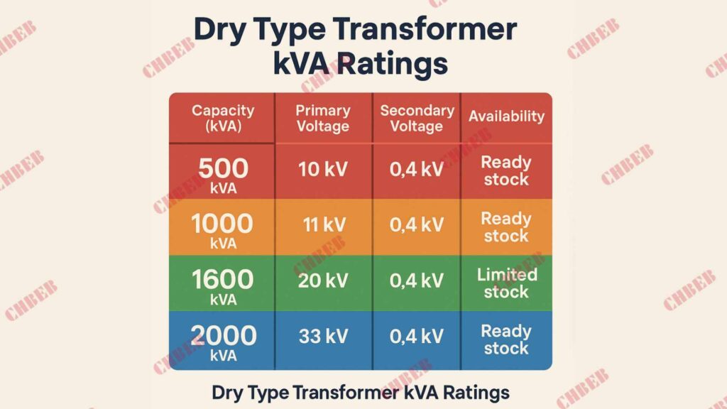
These are some examples of dry type transformer models that are often in stock:
| Capacity (kVA) | Primary Voltage | Secondary Voltage | Cooling | Availability |
|---|---|---|---|---|
| 500 kVA | 10 kV | 0.4 kV | AN/AF | Ready stock |
| 1000 kVA | 11 kV | 0.4 kV | AN/AF | Ready stock |
| 1600 kVA | 20 kV | 0.4 kV | AN/AF | Limited stock |
| 2000 kVA | 33 kV | 0.4 kV | AN/AF | Ready stock |
(Note: Models vary by area; check to see whether they are available in your area.)
The 3-Step Quick Selection Method: Make Your Needs Clear Now
- Identify Capacity: Make sure your kVA matches the load requirement with a safety buffer.
- Check Voltage: Make sure the primary and secondary ratings match the grid and the site.
- Check Availability: Call sales to make sure your reservation is confirmed before shipping.
Lightning-Fast Delivery: Our Nationwide Logistics Network & Service Promise
Reliable delivery is just as important as urgent supply. A lot of providers offer too much and don’t deliver. What do we do? A logistics network that works and gives you genuine timetables and guarantees from the manufacturer to your site.
Our Delivery Reach and Timeline: Nationwide Coverage
- Coverage: Warehouses are built near industrial centers for a reason.
- Timeline: Most in-stock goods will be shipped within 24 to 48 hours.
- Flexibility: You can choose between express road freight and air freight for projects that are far away.
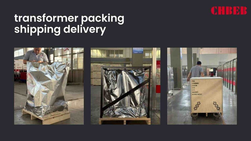
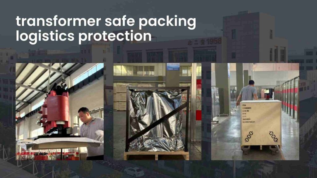
Guaranteed Safety: Full Logistics Protection from the Factory to Your Door
- Safe packing: shockproof, waterproof, and meets IEC transport regulations2.
- Insurance: Full coverage from the time you leave to the time you get there.
- Tracking: Get real-time information on your logistics so you know what’s going on.
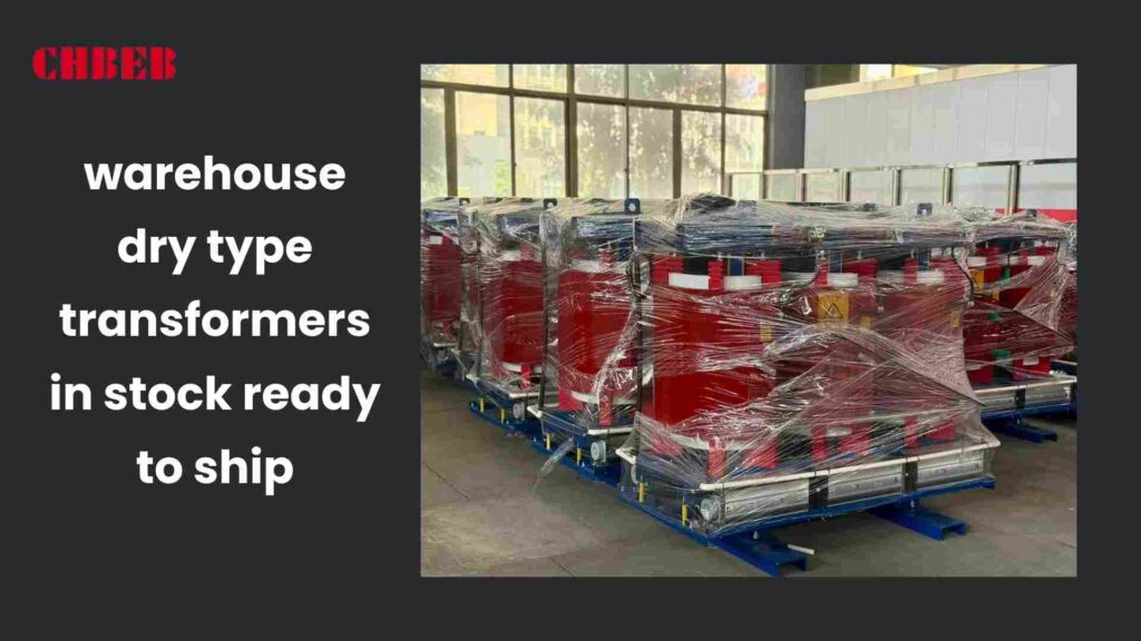
Quality Assurance: You can trust the products we have in stock
Quick delivery shouldn’t mean inferior quality. Some people who buy things worry because they are old or leftover. The answer is to strictly follow certifications, tests, and support after the sale.
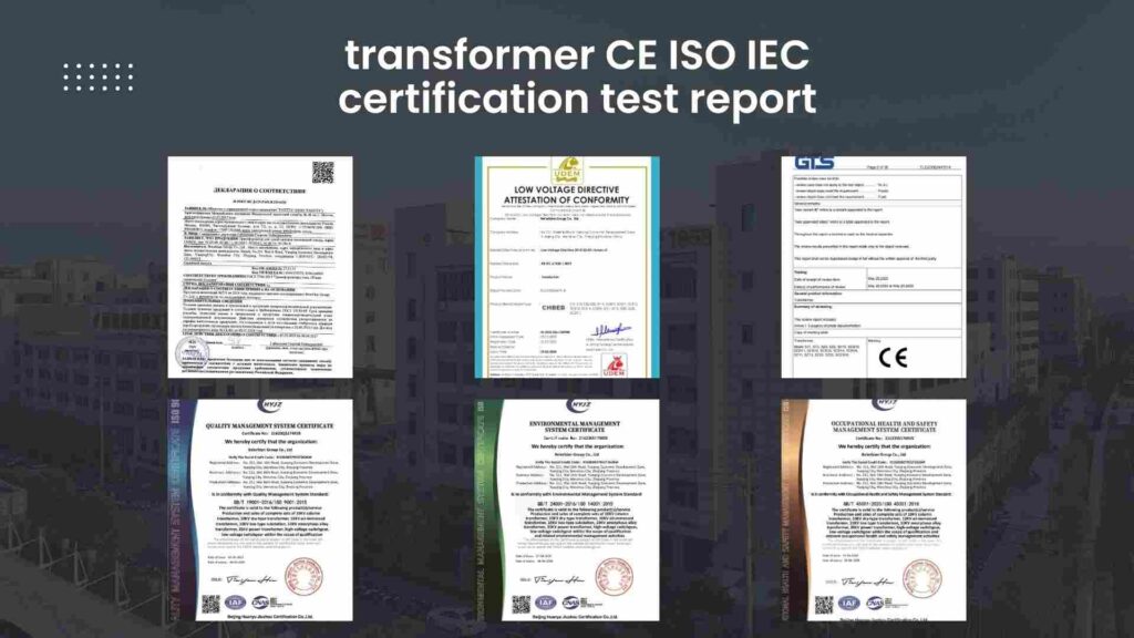
Strict Standards: Our Test Reports and Quality Certifications
- Certifications: CE, ISO90013, ISO14001, and IEC.
- Testing: Before storing, routine testing (insulation, ratio, load) were done.
- Reports: Each device comes with a test certificate.
Full After-Sales: Support for Your Purchase That You Don’t Have to Worry About
- Coverage for a standard 12 to 24 months.
- Technical Support: Engineers can help with problems from a distance or in person if needed.
- Spare Parts: Easy access to common spare parts to cut down on downtime.
Conclusion
The quickest and safest way to address urgent needs is with dry type transformers that are in stock. You can address problems and keep projects going without delay with quick model selection, shipping anywhere in the country, and high quality standards.
- Dry-Type Transformer Overview ↩︎
- International Transport & Packaging Standards ↩︎
- ISO 9001 & ISO 14001 Standards ↩︎
Learn More
Looking for the right dry-type transformer for your project? Download our latest product catalog or browse our product categories to find reliable solutions tailored to your needs.
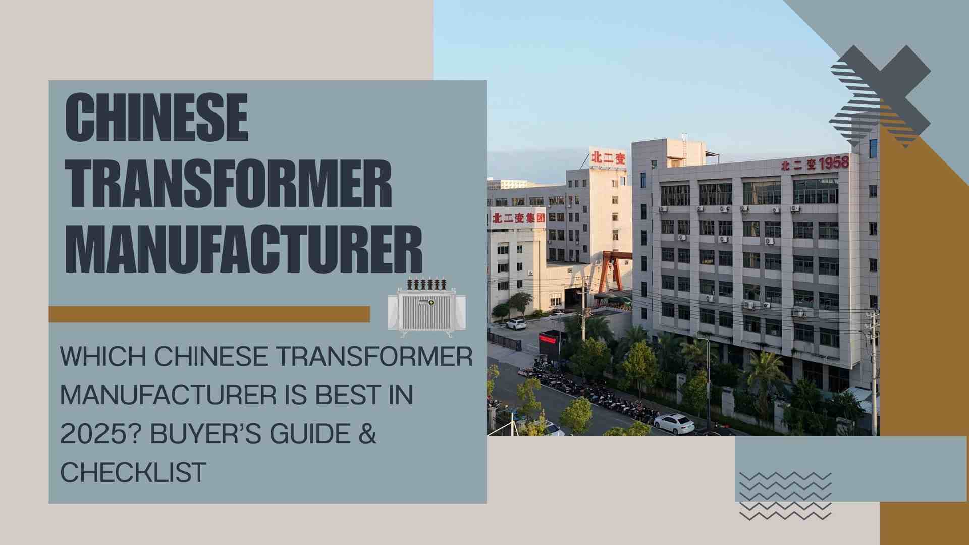
Introduction
In 2025, many global buyers will search for the best Chinese transformer manufacturer 2025, hoping to find one perfect choice. The reality? There is no universal best. Every project has unique technical, financial, and operational requirements. The smart approach is to evaluate transformer suppliers against your project’s specific needs—capacity, voltage, efficiency, certification, and budget.
Debunking the Myth: No Single “Best” Transformer Manufacturer
Believing one brand is always “best” often results in mismatched purchases and increased risks. Instead, clarify what “best” means for your situation. A supplier that excels in utility grid projects may not be the right choice for a data center or an industrial facility.
Defining “Best”: Start with Your Project Needs
Before you compare Chinese transformer manufacturers, define your own requirements:
- Voltage & Capacity: Distribution transformers and high-voltage power transformers follow very different design standards.
- Application: Utility grids, renewable energy plants, factories, mining, or data centers.
- Priorities: Is your focus on lowest upfront cost, maximum long-term efficiency, or fastest delivery?
Key Insight: The “best” Chinese transformer supplier is the one that meets your business and technical needs—not a one-size-fits-all solution.
Market Overview: Types of Chinese Transformer Manufacturers
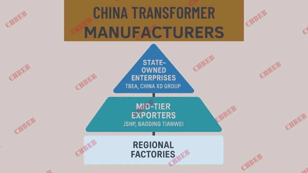
China’s transformer industry is broad, and understanding the positioning of suppliers helps buyers avoid missteps:
- State-Owned Enterprises (e.g., TBEA1, China XD Group2): Experts in ultra-high-voltage (UHV) and mega EPC projects.
- Mid-Tier Exporters (e.g., JSHP, Baoding Tianwei): Balance global certifications, reliability, and competitive pricing.
- Regional Factories: Offer low prices but often limited in advanced testing and after-sales service.
Result: Choose a supplier whose scale, quality systems, and experience match your project’s size and risk tolerance.
Evaluation and Vetting: Finding the Right Supplier
Hard Criteria: Technical Skills, Certifications & Track Record
- Capabilities: Can they deliver on kVA, voltage, loss levels, and cooling method (oil-immersed or dry-type)?
- Certifications: ISO9001, ISO14001, IEC, CE, or KEMA for international acceptance.
- References: Evidence of success in grid tenders, EPC contracts, or export projects to your region.
Soft Criteria: Service, Communication & Transparency
- After-Sales Support: Warranty terms, spare parts availability, and response times.
- Communication: Professional English support, clear documentation, fast feedback.
- Pricing Transparency: Itemized quotations, clear delivery terms, and guaranteed loss values.
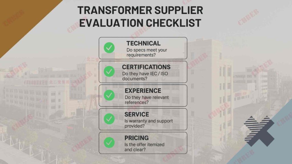
Supplier Evaluation Checklist
| Category | Key Questions | Red Flags |
|---|---|---|
| Technical | Do specs match kVA, voltage, and losses? | Vague or generic answers |
| Certifications | Are IEC/ISO documents valid and verifiable? | Fake or expired certificates |
| Experience | Do they have relevant project references? | No case studies or hidden clients |
| Service | Is warranty and spare parts included? | Avoids after-sales discussions |
| Pricing | Is the quote itemized and transparent? | Hidden costs or unclear scope |
International Procurement & Risk Mitigation
Without a clear roadmap, international sourcing can lead to hidden costs and delays. A structured process reduces these risks:
- Inquiry: Send an RFQ with detailed specifications (kVA, voltage, cooling, loss values, and standards).
- Evaluation: Compare technical offers, certifications, and pricing.
- Audit: Arrange third-party inspections or video audits before signing.
- Contract: Define delivery schedule, penalties, guaranteed losses, and payment terms.
- Production: Approve drawings and witness factory acceptance tests.
- Logistics: Confirm insurance, packaging, and customs documents.
- After-Sales: Secure warranty contacts and spare parts agreements.
Common Risks and Solutions
- Fake Certifications → Verify directly with issuing authorities.
- Hidden Costs → Request full, itemized quotes including logistics and accessories.
- Late Delivery → Add penalty clauses in the contract.
- Quality Problems → Hire SGS, TÜV, or trusted local inspectors before shipment.
Conclusion
Choosing a reliable Chinese transformer supplier is not about chasing one “best” brand. It is about finding the supplier that aligns with your project’s budget, technical requirements, compliance standards, and risk profile.
By applying a structured procurement process—defining specifications, verifying certifications, auditing production, and securing clear contracts—buyers can confidently source oil-immersed, dry-type, or low-loss transformers from China in 2025.
✅ Final takeaway: Stop searching for “the best” in general. Define what “best” means for your project, and select the supplier that matches those needs for long-term reliability and value.
Learn More
Looking for the right dry-type or oil-immersed transformer for your project? Download our latest product catalog or explore product categories to discover reliable, low-loss transformer solutions tailored to your requirements.

Introduction
If you choose the wrong transformer, you could end up with overloads, voltage drops, and expensive downtime. A lot of purchasers have trouble with kVA, starting variables, and picking the right materials. This guide goes over the basics so you can choose the right transformer size and design for your project.
Transformer Capacity Basics: What kVA and the Starting Factor Mean
People commonly mix up kVA and kW or forget how much power a motor needs to start. This causes units to be too small and to break down. Before making decisions about materials or costs, you need to know the basics of capacity.
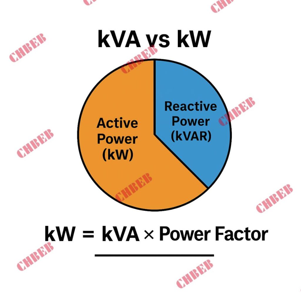
What do kVA and kW1 mean? Why do we rate transformers in kVA?
Transformers are rated in kVA (kilovolt-ampere) instead of kW since they give off both active power (kW) and reactive power (kVAR). Power factor (PF) determines how much power can be used.
- The formula for kW is kVA × PF.
- For instance, a 100 kVA transformer with a 0.8 PF gives forth 80 kW of real power.
Transformers are always rated in kVA since the power factor (PF) changes depending on the kind of load (motors, lighting, electronics).
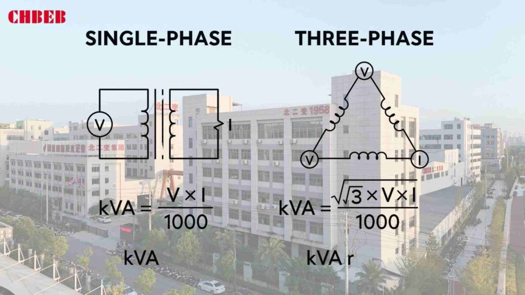
Formulas for calculating the kVA of a transformer (single-phase and three-phase)
If you don’t use formulas, you could end up with too big or too small of a size, which could be dangerous. The answer is to use the proper formula for each situation.
- Single-phase: kVA=V×I1000kVA = \frac{V × I}{1000}kVA=1000V×I Example: 240 V × 100 A = 24,000 VA = 24 kVA
- Three-phase: kVA=3×V×I1000kVA = \frac{\sqrt{3} × V × I}{1000}kVA=10003×V×I Example: 415 V × 100 A × 1.732 = 71,800 VA = 71.8 kVA
What is a factor that starts? How to Figure Out How Much kVA You Need to Start a Motor
Underrated designs break down when motors start up, when the inrush might be 4–7 times the entire load current. To figure out the kVA of a transformer, you need to use a beginning factor.
- kVAneeded = MotorHP × 0.746Efficiency × PF × Starting Factor kVA_{required} = Motor HP × 0.746{Efficiency × PF} × Starting FactorkVAneeded=Efficiency×PFMotorHP × 0.746 × Starting Factor
- For a reliable starter, a 75 HP motor with 0.9 efficiency, 0.85 PF, and 6× inrush needs a transformer with a capacity of about 440 kVA.
Case Study: How to Figure Out the Total Load and Transformer Capacity for an Industrial Workshop
A workshop has:
- 2 × 50 HP motors
- 1 × 30 HP motor
- Lighting load 20 kW
Step 1: Convert motor HP to kW
- 50 HP = 37.3 kW × 2 = 74.6 kW
- 30 HP = 22.4 kW
- Lighting = 20 kW
- Total = 117 kW
Step 2: Use PF (0.85) and Efficiency (0.9) 117 ÷ (0.85 × 0.9) = 153 kVA
Step 3: Add a starting factor for motors (with a safety margin of ×1.25)
Final transformer capacity needed is about 190 kVA.
Result: Pick a 200 kVA transformer to handle the starting and load g
Balancing Performance & Cost: Choosing Winding Material & Cooling Method
A lot of buyers pay too much for copper or don’t think about how much cooling they need. Both errors raise costs or shorten the life of the product. The best way to get the right balance is to look at winding and cooling simultaneously.
A Close Look at the Pros, Cons, and Costs of Copper and Aluminum Windings
- Windings of copper
- More conductivity means less loss.
- Smaller size, better in handling overloads
- More expensive at first
- Windings made of aluminum
- Less expensive, lighter
- Needs bigger cross-sections to match copper
- Losses that are a little higher
Comparison Table
| Factor | Copper | Aluminum |
|---|---|---|
| Conductivity | High | ~61% of copper |
| Size & Weight | Smaller, heavier density | Larger, lighter metal |
| Cost | Higher | Lower |
| Durability | Superior | Good with modern alloys |
| Best Fit | Critical/continuous loads | Cost-sensitive projects |
A Full Guide to Transformer Cooling: Natural vs. Forced, Dry-Type vs. Oil-Immersed
Mistakes in cooling might lead to overheating and insulation failure. The answer is to match the type of cooling to the conditions at the site.
- Dry-Type Transformers
- Air cooling (natural or forced)
- Safer indoors, higher cost, lower ratings
- Oil-Immersed Transformers
- Mineral oil or ester fluid
- Efficient cooling, outdoor use, fire precautions needed
Cooling Methods:
- ONAN stands for “Oil Natural Air Natural.”
- ONAF (Oil Natural Air Forced)
- Oil Directed Air Forced (ODAF)
- AN/AF (Air Natural/Air Forced for dry types)
How to Choose the Best Material and Cooling Method for Your Needs
Hospital or high-rise building inside? Pick the dry variety with copper windings.
Substation or renewable farm outside? Choose oil with aluminum in it (this is the cheapest option).
Heavy industry with burdens that don’t stop? Copper + oil for the best durability.
Ensuring Long-Term Reliability: Other Critical Selection Factors
A lot of purchasers only look at kVA and material. Not taking into account power factor, voltage, and the environment might cause early failures. The answer is to think about important details that were missed.
The Importance of Power Factor and How to Fix It
Bad PF equals wasted space and fines. Using capacitor banks or active filters to fix things makes transformers smaller, lowers losses, and makes the system work better.
Ambient Conditions, Voltage, and Losses: The Details That Are Often Missed When Choosing
- High temperatures necessitate derating.
- Altitude: More over 1000 m makes cooling less effective.
- Voltage Changes: Make sure the tap changer range meets the stability of the grid.
- Losses: Ask for guaranteed no-load/load losses; these add to the cost of energy over time.
Your FAQs and Transformer Selection Checklist
List of things to do:
- ✔ Figure out kVA (beginning factors included)
- ✔ Check PF and make any necessary changes
- ✔ Pick between aluminum and copper windings
- Choose cooling based on the conditions at the place.
- ✔ Think about the weather: the temperature, the height, and the humidity
- ✔ Look for IEC, ANSI, and GB certifications.
- ✔ Compare capital expenditures to operating expenses during the life of the project
Questions and Answers:
- Why do we rate transformers in kVA instead of kW? This is because they give both active and reactive power.
- Copper windings are cheaper than aluminum windings, but aluminum is bigger.
- Which lasts longer, dry type or oil immersed? With the right care, oil-immersed things usually endure longer.
Conclusion
Choosing the right transformer is not just about picking a size off the shelf—it requires a structured approach.
- Start with capacity: Calculate the kVA correctly, including motor starting factors, to prevent overloads and hidden downtime costs.
- Balance materials and cooling: Copper vs. aluminum windings2 and dry-type vs. oil-immersed designs should be chosen based on application, cost targets, and safety needs.
- Account for operating conditions: Power factor, temperature, altitude, and guaranteed loss values directly impact lifetime performance and energy costs.
- Think lifecycle, not just purchase price: Compare CAPEX with OPEX over 20–30 years to secure the best ROI.
✅ Final takeaway: The best transformer is the one that matches your kVA demand, starting profile, and site environment, while balancing safety, performance, and cost. A well-specified design ensures reliable operation and long-term savings.
Learn More
Looking for the right dry-type transformer for your project? Download our latest product catalog or browse our product categories to find reliable solutions tailored to your needs.
Introduction
Picking the wrong brand could mean lost time and money. China’s market is busy and moves quickly, which makes things even more confusing. With proven market drivers, objective brand profiles, and a useful decision framework, this book helps you limit down your options.
Part 1: The Market Landscape and Important Brand Profiles
An overview of the China Transformer Market and its main drivers in 2025
When planners neglect structural drivers, projects come to a halt. If you don’t spend enough in the grid and renewables, you can end up with old specs. The solution is to base choices on demand indications from 2025.
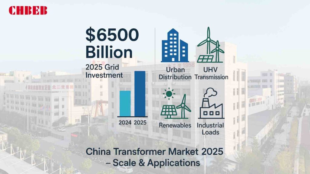
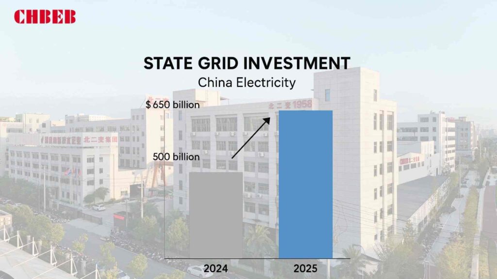
- State Grid1 aims to invest more than ¥650 billion (~$88.7 billion) in 2025 to improve transmission and distribution. This is after spending more in 2024. Reuters
- Explosive Renewables: In 2025, China installed more than 1,000 GW of solar power, which made the need for high-reliability grid and step-up transformers even greater. The Magazine for Transformers
- UHV Build-out: Ongoing UHV AC/DC corridors, including mixed-energy lines for new-energy bases, keep HV/EHV transformers in focus. People’s Daily
What it means: Specifications are moving toward fewer losses, greater ratings, digital monitoring, and being ready for UHV/HVDC.
Market Leaders: The Big Companies in the U.S. That Are Running National Projects
Choosing vendors that are too small can cause delays. If you don’t pay attention to national winners, you miss out on proven UHV capacity and auction victories. Solution: create a list of state-linked and big private leaders with proven scale.
- China XD2 Group is a state-owned company that makes transformers up to 1100 kV and has large research and development and testing labs. It is the main supplier for UHV/GRID projects.
- TBEA is a major player in UHV/HVDC and a supplier to the State Grid for both transmission and integrating renewables (a lot of people in the China market talk about them). Mordor Intelligence
- Baoding Tianwei Baobian Electric makes large-scale power and UHV AC/DC transformers. It is listed in Shanghai and has been in business for a long time in the >500 kV segments.
- JSHP Transformer is a major exporter of power transformers (up to hundreds of MVA) with a significant global presence and exports.
Why they are in the lead: their capacity, their experience with domestic projects, and their ability to bid on State Grid/CSG projects, which will continue in 2025. news.metal.com
Technology and the High-End Market: The Big Companies in China
If you think “foreign = always better,” you’re wasting money; if you don’t, you could lose efficiency over time. It’s important to find a balance.
- Siemens Energy offers high-end power and dry-type portfolios, as well as digital services. They are also still investing in transformer capacity.
- Hitachi Energy (previously ABB Power Grids) works with several partners in China to use HVDC/dry-type and eco-friendly technology.
- GE Vernova (Grid Solutions) is a company that makes grid equipment and transformers for renewable energy and transmission projects.
- Schneider Electric and Mitsubishi Electric are major players in the Chinese market, especially in distribution and industrial transformers and advanced protection and monitoring. Mordor Intelligence
When to choose: complicated renewables, digitalized plants, strict loss/footprint goals, or service needs that span many countries.
Part 2: Comparing and buying things in several ways
Core Competencies: A Look at Technology, Products, and Segments
Only looking at the price per unit raises the total cost over time. Look at how well the technology fits, the risk of delivery, and the service model.
| Dimension | Chinese Leaders (China XD, TBEA, BTW, JSHP) | International Leaders (Siemens Energy, Hitachi Energy, GE Vernova, etc.) |
|---|---|---|
| Voltage/Scale | Extensive HV/EHV, up to 1100 kV; UHV/HVDC pedigree via State Grid projects. 西电集团 | Broad global portfolio; strong at premium ratings and complex specs. siemens-energy.com |
| Tech Focus | Compliance-driven, robust designs; accelerating low-loss materials and digital add-ons. | Advanced monitoring, eco-fluids, dry-type innovation, HVDC expertise. hitachienergy.com |
| Delivery & Scale | Large local capacity, competitive lead times for grid-standard builds. | Longer scheduling for imported or high-customization units. |
| Pricing | Generally lower CAPEX; strong value for standardized specs. | Higher CAPEX; potential OPEX savings via losses/uptime. |
| References | UHV corridors, national tenders, massive domestic base. news.metal.com | Global flagship projects; strong multinational service networks. siemens-energy.com |
| Best Fit | State-backed infra, standard renewables, utility distribution. | High-spec renewables, industrials with strict LCC targets. |
Buyer’s Guide: How to Choose the Right Brand for Your Project
Redesigns that cost a lot of money happen when the scope and tender documentation aren’t clear. Not doing certification or service checks could cause downtime. Solution: a five-step selection process that takes losses into account.
- What is a scenario and risk tolerance (PAS ≤50 words): Incorrectly scoped voltage, cooling, or environment might add hidden costs over time. Tighten the use case: transmission, substation, plant GSU, or industrial distribution? Make sure you understand the ambient, harmonic profile, noise restrictions, footprint, and grid-code compliance.
- Lock down technical baselines
- Voltage/kVA and duty: GSU vs step-down; overload and backup profile.
- Loss classes: Set GB/IEC targets (like S20) that guarantee no-load/load loss and include penalty clauses.
- Fire safety and site restrictions; ONAN/ONAF/ODAF vs. dry-type; cooling and insulation.
- Standards and tests: IEC/GB, routine/type/special (for example, temperature rise, impulse, and sound).
- Map needs to brands
- Chinese officials want uniform grid builds, more exposure to UHV/HVDC, and speedier local delivery.
- When digitization, eco-fluids, or very low total losses drive payback, international leaders. siemens-energy.com
- Check the market momentum for 2025 (PAS ≤50 words): Old pipeline data messes up schedules. Check the capacity and tender activities, such State Grid’s record spending in 2025 and current UHV procurements, to figure out how much work suppliers have and how long it will take. Reuters
- Do a comparison of lifetime costs (LCC)
- Model the cost of energy for the next 25 to 30 years, together with the site’s tariff forecast.
- Include upkeep, spare parts, digital monitoring, and the chance of an outage.
- Look at the trade-offs between capital expenditures (capex) and kilowatt-hour (kW) loss. A more expensive unit can win on operating expenses (OPEX) in 3–7 years, which is what most industrial tariffs assume.
Checklist for due diligence
- References: Installations with similar duties from 2020 to 2025.
- Factory audits: winding, cutting the core, vacuum drying, and FAT capabilities.
- ISO 9001/14001, IEC type test reports, and GB conformity are all examples of certificates.
- Contracts: Loss assurances with penalties and local service available.
Conclusion
China’s transformer market in 2025 combines scale, speed, and innovation. The choice is no longer just between domestic and international names, but between cost-efficient capacity and premium technology with long-term payback.
Domestic leaders (China XD, TBEA, Baoding Tianwei, JSHP) remain the first choice for UHV/HVDC corridor projects, rapid delivery, and standardized grid builds. They bring proven State Grid references, cost competitiveness, and strong local scale.
International giants (Siemens Energy, Hitachi Energy, GE Vernova, Schneider, Mitsubishi) deliver eco-fluids, digital monitoring, and premium loss profiles, making them ideal for complex renewable integration, multi-country operations, and projects with strict lifecycle cost (LCC) targets.
👉 How to decide:
Map your scenario and risk tolerance: transmission, substation, GSU, or industrial distribution.
Lock down technical baselines: voltage/kVA, loss class, cooling method, and compliance standards.
Compare lifecycle costs (CAPEX + OPEX + downtime risk), not just upfront price.
Verify suppliers with recent references, certificates, and service coverage.
✅ Final takeaway: The best brand is not the biggest logo, but the one that aligns with your technical duty, delivery certainty, and 25-year cost model. In 2025, winners will be those who balance grid-scale capacity with digital reliability.
Learn More
Looking for the right dry-type transformer for your project? Download our latest product catalog or browse our product categories to find reliable solutions tailored to your needs.
Introduction
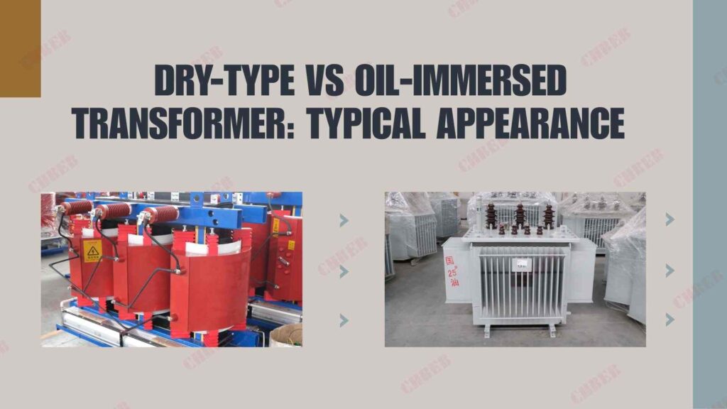
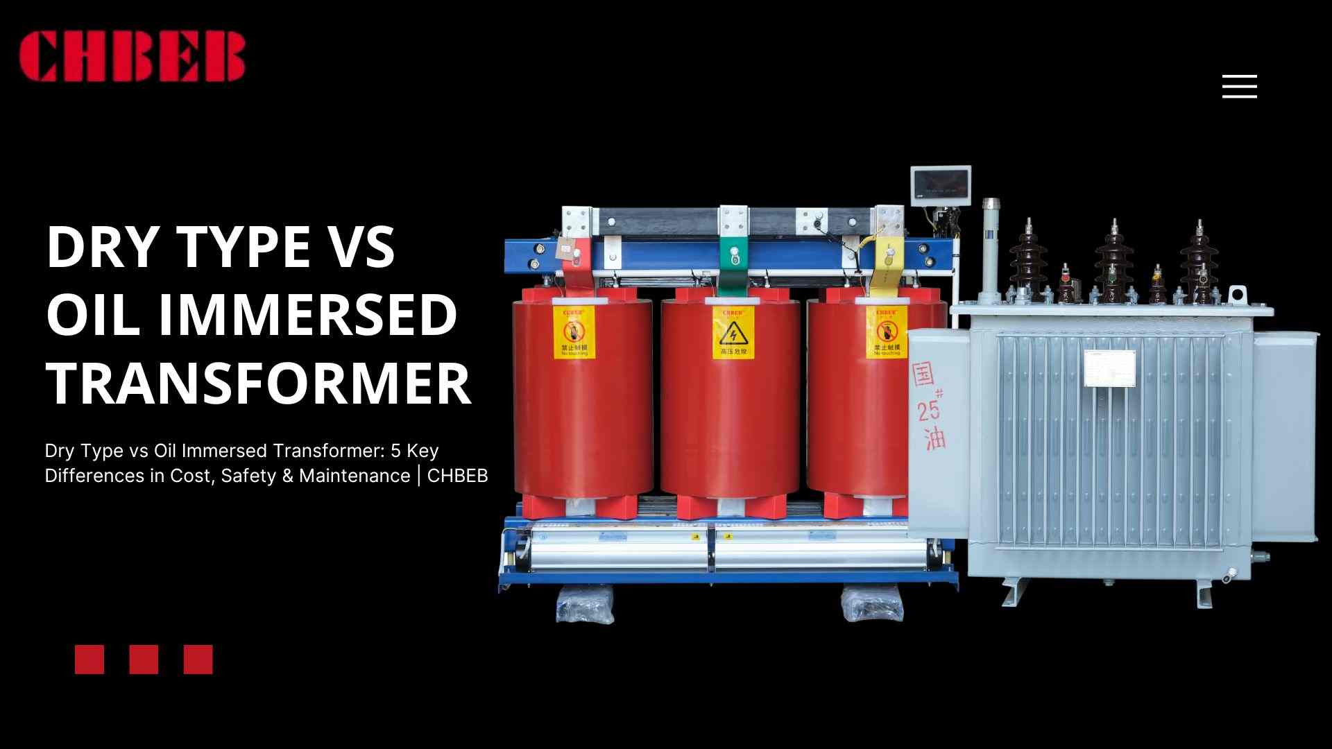
If you pick the wrong transformer, you could have to pay a lot of money for downtime, safety issues, and maintenance problems. A lot of buyers have trouble figuring out which type is best for their project. This guide explains the distinctions between dry type and oil-immersed transformers1 so you can make a confident choice.
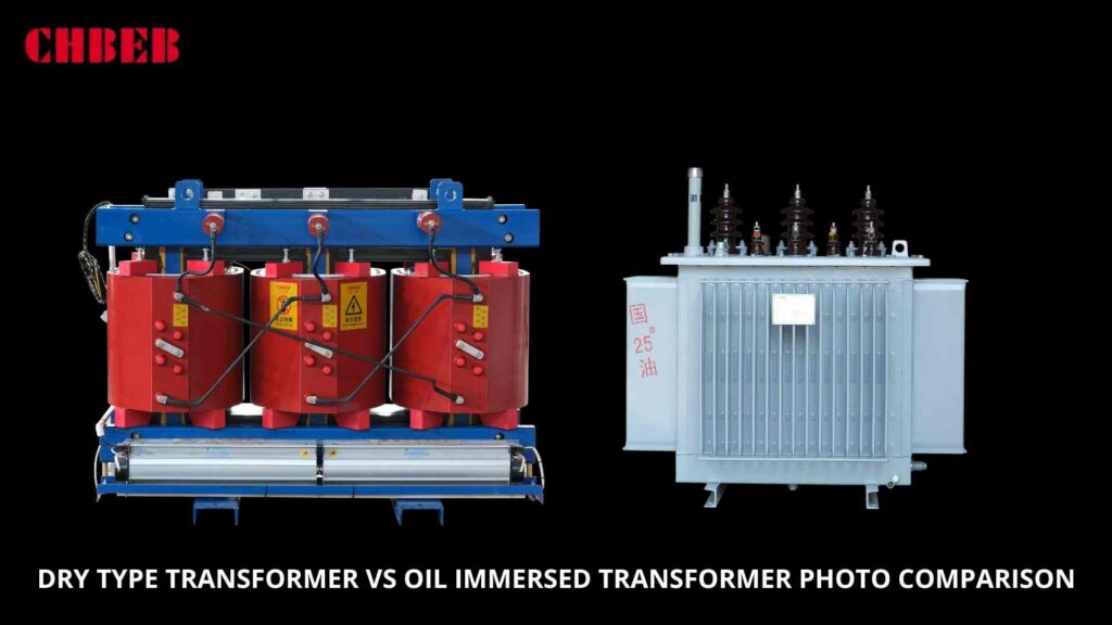
The Main Difference: How They Function
Transformers may seem the same, but the way they deal with heat and insulation is what sets them apart. If you don’t grasp this, things can go wrong, accidents can happen, or things can break down too soon. Let’s go into the main rules for how it works.
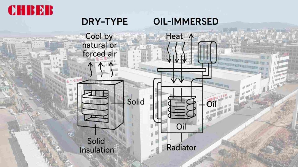
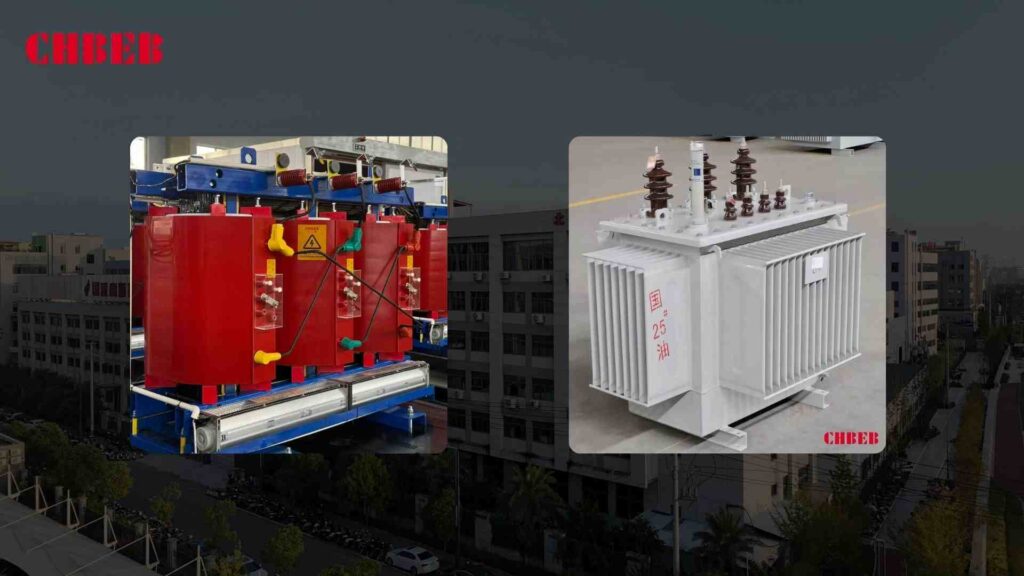
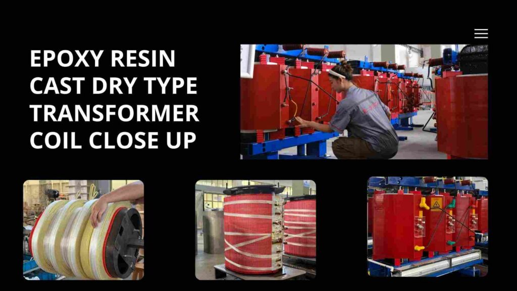
Dry-Type Transformers: Depend on Solid and Air
Instead of liquid, dry-type transformers use air and solid insulation materials.
- Cooling: either by natural means or by forced air.
- Epoxy resin, pressboard, or composite materials are used for insulation.
- Main Benefits: Less chance of fire, less harm to the environment, and can be used indoors.
- Normal Uses: schools, hospitals, commercial buildings, and interior substations.
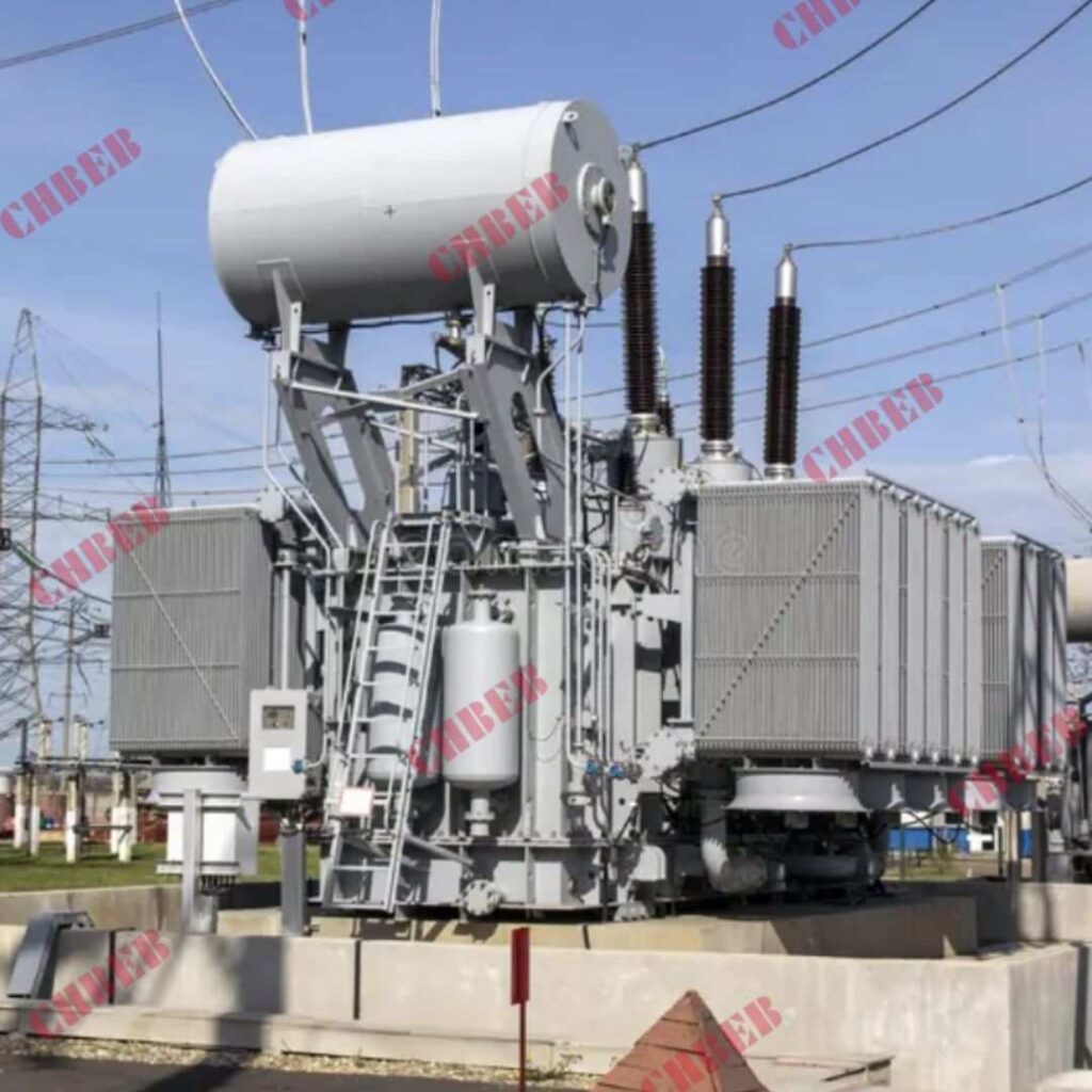
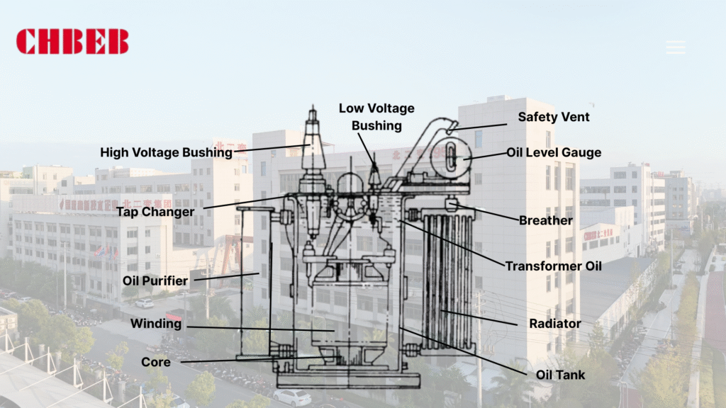
The Role of Dielectric Fluid in Oil-Immersed Transformers
Mineral or synthetic oil is used to insulate and cool oil-immersed transformers.
- Cooling: Oil takes in heat and moves it to radiators or coolers.
- Insulation: Oil makes dielectric strength stronger and stops electrical arcs.
- Key Benefits: Can handle heavier loads and lasts longer when used heavily.
- Common Uses: Substations in the open air, industrial plants, and utility-scale distribution.
The 5 Key Differences: A Side-by-Side Comparison
Picking the improper type can have an impact on safety, cost, and performance. Here is a full comparison of the five most important things.
1. Safety and Effects on the Environment
Accidents with electricity or oil leaks might be quite bad.
| Feature | Dry-Type | Oil-Immersed |
|---|---|---|
| Fire Risk | Low (no flammable liquid) | Higher (oil is flammable) |
| Environmental Impact | Minimal, non-toxic | Oil spills can contaminate soil/water |
| Indoor Suitability | Ideal | Requires special precautions |
Dry-type transformers work well in small or sensitive spaces, while oil-immersed units need to be kept safe from fire and other hazards.
2. Cost: Initial Investment vs. Total Cost of Ownership (TCO)2
The price you pay to buy it is only part of the story.
- Dry-Type: Higher initial cost per kVA, but reduced insurance and maintenance costs.
- Oil-Immersed: Costs less up front, but costs more to maintain, test oil, and clean up spills.
Tip: Don’t simply look at the sticker price; think about the total cost of ownership (TCO), which includes things like energy losses, maintenance, and longevity.
3. Upkeep and Longevity
The complexity of maintenance can have an impact on downtime and costs of doing business.
| Feature | Dry-Type | Oil-Immersed |
|---|---|---|
| Routine Maintenance | Minimal (dust removal, visual checks) | Frequent (oil testing, leak checks, cooling system inspection) |
| Lifespan | 20–30 years | 25–40 years with proper care |
| Downtime Risk | Lower | Higher if leaks or faults occur |
If you don’t want to have to do much work on them, dry-type transformers are a good choice. Transformers that are immersed in oil need extra care, but they work well even when there is a lot of weight on them.
4.Load Capacity and Efficiency
Efficiency affects how much it costs to run and how much energy is wasted.
- Dry-Type: Usually has a lower load capacity and may lose a little more power when fully loaded.
- Oil-Immersed: Handles more weight and cools better; works better for big or industrial uses.
Tip: Pick based on what you need to carry. Oil-immersed versions are frequently better for big industrial applications.
5.Putting it together and using it
The installation environment decides what is practical.
| Feature | Dry-Type | Oil-Immersed |
|---|---|---|
| Indoor Use | Excellent | Needs safety measures and containment |
| Outdoor Use | Limited, requires enclosures | Ideal for outdoor substations |
| Space Requirements | Compact | Larger footprint due to cooling equipment |
| Noise | Quiet | Moderate, may need sound reduction |
Transformers that are dry-type work well indoors with little chance of fire, whereas oil-immersed transformers are best for heavy-duty outside use.
Making the Right Choice: A Summary Guide
Choosing the correct transformer will keep you safe, make sure it works, and save you money.
When to Choose Dry-Type:
- Installation within schools, hospitals, or businesses
- Having a low risk of fire is very important.
- It is best if there is little maintenance.
- Environmental sensitivity is a worry
When to Choose Oil-Immersed:
- For use outside or in factories
- You require a lot of load capacity.
- Long longevity under heavy use is needed
- There is extra money in the budget for safety and upkeep.
Conclusion
Dry-type and oil-immersed transformers each have unique strengths, and the right choice depends on your project’s safety requirements, budget, and operating environment.
- Choose a Dry-Type Transformer if your installation is indoors, in sensitive locations such as hospitals, schools, or commercial buildings, where fire safety, low maintenance, and environmental protection are top priorities.
- Choose an Oil-Immersed Transformer if your application demands high load capacity, long service life under heavy operation, and outdoor suitability, such as in substations, industrial facilities, or utility-scale distribution networks.
When evaluating, don’t stop at the purchase price. Consider the Total Cost of Ownership (TCO), including energy efficiency, downtime risks, and ongoing maintenance. A well-matched transformer not only ensures safe and reliable operation, but also maximizes your ROI by reducing long-term costs and improving system performance.
👉 Final tip: Align your transformer choice with your installation environment, load requirements, and risk tolerance. This structured approach will help you avoid costly mistakes and secure a solution that is both efficient and sustainable.
- Oil-Immersed Transformer: Construction, Working and Applications ↩︎
- Transformer Total Cost of Ownership ↩︎
Learn More
Looking for the right dry-type transformer for your project? Download our latest product catalog or browse our product categories to find reliable solutions tailored to your needs.
Introduction
You shouldn’t have to guess how much a transformer will cost. Prices are hard to pin down because materials, requirements, and lead times change. This guide makes the prices of 2025 dry-type transformers obvious by turning them into tables and steps. This will help you plan correctly and buy with confidence.
2025 Dry-Type Transformer Price Guide: Cost by kVA Ratings
When you skip capacity, voltage, or safety adders, you get sticker shock. To avoid underbids and change orders, you should know the price ranges and what is included.
What is the price of a dry-type transformer per kVA?
Assumptions: three-phase, 50/60 Hz, standard indoor installation, normal impedance, IEC/IEEE compliance, ex-works (no freight, tax, or extras). VPI is about the same as the baseline, but cast resin costs more.
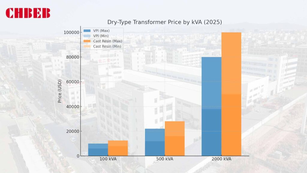
| Rating | Typical HV/LV (kV) | VPI Price Range (USD) | Cast-Resin1 Price Range (USD) | Approx. $/kVA (VPI) | Typical Use Cases |
|---|---|---|---|---|---|
| 100 kVA | 6–11 / 0.4 | $6,000–$10,000 | $8,000–$12,500 | $60–$100 | Shops, small offices, light commercial |
| 500 kVA | 6–15 / 0.4–0.69 | $12,000–$22,000 | $16,000–$28,000 | $24–$44 | Campuses, retail hubs, small factories |
| 2000 kVA | 11–24 / 0.4–0.69 | $38,000–$80,000 | $50,000–$100,000 | $19–$40 | Hospitals, metro stations, larger plants |
- Cast-resin premium: usually 15–30% more than VPI at the same rating.
- For a higher voltage class (22–35 kV), add 8–20% for BIL, insulation, and clearances.
- Low-loss cores (amorphous/Hi-B): add 10–15% up front and cut no-load losses.
The VPI standard spec says that for every kVA: 100 kVA: $60–$100/kVA; 500 kVA: $24–$44/kVA; 2000 kVA: $19–$40/kVA. Higher ratings lower the price per kVA.
What Will Cause the Prices of Dry-Type Transformers to Change in 2025?
Small design choices add up rapidly. Add prices early to stop the budget from going up.
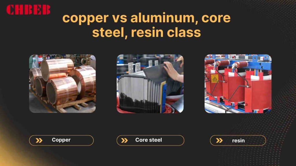
- Copper is more expensive and has fewer losses, while aluminum is less expensive and has a bigger cross-section.
- Core steel: High-grade grain-oriented or amorphous cores cut down on losses when there is no load, but they also raise the cost per unit.
- Class F/H, low-smoke/halogen-free resins, and humidity protection add to the cost of the insulation system.
- Fans (AF), RTDs, relays, thermal scanners, and Modbus/IEC 61850 gateways add 3 to 15% for cooling and monitoring.
- Acoustics and enclosure: Filters and coatings that make designs quieter and raise IP/NEMA ratings by 5–20%.
- Compliance and testing: IEC/IEEE routine and type tests, UL/CE markings, witness FAT, and paperwork all take time and money.
- Freight, customs, and foreign exchange rates can change the price of goods by 5% to 25%.
- Lead time: Quotes can go up a lot because to rush premiums and backlog cycles.
Total Cost of Ownership (TCO)2: More than the Price Tag
It can cost more later to buy an inexpensive unit. Energy losses and downtime are sometimes much bigger than tiny capex reductions. Don’t simply look at the quote; look at the lifetime cost.
Why efficiency is important for the long-term costs of transformers
Every hour, there are losses. No-load runs all the time, and load losses go up with current and harmonics. Saving a few kilowatts can save you a lot of money over your lifetime.
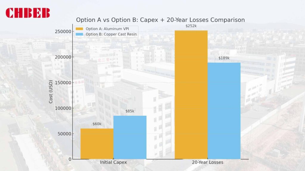
A simplistic example:
- Option A: 2000 kVA, Aluminum VPI: Buy for $60,000; lose about 12 kW.
- Option B: 2000 kVA, Copper Cast-Resin: Buy for $85,000; losses are about 9 kW.
Let’s say $0.12 per kilowatt-hour, 8,760 hours per year, and 20 years.
A: 12 × 8,760 × $0.12 = $12,614 every year, which is $252,000 over 20 years.
B: 9 × 8,760 × $0.12 = around $9,460 a year, or $189,000 over 20 years.
Energy delta: B saved almost $63,000, which helped make up for the increased capital expenditures, not including the thermal margin, uptime, and resale value.
- Make loss assurances in the PO stricter (with penalties for going over).
- Think about harmonics (drives/EV). It may be necessary to use a K-factor or derating.
- Check the ambient temperature, altitude, and duty cycle; these all affect the rise in temperature and the life of the device.
How to Get a Formal Quote for a Transformer in 2025
When specifications are unclear, quotes change. Give a clear brief to generate numbers that are similar and can be defended.
- kVA and duty: continuous rating, overloads, and temperature/altitude.
- Voltage and taps: LV/HV, vector group, tap range/steps (off-load/OLTC).
- Technology: VPI or cast resin; conductor made of copper or aluminum.
- Loss targets: no-load/load losses are assured, and there is a punishment schedule.
- Class (e.g., 80K/100K), natural/forced air, and fan phases for temperature rising and cooling.
- Enclosure and IP/NEMA: for indoor and outdoor use, with filters and coatings for coastal and corrosive environments.
- Sound: maximum dB(A) at a certain distance; site limitations.
- Compliance: IEC/IEEE editions, UL/CE, routine/type tests, and witness FAT.
- Monitoring: RTDs, relays, and communications (Modbus, IEC 61850, and BACnet).
- Logistics: making crates, finding lifting points, setting footprint limitations, and delivery windows.
- Commercials: warranty, service SLAs, spare parts, training, and references.
Tip: Ask vendors to provide you a price for a baseline and a low-loss option next to each other. Then compare the cost of capital plus 10/20 years of energy.
Conclusion
The cost of a dry-type transformer in 2025 depends mainly on its kVA rating, voltage level, and design choices (e.g., insulation system, core materials, technology). Using benchmarks such as 100 / 500 / 2000 kVA helps set realistic budgets, while accounting for adders like higher voltage class, low-loss cores, and enclosure/IP requirements prevents surprises later.
Looking beyond the sticker price is essential. By evaluating the Total Cost of Ownership (TCO)—including energy losses, maintenance, and downtime—buyers can identify options that save more over the service life of the unit.
A clear and accurate RFQ, backed by firm loss guarantees and compliance checks (IEC/IEEE, UL/CE where applicable), remains the best way to secure a transformer that is reliable, efficient, and cost-effective for decades of operation.
Learn More
Want to explore more transformer solutions? Download our latest product catalog or browse our product categories to find the right transformer for your project.
Introduction
It’s hard to figure out how to budget for dry-type transformers. Prices change based on the materials and demand, and suppliers give varying quotes. One mistake leads to spending too much and delays. This guide makes it easier to understand 2025 prices, drivers, and supplier strategy so you can make a choice with confidence.
Dry-Type Transformer Price Landscape in 2025: Key Drivers
When transformer costs go up more than expected, projects collapse. Quotes are affected by materials, technology, and following the rules. You can prevent hidden costs and make accurate budgets if you know price ranges and drivers.
How Much Does a Dry-Type Transformer Cost by kVA in 2025?
The price changes the most based on the voltage class and capacity (kVA). The ranges below are for typical three-phase systems that are shipped directly from the factory. Shipping, taxes, testing, and installation are not included.
| kVA Rating | HV Range | VPI Price (USD) | Cast-Resin1 Price (USD) | Typical Uses |
|---|---|---|---|---|
| 50–200 | 6–11 kV | $4,000–$12,000 | $6,000–$15,000 | Shops, small offices |
| 250–500 | 6–15 kV | $9,000–$22,000 | $12,000–$28,000 | Campuses, retail |
| 750–1,000 | 10–20 kV | $18,000–$40,000 | $24,000–$55,000 | Factories, mid-size plants |
| 1,250–2,000 | 11–24 kV | $32,000–$75,000 | $42,000–$95,000 | Hospitals, metro stations |
| 2,500–3,150 | 11–33 kV | $60,000–$125,000 | $80,000–$160,000 | Industrial feeders |
| 4,000–5,000 | 13.8–35 kV | $110,000–$220,000 | $145,000–$290,000 | Utilities, heavy industry |
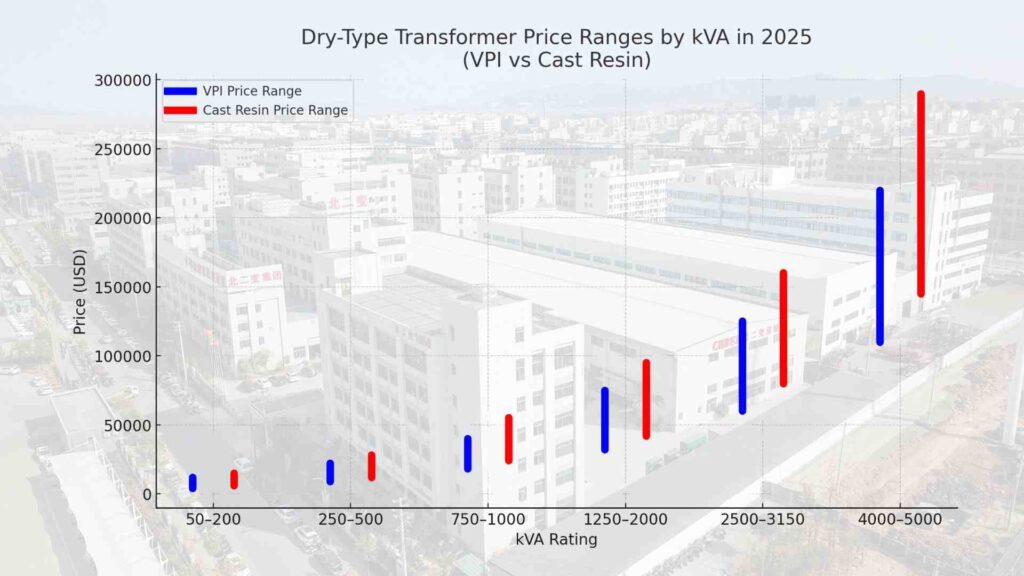
- Impact of technology: Cast-resin usually costs 15–30% more than VPI because of the fire safety and epoxy casting.
- Voltage effect: When you move up to 22–35 kV, the strength and clearances of the insulation normally get up by 8–20%.
- Regional differences: North America tends to be higher (UL/CSA), whereas Asia tends to be lower (localized supply chains).
What Will Affect the Prices of Dry-Type Transformers in 2025?
Small design changes might quickly change the pricing. Knowing these things stops budget shocks from happening.
- Copper is a better conductor than aluminum because it makes things work better and can handle short circuits better (around 20–40% more expensive).
- Quality of core steel: Grain-oriented or amorphous cores cut no-load losses by 10–15% of capital expenses.
- Insulation and resin: Higher-class (like Class H) and low-smoke resins make things safer and more expensive.
- Accessories like RTDs, temp relays, forced-air blowers, heaters, and sound kits add about 5–25%.
- Compliance testing: IEC/IEEE type tests, UL/CE, and FAT documents take more time and money.
- Freight and tariffs: Ocean freight, import fees, cranes, and permissions can change the price by 10% to 25%.
- Lead time and FX: Quotes are affected by rush orders and currency changes. Longer lead times usually get better prices.
For example, a 1,000 kVA cast-resin unit in Europe may cost $45,000 ex-works, but shipping, customs, and FAT testing can make the total cost more than $60,000.
Total Cost of Ownership (TCO) and a Guide for Suppliers
A low price up front can be a trap. Over the course of 20 years, losses, downtime, and insufficient support cost more. Calculating TCO and checking out suppliers helps keep lifetime value.
What is the real total cost of ownership (TCO) for dry-type transformers?
TCO = Purchase Price + Installation + Energy Losses + Maintenance + Downtime − Residual Value
- Energy losses: No-load runs all the time; load losses go up with current and harmonics.
- Lower than oil-filled, however fans, RTDs, and windings need to be checked on a regular basis.
- Risk of downtime: One outage in a hospital or metro can cost more than the purchase price.
- Residual value: Premium items that are fully certified keep their resale value.
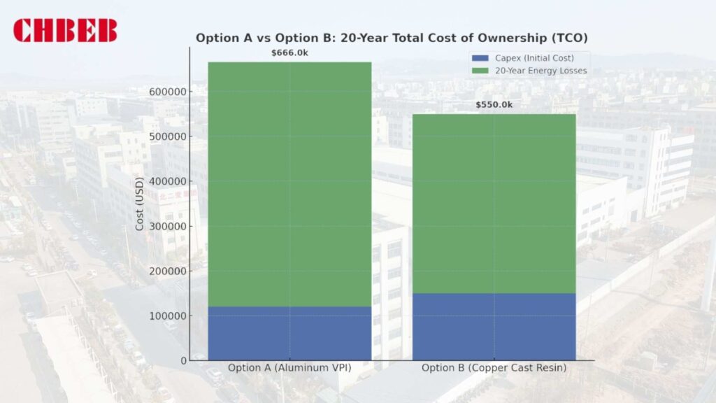
For example, Option A (Aluminum VPI) costs $120,000 and loses around 12 kW, while Option B (Copper Cast-Resin) costs $150,000 and loses about 9 kW. Option B saves over $140,000 in energy over 20 years at $0.12 per kilowatt-hour, which more than makes up for the $30,000 disparity in capital expenditures..
Don’t buy based on sticker price; lifetime cost is more important than losses.
How to Pick the Best Dry-Type Transformer Supplier in 2025
A bad supplier can cause delays, extra expenditures, and problems with compliance. Match your strengths to your risk profile and your timetable.
- Global giants like Hitachi Energy, Siemens, and Schneider have proven technology, good documentation, and spare parts available all over the world. However, they cost more and take longer to get.
- Regional champions (Eaton, Toshiba, TBEA): faster delivery, knowledge of local codes, and prices that are comparable. Check the depth of QA.
- OEM/ODM experts (Daelim, niche makers): make custom builds for small spaces, low noise, and tough sites; check factories and ask for type-test results with FAT witness choices.
Checklist for suppliers:
- IEC/IEEE compliance with routine and type test reports; UL/CE as needed
- Guaranteed no-load and load losses with penalty clauses
- Temperature rising class, cooling stages, and control of hot spots
- Noise level guaranteed at a certain distance (in cities)
- Terms of warranty, service SLAs, replacement parts and training in your area
- Look at projects with the same kVA/voltage and surroundings.
Warning signs: confusing drawings, missing test data, “equivalent” exchanges after the purchase order, ambiguous warranties, and pressure for big prepayments.
Put loss assurances in the contract as a practical recommendation. Small discrepancies in no-load can add up to tens of thousands over the term of the contract.
Conclusion
In 2025, the cost of a dry-type transformer is driven mainly by kVA rating, voltage level, materials/technology (e.g., copper vs2. aluminum; VPI vs. cast-resin), and compliance requirements (IEC/IEEE, UL/CE). Looking only at the sticker price can be misleading—lower upfront cost may mean higher energy losses, more downtime, and unexpected maintenance over the life of the unit.
For engineers & technical buyers
Evaluate the Total Cost of Ownership (TCO): Purchase + Installation + Energy Losses + Maintenance + Downtime − Residual Value. Higher-efficiency designs (e.g., copper windings or cast-resin insulation) can reduce losses and often save six-figure amounts on energy over a 20-year horizon.
For project owners & procurement managers
- Don’t compare on price alone—request type/routine test reports and ensure IEC/IEEE compliance.
- Ask for guaranteed losses with penalty clauses and clear warranty/service terms.
- Consider lead time, documentation quality, and after-sales support as part of value.
By looking beyond initial quotes and focusing on long-term performance, you’ll secure a transformer that is safe, efficient, and cost-effective. Partnering directly with a source factory like CHBEB can combine competitive pricing with faster delivery and international-standard quality, giving you confidence from specification to commissioning.
- Cast Resin Transformers — All About Circuits ↩︎
- Copper vs. Aluminum in Transformer Windings — ScienceDirect ↩︎
Learn More
Want to explore more transformer solutions? Download our latest product catalog or browse our product categories to find the right transformer for your project.
Introduction
Prices seem to change all the time, and one false guess might ruin your budget. Next come delays and gaps in compliance. This tutorial talks about the costs of dry-type transformers in 2025, what causes them, and how to pick vendors that will give you long-term value.
Price Trends and Main Factors Affecting Dry-Type Transformers in 2025
Sticker prices change according on metals, shipping, and requirements. If you don’t pay attention to this, bids will miss the mark. Know how kVA, voltage, materials, and tariffs impact quotations so budgets meet market conditions.
What is the price of a dry-type transformer based on kVA and voltage?
Wide price ranges (in USD) for typical three-phase VPI or cast-resin systems. Shipping, taxes, extras, testing, and installation are not included.
| kVA Class (3-phase) | Typical LV/HV (kV) | VPI Price Range | Cast-Resin Price Range | Notes |
|---|---|---|---|---|
| 50–200 kVA | 0.4 / 6–11 | $4,000–$12,000 | $6,000–$15,000 | Small commercial; indoor |
| 250–500 kVA | 0.4 / 6–15 | $9,000–$22,000 | $12,000–$28,000 | Campuses, retail, light industry |
| 750–1,000 kVA | 0.4–0.69 / 10–20 | $18,000–$40,000 | $24,000–$55,000 | Data room adjacency, small plants |
| 1,250–2,000 kVA | 0.4–0.69 / 11–24 | $32,000–$75,000 | $42,000–$95,000 | Hospitals, metro, factories |
| 2,500–3,150 kVA | 0.69 / 11–33 | $60,000–$125,000 | $80,000–$160,000 | Large commercial/industrial |
| 4,000–5,000 kVA | 0.69 / 13.8–35 | $110,000–$220,000 | $145,000–$290,000 | Utility tie-ins, heavy industry |
- When the voltage changes from about 11–15 kV to about 22–35 kV, the BIL, insulation, and clearances frequently go up by 8–20%.
- Effect of technology: Cast-resin usually costs 15–30% more than VPI at the same grade.
What factors affect price, such as materials, tariffs, and market forces?
- Copper conductors cost more1 to make and lose less energy; aluminum conductors cost less to make and have a bigger cross-section.
- Core steel: High-grade GO/amorphous lowers no-load losses but costs more.
- Insulation/resin: Class F/H, low-smoke standards make it more expensive.
- IP/NEMA enclosures, RTDs, relays, heaters, and sound kits add 3% to 20% to the price.
- Compliance and testing: IEC/IEEE type tests, UL/CE, and witness FAT take more time and money.
- Tariffs and freight: Duties, ocean and air fees, cranes and licenses can change the cost of delivery by 5% to 25%.
- FX and lead time: Changes in currency and rush fees effect quotes.
How to Pick a Reliable Supplier and the Total Cost of Ownership
Buying based on the sticker price doesn’t work. A low quote can be far less than the cost of downtime, maintenance, and losses. To make sure you get reliable service and savings, use TCO and supplier checks.
What is the real TCO of a dry-type transformer2, not just the price?
TCO = Purchase + Logistics/Install + Energy Losses + Maintenance + Downtime − Residual Value
- Energy losses: No-load runs all the time; load losses go up with current and harmonics.
- Cleaning, checking the fans and relays, and doing IR scans are all part of maintenance. It’s not as low as oil-filled, but it’s not zero either.
- Unplanned outages or derating often cost the most time.
- Residual value: Quality units with all the paperwork keep their resale worth.
For example:
- Option A (Aluminum/VPI): $120,000; 8 kW with no load; 18 kW with load loss at 50% average load.
- Option B (Copper/Cast): $150,000; 6 kW with no load; 14 kW with 50% average load.
- Power costs $0.12 per kilowatt-hour and lasts for 20 years, or 8,760 hours a year.
A losses about 12.5 kW, which is about $27.3k per year or $546k over 20 years. B losses are about 9.5 kW, which is about $20,000 a year or $400,000 over 20 years. B saves around $146,000 on energy, which makes up for the $30,000 increase in capital expenditures.
Which suppliers will provide you the best deal in 2025?
There isn’t one “best” fit for everyone. Match the strengths of the provider to the application, the risk, and the timetable.
- Global leaders: Deep engineering, good documentation, and a network of spare parts; more capital spending and longer lead times.
- Regional champions: quick delivery, knowledge of local codes, and low prices; check QA and traceability.
- OEM/ODM experts: tight footprints, low noise, harsh-site builds; check factories, go over type-tests, and see FAT.
Checklist for doing due diligence on a supplier:
- IEC/IEEE compliance, routine/type test reports, and UL/CE as needed
- No-load/load losses are guaranteed, however there are penalties.
- Temperature rising class, fan phases, and hotspot control
- Noise level is guaranteed at a certain distance.
- Rating for enclosures, filters, and coatings for coastal and corrosive sites
- RTDs, relays, and Modbus/IEC 61850 gateways for monitoring
- Crating, preparations for lifts and rigs, access issues, and lead time
- Terms of the warranty, service SLAs, spare parts package, and training
- Similar kVA/voltage and surroundings are used as references.
Red flags: drawings that aren’t clear, no loss caps, “equivalent” exchanges after the PO, missing serial test data, and terms for prepayment that are too forceful.
Conclusion
The cost of a dry-type transformer in 2025 is influenced by multiple factors: kVA rating, voltage level, materials, and compliance requirements. Looking only at the purchase price risks overlooking hidden costs that appear later in the lifecycle.
To make the right choice, buyers should go beyond initial Capex and carefully evaluate the Total Cost of Ownership (TCO). This includes energy losses over decades of operation, maintenance needs, potential downtime, and eventual residual value.
A structured approach makes the difference: define your technical requirements clearly, request transparent loss guarantees, and ensure that all equipment complies with IEC/IEEE standards. This not only prevents delays and budget overruns but also secures long-term safety and efficiency.
In short, matching transformer specifications to project conditions—whether in commercial buildings, industrial facilities, or renewable energy projects— is the key to achieving reliable performance and cost control throughout the transformer’s service life.
- Copper vs. Aluminum in Transformer Windings — ScienceDirect ↩︎
- Transformer Total Cost of Ownership — IEEE Xplore ↩︎
Learn More
Want to explore more transformer solutions? Download our latest product catalog or browse our product categories to find the right transformer for your project.
