Unveiling the Science of Electromagnetic Induction: The Secret Conversion of Electrical and Magnetic Energy
Introduction
Power doesn’t just happen; it has to be made. Generators and transformers work because changing magnetic fields make voltage and current. This guide makes things clear by explaining how induction works and how engineers make it work better.
The Scientific Foundation: History, Definition, and Core Laws
When magnetism and electricity seem abstract, things get confusing. It gets worse when we can’t “see” fields. The solution is a simple frame: induction happens when the magnetic flux varies, which is controlled by Faraday and directed by Lenz.
Concept Overview: What is Electromagnetic Induction? (The Key is a Changing Field)
When a magnetic flux changes via a conductor loop, it creates an electromotive force (EMF). This is called electromagnetic induction. The change, not the magnetism itself, makes electrons move.
E = − dΦ/d1t, where E is the induced EMF and Φ is the magnetic flux (Webers). This is how motors, generators, and transformers work.
Governing Principles: A Simple Explanation of Faraday’s and Lenz’s Laws
- Faraday’s Law: The amount of induced EMF is equal to the rate at which the magnetic flux through the circuit changes.
- Lenz’s Law says that the direction of the induced current goes against the change that caused it, which keeps energy from being wasted.
Together, they show why moving magnets, changing currents, or rotating coils can make electricity that can be used—there is no perpetual motion, simply conversion.
Real-World Power: The Two Pillars of Induction Technology
Until it turns a turbine or powers a metropolis, theory seems far away. Induction is made possible by two things: generators that create electricity and transformers that change the voltage.
Energy Pillar 1: The Generator—How Mechanical Motion Becomes Electricity
When you turn coils inside a magnetic field (or the field around coils), the flux varies all the time, which causes voltage to build up each time. Higher EMF comes from faster rotation and stronger fields.
| Type | Energy Input | Electrical Output | Typical Uses |
|---|---|---|---|
| AC Generator (Alternator) | Turbine rotation (steam, gas, hydro, wind) | Alternating current (AC) | Utility power stations, wind farms |
| DC Generator | Mechanical rotation + commutator | Direct current (DC) | Legacy DC systems, special drives |
Faraday’s principle in action: mechanical power changes the flux, which causes an EMF.
Energy Pillar 2: The Transformer—Voltage Scaling and the AC/DC Limitation
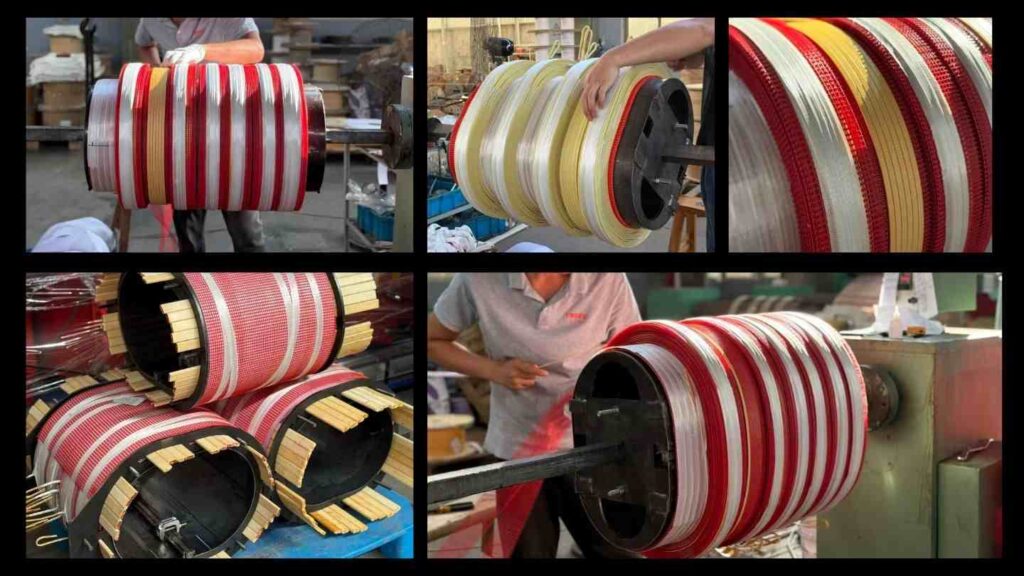
A transformer employs alternating current (AC) in the main coil to generate a magnetic field that changes over time in a common core. This causes voltage to flow in the secondary coil.
Ideal Relation: V₁ / V₂ = N₁ / N₂. The step-up or step-down factor is determined by the turns ratio2.
Why only AC? Flux stays constant under direct current (DC), so no electromotive force (EMF) is induced. That’s why AC is the primary form of electricity for long-distance transmission and local distribution.
👉 Learn more: Dry vs Oil Transformer Comparison
Engineering Challenges: Losses, Efficiency, and Modern Optimization
Real cores and conductors lose energy as heat and sound. Those losses make things less efficient and shorter. Engineers use materials, geometry, and process control to make them as small as possible.
Efficiency Barriers: Understanding and Minimizing Eddy Current and Hysteresis Losses
| Loss Type | What Causes It | Impact | Modern Mitigation |
|---|---|---|---|
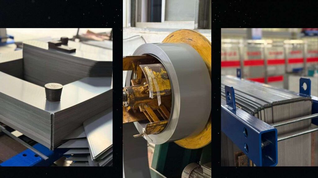
| Eddy Current Loss | Circulating currents in conductive cores under changing flux | Heat, lower efficiency | Laminated grain-oriented silicon steel; thin sheets; insulation coatings |
| Hysteresis Loss | Energy to realign magnetic domains each cycle | Heat during reversals | Low-loss steel grades; optimized flux density; proper frequency selection |
| Copper (I²R) Loss | Conductor resistance in windings | Thermal stress, efficiency drop | High-conductivity copper/aluminum; larger cross-section; lower temperature rise |
| Stray & Structural Loss | Leakage flux, vibration, imperfect geometry | Noise, hot spots | Finite-element design, bracing, VPI, careful layout |
Design levers include core material selection, lamination thickness, turns-per-volt, flux density, cooling method, and manufacturing precision (cut quality, step-lap joints, VPI).
👉 Learn more: Transformer Core Materials Guide · Transformer Maintenance Checklist
CHBEB — Reliable Partner for Distribution Transformers
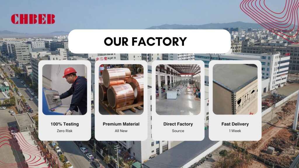
With over 60 years of transformer manufacturing expertise, CHBEB has become one of China’s most trusted distribution transformer suppliers. The company operates two factories in Wenzhou, one in Nanjing, and an office in Beijing, ensuring both strong production capacity and responsive customer support.
What makes CHBEB stand out:
- Strict Quality Commitment: All raw materials are 100% new and high-grade — no recycled or downgraded components.
- Proven Reliability: A qualified supplier for the State Grid Corporation of China, with a spotless record of zero major accidents.
- 100% Product Testing: Every unit is fully tested before delivery to guarantee safety, efficiency, and long service life.
- Fast-Track Orders: Ability to fulfill urgent orders in as little as one week, helping customers meet tight project deadlines.
- Custom Inventory Planning: Flexible stocking and supply strategies designed to align with customer procurement schedules.
- Global Outlook: Rooted in China and expanding worldwide, CHBEB actively supports local agents and partners, including assistance with market-specific certifications.
- Flexible Customization: Tailored transformer designs for utilities, contractors, and industrial clients, with reliable quality and fast delivery.
👉 Looking for a distribution transformer manufacturer that combines Chinese manufacturing strength with international standards?Contact CHBEB for a tailored solution or Download our full transformer catalog here.
📽️ Watch how CHBEB transformers are designed, assembled, and tested to meet IEC 60076 and global standards.
Conclusion
Electromagnetic induction is more than theory — it’s the foundation of every reliable transformer and power system. Understanding how changing magnetic flux creates voltage helps engineers and buyers recognize what truly defines performance: low loss, high efficiency, and long service life.
By selecting the right core materials, optimizing winding design, and managing eddy and hysteresis losses, projects can achieve measurable energy savings and stable grid operation over decades.
If you’re planning a new distribution or renewable energy project and want to improve efficiency, cost stability, and transformer reliability, our engineering team at CHBEB can help you apply these principles in practical designs built to IEC 60076 standards.
