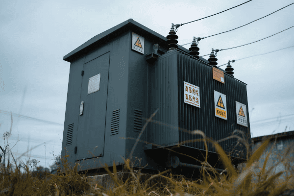
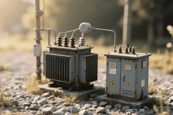
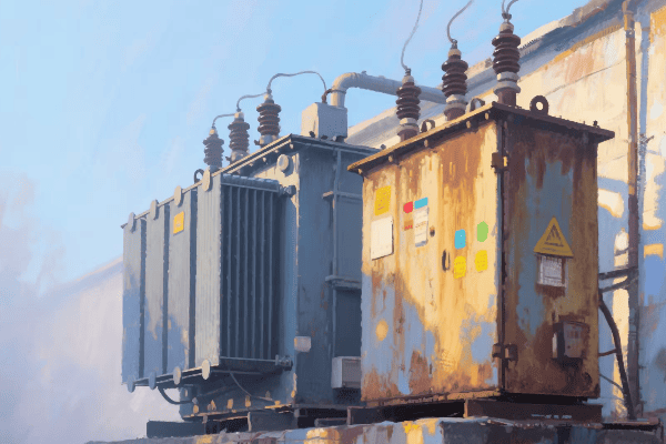
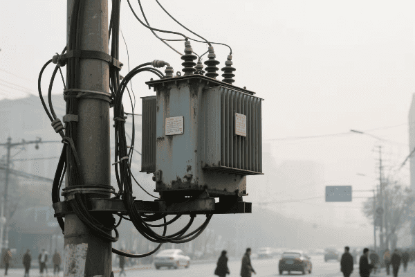
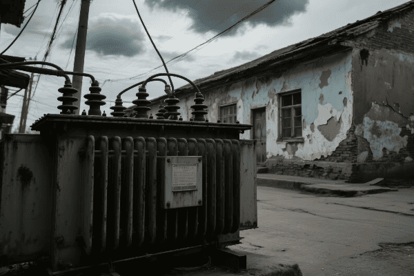
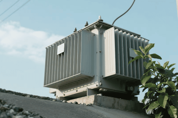
Have you ever wondered how electricity reaches your home safely and efficiently? The answer lies in a crucial piece of equipment: the 3 phase pad mounted transformer.
3 phase pad mounted transformers are key components in modern power distribution systems. They convert high voltage electricity to lower, usable voltages for homes and businesses. These transformers are compact, safe, and efficient, making them ideal for urban and suburban areas.

In this article, I’ll share my insights on 3 phase pad mounted transformers. My experience in designing and working with these transformers has shown me their critical role in our power infrastructure.
What Are the Unique Features and Advantages of 3 Phase Pad Mounted Transformers in Power Distribution?
When I first encountered a 3 phase pad mounted transformer, I was struck by its compact design and versatility. These transformers have revolutionized power distribution in urban areas.
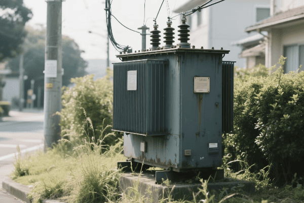
3 phase pad mounted transformers offer several unique features and advantages. They are compact, aesthetically pleasing, and provide easy access for maintenance. Their enclosed design enhances safety, while their three-phase configuration allows for efficient power distribution to both residential and commercial customers.
Let’s dive deeper into these features and advantages:
Compact and Aesthetically Pleasing Design
The design of these transformers is a game-changer:
- Space-Saving: They require less space compared to pole-mounted transformers.
- Low Profile: Their height is typically less than 6 feet, reducing visual impact.
- Customizable Appearance: They can be painted or enclosed to blend with surroundings.
I once worked on a project in a historic district where we had to design a pad mounted transformer that looked like a garden shed. It was a challenge, but the result was both functional and visually appealing.
Enhanced Safety Features
Safety is a top priority in these transformers:
| Feature | Benefit |
|---|---|
| Enclosed Design | Prevents unauthorized access and protects from weather |
| Lockable Compartments | Separates high and low voltage sections for added safety |
| Dead-Front Construction | Eliminates exposed live parts, reducing risk of accidental contact |
In my career, I’ve seen how these safety features have significantly reduced accidents and improved worker safety during maintenance.
Easy Maintenance Access
Maintenance is much simpler with these transformers:
- Front and Side Panel Access: Allows easy reach to components.
- Removable Doors: Facilitates replacement of large components.
- Ground-Level Installation: Eliminates need for bucket trucks or climbing.
I remember a project where we retrofitted an old substation with pad mounted transformers. The maintenance team was thrilled with how much easier and safer their job became.
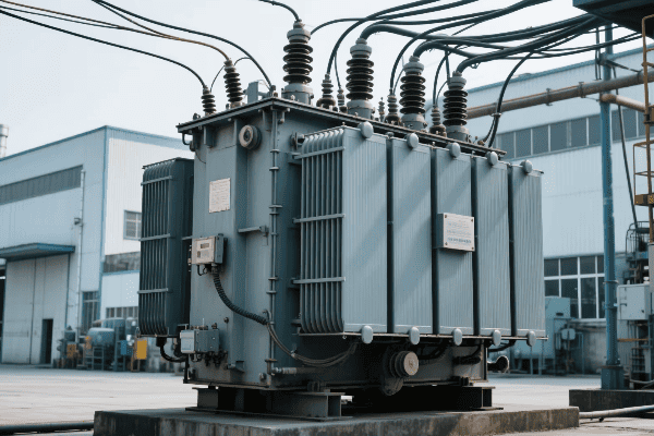
Three-Phase Configuration
The three-phase design offers several advantages:
- Balanced Load Distribution: Ideal for both residential and commercial areas.
- Higher Efficiency: Better power factor and reduced losses.
- Versatility: Can supply both single-phase and three-phase loads.
In a recent industrial park project, the three-phase configuration allowed us to efficiently power a mix of residential, commercial, and light industrial loads from the same transformer.
Environmental Considerations
These transformers are environmentally friendly:
- Oil Containment: Built-in features to prevent oil leaks.
- Reduced Noise: Quieter operation compared to pole-mounted transformers.
- Eco-Friendly Options: Some models use biodegradable fluids.
I’ve worked on projects where using eco-friendly insulating fluids was a key requirement. It’s amazing how far transformer technology has come in terms of environmental responsibility.
How Do 3 Phase Pad Mounted Transformers Enhance Efficiency and Reliability in Modern Grid Systems?
Efficiency and reliability are crucial in power distribution. I’ve seen firsthand how 3 phase pad mounted transformers have improved these aspects in modern grid systems.
3 phase pad mounted transformers enhance efficiency through reduced line losses and improved power factor. They increase reliability by providing better protection against outages and easier integration with smart grid technologies. Their design also allows for quicker repairs and replacements, minimizing downtime.
Let’s explore how these transformers boost efficiency and reliability:
Reduced Line Losses
Line losses are a significant concern in power distribution:
- Shorter Secondary Lines: Pad mounted transformers can be placed closer to loads.
- Lower Current: Three-phase configuration allows for lower currents at the same power.
- Improved Insulation: Modern materials reduce electrical losses.
I once worked on a project where replacing old pole-mounted transformers with pad mounted units reduced line losses by almost 15%. The energy savings were substantial.
Improved Power Factor
Power factor improvement is a key advantage:
| Aspect | Benefit |
|---|---|
| Balanced Loads | Three-phase design naturally balances loads |
| Reduced Reactive Power | Less strain on the distribution system |
| Better Voltage Regulation | Stable voltage leads to more efficient power use |
In a recent commercial district upgrade, the improved power factor from pad mounted transformers allowed us to defer a costly substation upgrade.
Enhanced Protection Features
These transformers come with advanced protection:
- Integrated Fusing: Protects against overloads and short circuits.
- Surge Arresters: Built-in protection against voltage spikes.
- Thermal Monitoring: Prevents overheating and extends transformer life.
I remember a case where the integrated protection in a pad mounted transformer prevented a major outage during a severe thunderstorm. It isolated the fault quickly, minimizing the impact.
Smart Grid Integration
Pad mounted transformers are ideal for smart grid integration:
- Sensor Integration: Easy to add monitoring devices.
- Communication Capabilities: Can be equipped with data transmission features.
- Remote Operation: Some models allow for remote switching and control.
I’ve been involved in several smart grid projects where pad mounted transformers were key to implementing advanced monitoring and control systems.
Quicker Repairs and Replacements
The design of these transformers facilitates faster maintenance:
- Modular Components: Easier to replace specific parts.
- Standardized Designs: Simplifies stocking of spare parts.
- Accessible Location: No need for specialized equipment for most repairs.
In my experience, the time to repair or replace a pad mounted transformer is often less than half that of a traditional pole-mounted unit. This significantly improves grid reliability.
What Are the Key Design Elements and Safety Considerations for 3 Phase Pad Mounted Transformers?
Designing 3 phase pad mounted transformers requires careful consideration of both functionality and safety. I’ve spent years refining these designs to meet evolving industry standards and customer needs.
Key design elements of 3 phase pad mounted transformers include compartmentalized construction, robust insulation systems, and efficient cooling mechanisms. Safety considerations encompass tamper-resistant enclosures, internal arc containment, and proper grounding. These features ensure safe operation and maintenance in public areas.

Let’s delve into the crucial design elements and safety considerations:
Compartmentalized Construction
The internal layout is critical:
- High Voltage Compartment: Isolated section for incoming lines.
- Low Voltage Compartment: Separate area for outgoing distribution.
- Transformer Section: Houses the core and windings.
I once redesigned a transformer layout to improve compartmentalization. This change significantly enhanced safety for maintenance workers and reduced the risk of accidental contact with high voltage components.
Insulation Systems
Proper insulation is vital:
| Component | Insulation Type | Purpose |
|---|---|---|
| Windings | Oil or Dry-Type | Prevents short circuits |
| Bushings | Porcelain or Polymer | Safely conducts current through the enclosure |
| Core | Oil or Air | Provides cooling and insulation |
In a recent project, we experimented with biodegradable insulating fluids. The results were promising, offering both excellent insulation properties and environmental benefits.
Cooling Mechanisms
Effective cooling is essential for longevity:
- Oil-Filled Designs: Use natural convection or forced oil cooling.
- Dry-Type Units: Employ air natural or forced air cooling.
- Hybrid Systems: Combine different cooling methods for optimal performance.
I’ve worked on developing cooling systems for transformers in extreme climates. In one case, we designed a custom cooling solution for a transformer in a desert environment, ensuring reliable operation in temperatures exceeding 50°C.
Tamper-Resistant Enclosures
Security is a top priority:
- Padlocked Doors: Prevent unauthorized access.
- Tamper-Proof Bolts: Secure access panels.
- Warning Labels: Clearly indicate dangers of entry.
I recall a project where we had to design extra secure enclosures for transformers in a high-crime area. The solution involved reinforced panels and advanced locking mechanisms.
Internal Arc Containment
Protecting against internal faults is crucial:
- Pressure Relief Devices: Safely vent internal pressure during faults.
- Reinforced Tank Design: Contains potential explosions.
- Arc-Resistant Doors: Prevent ejection of hot gases and oil.
I once witnessed a demonstration of arc containment features. The transformer contained a simulated internal fault without any external damage, showcasing the effectiveness of these safety measures.
Proper Grounding
Grounding is fundamental for safety:
- Equipment Grounding: Ensures all metal parts are at earth potential.
- System Grounding: Provides a return path for fault currents.
- Lightning Protection: Includes surge arresters and proper grounding.
In my experience, proper grounding is often overlooked but is critical for safety. I’ve seen cases where inadequate grounding led to dangerous touch potentials during fault conditions.
How Are 3 Phase Pad Mounted Transformers Integrated with Smart Grid Technologies?
The integration of 3 phase pad mounted transformers with smart grid technologies is revolutionizing power distribution. I’ve been at the forefront of this integration, witnessing the transformation of traditional grids into intelligent, responsive systems.
3 phase pad mounted transformers are integrated with smart grid technologies through advanced monitoring systems, communication capabilities, and automated control features. This integration enables real-time data collection, remote management, and improved grid responsiveness, enhancing overall efficiency and reliability.

Let’s explore how these transformers are becoming key components of smart grids:
Advanced Monitoring Systems
Modern transformers are equipped with sophisticated monitoring:
- Temperature Sensors: Track winding and oil temperatures.
- Load Monitoring: Real-time tracking of power flow.
- Dissolved Gas Analysis (DGA): Detect potential internal faults.
I recently worked on a project where we retrofitted existing pad mounted transformers with advanced monitoring systems. The utility gained unprecedented visibility into their distribution network’s performance.
Communication Capabilities
Communication is key in smart grids:
| Feature | Benefit |
|---|---|
| Wireless Connectivity | Allows remote data transmission |
| Ethernet Ports | Enables integration with utility networks |
| Protocols (e.g., DNP3, IEC 61850) | Standardizes communication across devices |
In one smart grid project, we implemented a mesh network of pad mounted transformers. This allowed for robust, self-healing communication even if individual links failed.
Automated Control Features
Automation enhances grid responsiveness:
- Remote Tap Changing: Adjust voltage levels without manual intervention.
- Fault Isolation: Automatically isolate faulty sections of the grid.
- Load Balancing: Dynamically adjust power flow for optimal distribution.
I’ve seen how these automated features can significantly reduce outage times. In one case, a smart transformer isolated a fault and rerouted power in less than a minute, minimizing the impact on customers.
Data Analytics Integration
Smart transformers generate valuable data:
- Predictive Maintenance: Use data trends to forecast potential issues.
- Load Forecasting: Analyze usage patterns for better resource planning.
- Power Quality Analysis: Identify and address power quality issues proactively.
I’ve been involved in developing analytics platforms that process data from hundreds of smart transformers. The insights gained have led to more efficient grid operations and reduced maintenance costs.
Renewable Energy Integration
These transformers play a crucial role in integrating renewables:
- Bi-Directional Power Flow: Handle power from distributed generation sources.
- Voltage Regulation: Maintain stable voltage with variable renewable inputs.
- Energy Storage Interface: Coordinate with battery systems for load balancing.
In a recent project, we designed a network of smart pad mounted transformers to manage a neighborhood with high solar panel penetration. The system successfully balanced the variable solar input with grid demand.
What Maintenance Practices and Monitoring Techniques Ensure Optimal Performance of 3 Phase Pad Mounted Transformers?
Maintaining 3 phase pad mounted transformers is crucial for their longevity and performance. Over the years, I’ve developed and implemented various maintenance strategies to keep these vital components running efficiently.
Optimal performance of 3 phase pad mounted transformers is ensured through regular inspections, proactive maintenance, and advanced monitoring techniques. Key practices include oil analysis, thermal imaging, partial discharge monitoring, and periodic electrical testing. These methods help detect potential issues early and prevent unexpected failures.
Let’s dive into the essential maintenance practices and monitoring techniques:
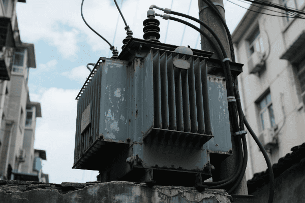
Regular Visual Inspections
Visual checks are the first line of defense:
- External Condition: Check for rust, dents, or leaks.
- Bushing Integrity: Inspect for cracks or contamination.
- Oil Levels: Verify proper oil levels in sight glasses.
I once discovered a small oil leak during a routine inspection that, if left unchecked, could have led to a major failure. Never underestimate the power of a thorough visual check.
Oil Analysis
Oil testing provides crucial insights:
| Test | Purpose | Frequency |
|---|---|---|
| Dissolved Gas Analysis (DGA) | Detect internal faults | Annually or semi-annually |
| Oil Quality Tests | Check for contamination and degradation | Annually |
| Furan Analysis | Assess paper insulation condition | Every 3-5 years |
I remember a case where routine DGA revealed an early-stage winding fault. We were able to schedule a repair before it led to a catastrophic failure.
Thermal Imaging
Infrared scanning can reveal hidden issues:
- Hot Spot Detection: Identify overheating components.
- Connection Integrity: Check for loose or corroded connections.
- Cooling Efficiency: Assess the performance of cooling systems.
During a summer heatwave, thermal imaging helped us identify several transformers operating near their thermal limits. We implemented emergency cooling measures to prevent outages.
Partial Discharge Monitoring
PD monitoring is crucial for insulation health:
- Online Monitoring: Continuous tracking of partial discharges.
- Periodic Testing: Scheduled PD measurements during maintenance.
- Trend Analysis: Track PD levels over time to predict insulation degradation.
I’ve seen how effective PD monitoring can be. In one instance, we detected increasing PD levels in a transformer, allowing us to schedule a rewind before a major failure occurred.
Electrical Testing
Periodic electrical tests ensure optimal performance:
- Turns Ratio Test: Verify the accuracy of voltage transformation.
- Winding Resistance Measurement: Check for winding damage or connection issues.
- Insulation Resistance Test: Assess the overall insulation condition.
I recall a project where regular electrical testing revealed a gradual shift in turns ratio. This early detection allowed us to adjust tap settings and maintain proper voltage output.
Smart Monitoring Systems
Advanced monitoring enhances maintenance strategies:
- Real-Time Data Collection: Continuous monitoring of key parameters.
- Predictive Analytics: Use AI to forecast potential issues.
- Remote Diagnostics: Analyze transformer health from a central location.
I’ve been involved in implementing smart monitoring systems that have revolutionized maintenance practices. These systems have helped utilities transition from time-based to condition-based maintenance, significantly reducing costs and improving reliability.
Environmental Protection Measures
Protecting the environment is an integral part of maintenance:
- Oil Containment: Regular checks of oil containment systems.
- Leak Detection: Use of sensors to quickly identify and address leaks.
- Eco-Friendly Practices: Proper disposal of old oil and components.
In a recent project, we upgraded the oil containment systems of several urban transformers. This not only protected the environment but also improved the utility’s public image.
Conclusion
3 phase pad mounted transformers are essential for modern power distribution. Their unique design, smart grid integration, and proper maintenance ensure efficient, reliable, and safe power delivery in urban and suburban areas.
Have you ever wondered why we need different types of transformers in our electrical grid? The answer lies in the unique roles of power and distribution transformers.
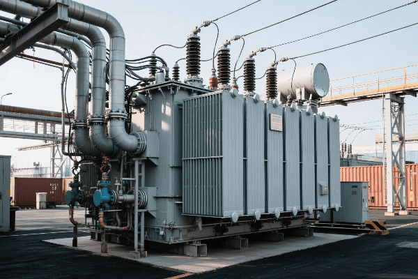
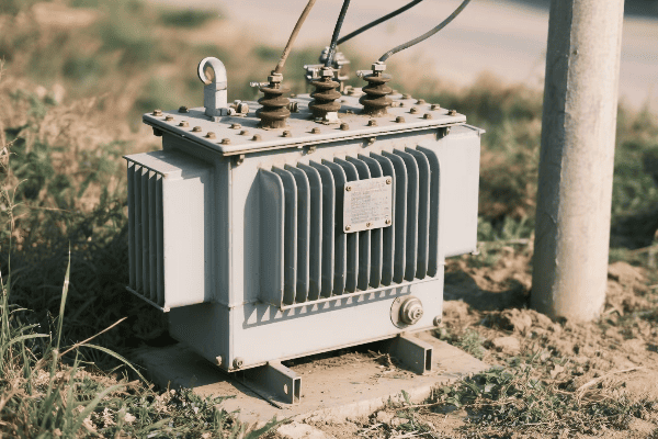
Power transformers and distribution transformers serve distinct functions in the electrical grid. Power transformers handle high voltages and large power capacities, typically found in power plants and substations. Distribution transformers operate at lower voltages and are used to supply power directly to consumers.
In this article, I’ll explain the key differences between power and distribution transformers. My experience in designing and working with both types has taught me the crucial distinctions that impact their applications in the electrical grid.
How Do Power Transformers and Distribution Transformers Differ in Their Voltage Handling Capabilities?
When I first started working with transformers, I was amazed by the vast difference in voltage levels they could handle. This difference is fundamental to their roles in the power system.
Power transformers typically handle voltages from 69 kV up to 765 kV or higher, facilitating long-distance power transmission. Distribution transformers, on the other hand, step down voltages to levels suitable for end-users, usually from 4 kV to 34.5 kV on the primary side to 120/240 V on the secondary side.
Let’s dive deeper into the voltage handling capabilities of these transformers:
Power Transformers: High Voltage Champions
Power transformers are designed for high voltage applications. I once worked on a project involving a 500 kV power transformer. The sheer size and complexity of its insulation system were impressive.
- Primary Voltage Range: Typically 69 kV to 765 kV or higher
- Secondary Voltage Range: Often steps down to sub-transmission voltages (e.g., 69 kV to 138 kV)
- Insulation Requirements: Extensive and complex due to high voltages
Distribution Transformers: Bringing Power to Consumers
Distribution transformers operate at much lower voltages. In a recent residential project, we used transformers that stepped down 12.47 kV to 120/240 V for household use.
| Aspect | Primary Side | Secondary Side |
|---|---|---|
| Voltage Range | 4 kV to 34.5 kV | 120/240 V to 480 V |
| Insulation | Less complex | Standard for low voltage |
| BIL (Basic Impulse Level) | Lower than power transformers | Designed for end-user safety |
Voltage Regulation Capabilities
The ability to regulate voltage differs between these transformer types:
- Power Transformers: Often equipped with on-load tap changers for voltage regulation
- Distribution Transformers: Usually have off-load tap changers or no tap changers at all
I remember a case where we had to retrofit a power transformer with an advanced on-load tap changer to improve voltage stability in a growing industrial area.
Impact on System Design
The voltage handling capabilities of these transformers significantly impact overall system design:
- Power Transformers: Key in determining transmission line voltages and substation configurations
- Distribution Transformers: Influence the layout and capacity of local distribution networks
In my experience, understanding these voltage capabilities is crucial for effective power system planning and operation.
What Are the Distinct Roles of Power Transformers and Distribution Transformers in the Electrical Grid?
Understanding the roles of power and distribution transformers is key to grasping how our electrical grid functions. I’ve seen firsthand how these different transformers work together to keep our lights on.
Power transformers play a crucial role in bulk power transmission, facilitating the transfer of large amounts of electricity over long distances. Distribution transformers are the final link in the power delivery chain, stepping down voltage to levels suitable for homes and businesses.
Let’s explore the distinct roles of these transformers:
Power Transformers: The Backbone of Transmission
Power transformers are vital in the transmission network. I once worked on upgrading a substation where the power transformer was the centerpiece of the entire operation.
- Step-Up Transformation: At power plants, increasing generator voltage for efficient transmission
- Bulk Power Transfer: Enabling the movement of large amounts of power across the grid
- Interconnection: Facilitating power exchange between different regions or countries
Distribution Transformers: Bringing Power to the People
Distribution transformers are the unsung heroes of our local power supply. In a recent urban development project, I saw how crucial these transformers were in powering an entire neighborhood.
| Function | Power Transformer | Distribution Transformer |
|---|---|---|
| Location | Power plants, Substations | Neighborhoods, Poles, Pad-mounted |
| Power Capacity | Typically > 10 MVA | Usually < 5 MVA |
| End Users | Other substations, Large industries | Homes, Small businesses |
System Stability and Reliability
Both types of transformers contribute to system stability, but in different ways:
- Power Transformers: Crucial for overall grid stability and power flow control
- Distribution Transformers: Essential for local voltage regulation and power quality
I recall a project where we had to carefully coordinate the protection settings of power and distribution transformers to ensure seamless operation during fault conditions.
Energy Loss Considerations
The role of these transformers in managing energy losses is significant:
- Power Transformers: Focus on minimizing losses for large-scale efficiency
- Distribution Transformers: Balancing efficiency with cost for widespread deployment
In my experience, even small improvements in distribution transformer efficiency can lead to significant energy savings across the grid.
Future Grid Integration
As our grid evolves, so do the roles of these transformers:
- Power Transformers: Adapting to integrate large-scale renewable energy sources
- Distribution Transformers: Evolving to handle bi-directional power flow in smart grids
I’m currently involved in a project exploring how distribution transformers can better accommodate distributed energy resources like rooftop solar panels.
How Do Design and Construction Features Vary Between Power and Distribution Transformers?
The design and construction of power and distribution transformers reflect their distinct roles and operating conditions. I’ve had the opportunity to work on both types, and the differences are fascinating.
Power transformers are typically larger, custom-designed units with advanced cooling systems and robust mechanical structures to handle high voltages and power levels. Distribution transformers are smaller, often standardized units designed for cost-effective production and easier installation in various locations.
Let’s explore the key design and construction differences:
Core and Winding Design
The core and winding designs vary significantly:
-
Power Transformers:
- Often use shell-type cores for better mechanical strength
- Complex winding arrangements to handle high currents
- Advanced insulation systems for high voltage stress
-
Distribution Transformers:
- Typically use simpler core-type designs
- More standardized winding arrangements
- Insulation designed for lower voltage applications
I once worked on a power transformer design that used a novel core material to reduce losses. The complexity of integrating this material into the large core structure was a significant engineering challenge.
Cooling Systems
Cooling system design is a critical difference:
| Aspect | Power Transformer | Distribution Transformer |
|---|---|---|
| Cooling Methods | ONAN, ONAF, OFAF, ODAF | Mainly ONAN |
| Oil Volume | Large oil volumes | Smaller oil volumes or dry-type |
| Radiators | Often extensive radiator banks | Simple radiators or tanks |
In a recent project, we had to design a custom cooling system for a large power transformer located in an extremely hot climate. The solution involved a combination of forced oil and forced air cooling (OFAF) with additional heat exchangers.
Tap Changers
Tap changer designs differ significantly:
-
Power Transformers:
- Often equipped with on-load tap changers (OLTC)
- Complex mechanisms for voltage regulation under load
- Wide range of tap positions
-
Distribution Transformers:
- Usually have off-load tap changers or no tap changers
- Simpler designs with fewer tap positions
- Manual adjustment when de-energized
I remember a challenging project where we had to retrofit an OLTC onto an existing power transformer to improve voltage regulation in a rapidly growing industrial area.
Bushings and Terminals
The design of bushings and terminals also varies:
-
Power Transformers:
- Large, complex bushings for high voltage insulation
- Often oil-filled or SF6 gas-filled bushings
- Robust terminal designs for high current capacity
-
Distribution Transformers:
- Simpler, smaller bushings
- Often solid or polymer-type insulators
- Standardized terminal configurations for easy connection
In my experience, the design of power transformer bushings can be as complex as the transformer itself, especially for ultra-high voltage applications.
Monitoring and Protection
The level of monitoring and protection differs:
-
Power Transformers:
- Extensive monitoring systems (temperature, gas, partial discharge)
- Complex protection schemes
- Often include online monitoring and diagnostics
-
Distribution Transformers:
- Basic overload and short-circuit protection
- Simple temperature monitoring
- Generally rely on external protection devices
I’ve been involved in implementing advanced monitoring systems for power transformers that can predict potential failures weeks in advance, significantly improving reliability and maintenance planning.
What Are the Efficiency and Loss Considerations for Power Transformers vs. Distribution Transformers?
Efficiency and loss considerations are crucial in transformer design and operation. I’ve spent a significant part of my career optimizing these aspects for both power and distribution transformers.
Power transformers typically have higher efficiency ratings due to their larger size and the critical nature of their role in the grid. Distribution transformers, while also designed for efficiency, must balance performance with cost-effectiveness for widespread deployment. Both types focus on minimizing core and winding losses, but the approaches differ.
Let’s delve into the efficiency and loss considerations for both types:
Types of Losses
Both transformer types experience two main types of losses:
-
No-Load Losses (Core Losses):
- Occur whenever the transformer is energized
- Caused by the magnetization and demagnetization of the core
-
Load Losses (Copper Losses):
- Vary with the load on the transformer
- Caused by resistance in the windings
In my experience, balancing these losses is a key challenge in transformer design.
Efficiency Ratings
Efficiency ratings differ between the two types:
| Aspect | Power Transformer | Distribution Transformer |
|---|---|---|
| Typical Efficiency | 99.5% – 99.9% | 98% – 99% |
| Rated Load | Often designed for optimal efficiency at 50-70% load | Typically optimized for 35-50% load |
| Efficiency Standards | IEC 60076-20, IEEE C57.12.00 | DOE 10 CFR Part 431, EU Ecodesign |
I once worked on a project to upgrade a substation’s power transformers. By choosing high-efficiency units, we were able to reduce energy losses by over 20%, resulting in significant cost savings for the utility.
Core Material and Design
The choice of core material significantly impacts efficiency:
-
Power Transformers:
- Often use higher grade silicon steel or amorphous metals
- Complex core designs to minimize flux path length
- Larger core cross-sections to reduce flux density
-
Distribution Transformers:
- Balancing cost and performance with silicon steel grades
- Simpler core designs for ease of manufacturing
- Optimized core sizes for standard ratings
In a recent distribution transformer design project, we experimented with different core materials to find the optimal balance between efficiency and cost.
Winding Design and Materials
Winding design also plays a crucial role in efficiency:
-
Power Transformers:
- Often use continuously transposed conductors (CTC) to reduce eddy current losses
- Complex winding geometries to optimize current distribution
- Sometimes use exotic materials like superconductors for ultra-high efficiency
-
Distribution Transformers:
- Simpler winding designs for cost-effective production
- Focus on optimizing conductor sizes and arrangements
- Sometimes use aluminum instead of copper for cost savings
I’ve been involved in projects where we used advanced simulation tools to optimize winding designs, resulting in significant reductions in load losses.
Cooling System Efficiency
The efficiency of the cooling system is another important factor:
-
Power Transformers:
- Advanced cooling systems (OFAF, ODAF) for better heat dissipation
- Use of low-loss cooling fans and pumps
- Sometimes employ directed oil flow techniques for targeted cooling
-
Distribution Transformers:
- Simpler ONAN cooling sufficient for most applications
- Design focus on natural convection efficiency
- Sometimes use special tank designs to enhance cooling without active components
In a recent power transformer project, we implemented a smart cooling control system that adjusted cooling intensity based on load and ambient conditions, significantly improving overall efficiency.
How Do Maintenance and Monitoring Requirements Differ for Power and Distribution Transformers?
Maintenance and monitoring are critical for ensuring the longevity and reliability of transformers. In my years of working with both power and distribution transformers, I’ve seen how these requirements can vary significantly.
Power transformers typically require more intensive and frequent maintenance due to their critical role and complex design. They often have advanced monitoring systems for real-time performance tracking. Distribution transformers, being simpler and more numerous, usually have less intensive maintenance schedules and rely more on periodic inspections and testing.
Let’s explore the differences in maintenance and monitoring requirements:
Routine Maintenance Schedules
The frequency and depth of routine maintenance differ:
-
Power Transformers:
- Often have monthly, quarterly, and annual maintenance schedules
- Involve comprehensive checks of all major components
- May require planned outages for detailed inspections
-
Distribution Transformers:
- Typically have annual or bi-annual inspection schedules
- Focus on external condition checks and basic electrical tests
- Often maintained on a "run to failure" basis in some utilities
I once managed a maintenance program for a fleet of power transformers where we implemented a condition-based maintenance approach. This significantly reduced unnecessary maintenance while improving reliability.
Oil Testing and Analysis
Oil testing is a crucial aspect of transformer maintenance:
| Aspect | Power Transformer | Distribution Transformer |
|---|---|---|
| Frequency | Often quarterly or bi-annual | Typically annual or less frequent |
| Tests Performed | Comprehensive DGA, furan analysis, oil quality tests | Basic oil quality tests, sometimes DGA |
| Sampling Points | Multiple sampling points for detailed analysis | Usually single sampling point |
In a recent project, we introduced online DGA monitoring for critical power transformers. This allowed us to detect a developing fault early, preventing a potential failure that could have cost millions in downtime.
Electrical Testing
Electrical testing requirements vary:
-
Power Transformers:
- Regular power factor testing
- Winding resistance and ratio tests
- Insulation resistance and polarization index tests
- Sometimes include frequency response analysis (FRA)
-
Distribution Transformers:
- Basic insulation resistance tests
- Turn ratio tests at longer intervals
- Often rely on load current and voltage measurements for performance indication
I recall a case where regular FRA testing on a power transformer helped us identify a minor core displacement early, allowing for timely corrective action.
Monitoring Systems
The complexity of monitoring systems differs significantly:
-
Power Transformers:
- Often equipped with online monitoring systems
- Real-time tracking of temperatures, gas levels, partial discharges
- Integration with SCADA systems for remote monitoring
- Sometimes include advanced analytics for predictive maintenance
-
Distribution Transformers:
- Usually limited to basic overload and short-circuit protection
- Some modern units include simple temperature and load monitoring
- Increasingly incorporating smart grid functionalities in urban areas
I’ve been involved in implementing advanced monitoring systems for power transformers that use AI algorithms to predict potential failures. This technology has revolutionized our approach to transformer maintenance.
Physical Inspections
The nature of physical inspections varies:
-
Power Transformers:
- Detailed visual inspections of all components
- Regular checks of cooling systems, bushings, and tap changers
- Thermographic surveys to detect hot spots
-
Distribution Transformers:
- Often limited to external visual inspections
- Check for oil leaks, corrosion, and damage to bushings
- Inspection of connections and grounding
In my experience, regular and thorough physical inspections are invaluable. I once discovered a minor oil leak during a routine inspection of a power transformer, which, if left unchecked, could have led to a major failure.
Bushing Maintenance
Bushing maintenance is another area of difference:
-
Power Transformers:
- Regular testing of bushing power factor and capacitance
- Oil level checks in oil-filled bushings
- Sometimes require specialized equipment for testing and maintenance
-
Distribution Transformers:
- Visual inspection of bushing condition
- Cleaning of bushing surfaces to prevent flashovers
- Simpler replacement procedures when necessary
I remember a project where we had to develop a custom maintenance procedure for ultra-high voltage bushings on a power transformer. The complexity of these components often surprises even experienced engineers.
Tap Changer Maintenance
Tap changer maintenance requirements differ significantly:
-
Power Transformers:
- Regular maintenance of on-load tap changers (OLTC)
- Oil filtering or replacement in OLTC compartments
- Mechanical wear checks and contact resistance measurements
-
Distribution Transformers:
- Infrequent checks of off-load tap changers
- Usually limited to ensuring proper tap position and connection integrity
In my career, I’ve seen how neglected OLTC maintenance can lead to severe issues. We once had to perform an emergency repair on a power transformer OLTC that had failed due to lack of proper maintenance, causing a significant outage.
Documentation and Record Keeping
The approach to documentation varies:
-
Power Transformers:
- Detailed maintenance logs and test reports
- Comprehensive historical records for trend analysis
- Often use specialized asset management software
-
Distribution Transformers:
- Basic maintenance records, often part of a broader distribution system database
- Less emphasis on individual transformer history due to large numbers
I’ve implemented digital record-keeping systems for power transformer fleets, which greatly improved our ability to predict and prevent failures through trend analysis.
Conclusion
Power and distribution transformers, while both crucial to the electrical grid, have distinct differences in voltage handling, roles, design, efficiency, and maintenance needs. Understanding these differences is key to effective grid management and operation.
Have you ever wondered why some pad mounted transformers fail prematurely? The answer often lies beneath the surface, in the concrete pad they’re installed on.
Proper installation of concrete pads for pad mounted transformers is crucial for utility companies. It ensures transformer stability, longevity, and safety. Best practices include correct pad design, proper site preparation, adherence to safety regulations, and consideration of environmental factors.
In this article, I’ll share my insights on concrete pad installation for pad mounted transformers. I’ve seen firsthand how a well-designed pad can make all the difference in transformer performance and maintenance.
What Are the Key Considerations for Designing and Preparing a Concrete Pad for Pad Mounted Transformers?
When I first started working with pad mounted transformers, I underestimated the importance of the concrete pad. I quickly learned that a poorly designed pad can lead to a host of problems.
Key considerations for concrete pad design include load-bearing capacity, dimensions, drainage, conduit placement, and soil conditions. The pad must support the transformer’s weight, allow for proper cable entry, and ensure adequate drainage to prevent water accumulation.
Let’s dive deeper into these key considerations:
Load-Bearing Capacity
The pad’s load-bearing capacity is crucial. I once worked on a project where an undersized pad cracked under the transformer’s weight. We had to replace both the pad and the transformer, a costly mistake that could have been avoided with proper design.
- Transformer Weight: Pads must support the full weight of the transformer.
- Oil Weight: For oil-filled transformers, factor in the oil weight.
- Safety Factor: Include a safety margin for additional loads.
Dimensions and Thickness
Pad dimensions are critical. In a recent project, we designed a pad with extended dimensions to accommodate future transformer upgrades. This foresight saved the utility company significant costs down the line.
| Aspect | Consideration |
|---|---|
| Length and Width | Must extend beyond transformer footprint |
| Thickness | Depends on soil conditions and transformer weight |
| Reinforcement | Steel rebar for added strength |
Drainage and Slope
Proper drainage is essential. I remember a site where poor drainage led to water pooling around the transformer. We had to retrofit a drainage system, which was much more expensive than if it had been included in the initial design.
- Slope: Typically 1% away from the transformer.
- Surrounding Area: Grade the area to direct water away.
- Drainage Channels: Consider adding channels in flood-prone areas.
Conduit Placement
Conduit placement requires careful planning. In one project, we used a template to ensure precise conduit placement. This made cable installation much easier and reduced the risk of damage to the cables during installation.
- Primary Conduits: For incoming high-voltage cables.
- Secondary Conduits: For outgoing low-voltage cables.
- Future Expansion: Include spare conduits for potential upgrades.
Soil Conditions
Soil conditions significantly impact pad design. I once worked on a site with expansive clay soil. We had to design a special pad with a deeper foundation to prevent movement and cracking.
- Soil Testing: Conduct geotechnical surveys.
- Compaction: Ensure proper soil compaction before pouring concrete.
- Frost Heave: In cold climates, consider frost heave protection.
How Does Proper Concrete Pad Installation Affect the Performance and Longevity of Pad Mounted Transformers?
Early in my career, I saw a transformer fail due to a poorly installed pad. It was a wake-up call that showed me how crucial proper installation is.
Proper concrete pad installation significantly impacts transformer performance and longevity. It ensures stability, prevents water ingress, facilitates heat dissipation, and enables easy maintenance access. A well-installed pad can extend a transformer’s lifespan and reduce the risk of failures.
Let’s explore how proper installation affects transformers:
Stability and Vibration Reduction
A properly installed pad provides stability. I once worked on a project in a seismic zone. We designed a pad with special anchoring systems that significantly improved the transformer’s ability to withstand earthquakes.
- Level Surface: Prevents transformer tilting.
- Vibration Absorption: Reduces operational vibrations.
- Seismic Protection: In earthquake-prone areas, proper installation is crucial.
Water Protection
Water is a transformer’s enemy. Good pad installation helps. In a coastal project, we used a raised pad design with special sealants. It successfully protected the transformer from saltwater corrosion and flooding.
| Aspect | Benefit |
|---|---|
| Elevation | Keeps transformer above flood levels |
| Slope | Directs water away from the transformer |
| Sealant | Prevents water ingress through conduit entries |
Heat Dissipation
Proper pad installation aids in heat dissipation. I remember a case where poor air circulation led to transformer overheating. By redesigning the pad with better clearance, we solved the issue and extended the transformer’s life.
- Air Circulation: Adequate clearance allows airflow.
- Thermal Mass: Concrete acts as a heat sink.
- Surface Treatment: Reflective coatings can reduce heat absorption.
Maintenance Access
A well-designed pad facilitates maintenance. In one project, we incorporated a built-in oil containment system into the pad design. It not only met environmental regulations but also made oil changes and spill cleanups much easier.
- Working Space: Ensures enough room for technicians.
- Equipment Access: Allows for easy replacement of components.
- Oil Containment: Proper design can include oil containment features.
Long-Term Cost Savings
Proper installation leads to cost savings. I’ve seen utilities save millions in the long run by investing in proper pad installation upfront. It’s a classic case of "pay now or pay more later."
- Reduced Failures: Fewer transformer failures mean less downtime.
- Extended Lifespan: Well-supported transformers last longer.
- Lower Maintenance Costs: Easier access reduces maintenance time and costs.
What Safety Measures and Regulations Should Utility Companies Follow During Concrete Pad Installation?
Safety is paramount in utility work. I’ve seen the consequences of neglecting safety measures, and it’s not pretty.
Utility companies must follow strict safety measures and regulations during concrete pad installation. These include adherence to OSHA standards, proper equipment usage, electrical safety protocols, and environmental protection measures. Compliance ensures worker safety and prevents accidents.
Let’s delve into the key safety measures and regulations:
OSHA Compliance
OSHA standards are crucial. I once consulted on a project where strict adherence to OSHA standards prevented a potentially serious accident during excavation. It reinforced the importance of these regulations.
- Personal Protective Equipment (PPE): Hard hats, safety boots, gloves.
- Fall Protection: When working at heights.
- Trench Safety: For excavation work.
Equipment Safety
Proper equipment usage is essential. In a recent project, we implemented a comprehensive equipment safety program. It reduced accidents and improved overall efficiency.
| Equipment | Safety Measure |
|---|---|
| Concrete Mixers | Regular maintenance, proper operation training |
| Excavators | Certified operators, clear communication protocols |
| Power Tools | Proper grounding, GFCI protection |
Electrical Safety
Electrical safety is paramount. I remember a close call where a worker almost contacted a live wire. Our strict electrical safety protocols prevented what could have been a fatal accident.
- De-energization: Ensure all nearby power sources are off.
- Lockout/Tagout: Use proper procedures to prevent accidental energization.
- Grounding: Properly ground all equipment.
Environmental Protection
Environmental considerations are important. In an urban project, we used innovative low-noise equipment and dust control measures. It helped maintain good relations with the surrounding community.
- Spill Prevention: Have containment measures for concrete and chemicals.
- Dust Control: Use water sprays to minimize dust.
- Noise Reduction: Schedule noisy work during appropriate hours.
Site Security
Securing the site is crucial. I’ve seen how proper site security can prevent vandalism and theft. In one project, our security measures deterred copper thieves, saving the utility company significant costs.
- Fencing: Erect temporary fencing around the work area.
- Signage: Clear warning signs about the construction.
- Access Control: Limit site access to authorized personnel only.
How Can Utility Companies Optimize the Concrete Pad Layout for Efficient Transformer Maintenance and Access?
Efficient maintenance is key to transformer longevity. I’ve seen how a well-designed pad layout can make a huge difference in maintenance operations.
Utility companies can optimize concrete pad layout by ensuring adequate working space, strategic placement of access points, incorporation of oil containment features, and consideration of future expansion. An optimized layout facilitates easier maintenance, reduces downtime, and improves overall efficiency.
Let’s explore ways to optimize pad layout:
Working Space
Adequate working space is crucial. In a recent project, we designed a pad with extra clearance on one side. This "maintenance alley" greatly improved the efficiency of routine checks and repairs.
- Clearance: Allow enough room around all sides of the transformer.
- Access Paths: Clear paths for maintenance vehicles and equipment.
- Staging Areas: Designate areas for tools and replacement parts.
Strategic Access Points
Placement of access points is key. I once redesigned a pad layout to relocate the control cabinet. This simple change reduced maintenance time by 30% by improving accessibility.
| Access Point | Consideration |
|---|---|
| Cable Entry | Easy access for cable replacement |
| Oil Drain | Accessible for oil changes |
| Control Cabinet | Clear view and easy reach |
Oil Containment
Incorporating oil containment features is important. In an environmentally sensitive area, we designed a pad with an integrated oil containment system. It not only met regulations but also simplified maintenance procedures.
- Containment Basin: Built into the pad design.
- Drainage System: For safe oil removal.
- Capacity: Sized to contain the full volume of transformer oil.
Future Expansion
Planning for the future is wise. I worked on a substation where we implemented a modular pad design. When the utility needed to upgrade the transformer years later, the expansion was straightforward and cost-effective.
- Oversized Pad: Allow room for larger transformers.
- Extra Conduits: Install spare conduits for future needs.
- Modular Design: Enable easy expansion of the pad.
Ergonomic Considerations
Ergonomics can improve maintenance efficiency. In one project, we incorporated ergonomic features like adjustable work platforms. It significantly reduced strain on maintenance workers and improved their efficiency.
- Height: Design the pad height for comfortable working postures.
- Surface Texture: Non-slip surfaces for safety.
- Lighting: Consider built-in lighting for nighttime maintenance.
What Are the Environmental and Aesthetic Considerations in Concrete Pad Design for Urban and Suburban Areas?
In urban and suburban areas, transformers can’t just be functional – they need to blend in. I’ve worked on projects where environmental and aesthetic considerations were just as important as technical specs.
Environmental and aesthetic considerations in concrete pad design include using eco-friendly materials, implementing green spaces, noise reduction measures, and visual camouflage techniques. These factors help utilities meet regulations, improve community relations, and enhance the overall urban landscape.
Let’s explore these considerations:
Eco-Friendly Materials
Using sustainable materials is increasingly important. In a recent urban project, we used recycled concrete for the pad. It not only met performance standards but also helped the utility meet its sustainability goals.
- Recycled Concrete: Reduces environmental impact.
- Permeable Surfaces: Allows water to seep through, reducing runoff.
- Low-Carbon Cement: Reduces the carbon footprint of the installation.
Green Space Integration
Incorporating green spaces can improve aesthetics. I once designed a pad that included a small rain garden. It not only looked great but also helped manage stormwater runoff.
| Feature | Benefit |
|---|---|
| Planting Areas | Softens the visual impact |
| Green Walls | Vertical gardens on screening walls |
| Bioswales | Natural drainage and filtration |
Noise Reduction
Minimizing noise is crucial in residential areas. In a suburban project, we used special vibration-dampening mounts on the pad. It significantly reduced noise complaints from nearby residents.
- Sound-Absorbing Materials: Use in pad and enclosure design.
- Vibration Dampening: Install vibration isolators.
- Strategic Placement: Position transformers away from sensitive areas.
Visual Camouflage
Blending the transformer into its surroundings is an art. I worked on a project in a historic district where we designed a pad and enclosure that mimicked a traditional garden shed. It preserved the area’s character while housing modern equipment.
- Color Matching: Use colors that complement the environment.
- Artistic Enclosures: Collaborate with local artists for creative designs.
- Landscaping: Use plants to screen the transformer.
Community Engagement
Involving the community can lead to better outcomes. In one project, we partnered with a local school to create an educational garden around the transformer pad. It turned a potential eyesore into a community asset.
- Public Consultations: Gather input on design preferences.
- Educational Signage: Inform the public about the transformer’s role.
- Local Partnerships: Work with local organizations for maintenance of surrounding areas.
Conclusion
Proper concrete pad installation is crucial for pad mounted transformers. It ensures stability, safety, and longevity while addressing environmental and aesthetic concerns. Utility companies must consider all aspects for optimal performance and community acceptance.
Have you ever wondered why some power transformers seem to last forever while others fail prematurely? The secret often lies beneath the surface, in the concrete pad they’re installed on.
Proper installation of concrete pads for pad mounted transformers is crucial for utility companies. It ensures transformer stability, longevity, and safety. Best practices include correct pad design, proper site preparation, adherence to safety regulations, and consideration of environmental factors.
In this article, I’ll share my insights on concrete pad installation for pad mounted transformers. I’ve seen firsthand how a well-designed pad can make all the difference in transformer performance and maintenance.
What Are the Key Considerations for Designing and Preparing a Concrete Pad for Pad Mounted Transformers?
When I first started working with pad mounted transformers, I underestimated the importance of the concrete pad. I quickly learned that a poorly designed pad can lead to a host of problems.
Key considerations for concrete pad design include load-bearing capacity, dimensions, drainage, conduit placement, and soil conditions. The pad must support the transformer’s weight, allow for proper cable entry, and ensure adequate drainage to prevent water accumulation.
Let’s dive deeper into these key considerations:
Load-Bearing Capacity
The pad’s load-bearing capacity is crucial:
- Transformer Weight: Pads must support the full weight of the transformer.
- Oil Weight: For oil-filled transformers, factor in the oil weight.
- Safety Factor: Include a safety margin for additional loads.
I once worked on a project where an undersized pad cracked under the transformer’s weight. We had to replace both the pad and the transformer, a costly mistake that could have been avoided with proper design.
Dimensions and Thickness
Pad dimensions are critical:
| Aspect | Consideration |
|---|---|
| Length and Width | Must extend beyond transformer footprint |
| Thickness | Depends on soil conditions and transformer weight |
| Reinforcement | Steel rebar for added strength |
In a recent project, we designed a pad with extended dimensions to accommodate future transformer upgrades. This foresight saved the utility company significant costs down the line.
Drainage and Slope
Proper drainage is essential:
- Slope: Typically 1% away from the transformer.
- Surrounding Area: Grade the area to direct water away.
- Drainage Channels: Consider adding channels in flood-prone areas.
I remember a site where poor drainage led to water pooling around the transformer. We had to retrofit a drainage system, which was much more expensive than if it had been included in the initial design.
Conduit Placement
Conduit placement requires careful planning:
- Primary Conduits: For incoming high-voltage cables.
- Secondary Conduits: For outgoing low-voltage cables.
- Future Expansion: Include spare conduits for potential upgrades.
In one project, we used a template to ensure precise conduit placement. This made cable installation much easier and reduced the risk of damage to the cables during installation.
Soil Conditions
Soil conditions significantly impact pad design:
- Soil Testing: Conduct geotechnical surveys.
- Compaction: Ensure proper soil compaction before pouring concrete.
- Frost Heave: In cold climates, consider frost heave protection.
I once worked on a site with expansive clay soil. We had to design a special pad with a deeper foundation to prevent movement and cracking.
How Does Proper Concrete Pad Installation Affect the Performance and Longevity of Pad Mounted Transformers?
Early in my career, I saw a transformer fail due to a poorly installed pad. It was a wake-up call that showed me how crucial proper installation is.
Proper concrete pad installation significantly impacts transformer performance and longevity. It ensures stability, prevents water ingress, facilitates heat dissipation, and enables easy maintenance access. A well-installed pad can extend a transformer’s lifespan and reduce the risk of failures.
Let’s explore how proper installation affects transformers:
Stability and Vibration Reduction
A properly installed pad provides stability:
- Level Surface: Prevents transformer tilting.
- Vibration Absorption: Reduces operational vibrations.
- Seismic Protection: In earthquake-prone areas, proper installation is crucial.
I once worked on a project in a seismic zone. We designed a pad with special anchoring systems that significantly improved the transformer’s ability to withstand earthquakes.
Water Protection
Water is a transformer’s enemy. Good pad installation helps:
| Aspect | Benefit |
|---|---|
| Elevation | Keeps transformer above flood levels |
| Slope | Directs water away from the transformer |
| Sealant | Prevents water ingress through conduit entries |
In a coastal project, we used a raised pad design with special sealants. It successfully protected the transformer from saltwater corrosion and flooding.
Heat Dissipation
Proper pad installation aids in heat dissipation:
- Air Circulation: Adequate clearance allows airflow.
- Thermal Mass: Concrete acts as a heat sink.
- Surface Treatment: Reflective coatings can reduce heat absorption.
I remember a case where poor air circulation led to transformer overheating. By redesigning the pad with better clearance, we solved the issue and extended the transformer’s life.
Maintenance Access
A well-designed pad facilitates maintenance:
- Working Space: Ensures enough room for technicians.
- Equipment Access: Allows for easy replacement of components.
- Oil Containment: Proper design can include oil containment features.
In one project, we incorporated a built-in oil containment system into the pad design. It not only met environmental regulations but also made oil changes and spill cleanups much easier.
Long-Term Cost Savings
Proper installation leads to cost savings:
- Reduced Failures: Fewer transformer failures mean less downtime.
- Extended Lifespan: Well-supported transformers last longer.
- Lower Maintenance Costs: Easier access reduces maintenance time and costs.
I’ve seen utilities save millions in the long run by investing in proper pad installation upfront. It’s a classic case of "pay now or pay more later."
What Safety Measures and Regulations Should Utility Companies Follow During Concrete Pad Installation?
Safety is paramount in utility work. I’ve seen the consequences of neglecting safety measures, and it’s not pretty.
Utility companies must follow strict safety measures and regulations during concrete pad installation. These include adherence to OSHA standards, proper equipment usage, electrical safety protocols, and environmental protection measures. Compliance ensures worker safety and prevents accidents.
Let’s delve into the key safety measures and regulations:
OSHA Compliance
OSHA standards are crucial:
- Personal Protective Equipment (PPE): Hard hats, safety boots, gloves.
- Fall Protection: When working at heights.
- Trench Safety: For excavation work.
I once consulted on a project where strict adherence to OSHA standards prevented a potentially serious accident during excavation. It reinforced the importance of these regulations.
Equipment Safety
Proper equipment usage is essential:
| Equipment | Safety Measure |
|---|---|
| Concrete Mixers | Regular maintenance, proper operation training |
| Excavators | Certified operators, clear communication protocols |
| Power Tools | Proper grounding, GFCI protection |
In a recent project, we implemented a comprehensive equipment safety program. It reduced accidents and improved overall efficiency.
Electrical Safety
Electrical safety is paramount:
- De-energization: Ensure all nearby power sources are off.
- Lockout/Tagout: Use proper procedures to prevent accidental energization.
- Grounding: Properly ground all equipment.
I remember a close call where a worker almost contacted a live wire. Our strict electrical safety protocols prevented what could have been a fatal accident.
Environmental Protection
Environmental considerations are important:
- Spill Prevention: Have containment measures for concrete and chemicals.
- Dust Control: Use water sprays to minimize dust.
- Noise Reduction: Schedule noisy work during appropriate hours.
In an urban project, we used innovative low-noise equipment and dust control measures. It helped maintain good relations with the surrounding community.
Site Security
Securing the site is crucial:
- Fencing: Erect temporary fencing around the work area.
- Signage: Clear warning signs about the construction.
- Access Control: Limit site access to authorized personnel only.
I’ve seen how proper site security can prevent vandalism and theft. In one project, our security measures deterred copper thieves, saving the utility company significant costs.
How Can Utility Companies Optimize the Concrete Pad Layout for Efficient Transformer Maintenance and Access?
Efficient maintenance is key to transformer longevity. I’ve seen how a well-designed pad layout can make a huge difference in maintenance operations.
Utility companies can optimize concrete pad layout by ensuring adequate working space, strategic placement of access points, incorporation of oil containment features, and consideration of future expansion. An optimized layout facilitates easier maintenance, reduces downtime, and improves overall efficiency.

Let’s explore ways to optimize pad layout:
Working Space
Adequate working space is crucial:
- Clearance: Allow enough room around all sides of the transformer.
- Access Paths: Clear paths for maintenance vehicles and equipment.
- Staging Areas: Designate areas for tools and replacement parts.
In a recent project, we designed a pad with extra clearance on one side. This "maintenance alley" greatly improved the efficiency of routine checks and repairs.
Strategic Access Points
Placement of access points is key:
| Access Point | Consideration |
|---|---|
| Cable Entry | Easy access for cable replacement |
| Oil Drain | Accessible for oil changes |
| Control Cabinet | Clear view and easy reach |
I once redesigned a pad layout to relocate the control cabinet. This simple change reduced maintenance time by 30% by improving accessibility.
Oil Containment
Incorporating oil containment features is important:
- Containment Basin: Built into the pad design.
- Drainage System: For safe oil removal.
- Capacity: Sized to contain the full volume of transformer oil.
In an environmentally sensitive area, we designed a pad with an integrated oil containment system. It not only met regulations but also simplified maintenance procedures.
Future Expansion
Planning for the future is wise:
- Oversized Pad: Allow room for larger transformers.
- Extra Conduits: Install spare conduits for future needs.
- Modular Design: Enable easy expansion of the pad.
I worked on a substation where we implemented a modular pad design. When the utility needed to upgrade the transformer years later, the expansion was straightforward and cost-effective.
Ergonomic Considerations
Ergonomics can improve maintenance efficiency:
- Height: Design the pad height for comfortable working postures.
- Surface Texture: Non-slip surfaces for safety.
- Lighting: Consider built-in lighting for nighttime maintenance.
In one project, we incorporated ergonomic features like adjustable work platforms. It significantly reduced strain on maintenance workers and improved their efficiency.
What Are the Environmental and Aesthetic Considerations in Concrete Pad Design for Urban and Suburban Areas?
In urban and suburban areas, transformers can’t just be functional – they need to blend in. I’ve worked on projects where environmental and aesthetic considerations were just as important as technical specs.
Environmental and aesthetic considerations in concrete pad design include using eco-friendly materials, implementing green spaces, noise reduction measures, and visual camouflage techniques. These factors help utilities meet regulations, improve community relations, and enhance the overall urban landscape.

Let’s explore these considerations:
Eco-Friendly Materials
Using sustainable materials is increasingly important:
- Recycled Concrete: Reduces environmental impact.
- Permeable Surfaces: Allows water to seep through, reducing runoff.
- Low-Carbon Cement: Reduces the carbon footprint of the installation.
In a recent urban project, we used recycled concrete for the pad. It not only met performance standards but also helped the utility meet its sustainability goals.
Green Space Integration
Incorporating green spaces can improve aesthetics:
| Feature | Benefit |
|---|---|
| Planting Areas | Softens the visual impact |
| Green Walls | Vertical gardens on screening walls |
| Bioswales | Natural drainage and filtration |
I once designed a pad that included a small rain garden. It not only looked great but also helped manage stormwater runoff.
Noise Reduction
Minimizing noise is crucial in residential areas:
- Sound-Absorbing Materials: Use in pad and enclosure design.
- Vibration Dampening: Install vibration isolators.
- Strategic Placement: Position transformers away from sensitive areas.
In a suburban project, we used special vibration-dampening mounts on the pad. It significantly reduced noise complaints from nearby residents.
Visual Camouflage
Blending the transformer into its surroundings is an art:
- Color Matching: Use colors that complement the environment.
- Artistic Enclosures: Collaborate with local artists for creative designs.
- Landscaping: Use plants to screen the transformer.
I worked on a project in a historic district where we designed a pad and enclosure that mimicked a traditional garden shed. It preserved the area’s character while housing modern equipment.
Community Engagement
Involving the community can lead to better outcomes:
- Public Consultations: Gather input on design preferences.
- Educational Signage: Inform the public about the transformer’s role.
- Local Partnerships: Work with local organizations for maintenance of surrounding areas.
In one project, we partnered with a local school to create an educational garden around the transformer pad. It turned a potential eyesore into a community asset.
Conclusion
Proper concrete pad installation is crucial for pad mounted transformers. It ensures stability, safety, and longevity while addressing environmental and aesthetic concerns. Utility companies must consider all aspects for optimal performance and community acceptance.
Have you ever wondered why power outages still happen in our high-tech world? The answer might lie in outdated power distribution technology. But there’s a solution on the horizon.
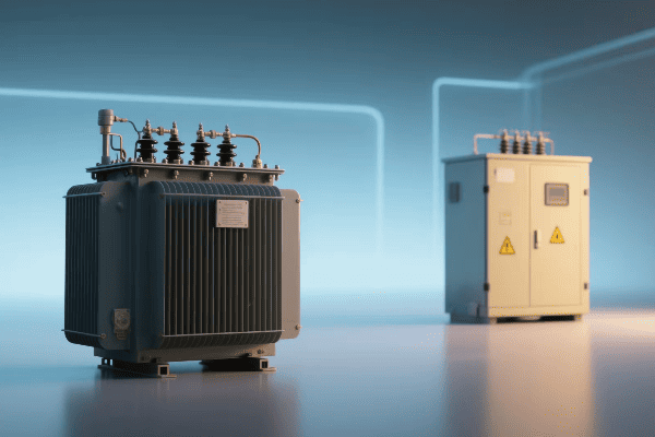
Electronic Power Transformers (EPTs) are revolutionizing power distribution systems. They combine traditional transformer functions with advanced power electronics, offering improved efficiency, power quality, and grid stability. EPTs are key components in the development of smart grids and modern power systems.
In this article, I’ll explain how Electronic Power Transformers are changing the game. As someone who’s worked with both traditional and electronic transformers, I’ve seen firsthand the impact of this technology.
How Do Electronic Power Transformers Differ from Traditional Transformers in Design and Function?
When I first encountered an Electronic Power Transformer, I was amazed by its complexity compared to traditional transformers. It was like comparing a smartphone to a landline.
Electronic Power Transformers differ from traditional transformers by incorporating power electronic converters. They use high-frequency switching to transform voltage, allowing for more compact designs and additional functionalities like active power flow control and harmonic mitigation.
Let’s dive deeper into the differences between EPTs and traditional transformers:
Core Design
The core design of EPTs is fundamentally different:
- Traditional Transformers: Use large iron cores for 50/60 Hz operation.
- EPTs: Employ smaller, high-frequency cores.
I remember working on a project where space was a major constraint. The compact design of the EPT allowed us to fit it into a space half the size of what a traditional transformer would have required.
Power Conversion Process
The power conversion process in EPTs is more complex:
| Stage | Traditional Transformer | Electronic Power Transformer |
|---|---|---|
| Input | AC directly to core | AC to DC conversion |
| Transformation | Magnetic field in core | High-frequency switching |
| Output | AC from secondary winding | DC to AC conversion |
This multi-stage conversion in EPTs allows for greater control over the output. In one project, we were able to maintain a stable output voltage despite significant input fluctuations, something that would have been challenging with a traditional transformer.
Frequency Operation
The frequency operation is a key differentiator:
- Traditional Transformers: Operate at grid frequency (50/60 Hz).
- EPTs: Use high-frequency switching (typically kHz range).
The high-frequency operation of EPTs results in smaller magnetic components. I’ve seen EPTs that are 30% lighter than their traditional counterparts with the same power rating.
Control Capabilities
EPTs offer superior control capabilities:
- Voltage Regulation: EPTs can provide precise voltage control.
- Power Factor Correction: They can adjust power factor in real-time.
- Harmonic Mitigation: EPTs can actively filter out harmonics.
In a recent industrial project, we used an EPT to solve both voltage regulation and harmonic issues that were plaguing the client’s sensitive equipment. It was like killing two birds with one stone.
Fault Handling
Fault handling is another area where EPTs shine:
- Traditional Transformers: Rely on external protection devices.
- EPTs: Can limit fault currents internally.
I once worked on a grid upgrade where the increased fault current levels were a major concern. By using EPTs, we were able to limit fault currents without additional equipment, simplifying the overall system design.
What Are the Key Advantages of Electronic Power Transformers in Smart Grid Applications?
Smart grids are the future of power distribution, and Electronic Power Transformers are playing a crucial role. I’ve seen firsthand how EPTs can transform a traditional grid into a smart, responsive system.
Electronic Power Transformers offer several key advantages in smart grid applications. These include real-time voltage regulation, power flow control, enhanced communication capabilities, and improved power quality. EPTs enable more efficient integration of renewable energy sources and support advanced grid management functions.
Let’s explore the advantages of EPTs in smart grid applications:
Real-Time Voltage Regulation
EPTs excel at voltage regulation:
- Traditional Transformers: Use tap changers, slow response.
- EPTs: Provide instantaneous voltage adjustment.
I once worked on a project integrating a large solar farm into the grid. The EPTs we used could adjust voltage in milliseconds, compensating for the rapid fluctuations in solar output.
Power Flow Control
EPTs offer unprecedented control over power flow:
| Aspect | Traditional Transformer | Electronic Power Transformer |
|---|---|---|
| Active Power | No control | Can control direction and magnitude |
| Reactive Power | Limited control via tap changers | Full four-quadrant control |
This level of control is game-changing. In a recent microgrid project, we used EPTs to balance loads between different renewable sources and storage systems, optimizing the overall system efficiency.
Enhanced Communication
EPTs are designed for the digital age:
- Data Collection: EPTs can gather detailed operational data.
- Network Integration: They can easily integrate with SCADA systems.
- Remote Control: EPTs allow for remote operation and adjustment.
I remember a utility project where the ability to remotely adjust EPT settings saved countless truck rolls, significantly reducing operational costs.
Improved Power Quality
Power quality improvement is a major advantage of EPTs:
- Harmonic Mitigation: EPTs can actively filter out harmonics.
- Voltage Balancing: They can balance voltages in three-phase systems.
- Flicker Reduction: EPTs can mitigate voltage flicker.
In an industrial park project, the installation of EPTs resolved long-standing power quality issues that had been affecting sensitive manufacturing processes.
Renewable Energy Integration
EPTs facilitate the integration of renewable energy sources:
- Voltage Support: They can provide voltage support for intermittent sources.
- Frequency Regulation: EPTs can help maintain grid frequency.
- Fault Ride-Through: They enhance the grid’s ability to handle faults.
I’ve worked on several wind farm integration projects where EPTs were crucial in meeting grid code requirements, allowing for higher penetration of wind power.
How Do Electronic Power Transformers Enhance Power Quality and System Reliability?
Power quality and system reliability are critical in our increasingly digital world. I’ve seen how poor power quality can wreak havoc on sensitive equipment and how unreliable power can cost businesses millions.
Electronic Power Transformers enhance power quality and system reliability through active voltage regulation, harmonic mitigation, and fault current limiting. They provide rapid response to power disturbances, maintain stable voltage profiles, and improve overall grid resilience.
Let’s delve into how EPTs enhance power quality and system reliability:
Active Voltage Regulation
EPTs offer superior voltage regulation:
- Fast Response: Can adjust voltage in cycles rather than seconds.
- Wide Range: Typically can regulate voltage ±10% or more.
- Independence: Each phase can be regulated independently.
I once worked on a project in an area with frequent voltage sags. The EPTs we installed maintained a stable voltage profile, protecting sensitive industrial equipment from damage and downtime.
Harmonic Mitigation
Harmonics are a growing concern in modern power systems:
| Harmonic Order | Traditional Transformer | Electronic Power Transformer |
|---|---|---|
| Low Order | Passive filtering | Active cancellation |
| High Order | Limited mitigation | Effective reduction |
In a data center project, the EPTs we used reduced total harmonic distortion from over 8% to less than 3%, significantly improving the efficiency and reliability of the IT equipment.
Fault Current Limiting
EPTs can actively limit fault currents:
- Fast Detection: EPTs can detect faults in less than a millisecond.
- Active Limiting: They can reduce fault current magnitude.
- Coordination: This feature simplifies protection system design.
I remember a grid upgrade project where the increased fault levels would have required extensive switchgear replacements. By using EPTs with fault current limiting capabilities, we avoided these costly upgrades.
Power Factor Correction
EPTs can dynamically correct power factor:
- Real-Time Adjustment: Can respond to changing load conditions.
- Full Range: Can operate in all four quadrants of P-Q plane.
- Localized Correction: Reduces the need for central compensation.
In an industrial facility project, the EPTs’ power factor correction feature eliminated the need for separate capacitor banks, simplifying the system and improving reliability.
Voltage Balancing
Three-phase voltage balancing is another key feature:
- Phase-Independent Control: Each phase can be regulated separately.
- Load Balancing: Can help balance uneven loads across phases.
- Negative Sequence Mitigation: Reduces issues from unbalanced conditions.
I’ve seen EPTs solve voltage balancing issues in areas with high concentrations of single-phase loads, improving overall system efficiency and reducing equipment stress.
What Role Do Power Electronics Play in the Operation of Electronic Power Transformers?
Power electronics are the heart of Electronic Power Transformers. As someone who’s worked extensively with both traditional transformers and EPTs, I can say that power electronics are what give EPTs their "super powers."
Power electronics play a crucial role in Electronic Power Transformers. They enable high-frequency power conversion, allowing for smaller magnetic components. Power electronic converters provide precise control over voltage, current, and power flow, enabling advanced features like active filtering and fault current limiting.

Let’s explore the role of power electronics in EPTs:
AC-DC-AC Conversion
The core function of power electronics in EPTs is AC-DC-AC conversion:
- Rectification: Converts input AC to DC.
- DC Link: Provides a stable DC voltage.
- Inversion: Converts DC back to AC at the desired voltage and frequency.
I remember working on an EPT design where this conversion process allowed us to completely isolate the input and output, providing superior protection against grid disturbances.
High-Frequency Operation
Power electronics enable high-frequency operation:
| Aspect | Traditional Transformer | Electronic Power Transformer |
|---|---|---|
| Operating Frequency | 50/60 Hz | kHz range |
| Core Size | Large | Significantly smaller |
| Weight | Heavy | Much lighter |
In a recent project, the high-frequency operation allowed us to reduce the transformer’s weight by 40%, making installation in a space-constrained urban substation much easier.
Advanced Control Algorithms
Power electronics in EPTs run sophisticated control algorithms:
- Voltage Regulation: Maintains stable output voltage.
- Current Control: Manages current flow and limits faults.
- Power Flow Control: Directs active and reactive power flow.
I’ve implemented control algorithms that allow EPTs to respond to grid conditions in milliseconds, something unthinkable with traditional transformers.
Harmonic Compensation
Power electronics enable active harmonic compensation:
- Harmonic Detection: Identifies harmonic components in real-time.
- Cancellation: Generates opposing harmonics to cancel out distortions.
- Adaptive Control: Adjusts to changing harmonic profiles.
In an industrial park project, the EPTs’ harmonic compensation feature eliminated the need for separate harmonic filters, simplifying the system and reducing costs.
Fault Current Limiting
Power electronics provide fault current limiting capabilities:
- Fast Detection: Identifies fault conditions rapidly.
- Current Limiting: Actively restricts fault current magnitude.
- Coordination: Works with existing protection systems.
I’ve seen EPTs limit fault currents to levels that existing switchgear could handle, avoiding costly equipment upgrades in grid expansion projects.
How Are Electronic Power Transformers Addressing Energy Efficiency and Environmental Concerns?
Energy efficiency and environmental concerns are at the forefront of power system design today. I’ve seen a growing demand for solutions that not only perform well but also minimize environmental impact.
Electronic Power Transformers address energy efficiency and environmental concerns through reduced losses, optimized operation, and support for renewable energy integration. They enable more efficient power flow, reduce the need for additional power quality equipment, and can be designed with environmentally friendly materials.
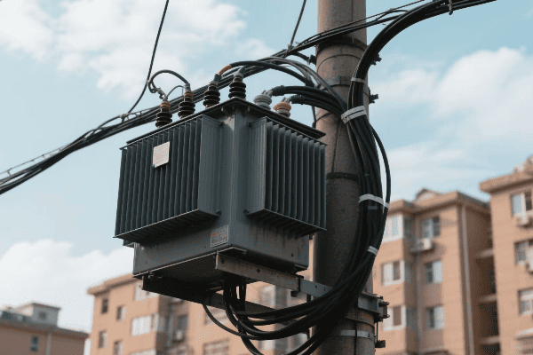
Let’s explore how EPTs are tackling these important issues:
Reduced Losses
EPTs can significantly reduce energy losses:
- No-Load Losses: Smaller core reduces iron losses.
- Load Losses: Advanced semiconductors minimize conduction losses.
- Overall Efficiency: Can exceed 99% in some designs.
I worked on a project replacing traditional transformers with EPTs in a large commercial building. The energy savings were impressive, with overall losses reduced by more than 20%.
Optimized Operation
EPTs can optimize their operation for maximum efficiency:
| Aspect | Traditional Transformer | Electronic Power Transformer |
|---|---|---|
| Load Adaptation | Fixed design | Can adapt to load conditions |
| Partial Load Efficiency | Lower | Maintains high efficiency |
| Power Factor | No control | Can optimize for unity power factor |
In a recent microgrid project, the EPTs’ ability to adapt to varying load conditions resulted in consistently high efficiency, even during low-load periods.
Renewable Energy Integration
EPTs facilitate the integration of renewable energy sources:
- Voltage Support: Helps stabilize voltage with intermittent sources.
- Frequency Regulation: Assists in maintaining grid frequency.
- Bi-Directional Power Flow: Supports energy storage integration.
I’ve worked on several solar farm projects where EPTs were crucial in meeting grid connection requirements, allowing for higher penetration of solar energy.
Reduced Material Usage
EPTs often use less material than traditional transformers:
- Smaller Core: High-frequency operation allows for smaller magnetic components.
- Less Copper: Compact design reduces the amount of copper needed.
- Reduced Oil: Some designs eliminate the need for large oil volumes.
In a recent substation upgrade project, the compact EPTs allowed us to increase capacity without expanding the substation footprint, preserving valuable urban land.
Environmental-Friendly Materials
EPTs can be designed with more environmentally friendly materials:
- Dry-Type Designs: Eliminate the need for insulating oil.
- Biodegradable Fluids: When liquid cooling is needed, bio-based fluids can be used.
- Recyclable Components: Power electronic components are often more recyclable than traditional transformer materials.
I remember a project where the client’s environmental concerns led us to choose EPTs with biodegradable cooling fluids, significantly reducing the environmental risk.
Conclusion
Electronic Power Transformers are revolutionizing power distribution systems. They offer improved efficiency, power quality, and grid stability. As smart grids evolve, EPTs will play a crucial role in creating more reliable, efficient, and environmentally friendly power systems.
Have you ever wondered how electrical engineers choose the right transformer for a job? The secret lies in understanding power transformer ratings.
Power transformer ratings are essential specifications that define a transformer’s operational limits and performance characteristics. These ratings include voltage, current, power capacity (kVA), impedance, efficiency, and temperature rise. Understanding these ratings is crucial for proper transformer selection and operation.
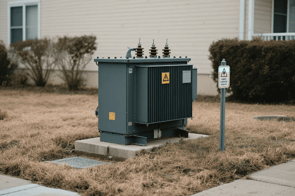
In this article, I’ll break down the complexities of power transformer ratings. As an electrical engineer with years of experience in the field, I’ve learned the importance of these ratings the hard way.
What Are the Key Parameters in Power Transformer Ratings and Their Significance?
When I first started working with transformers, I was overwhelmed by the number of ratings on the nameplate. But I quickly learned how crucial each one is.
The key parameters in power transformer ratings include voltage, current, kVA, impedance, efficiency, and temperature rise. These ratings define the transformer’s capacity, operational limits, and performance characteristics. They are essential for proper transformer selection, installation, and operation.
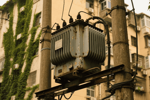
Let’s dive deeper into these key parameters and their significance:
Voltage Rating
Voltage rating is perhaps the most obvious parameter:
- Primary Voltage: The input voltage the transformer is designed to receive.
- Secondary Voltage: The output voltage the transformer delivers.
- BIL (Basic Impulse Level): The transformer’s ability to withstand voltage surges.
I once worked on a project where a transformer was incorrectly specified with a lower BIL rating. During a lightning storm, the transformer failed, causing a major outage. It taught me the importance of considering all aspects of the voltage rating.
Current Rating
Current ratings are equally important:
| Rating | Description | Significance |
|---|---|---|
| Primary Current | Maximum current on the input side | Determines wire size and protection |
| Secondary Current | Maximum current on the output side | Affects load capacity and protection |
| Short Circuit Current | Maximum current during a fault | Critical for protection system design |
I remember a case where a transformer was consistently tripping its protection due to high inrush current. By understanding the current ratings, we were able to adjust the protection settings without compromising safety.
Power Rating (kVA)
The kVA rating is the transformer’s capacity:
- Continuous kVA: The load the transformer can handle indefinitely.
- Peak kVA: Short-term overload capacity.
- Ambient Temperature: kVA rating is typically at 30°C ambient.
Understanding kVA rating is crucial. I once had to explain to a client why their 1000 kVA transformer couldn’t power a 1200 kW load continuously. It’s not just about the numbers, but also about the conditions and duration of the load.
Impedance
Transformer impedance affects system performance:
- Percentage Impedance: Typically 5-7% for distribution transformers.
- Effect on Fault Current: Higher impedance limits fault current.
- Parallel Operation: Impedance matching is crucial for load sharing.
I’ve seen the impact of mismatched impedances in parallel transformers. The uneven load sharing can lead to overheating and reduced efficiency. Proper understanding of impedance ratings is key to avoiding these issues.
Efficiency Rating
Efficiency is becoming increasingly important:
- No-Load Losses: Core losses present even when the transformer is energized but not loaded.
- Load Losses: Copper losses that increase with load.
- Total Losses: Sum of no-load and load losses at rated load.
I’ve been involved in projects where the focus was on selecting high-efficiency transformers. The initial cost was higher, but the energy savings over the transformer’s lifetime more than justified the investment.
How Do Voltage and Current Ratings Affect Power Transformer Selection and Operation?
Voltage and current ratings are the foundation of transformer selection. I’ve seen projects go wrong when these ratings weren’t properly considered.
Voltage and current ratings determine a transformer’s compatibility with the power system and load requirements. They affect the transformer’s insulation design, winding configuration, and protection systems. Proper selection based on these ratings ensures safe and efficient operation.
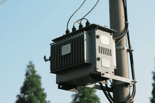
Let’s explore how voltage and current ratings impact transformer selection and operation:
Voltage Rating Considerations
Voltage ratings have a significant impact on transformer design and operation:
- Insulation Design: Higher voltage ratings require more robust insulation.
- Tap Changers: Voltage ratings determine the need for and range of tap changers.
- System Compatibility: Transformers must match system voltage levels.
I once worked on a project where a transformer was incorrectly specified with a lower voltage rating. It led to insulation breakdown and failure within months of installation. It was a costly lesson in the importance of proper voltage rating selection.
Current Rating Implications
Current ratings affect various aspects of transformer design:
| Aspect | Impact of Current Rating |
|---|---|
| Winding Design | Determines conductor size and number of turns |
| Thermal Management | Affects cooling system design |
| Protection Systems | Influences selection of circuit breakers and fuses |
I remember a case where a transformer was consistently overheating. Upon investigation, we found that the actual load current was exceeding the rated current. It highlighted the importance of not just selecting the right ratings, but also ensuring the load stays within those limits.
Voltage Regulation
The interaction of voltage and current ratings affects voltage regulation:
- Definition: The change in secondary voltage from no-load to full-load.
- Importance: Affects the quality of power delivered to the load.
- Calculation: Depends on both voltage and current ratings, as well as impedance.
I’ve worked on projects where tight voltage regulation was crucial, such as in semiconductor manufacturing facilities. Understanding how voltage and current ratings interact to affect regulation was key to selecting the right transformer.
Short Circuit Withstand Capability
Current ratings, particularly short-circuit current ratings, are critical for safety:
- Mechanical Strength: Windings must withstand electromagnetic forces during faults.
- Thermal Capability: Transformer must handle heat generated during short-circuits.
- Protection Coordination: Influences the design of the entire protection system.
I once investigated a transformer failure that occurred during a system fault. The transformer’s short-circuit withstand capability was inadequate for the actual fault levels in the system. It underscored the importance of considering not just normal operating conditions, but also fault conditions when selecting transformers.
Inrush Current Considerations
Voltage ratings play a role in inrush current phenomena:
- Cause: Energizing a transformer can cause a large inrush of current.
- Magnitude: Can be 10-15 times the rated current.
- Mitigation: Proper selection of voltage rating and core design can help reduce inrush current.
I’ve been involved in projects where we had to implement special switching schemes to mitigate inrush current issues. Understanding the relationship between voltage ratings and inrush current was crucial in developing these solutions.
Understanding kVA Ratings: How Does It Impact Transformer Capacity and Efficiency?
The kVA rating of a transformer is often misunderstood. I’ve seen engineers and technicians alike make mistakes in interpreting this crucial rating.
The kVA (kilovolt-ampere) rating represents a transformer’s power handling capacity. It directly impacts the transformer’s ability to supply load and its efficiency under various loading conditions. Understanding kVA ratings is crucial for proper sizing and operation of transformers.
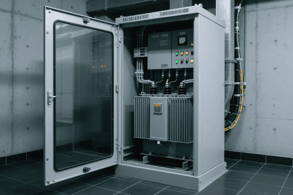
Let’s delve into how kVA ratings affect transformer capacity and efficiency:
Defining kVA Rating
First, let’s clarify what kVA really means:
- Definition: Apparent power handling capacity of the transformer.
- Calculation: kVA = Voltage (kV) × Current (A) for single-phase transformers.
- Three-Phase: For three-phase transformers, multiply by √3.
I remember explaining this to a client who couldn’t understand why their 1000 kVA transformer couldn’t handle a 1000 kW load at 0.8 power factor. It was a great opportunity to explain the difference between apparent and real power.
Impact on Transformer Capacity
The kVA rating directly determines the transformer’s load capacity:
| Aspect | Relation to kVA Rating |
|---|---|
| Maximum Load | Should not exceed kVA rating for continuous operation |
| Overload Capability | Short-term overloads may be possible, but reduce transformer life |
| Voltage-Current Relationship | For a given kVA, increasing voltage decreases available current |
I once worked on a project where a factory was expanding its production line. We had to carefully calculate the new total load to determine if the existing transformer’s kVA rating was sufficient or if an upgrade was necessary.
Efficiency and Loading
The kVA rating also affects transformer efficiency:
- No-Load Losses: Present regardless of load, but a larger proportion of total losses at light loads.
- Load Losses: Increase with the square of the load current.
- Optimal Efficiency: Typically occurs at 40-50% of rated kVA.
I’ve been involved in energy efficiency projects where we analyzed transformer loading patterns. In one case, we found that replacing several underutilized transformers with a single, appropriately sized unit significantly improved overall efficiency.
Temperature Rise and kVA Rating
The kVA rating is closely tied to temperature rise:
- Rated kVA: Based on a specific temperature rise (usually 65°C) above ambient.
- Overloading: Increases temperature rise, potentially degrading insulation.
- Ambient Temperature: Higher ambient temperatures reduce the effective kVA capacity.
I remember a project in a hot climate where we had to de-rate transformers due to high ambient temperatures. Understanding the relationship between kVA, temperature rise, and ambient conditions was crucial for ensuring reliable operation.
Sizing Considerations
Proper sizing based on kVA rating is crucial:
- Undersizing: Leads to overheating and reduced transformer life.
- Oversizing: Results in higher initial costs and potentially lower efficiency.
- Future Growth: Consider potential load increases when selecting kVA rating.
I’ve seen the consequences of both undersizing and oversizing. In one case, an undersized transformer failed prematurely, causing significant downtime. In another, an oversized transformer operated inefficiently for years, wasting energy. Proper sizing based on a thorough understanding of kVA ratings is key to avoiding these issues.
What Role Do Impedance and Efficiency Ratings Play in Power Transformer Performance?
Impedance and efficiency ratings might not be the first things you look at on a transformer nameplate, but they’re crucial for system performance. I’ve learned their importance through years of designing and troubleshooting power systems.
Impedance ratings affect fault current levels, voltage regulation, and parallel operation of transformers. Efficiency ratings indicate the transformer’s energy losses. Together, these ratings significantly impact the overall performance and operating costs of power transformers.
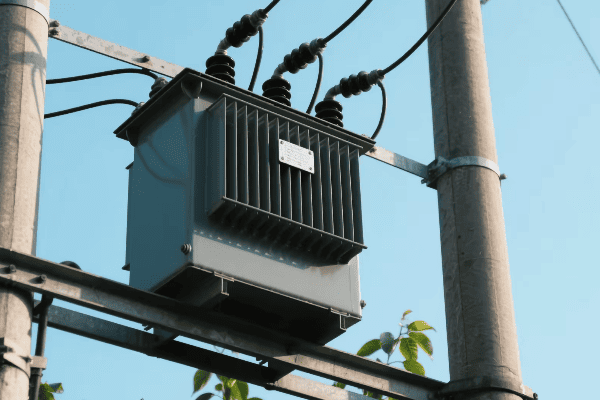
Let’s explore the roles of impedance and efficiency ratings in more detail:
Understanding Impedance Ratings
Transformer impedance is a key parameter:
- Definition: The total opposition to current flow in a transformer, expressed as a percentage.
- Typical Values: 5-7% for distribution transformers, can be higher for larger units.
- Calculation: Based on the voltage drop across the transformer at full load.
I remember a project where parallel transformers were not sharing load equally. It turned out their impedances were mismatched. This experience taught me the practical importance of impedance ratings.
Impact of Impedance on System Performance
Impedance affects several aspects of system performance:
| Aspect | Impact of Impedance |
|---|---|
| Fault Current | Higher impedance limits fault current |
| Voltage Regulation | Higher impedance increases voltage drop under load |
| Parallel Operation | Transformers must have matching impedances for proper load sharing |
I once worked on a system upgrade where we needed to limit fault currents. By selecting transformers with slightly higher impedance, we were able to achieve this without additional equipment, saving cost and space.
Efficiency Ratings and Losses
Efficiency ratings are becoming increasingly important:
- No-Load Losses: Present whenever the transformer is energized, regardless of load.
- Load Losses: Increase with the square of the load current.
- Total Losses: The sum of no-load and load losses at rated load.
I’ve been involved in several projects focusing on energy efficiency. In one case, replacing old transformers with high-efficiency units resulted in significant energy savings, with a payback period of just a few years.
Efficiency Standards
Transformer efficiency standards are becoming more stringent:
- DOE Standards: In the US, the Department of Energy sets minimum efficiency levels.
- EU Ecodesign: Similar standards exist in Europe.
- Voluntary Standards: Some utilities have even higher efficiency requirements.
I’ve had to stay up-to-date with these evolving standards. In a recent project, we had to ensure our transformer designs met not only current standards but also anticipated future requirements.
Trade-offs Between Impedance and Efficiency
There’s often a balance to strike between impedance and efficiency:
- Lower Impedance: Generally more efficient but allows higher fault currents.
- Higher Impedance: Limits fault currents but may have higher losses.
- Design Optimization: Modern designs aim to balance these factors.
I remember a challenging project where we needed to limit fault currents while maintaining high efficiency. We ended up using a combination of transformer design and external reactors to achieve the desired performance.
Economic Considerations
Both impedance and efficiency ratings have economic implications:
- Initial Cost: Higher efficiency transformers typically have a higher upfront cost.
- Operating Cost: More efficient transformers have lower energy losses and operating costs.
- Lifecycle Cost: The total cost over the transformer’s life, including purchase and operating costs.
I’ve helped clients perform lifecycle cost analyses to justify investments in high-efficiency transformers. In most cases, the energy savings over the transformer’s life far outweighed the higher initial cost.
How Are Temperature Rise and Insulation Class Related to Power Transformer Ratings?
Temperature rise and insulation class are critical aspects of transformer ratings that I’ve found are often overlooked. Yet, they play a crucial role in transformer longevity and performance.
Temperature rise ratings indicate the maximum allowable temperature increase under full load. Insulation class defines the maximum operating temperature the insulation can withstand. Together, these ratings determine the transformer’s loading capacity and expected lifespan.

Let’s explore the relationship between temperature rise, insulation class, and transformer ratings:
Understanding Temperature Rise
Temperature rise is a key rating:
- Definition: The increase in winding temperature above ambient when the transformer is at full load.
- Standard Ratings: Typically 55°C, 65°C, or 80°C rise above a 30°C ambient.
- Measurement: Average winding temperature rise, measured by resistance method.
I once worked on a project where a transformer was consistently running hot. By investigating the temperature rise rating and actual operating conditions, we discovered that the ambient temperature was higher than assumed in the rating, leading to overheating.
Insulation Class
Insulation class is closely related to temperature rise:
| Insulation Class | Maximum Temperature |
|---|---|
| Class A | 105°C |
| Class B | 130°C |
| Class F | 155°C |
| Class H | 180°C |
I remember a case where a client wanted to upgrade their process but was constrained by their existing transformer. By switching to a transformer with a higher insulation class, we were able to accommodate the increased load without replacing the entire unit.
Relationship to Loading Capacity
Temperature rise and insulation class directly affect loading capacity:
- Continuous Loading: Determined by rated temperature rise.
- Overloading: Possible for short durations, but accelerates insulation aging.
- Ambient Temperature: Higher ambient reduces available loading capacity.
I’ve been involved in projects where we had to carefully calculate allowable loading under various ambient conditions. It’s not just about the nameplate rating; understanding the interplay of temperature rise, insulation class, and ambient conditions is crucial.
Impact on Transformer Lifespan
These ratings significantly affect transformer longevity:
- Insulation Aging: Accelerates at higher temperatures.
- Rule of Thumb: Insulation life halves for every 10°C increase above rated temperature.
- Cumulative Effect: Even short periods of overheating can significantly reduce transformer life.
I once investigated a premature transformer failure. We found that frequent overloading had caused cumulative damage to the insulation, even though individual overloads seemed minor. It highlighted the importance of respecting temperature limits.
Cooling Systems and Temperature Rise
Cooling systems are designed based on temperature rise ratings:
- ONAN (Oil Natural Air Natural): Simplest cooling method, suitable for lower temperature rise ratings.
- ONAF (Oil Natural Air Forced): Fans are added to increase cooling capacity.
- OFAF (Oil Forced Air Forced): Both oil pumps and fans are used for more effective cooling.
I’ve worked on projects where upgrading the cooling system allowed for increased loading capacity. In one case, adding fans to an ONAN transformer effectively turned it into an ONAF unit, increasing its capacity by about 25%.
Environmental Considerations
Temperature rise and insulation class ratings also have environmental implications:
- Energy Efficiency: Lower temperature rise often correlates with higher efficiency.
- Cooling Requirements: Higher temperature rise may require more extensive cooling systems.
- Insulation Materials: Higher insulation classes may use different materials with varying environmental impacts.
In a recent project, we opted for a transformer with a lower temperature rise. While it was more expensive initially, it reduced cooling requirements and improved overall system efficiency, aligning with the client’s sustainability goals.
Monitoring and Maintenance
Understanding these ratings is crucial for proper monitoring and maintenance:
- Temperature Monitoring: Critical for detecting abnormal operating conditions.
- Insulation Testing: Regular testing helps track insulation degradation over time.
- Cooling System Maintenance: Ensuring proper operation of cooling systems is vital for maintaining rated temperature rise.
I’ve implemented monitoring systems that track winding temperatures in real-time. In one case, this early warning system allowed us to detect a developing fault before it led to a catastrophic failure.
Conclusion
Understanding power transformer ratings is crucial for electrical engineers. Voltage, current, kVA, impedance, efficiency, temperature rise, and insulation class all play vital roles in transformer selection, operation, and maintenance. Proper application of this knowledge ensures reliable and efficient power systems.
Have you ever wondered how electricity travels across vast distances? The answer lies in large power transformers, but many people don’t know their importance.
Large power transformers are critical components in electrical grids. They enable efficient long-distance power transmission by stepping up voltage for transmission and stepping it down for distribution. These transformers are essential for maintaining grid stability and reliability.

In this article, I’ll share my insights on large power transformers. I’ve worked with these giants for years, and I’m excited to explain their role in our power systems.
What Defines a Large Power Transformer and Its Unique Characteristics?
When I first saw a large power transformer, I was amazed by its size. These aren’t your typical transformers you see on utility poles.
Large power transformers are defined by their high capacity, typically above 100 MVA, and their ability to handle extra high voltages, often 345 kV and above. They are massive, custom-built machines designed for specific grid locations and requirements.
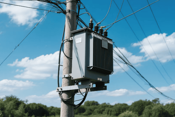
Let’s dive deeper into what makes large power transformers unique:
Size and Capacity
Large power transformers are truly massive:
- Physical Size: They can be as large as a house and weigh hundreds of tons.
- Capacity: Typically range from 100 MVA to over 1,000 MVA.
- Voltage Levels: Can handle voltages from 345 kV to 765 kV or even higher.
I once worked on a project installing a 500 MVA transformer. The logistics of transporting and installing such a massive piece of equipment were incredibly complex.
Custom Design
Unlike smaller transformers, large power transformers are not off-the-shelf products:
| Aspect | Description |
|---|---|
| Design | Tailored to specific grid location and requirements |
| Manufacturing | Built to order, often taking months to produce |
| Installation | Requires specialized equipment and expertise |
Each large power transformer is unique. I remember a project where we had to design a transformer to fit in a tight substation space while meeting specific performance requirements. It was like solving a complex puzzle.
Cooling Systems
Large power transformers require advanced cooling systems:
- Oil Cooling: Most use mineral oil for insulation and cooling.
- Forced Oil and Air Cooling: Fans and pumps circulate oil and air.
- Water Cooling: Some use water-cooled radiators for additional cooling.
The cooling system design is crucial. I once worked on optimizing a cooling system for a transformer in a hot climate. We had to ensure it could handle peak loads even on the hottest days.
On-Load Tap Changers
Large power transformers often include sophisticated on-load tap changers:
- Function: Adjust voltage ratios without interrupting power flow.
- Complexity: More complex than those in smaller transformers.
- Importance: Critical for maintaining grid voltage stability.
I’ve seen how crucial these tap changers are. In one project, we implemented an advanced tap changer control system that significantly improved voltage regulation across a large service area.
How Do Large Power Transformers Contribute to Efficient Energy Transmission in Electrical Grids?
Efficient energy transmission is crucial for our power grids. Large power transformers play a key role in this process. I’ve seen firsthand how these transformers can make or break a grid’s efficiency.
Large power transformers enable efficient energy transmission by stepping up voltage for long-distance power transfer. This reduces transmission losses and allows for bulk power transfer across great distances. They also step down voltage at substations for local distribution.
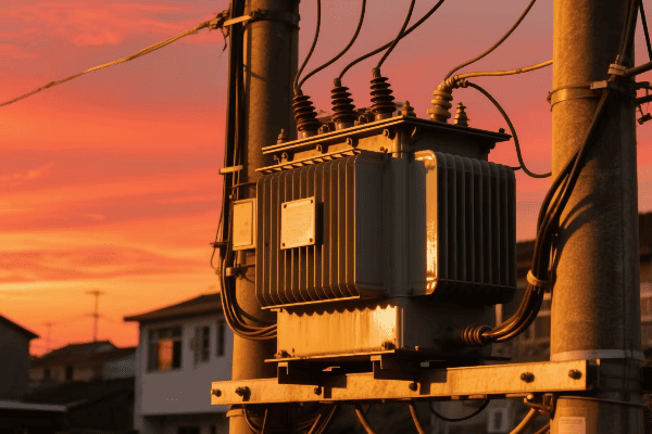
Let’s explore how large power transformers contribute to efficient energy transmission:
Voltage Step-Up for Transmission
Large power transformers at power plants step up voltage for transmission:
- Typical Step-Up: From generator voltage (15-25 kV) to transmission voltage (345-765 kV).
- Purpose: Higher voltage means lower current for the same power, reducing losses.
- Efficiency: Enables power transfer over hundreds of miles with minimal losses.
I once worked on a project upgrading a power plant’s main step-up transformer. The new transformer increased the plant’s transmission capacity by 20%, allowing it to serve a larger area more efficiently.
Voltage Step-Down for Distribution
At substations, large transformers step down voltage for distribution:
| Input Voltage | Output Voltage | Purpose |
|---|---|---|
| 345-765 kV | 115-138 kV | Subtransmission |
| 115-138 kV | 69 kV | Large industrial |
| 69 kV | 12-34.5 kV | Local distribution |
This step-down process is crucial. I’ve designed substation layouts to optimize the placement of these transformers, ensuring efficient power flow to different service areas.
Bulk Power Transfer
Large power transformers enable bulk power transfer between regions:
- Interconnections: Allow power exchange between different grid systems.
- Load Balancing: Enable power transfer from areas of excess to areas of need.
- Renewable Integration: Facilitate transfer of power from remote renewable sources.
I’ve been involved in projects connecting large wind farms to the grid. The ability to transfer bulk power over long distances was crucial for making these renewable projects viable.
Loss Reduction
Large power transformers are designed for high efficiency:
- Core Design: Advanced materials and designs minimize core losses.
- Winding Design: Optimized for minimal resistance and eddy current losses.
- Cooling Systems: Efficient cooling reduces losses due to heating.
In one project, we replaced an old transformer with a modern, high-efficiency model. The reduction in losses was significant, saving the utility millions in energy costs over the transformer’s lifetime.
What Are the Critical Design Features of Large Power Transformers for Grid Stability?
Grid stability is a top priority in power system design. Large power transformers play a crucial role in maintaining this stability. I’ve spent a lot of time optimizing transformer designs for grid stability.
Critical design features of large power transformers for grid stability include robust mechanical construction, advanced voltage regulation systems, efficient cooling mechanisms, and high short-circuit strength. These features ensure the transformer can handle system disturbances and maintain reliable operation.
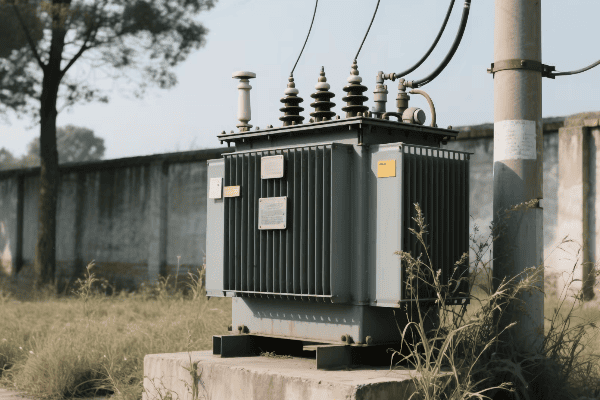
Let’s explore these critical design features in detail:
Robust Mechanical Construction
Large power transformers must withstand various stresses:
- Short-Circuit Forces: Massive electromagnetic forces during faults.
- Seismic Activity: Must remain operational even during earthquakes.
- Transportation Stresses: Designed to handle shocks during transport and installation.
I once worked on a transformer design for a seismically active area. We had to use advanced 3D modeling to ensure the transformer could withstand potential earthquakes without losing its alignment or functionality.
Advanced Voltage Regulation
Voltage regulation is crucial for grid stability:
| Feature | Function | Benefit |
|---|---|---|
| On-Load Tap Changers | Adjust voltage ratio during operation | Maintain stable output voltage |
| Automatic Voltage Control | Respond to grid voltage fluctuations | Prevent voltage sags or swells |
| Fast Response Time | Quick adjustment to sudden load changes | Improve transient stability |
I’ve implemented advanced voltage control systems that can respond to grid fluctuations in milliseconds. This rapid response is crucial for maintaining stability, especially with the increasing integration of intermittent renewable sources.
Efficient Cooling Mechanisms
Proper cooling is essential for stable operation:
- Oil Directed/Oil Forced (ODOF): Pumps circulate oil through cooling radiators.
- Oil Directed/Air Forced (ODAF): Fans enhance cooling of oil radiators.
- Water-Cooled Systems: For very large transformers or special applications.
I remember a project where we had to design a cooling system for a transformer in an extremely hot climate. We ended up using a combination of ODAF and water cooling to ensure the transformer could handle peak loads even on the hottest days.
High Short-Circuit Strength
Transformers must withstand short-circuit events:
- Winding Design: Special bracing and supports to handle electromagnetic forces.
- Insulation System: Designed to withstand electrical and mechanical stresses.
- Core Construction: Robust core clamping to prevent movement during faults.
I’ve been involved in transformer failure investigations where inadequate short-circuit strength was the root cause. These experiences have taught me the importance of rigorous design and testing in this area.
Impedance Control
Transformer impedance affects system stability:
- Impedance Matching: Designed to match system requirements.
- Parallel Operation: Impedance affects load sharing between transformers.
- Fault Current Limitation: Higher impedance can help limit fault currents.
Choosing the right impedance is a balancing act. I’ve worked on projects where we had to carefully select transformer impedances to ensure stable parallel operation of multiple units while also considering fault current levels.
How Are Large Power Transformers Integrated into Smart Grid Technologies?
Smart grid technologies are revolutionizing our power systems. Large power transformers are being adapted to fit into this new, intelligent grid. I’ve been involved in several projects integrating these transformers with smart grid systems.
Large power transformers are integrated into smart grid technologies through advanced monitoring systems, real-time data analytics, and automated control mechanisms. This integration allows for improved asset management, predictive maintenance, and dynamic grid optimization.
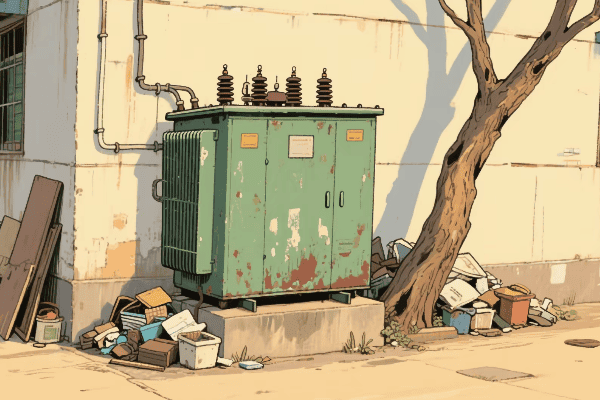
Let’s explore how large power transformers are becoming part of the smart grid:
Advanced Monitoring Systems
Modern large power transformers are equipped with various sensors:
- Temperature Sensors: Monitor oil and winding temperatures.
- Dissolved Gas Analysis (DGA): Detect fault gases in transformer oil.
- Partial Discharge Monitoring: Identify insulation weaknesses.
- Load Tap Changer Monitoring: Track tap changer performance.
I once worked on implementing a comprehensive monitoring system for a fleet of large transformers. The amount of data we could collect was impressive, giving us insights we never had before.
Real-Time Data Analytics
Smart grid integration involves processing transformer data in real-time:
| Data Type | Analysis | Benefit |
|---|---|---|
| Temperature Data | Thermal modeling | Optimize loading and cooling |
| DGA Data | Fault gas trend analysis | Early fault detection |
| Tap Changer Data | Operation pattern analysis | Predict maintenance needs |
| Loading Data | Dynamic rating calculation | Maximize transformer capacity |
I’ve seen how real-time analytics can make a difference. In one project, we were able to detect a developing fault months before it would have caused a failure, saving millions in potential outage costs.
Automated Control Mechanisms
Smart grids allow for automated transformer control:
- Dynamic Voltage Regulation: Automatic adjustment based on grid conditions.
- Cooling System Optimization: Intelligent control of cooling based on load and ambient conditions.
- Load Management: Coordinated control of multiple transformers for optimal power flow.
I’ve implemented automated control systems that can balance loads across multiple transformers in a substation, significantly improving overall efficiency and reliability.
Integration with SCADA Systems
Large transformers are integrated into broader grid management systems:
- Data Reporting: Regular status updates to control centers.
- Remote Control: Ability to adjust transformer settings from afar.
- Alarm Systems: Immediate notification of abnormal conditions.
I remember a project where we integrated transformer controls with a utility’s SCADA system. It gave operators unprecedented visibility and control over their transmission assets.
Cybersecurity Considerations
With increased connectivity comes the need for robust cybersecurity:
- Secure Communication Protocols: Encrypted data transmission.
- Access Control: Strict authentication for remote access.
- Regular Security Audits: Ensure ongoing protection against evolving threats.
Cybersecurity is a growing concern. I’ve worked on implementing secure communication systems for transformer monitoring, ensuring that the benefits of connectivity don’t come at the cost of vulnerability.
What Challenges and Solutions Exist in Maintaining Large Power Transformers for Grid Reliability?
Maintaining large power transformers is crucial for grid reliability. These massive machines face unique challenges. I’ve encountered many of these challenges in my career and worked on innovative solutions.
Challenges in maintaining large power transformers include aging infrastructure, increasing load demands, and the need for predictive maintenance. Solutions involve advanced monitoring technologies, life extension techniques, and strategic replacement planning to ensure continued grid reliability.

Let’s dive into the challenges and solutions for maintaining large power transformers:
Aging Infrastructure
Many large transformers are nearing the end of their designed life:
- Challenge: Increased risk of failure as transformers age.
- Solution: Life extension programs and condition-based maintenance.
I’ve worked on life extension projects for transformers over 40 years old. With proper maintenance and upgrades, we’ve been able to safely extend their service life by 15-20 years.
Increasing Load Demands
Modern grids often push transformers to their limits:
| Challenge | Solution | Benefits |
|---|---|---|
| Higher load stress | Dynamic rating systems | Maximize capacity safely |
| Overloading risks | Advanced cooling upgrades | Increase short-term overload capability |
| Harmonics from non-linear loads | Harmonic mitigation techniques | Reduce heating and extend life |
I once implemented a dynamic rating system for a critical transformer. It allowed the utility to safely increase its capacity by 15% during peak demand periods.
Predictive Maintenance
Moving from time-based to condition-based maintenance:
- Challenge: Predicting failures before they occur.
- Solution: Advanced monitoring and AI-based predictive analytics.
I’ve been involved in developing AI models that can predict transformer faults weeks or even months in advance. It’s amazing how much we can learn from the data these transformers generate.
Oil Management
Oil is crucial for insulation and cooling:
- Challenge: Oil degradation over time.
- Solution: Regular oil testing and advanced oil regeneration techniques.
I remember a project where we implemented an online oil purification system. It continuously cleaned the transformer oil, significantly extending the transformer’s life and improving its reliability.
Spare Part Management
Many large transformers are custom-built:
- Challenge: Long lead times for replacement parts.
- Solution: Strategic spare part inventory and 3D printing for certain components.
I’ve worked with utilities to develop spare part strategies. In one case, we used 3D printing to quickly produce a custom bushing adapter, avoiding a lengthy outage.
Environmental Concerns
Transformers can pose environmental risks:
- Challenge: Oil leaks and PCB contamination in older units.
- Solution: Containment systems and environmentally friendly insulating fluids.
I’ve been involved in projects replacing old oil with biodegradable ester fluids. It’s a great way to reduce environmental risk while also improving transformer cooling.
Workforce Expertise
Specialized knowledge is required for transformer maintenance:
- Challenge: Retiring workforce with years of experience.
- Solution: Knowledge transfer programs and augmented reality maintenance tools.
I’ve helped develop training programs using VR and AR technologies. These tools help new technicians gain experience safely and efficiently.
Conclusion
Large power transformers are critical for grid stability and efficiency. Understanding their design, integration with smart grids, and maintenance challenges is crucial for ensuring reliable power supply. Continuous innovation in this field is essential for our evolving energy needs.
Have you ever wondered how electricity travels from power plants to your home? The answer lies in power transformers, but many people don’t know how they work.
Power transformers are devices that transfer electrical energy between two circuits using electromagnetic induction. They change voltage levels without changing the frequency, allowing for efficient power transmission and distribution across long distances.
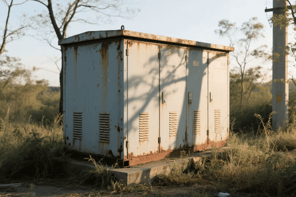
In this guide, I’ll break down the workings of power transformers. I’ve spent years in the power industry, and I’m excited to share my knowledge with you.
What Are the Basic Principles of Electromagnetic Induction in Power Transformers?
Electromagnetic induction might sound complex, but it’s the foundation of how power transformers work. I remember being fascinated by this concept when I first learned about it.
Electromagnetic induction in power transformers involves a changing magnetic field in one coil inducing a voltage in another coil. This principle allows transformers to transfer energy between circuits without direct electrical connection.
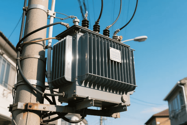
Let’s dive deeper into the principles of electromagnetic induction in power transformers:
Faraday’s Law of Induction
Faraday’s Law is the key to understanding how transformers work. It states that a changing magnetic field induces a voltage in a conductor. Here’s how it applies to transformers:
- Primary Coil: When AC current flows through this coil, it creates a changing magnetic field.
- Magnetic Core: This field is concentrated in the core.
- Secondary Coil: The changing field in the core induces a voltage in this coil.
I once explained this to a group of students using a simple experiment with two coils and a magnet. Their eyes lit up when they saw the meter move as I moved the magnet through one coil.
Mutual Induction
Mutual induction is the process where two coils interact through their magnetic fields. In a transformer:
| Primary Coil | Secondary Coil |
|---|---|
| Creates magnetic field | Experiences induced voltage |
| Receives input power | Delivers output power |
| Determines input current | Determines output voltage |
This interaction is what allows transformers to transfer energy between circuits without direct electrical contact.
Lenz’s Law
Lenz’s Law explains the direction of induced current in the secondary coil. It states that the induced current will create a magnetic field that opposes the change in the original field. This law ensures that:
- The induced voltage in the secondary coil has the correct polarity.
- Energy is conserved in the transformation process.
Understanding Lenz’s Law helped me grasp why transformers work the way they do, and why they’re so efficient at transferring energy.
How Do Primary and Secondary Windings Interact to Transfer Energy in a Power Transformer?
The interaction between primary and secondary windings is like a well-choreographed dance. It’s this interaction that makes power transformers so effective at energy transfer.
Primary and secondary windings in a power transformer interact through a shared magnetic field. The primary winding creates a changing magnetic flux, which induces a voltage in the secondary winding. This process transfers energy between the two circuits.

Let’s explore this interaction in more detail:
Primary Winding Function
The primary winding is where it all starts. Here’s what happens:
- AC Input: Alternating current from the power source enters the primary winding.
- Magnetic Field Generation: This current creates a changing magnetic field.
- Flux Linkage: The magnetic field links with the secondary winding through the core.
I remember working on a transformer design where we had to carefully calculate the number of turns in the primary winding to match the input voltage. It’s a crucial step in transformer design.
Secondary Winding Response
The secondary winding responds to the magnetic field from the primary:
- Induced Voltage: The changing magnetic field induces a voltage in the secondary winding.
- Current Flow: If a load is connected, current flows in the secondary circuit.
- Power Transfer: Electrical energy is effectively transferred from primary to secondary.
Turns Ratio and Voltage Transformation
The ratio of turns in the primary and secondary windings determines the voltage transformation:
| Turns Ratio | Voltage Transformation |
|---|---|
| Np > Ns | Step-down transformer |
| Np < Ns | Step-up transformer |
| Np = Ns | Isolation transformer |
Where Np is the number of primary turns and Ns is the number of secondary turns.
This relationship is crucial. I once worked on a project where we needed to step up voltage for long-distance transmission. By carefully designing the turns ratio, we were able to achieve the exact voltage increase needed.
Energy Conservation
Despite the voltage change, energy is conserved in an ideal transformer:
- Power In = Power Out
- Vp Ip = Vs Is
Where Vp and Ip are primary voltage and current, and Vs and Is are secondary voltage and current.
In practice, there are small losses due to factors like core losses and winding resistance. But modern transformers are incredibly efficient, often above 98%.
What Role Does the Core Play in the Functioning of a Power Transformer?
The core of a power transformer might not be visible from the outside, but it’s absolutely crucial to its operation. I’ve seen firsthand how the right core design can make or break a transformer’s performance.
The core in a power transformer provides a low-reluctance path for magnetic flux, concentrating the magnetic field created by the primary winding. This enhances the coupling between primary and secondary windings, improving efficiency and reducing losses.

Let’s delve into the core’s role in more detail:
Magnetic Flux Concentration
The core’s primary function is to concentrate magnetic flux:
- Low Reluctance Path: The core provides an easy path for magnetic flux.
- Flux Containment: It keeps the magnetic field contained, reducing stray fields.
- Coupling Enhancement: This improves the coupling between primary and secondary windings.
I once worked on a project comparing different core materials. The difference in performance was striking. A high-quality silicon steel core significantly outperformed older materials.
Core Materials
The choice of core material is crucial:
| Material | Advantages | Disadvantages |
|---|---|---|
| Silicon Steel | Low core losses, high permeability | Saturation at high flux densities |
| Amorphous Metal | Very low core losses | Higher cost, more difficult to manufacture |
| Ferrite | Good for high-frequency applications | Lower saturation flux density |
Each material has its place. For large power transformers, silicon steel is still the go-to choice due to its balance of performance and cost.
Core Designs
There are several common core designs:
- Shell Type: Windings surrounded by core material
- Core Type: Core surrounded by windings
- Toroidal: Donut-shaped core with windings wound around it
Each design has its advantages. I’ve found that shell type cores often work well for large power transformers, while toroidal cores are great for smaller, high-efficiency applications.
Laminations and Eddy Current Reduction
Core laminations are thin sheets of magnetic material stacked together. They serve a crucial purpose:
- Eddy Current Reduction: Laminations break up the core, reducing eddy current losses.
- Heat Reduction: Less eddy current means less heat generation.
- Efficiency Improvement: This results in higher overall transformer efficiency.
I remember a project where we switched from thick laminations to thinner ones. The reduction in core losses was significant, leading to a measurable increase in efficiency.
Core Saturation
Core saturation is a phenomenon that transformer designers must be aware of:
- Definition: When the core can’t support any more magnetic flux
- Effects: Increased magnetizing current, reduced efficiency, potential overheating
- Prevention: Proper core sizing and material selection
I once troubleshooted a transformer that was overheating. It turned out the core was undersized for the application, leading to saturation. Replacing it with a larger core solved the problem.
How Do Power Transformers Manage Voltage Step-Up and Step-Down Processes?
Voltage transformation is the primary function of power transformers. It’s fascinating how these devices can change voltage levels so efficiently. I’ve designed transformers for both step-up and step-down applications.
Power transformers manage voltage step-up and step-down processes through the ratio of turns in their primary and secondary windings. A higher number of secondary turns results in step-up, while fewer secondary turns result in step-down.
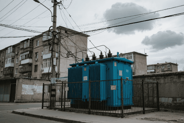
Let’s explore this process in more detail:
Turns Ratio Principle
The turns ratio is the key to voltage transformation:
- Step-Up: Secondary turns > Primary turns
- Step-Down: Secondary turns < Primary turns
- Isolation: Secondary turns = Primary turns
The voltage ratio equals the turns ratio in an ideal transformer:
Vs / Vp = Ns / Np
Where Vs and Vp are secondary and primary voltages, and Ns and Np are secondary and primary turns.
Step-Up Transformers
Step-up transformers increase voltage. They’re used in:
- Power Generation: To increase generator voltage for transmission
- Renewable Energy: To boost voltage from solar or wind farms for grid connection
- Electronics: In devices like inverters or boost converters
I once worked on a step-up transformer for a wind farm. We had to carefully design it to handle the variable input from the wind turbines while providing a stable high-voltage output for the grid.
Step-Down Transformers
Step-down transformers decrease voltage. They’re used in:
- Distribution: To reduce transmission voltage for local distribution
- Industrial Applications: To provide appropriate voltage for machinery
- Consumer Electronics: In power adapters for devices
Step-down transformers are crucial in bringing high transmission voltages down to levels safe for homes and businesses. I’ve designed distribution transformers that step down voltage from 11kV to 415V for commercial buildings.
Autotransformers
Autotransformers are a special type that use a single winding for both primary and secondary:
| Advantages | Disadvantages |
|---|---|
| Smaller size | No electrical isolation |
| Lower cost | Limited voltage ratios |
| Higher efficiency | Safety concerns in some applications |
I’ve used autotransformers in projects where size and cost were critical, and isolation wasn’t necessary. They can be very effective in the right applications.
Tap Changers
Tap changers allow for fine-tuning of the voltage ratio:
- Off-Load Tap Changers: Adjusted when the transformer is de-energized
- On-Load Tap Changers: Can be adjusted while the transformer is in operation
These devices are crucial for maintaining stable output voltage despite fluctuations in input voltage or load. I’ve worked with utilities to implement on-load tap changers in their distribution transformers, significantly improving power quality for their customers.
What Are the Key Components of a Power Transformer and Their Functions?
Understanding the components of a power transformer is crucial for anyone working with these devices. Each part plays a vital role in the transformer’s operation. I’ve spent countless hours designing and optimizing these components.
The key components of a power transformer include the core, windings, insulation system, cooling system, and tap changers. Each component contributes to the transformer’s ability to efficiently and safely transform voltage levels.
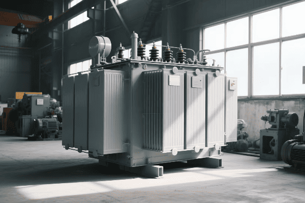
Let’s explore each of these components in detail:
Core
The core is the magnetic heart of the transformer:
- Material: Usually made of silicon steel laminations
- Function: Provides a path for magnetic flux
- Types: Core-type or shell-type designs
I once worked on a project comparing different core designs. We found that the shell-type design provided better magnetic shielding, which was crucial for the sensitive equipment nearby.
Windings
Windings are the electrical part of the transformer:
| Primary Winding | Secondary Winding |
|---|---|
| Connects to power source | Connects to load |
| Creates magnetic field | Experiences induced voltage |
| Determines input current | Determines output voltage |
The design of windings is critical. I remember a project where we redesigned the winding layout to improve cooling. It significantly increased the transformer’s power handling capacity.
Insulation System
The insulation system prevents short circuits and allows for high voltage operation:
- Oil Insulation: Used in large power transformers
- Solid Insulation: Paper or polymer materials
- Gas Insulation: SF6 gas in some special applications
Proper insulation is crucial for safety and longevity. I’ve seen transformers fail due to insulation breakdown, which can be catastrophic.
Cooling System
The cooling system prevents overheating:
- Oil-Immersed Cooling: ONAN, ONAF, OFAF types
- Dry-Type Cooling: Air Natural (AN) or Air Forced (AF)
Choosing the right cooling system depends on the transformer’s size, location, and load profile. I once designed a custom cooling system for a transformer located in an extremely hot climate. It involved a combination of oil circulation and external radiators.
Tap Changers
Tap changers allow for voltage adjustment:
- Off-Load Tap Changers: Adjusted when transformer is de-energized
- On-Load Tap Changers: Can be adjusted during operation
Tap changers are crucial for maintaining stable output voltage. I’ve worked on projects implementing smart tap changers that automatically adjust based on load conditions, significantly improving power quality.
Bushings
Bushings are the connection points between the transformer’s internal wiring and the external electrical system:
- Function: Provide insulated passage for conductors
- Types: Oil-filled, solid, or gas-filled
Proper bushing design is crucial for preventing flashovers. I once investigated a transformer failure that was traced back to a poorly designed bushing. It taught me the importance of every component, no matter how small it might seem.
Tank and Conservator
For oil-filled transformers:
- Tank: Houses the core, windings, and oil
- Conservator: Allows for oil expansion and contraction
These components are crucial for containing the oil and maintaining proper insulation. I’ve been involved in designing transformer tanks that can withstand extreme environmental conditions, from arctic cold to desert heat.
Conclusion
Power transformers are complex devices that rely on electromagnetic induction to transfer and transform electrical energy. Understanding their components and principles is crucial for anyone working in the power industry or studying electrical engineering.
Power outages can be frustrating. I’ve experienced them firsthand, and they always make me wonder about our electrical systems.
Three-phase power transformers are key components in electrical grids. They convert high-voltage electricity from power plants to lower voltages for homes and businesses. These transformers ensure efficient and reliable power distribution across long distances.

Let’s dive deeper into the world of three-phase power transformers. I’ll share my insights from years of working in the power industry.
What Are the Fundamental Principles Behind Three Phase Power Transformer Operation?
Have you ever wondered how electricity travels from power plants to your home? It’s a fascinating process that I’ve studied for years.
Three-phase power transformers work on the principle of electromagnetic induction. They use three sets of primary and secondary windings to transfer electrical energy between two circuits with different voltage levels.
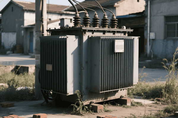
Let me break down the fundamental principles of three-phase power transformer operation:
Electromagnetic Induction
Electromagnetic induction is the heart of transformer operation. I remember learning about this in my early days as an electrical engineer. It’s amazing how a simple principle can have such a huge impact on our daily lives.
- Primary Windings: These are connected to the power source.
- Secondary Windings: These deliver power to the load.
- Magnetic Core: This links the primary and secondary windings.
When alternating current flows through the primary windings, it creates a changing magnetic field. This field induces a voltage in the secondary windings. The ratio of primary to secondary turns determines the voltage transformation.
Three-Phase System
A three-phase system uses three alternating currents, each offset by 120 degrees. This system is more efficient than single-phase for power transmission. Here’s why:
| Advantage | Explanation |
|---|---|
| Constant Power Delivery | Three phases provide a steady power flow |
| Higher Power Capacity | Can transmit more power with less material |
| Balanced Load | Reduces vibration in generators and motors |
Voltage Transformation
The voltage transformation in a three-phase transformer follows this principle:
Vs / Vp = Ns / Np
Where:
- Vs = Secondary voltage
- Vp = Primary voltage
- Ns = Number of secondary turns
- Np = Number of primary turns
This relationship allows us to step up or step down voltage as needed. It’s crucial for efficient power transmission over long distances.
How Do Three Phase Power Transformers Differ from Single Phase Transformers in Design and Function?
I often get asked about the differences between three-phase and single-phase transformers. It’s a great question that highlights the complexity of power systems.
Three-phase transformers have three sets of windings and can handle higher power loads. Single-phase transformers have one set of windings and are used for lower power applications. Three-phase systems are more efficient for power transmission and distribution.
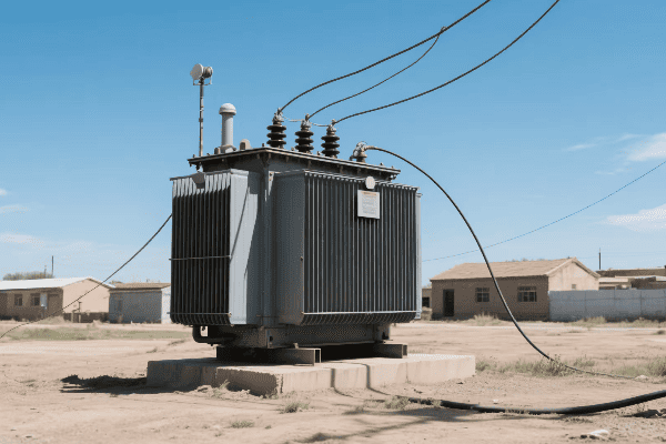
Let’s explore the key differences:
Core Design
The core design is one of the most visible differences between three-phase and single-phase transformers.
-
Three-Phase Core:
- Usually has a three-limb or five-limb design
- More efficient use of core material
- Better magnetic flux distribution
-
Single-Phase Core:
- Typically has a simpler two-limb design
- Less efficient in material usage
- Simpler construction
I remember working on a project where we had to choose between a bank of single-phase transformers and a three-phase unit. The three-phase option saved us significant space and material costs.
Winding Configuration
The winding configuration is another crucial difference:
| Three-Phase Transformer | Single-Phase Transformer |
|---|---|
| Three sets of primary and secondary windings | One set of primary and secondary windings |
| Can be connected in delta or star configuration | Simpler connection options |
| Allows for flexible voltage and current ratios | Limited voltage and current ratio options |
Power Handling Capacity
Three-phase transformers generally have higher power handling capacities:
-
Three-Phase:
- Can handle higher power loads
- More suitable for industrial and utility-scale applications
- More efficient for long-distance power transmission
-
Single-Phase:
- Lower power handling capacity
- Commonly used in residential and small commercial settings
- Less efficient for high-power applications
Efficiency and Size
In my experience, three-phase transformers often come out on top in terms of efficiency and size:
-
Efficiency:
- Three-phase transformers are generally more efficient
- They have lower core losses per unit of power transferred
- Better utilization of core material
-
Size:
- For the same power rating, a three-phase transformer is usually smaller
- This leads to lower material costs and space requirements
- Important for substation design and urban installations
What Are the Key Components and Their Roles in a Three Phase Power Transformer?
Understanding the components of a three-phase transformer is crucial. I’ve spent countless hours working with these machines, and each part plays a vital role.
The key components of a three-phase power transformer include the core, windings, insulation, cooling system, and tap changers. Each component contributes to the transformer’s ability to efficiently and safely transform voltage levels in a three-phase power system.
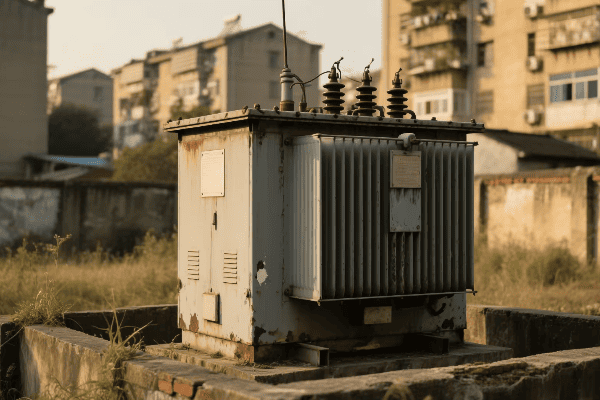
Let’s break down these components and their roles:
Core
The core is the heart of the transformer. It’s typically made of high-grade silicon steel laminations.
-
Function:
- Provides a low reluctance path for magnetic flux
- Minimizes eddy current losses
-
Types:
- Three-limb core: Most common for three-phase transformers
- Five-limb core: Used for larger units or special applications
I once worked on a project where we had to choose between a three-limb and a five-limb core. The five-limb design was more expensive but offered better performance under unbalanced load conditions.
Windings
Windings are crucial for voltage transformation. They’re usually made of copper or aluminum.
| Primary Windings | Secondary Windings |
|---|---|
| Connected to the power source | Connected to the load |
| Typically have more turns for step-down transformers | Fewer turns for step-down transformers |
| Made of insulated wire | Also made of insulated wire |
The winding design affects the transformer’s efficiency and short-circuit strength. I’ve seen how different winding configurations can significantly impact a transformer’s performance.
Insulation
Insulation is critical for safety and proper operation. It prevents short circuits and allows for higher voltage operation.
-
Types of Insulation:
- Oil immersion: Common for large power transformers
- Dry type: Used in indoor installations
-
Insulation Components:
- Paper insulation on windings
- Oil in oil-immersed transformers
- Air or epoxy resin in dry-type transformers
Proper insulation maintenance is crucial. I’ve seen transformers fail due to insulation breakdown, which can be catastrophic.
Cooling System
The cooling system prevents overheating, which can damage the transformer.
-
Oil-Immersed Transformers:
- ONAN (Oil Natural Air Natural)
- ONAF (Oil Natural Air Forced)
- OFAF (Oil Forced Air Forced)
-
Dry-Type Transformers:
- AN (Air Natural)
- AF (Air Forced)
Choosing the right cooling system depends on the transformer’s size, location, and load profile. I’ve worked on projects where the cooling system design was crucial for ensuring reliable operation in harsh environments.
Tap Changers
Tap changers allow for voltage adjustment to maintain proper output voltage.
-
Types:
- On-Load Tap Changers (OLTC): Can change taps while the transformer is energized
- Off-Load Tap Changers: Require the transformer to be de-energized for tap changes
-
Function:
- Compensate for voltage variations in the power system
- Maintain stable output voltage
Tap changers are complex mechanisms that require regular maintenance. I’ve seen how proper tap changer operation can significantly improve power quality and transformer lifespan.
Where Are Three Phase Power Transformers Commonly Used in Industrial and Utility Applications?
Throughout my career, I’ve seen three-phase power transformers used in various settings. Their versatility never ceases to amaze me.
Three-phase power transformers are widely used in power generation plants, transmission substations, distribution networks, and large industrial facilities. They’re essential for voltage transformation in the power grid and for powering heavy machinery in factories.
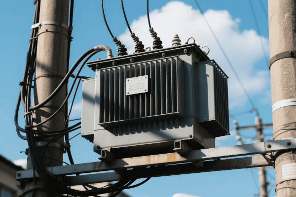
Let’s explore the common applications of three-phase power transformers:
Power Generation Plants
In power plants, three-phase transformers play a crucial role:
-
Step-Up Transformers:
- Increase generator voltage for long-distance transmission
- Typically raise voltage from 15-25 kV to 115-765 kV
-
Auxiliary Transformers:
- Supply power to plant equipment
- Step down high voltage to usable levels for motors and controls
I once worked on a project to upgrade a power plant’s main step-up transformer. The new unit’s improved efficiency resulted in significant energy savings for the plant.
Transmission Substations
Transmission substations use large three-phase transformers to manage power flow:
| Function | Voltage Levels |
|---|---|
| Step-Up | Increase voltage for long-distance transmission |
| Step-Down | Reduce voltage for regional distribution |
| Interconnection | Match voltages between different transmission lines |
These transformers are often massive. I remember being in awe the first time I saw a 500 MVA transformer being installed at a substation.
Distribution Networks
In distribution networks, three-phase transformers are used to:
- Step down voltage from sub-transmission levels to distribution levels
- Supply power to commercial and industrial customers
- Feed single-phase transformers for residential areas
The design of distribution transformers often involves balancing cost, efficiency, and reliability. I’ve worked on projects where we had to carefully consider load growth projections to size these transformers correctly.
Industrial Facilities
Large industrial facilities rely heavily on three-phase power:
-
Main Incoming Transformers:
- Step down utility voltage to plant distribution voltage
- Often include features like on-load tap changers for voltage regulation
-
Process Power Transformers:
- Supply power to specific production lines or equipment
- May have special designs for harsh environments or variable loads
-
Arc Furnace Transformers:
- Specialized units for steel production
- Handle extreme load variations and high currents
I once consulted on a project for a large aluminum smelter. The transformers there were some of the most robust I’ve ever seen, designed to handle the enormous power demands of the electrolysis process.
Renewable Energy Integration
With the growth of renewable energy, three-phase transformers are increasingly used in:
-
Wind Farms:
- Step up voltage from individual turbines
- Combine power for transmission to the grid
-
Solar Power Plants:
- Convert DC output from inverters to AC
- Step up voltage for grid connection
-
Energy Storage Systems:
- Interface large battery systems with the grid
- Manage bidirectional power flow
The integration of renewables has brought new challenges in transformer design. I’ve been involved in projects where we had to design transformers to handle the variable output of wind and solar farms.
How Do Three Phase Power Transformers Contribute to Efficient Power Distribution and Transmission?
Efficiency in power systems has always been a passion of mine. Three-phase transformers play a crucial role in this area.
Three-phase power transformers enhance efficiency in power distribution and transmission by reducing losses, enabling high-voltage transmission, and providing a balanced power supply. They allow for more economical power transfer over long distances and better utilization of electrical infrastructure.

Let’s delve into how three-phase transformers contribute to efficiency:
Reduced Transmission Losses
Three-phase systems, enabled by three-phase transformers, significantly reduce transmission losses:
-
Lower Current for Same Power:
- Three-phase systems carry more power at lower currents
- Lower currents mean lower I²R losses in transmission lines
-
Balanced Load Distribution:
- Even distribution of load across three phases
- Reduces overall system stress and losses
I once worked on a project to upgrade a long-distance transmission line. By switching from single-phase to three-phase, we reduced line losses by almost 30%.
High Voltage Transmission
Three-phase transformers enable high voltage transmission, which is key to efficiency:
| Voltage Level | Advantage |
|---|---|
| Higher Voltage | Lower current for same power |
| Lower Current | Reduced line losses |
| Increased Capacity | More power transmitted on existing lines |
High voltage transmission is crucial for long-distance power transfer. I’ve seen how upgrading to higher voltage levels can dramatically improve system efficiency and capacity.
Power Quality Improvement
Three-phase transformers contribute to better power quality:
-
Voltage Regulation:
- On-load tap changers maintain stable voltage
- Improved voltage profile across the network
-
Harmonic Mitigation:
- Special designs can help reduce harmonic distortion
- Improves overall system efficiency and equipment lifespan
-
Phase Balancing:
- Helps maintain balanced voltages across the three phases
- Reduces losses and improves equipment performance
I’ve worked on projects where installing advanced three-phase transformers with on-load tap changers significantly improved voltage stability in a large industrial park.
Efficient Substation Design
Three-phase transformers allow for more efficient substation designs:
-
Compact Footprint:
- Single three-phase unit vs. three single-phase units
- Reduces land requirements and construction costs
-
Simplified Connections:
- Fewer connections mean lower installation and maintenance costs
- Reduced potential points of failure
-
Integrated Cooling Systems:
- More efficient cooling for three-phase units
- Better overall system reliability
In my experience, using three-phase transformers in substations often leads to significant space savings and simpler maintenance procedures.
Renewable Energy Integration
Three-phase transformers are crucial for efficiently integrating renewable energy sources:
-
Wind Farms:
- Step-up transformers at each turbine
- Larger substation transformers for grid connection
-
Solar Plants:
- Inverter transformers for DC to AC conversion
- Step-up transformers for grid connection
-
Energy Storage:
- Bidirectional power flow management
- Grid stabilization during peak demand
I’ve been involved in several renewable energy projects where the choice of transformer was critical for maximizing energy capture and minimizing losses.
Conclusion
Three-phase power transformers are vital for efficient power distribution. They enable high-voltage transmission, reduce losses, and support renewable energy integration. Understanding their principles and applications is crucial for modern power systems.
Many project managers feel overwhelmed when choosing dry type transformer types: the wide range of models, environmental differences, and the balance between efficiency and cost can make the decision difficult. The wrong choice may lead to high energy consumption or even safety risks. This article breaks down the different types, compares performance, price, and lifespan, and provides a buyer-oriented guide to help you quickly identify the most suitable dry type transformer for your project.
Choosing the best dry type transformer involves understanding various types, considering environmental factors, evaluating electrical specifications, assessing safety features, and balancing efficiency with cost. This comprehensive approach ensures optimal performance, safety, and long-term value for your specific project needs.
As someone who has spent years working with dry type transformers, I’ve seen firsthand how crucial it is to make the right choice. The wrong selection can lead to inefficiency, safety hazards, or even complete system failure. Let’s dive into the key factors you need to consider to make the best choice for your project.
What Are the Different Dry Type Transformer Types and Applications?
Have you ever felt overwhelmed by the sheer number of dry type transformer options? You’re not alone. Many of my clients initially find the variety confusing. But understanding these options is crucial for making the right choice.
Dry type transformers come in several varieties, including cast resin, vacuum pressure impregnated (VPI), and open wound types. Each has unique characteristics suited for different applications, from indoor installations to harsh environments, and from low to medium voltage requirements.
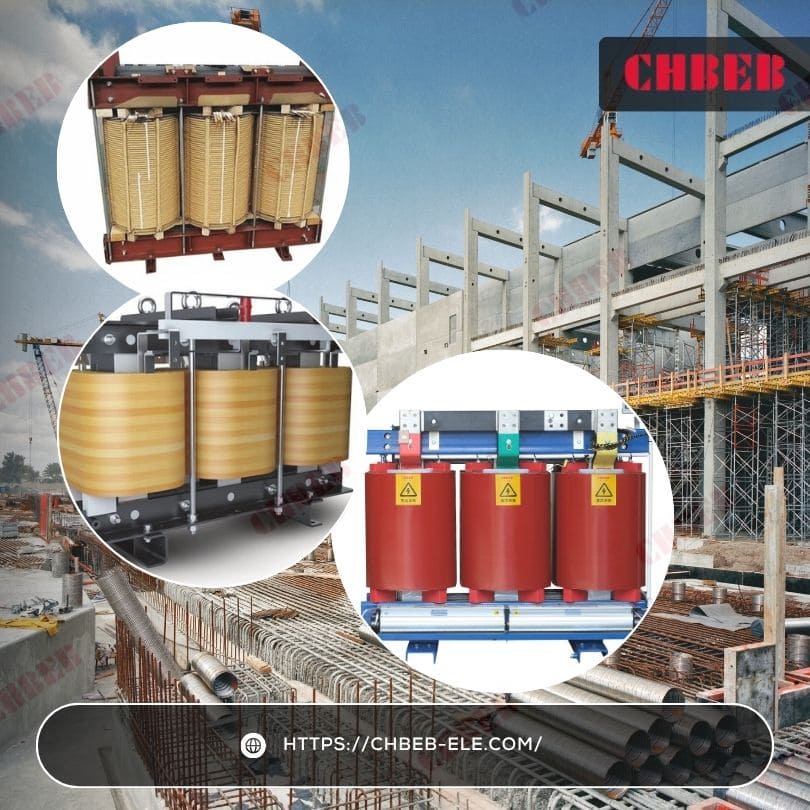
Types of Dry Transformers
I remember a project where a client initially chose the wrong type of dry transformer, leading to overheating issues. Let’s break down these varieties to help you avoid such mistakes.
Cast Resin Transformers: Why Choose for Harsh Environments?
Cast resin transformers are known for their durability:
- Construction: Windings are encased in epoxy resin.
- Applications: Ideal for harsh environments and indoor use.
- Advantages: Excellent fire resistance and low maintenance.
I once recommended a cast resin transformer for a chemical plant. Its resistance to harsh chemicals and fire safety features made it the perfect choice for that environment.
VPI Transformers: Balancing Performance and Cost
VPI transformers offer a good middle ground:
- Process: Windings are vacuum impregnated with varnish or resin.
- Applications: Suitable for most indoor and some outdoor applications.
- Benefits: Good balance of cost and performance.
For a recent office building project, we chose VPI transformers. They provided the necessary performance at a more budget-friendly price point compared to cast resin options.
Open Wound Transformers: When Simplicity Is Enough
Open wound transformers are the simplest type:
- Design: Windings are exposed, with minimal enclosure.
- Use Cases: Best for clean, dry environments with low risk of contamination.
- Advantages: Lower cost and easier cooling.
| Type | Environmental Resistance | Cost | Best For |
|---|---|---|---|
| Cast Resin | High | High | Harsh environments, critical applications |
| VPI | Medium | Medium | General purpose, indoor/outdoor |
| Open Wound | 1. Mechanical Strength: Windings designed to withstand electromagnetic forces. |
- Bracing Systems: Additional support structures for windings.
- Testing: Rigorous short-circuit testing to ensure durability.
I once worked on upgrading transformers in a facility with frequent voltage fluctuations. We chose units with enhanced short-circuit strength, which proved crucial during several grid disturbances.
How Do Cooling Systems Improve Transformer Performance?
Efficient cooling is essential for safety and longevity:
- Natural Air Cooling: Suitable for smaller transformers in clean environments.
- Forced Air Cooling: Uses fans to enhance air circulation for better cooling.
- Advanced Cooling Designs: Some transformers use heat pipes or other innovative cooling methods.
During a recent data center project, we implemented a hybrid cooling system combining forced air with heat pipe technology. This allowed the transformers to handle higher loads without overheating, crucial for the center’s demanding environment.
Why Does Ease of Inspection Save Time and Cost?
Regular inspections are key to maintaining safety:
- Visible Windings: Some designs allow for easy visual inspection of windings.
- Accessible Connections: Ensure terminals and tap changers can be easily checked.
- Monitoring Ports: Look for designs that allow for easy connection of diagnostic equipment.
I recently advised a client to choose a transformer design with easily accessible inspection points. This feature has made their maintenance routines more efficient and effective, catching potential issues early.
What Safety Standards Must a Dry Type Transformer Meet?
Adherence to safety standards is non-negotiable:
- UL Listing: Ensures compliance with Underwriters Laboratories safety standards.
- IEEE/ANSI Standards1: Provide guidelines for design, testing, and performance.
- IEC Standards: International standards for electrical equipment.
In every project I work on, I insist on transformers that meet or exceed relevant safety standards. It’s not just about compliance; it’s about ensuring the highest level of safety for personnel and equipment.
How Do Maintenance Requirements Differ Among Transformer Types?
Different transformer types have varying maintenance needs:
- Cast Resin Transformers: Generally require minimal maintenance.
- VPI Transformers: May need periodic inspections and cleaning.
- Open Wound Transformers: Require more frequent maintenance and environmental protection.
| Transformer Type | Maintenance Frequency | Typical Maintenance Tasks |
|---|---|---|
| Cast Resin | Annually | Visual inspection, connection checks |
| VPI | Semi-annually | Cleaning, insulation tests |
| Open Wound | Quarterly | Thorough cleaning, detailed inspections |
For a client with limited maintenance resources, we opted for cast resin transformers. Their low maintenance requirements aligned perfectly with the client’s capabilities while ensuring reliable operation.
How Can Environmental Protection Extend Transformer Lifespan?
Consider the installation environment:
- Enclosure Ratings: Choose appropriate IP ratings for the environment.
- Corrosion Resistance: Important in coastal or industrial areas.
- UV Protection: Necessary for outdoor installations.
In a coastal installation project, we selected transformers with enhanced corrosion protection and UV-resistant enclosures. These features have significantly extended the transformers’ lifespan in the harsh seaside environment.
What Noise Control Solutions Keep Transformers Quiet?
Transformer noise can be a significant issue in some settings:
- Noise Levels: Consider the acoustic environment of the installation site.
- Sound Enclosures: May be necessary in noise-sensitive areas.
- Low-Noise Designs: Some transformers are specifically designed for quieter operation.
For a transformer installation near residential areas, we chose low-noise models and implemented additional sound barriers. This approach ensured compliance with local noise ordinances and maintained good relations with nearby residents.
Evaluating safety features and maintenance requirements is crucial when selecting a dry type transformer. It’s not just about meeting basic electrical specifications; it’s about ensuring long-term safety, reliability, and ease of maintenance. By carefully considering these factors, you can select a transformer that not only meets your power needs but also aligns with your safety standards and maintenance capabilities.
Remember, a transformer that’s safe and easy to maintain is more likely to provide reliable service throughout its lifespan. In my years of experience, I’ve found that investing in better safety features and considering maintenance needs upfront often leads to lower total costs and fewer headaches down the line. Choose wisely, and your transformer will be a reliable asset for years to come.
What Role Do Efficiency and Cost Considerations Play in Selecting the Optimal Dry Type Transformer?
Have you ever been tempted to buy the cheapest option, only to regret it later? When it comes to dry type transformers, the lowest price tag doesn’t always mean the best value. But how do you strike the right balance between efficiency and cost?
Efficiency and cost considerations play a crucial role in selecting the optimal dry type transformer. While high-efficiency transformers may have higher upfront costs, they often provide better long-term value through energy savings. The total cost of ownership, including initial price, operational costs, and expected lifespan, should guide the selection process.
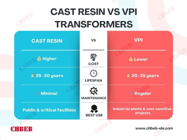
Efficiency vs Cost
I once had a client who chose the cheapest transformer option available. Within three years, they spent more on energy losses than they would have on a higher-efficiency unit. Let’s explore how to avoid such costly mistakes.
How to Calculate Initial Cost vs. Total Cost of Ownership (TCO)?
Looking beyond the price tag is crucial:
- Purchase Price: The upfront cost of the transformer.
- Energy Costs: Calculated based on efficiency and expected load.
- Maintenance Costs: Regular upkeep and potential repairs.
- Expected Lifespan: Longer-lasting transformers can offset higher initial costs.
In a recent industrial project, we compared two transformers:
| Aspect | Standard Model | High-Efficiency Model |
|---|---|---|
| Initial Cost | $50,000 | $65,000 |
| Annual Energy Cost | $10,000 | $7,000 |
| Annual Maintenance | $2,000 | $1,500 |
| Expected Lifespan | 20 years | 25 years |
Despite the higher upfront cost, the high-efficiency model was projected to save over $100,000 over its lifetime.
What Efficiency Standards Should You Pay Attention To?
Understanding efficiency ratings is key:
- DOE Efficiency Standards: Specify minimum efficiency levels for distribution transformers.
- NEMA Premium Efficiency: Exceeds DOE standards for even greater energy savings.
- European Eco-design Requirements: Stringent efficiency standards for the EU market.
I recently helped a client upgrade their old transformers to models meeting NEMA Premium efficiency2 standards. The energy savings paid for the new transformers in just over four years, with substantial savings continuing thereafter.
Why Does Load Factor Greatly Affect Transformer Efficiency?
Efficiency varies with load:
- Peak Efficiency Point: Typically occurs at 40-50% of rated load.
- Load Profile Analysis: Understanding your typical load helps choose the right transformer.
- No-Load Losses: Important for transformers that are energized but lightly loaded for long periods.
For a university campus project, we analyzed the load profile across different seasons and times of day. This led us to select transformers with peak efficiency points that matched the campus’s average load, resulting in significant energy savings.
How Do Environmental Regulations Impact Future Costs?
Environmental considerations can affect long-term costs:
- Energy Efficiency Regulations: Stricter standards may require future upgrades.
- Carbon Footprint: More efficient transformers can reduce overall emissions.
- End-of-Life Disposal: Consider the costs and environmental impact of disposal.
In a recent project for an environmentally conscious client, we chose ultra-high efficiency transformers. While more expensive initially, they aligned with the company’s sustainability goals and helped them meet stringent environmental regulations.
What Installation and Space Considerations Should You Plan For?
Don’t forget about installation:
- Size and Weight: More efficient transformers may be larger and heavier.
- Installation Requirements: Consider any special mounting or cooling needs.
- Space Constraints: In some cases, a more compact, less efficient unit might be necessary.
For a retrofit project in a cramped urban substation, we had to balance efficiency with size constraints. We opted for a slightly less efficient but more compact model that fit the available space without requiring costly building modifications.
Why Does Reliability and Downtime Cost Matter?
Consider the cost of potential failures:
- Build Quality: Higher-quality transformers may have better reliability.
- Downtime Costs: Assess the financial impact of potential outages.
- Warranty and Support: Factor in the value of better warranty terms and manufacturer support.
I once advised a manufacturing client to invest in a premium transformer with an extended warranty. This decision paid off when a minor issue was quickly resolved under warranty, avoiding costly downtime.
How to Future-Proof Your Transformer Investment?
Think about future needs:
- Load Growth: Consider transformers that can handle potential increases in power demand.
- Technology Advancements: Some designs may be more adaptable to future smart grid technologies.
- Regulatory Changes: Anticipate potential changes in efficiency standards.
For a growing tech company, we selected a modular transformer system with high efficiency ratings. This choice allowed for easy expansion as the company grew and ensured compliance with expected future efficiency standards.
Balancing efficiency and cost in dry type transformer selection is not just about finding the cheapest option; it’s about finding the best value for your specific needs. While high-efficiency transformers may have higher upfront costs, they often provide better long-term value through energy savings, reduced maintenance, and longer service life.
When making your decision, consider the following steps:
- Calculate the Total Cost of Ownership over the expected life of the transformer.
- Analyze your load profile to choose a transformer with the right efficiency characteristics.
- Consider future growth and potential regulatory changes.
- Factor in installation costs and space constraints.
- Evaluate the potential costs of downtime and the value of reliability.
Remember, the right choice balances immediate budget constraints with long-term operational benefits. By carefully weighing these factors, you can select a transformer that not only fits your current budget but also provides optimal performance and value throughout its entire lifespan.
From Selection Challenges to Reliable Solutions — How CHBEB Helps You Choose the Right Dry Type Transformer

Many project managers and engineers face the same challenges when selecting a dry type transformer: balancing safety, efficiency, and cost while navigating complex installation environments. Recent industry studies show that the true pain points often lie beyond the initial purchase — in Total Cost of Ownership (TCO), environmental adaptation, and long-term reliability management.
At CHBEB, we understand these challenges not just from theory, but from decades of manufacturing and project experience. With over 60 years of transformer production expertise and three advanced factories in Wenzhou and Nanjing, our engineering team works closely with clients worldwide to design solutions that directly address the technical, environmental, and financial pain points identified in the dry type transformer market.
How CHBEB Solves Real-World Pain Points
- 1. Technical Clarity — Simplifying VPI vs. Cast Resin Choices
Choosing between VPI and Cast Resin transformers shouldn’t be a gamble. CHBEB provides detailed thermal, load, and environmental simulations, helping you visualize the performance trade-offs before purchase. Our engineers can also customize winding protection, cooling design, and resin formulation to match your exact operating conditions. - 2. Environmental Reliability — Built for Harsh or Confined Spaces
Our dry type transformers are tested under high humidity, dust, and temperature stress conditions to ensure consistent performance. For coastal or industrial installations, we offer enhanced anti-corrosion coatings, sealed enclosures (IP54/IP65), and forced-air or hybrid cooling systems that maintain stability even in limited ventilation environments. - 3. TCO Optimization — Lower Lifetime Cost, Not Just Lower Price
Instead of focusing solely on initial CAPEX, CHBEB helps clients model long-term energy savings, load efficiency, and maintenance intervals. Our high-efficiency core materials and optimized coil designs reduce energy loss by up to 20%, cutting total operational costs while meeting or exceeding IEC, DOE, and NEMA Premium Efficiency standards. - 4. Service & Diagnostics — Making Maintenance Simple and Predictable
Each CHBEB transformer integrates accessible inspection points, embedded temperature sensors, and optional digital monitoring interfaces that allow predictive maintenance and early fault detection. This minimizes downtime and aligns with the industry’s shift toward condition-based maintenance instead of fixed-cycle servicing.
Why CHBEB Is the Partner for Your Next Project
- Certified by ISO 9001 / ISO 14001 / ISO 45001 and compliant with IEC & GB standards.
- End-to-end testing, including routine, type, and special tests before shipment.
- Flexible customization for voltage levels, cooling systems, enclosure ratings, and winding materials.
- Global supply experience in renewable energy, utilities, EPC projects, and industrial facilities.
Plan with Confidence
Whether you’re managing a data center, utility substation, or industrial plant, CHBEB engineers can help you evaluate the optimal dry type transformer configuration for your budget, efficiency goals, and environmental conditions. Start your project with confidence — we don’t just sell transformers; we deliver total reliability solutions.
Contact CHBEB for a Technical Consultation
Conclusion: How to Select the Best Dry Type Transformer for Your Project?
Selecting the best dry type transformer involves carefully considering various types, environmental factors, electrical specifications, safety features, maintenance requirements, efficiency, and cost. By evaluating these aspects comprehensively, you can choose a transformer that offers optimal performance, safety, and long-term value for your specific project needs.
