Have you ever wondered how electricity reaches every corner of a bustling city? The answer lies in those unassuming boxes you see on streets and in buildings. These electrical transformer boxes are the unsung heroes of urban power distribution.
Electrical transformer boxes play a crucial role in urban power distribution by stepping down high voltage electricity to usable levels for homes and businesses. They act as key distribution points, manage voltage for various needs, ensure space efficiency, integrate with smart city technologies, and adapt to growing urban energy demands.
In this article, I’ll explain how these transformer boxes support the complex power needs of our cities. We’ll explore their role in the urban power grid, voltage management, space efficiency, smart city integration, and how they meet growing energy demands. Whether you’re a curious resident or a budding engineer, this guide will help you understand the backbone of urban power distribution.
The Urban Power Grid: Transformer Boxes as Key Distribution Points?
Have you ever looked at a city skyline and wondered how electricity flows through this concrete jungle? The urban power grid is a complex network, but at its heart are the humble transformer boxes. But what exactly is their role in this intricate system?
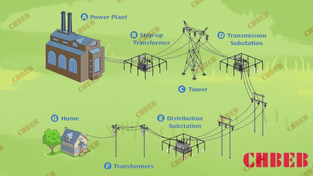
Transformer boxes serve as crucial distribution points in the urban power grid. They receive high-voltage electricity from substations and step it down to lower, safer voltages for local use. These boxes act as nodes in a vast network, ensuring power reaches every building and street in the city efficiently.
Diving Deeper into the Role of Transformer Boxes
Let’s break down the key functions of transformer boxes in the urban power grid:
1. Power Distribution Nodes
Transformer boxes act as vital nodes in the urban power distribution network:
- They receive high-voltage power from substations
- They distribute lower-voltage power to local areas
- They create a bridge between the main grid and end-users
I once worked on a project to upgrade the power grid in a rapidly growing urban area. We strategically placed transformer boxes to create an efficient distribution network. This approach significantly improved power reliability and reduced transmission losses.
2. Voltage Step-Down
The primary function of these boxes is to step down voltage:
- They typically reduce voltage from thousands to hundreds of volts
- This makes electricity safe for use in homes and businesses
- It allows for more efficient power transmission over long distances
3. Load Management
Transformer boxes play a crucial role in managing power loads:
- They help balance the load across different areas of the city
- They can be adjusted to handle varying power demands
- They prevent overloading of local power lines
Here’s a table showing typical voltage levels in urban power distribution:
| Stage | Voltage Level | Location |
|---|---|---|
| Transmission Lines | 69,000 – 765,000 V | City outskirts |
| Subtransmission | 26,000 – 69,000 V | City substations |
| Primary Distribution | 4,000 – 13,000 V | Street level |
| Secondary Distribution | 120/240 V | Buildings |
In my experience, one of the most challenging aspects of urban power distribution is adapting to the ever-changing landscape of cities. I recall a project in a rapidly developing downtown area where we had to constantly adjust our transformer box placements to accommodate new high-rise buildings. This dynamic environment taught me the importance of flexible and scalable distribution systems.
Another crucial aspect of transformer boxes in urban grids is their role in power quality management. In densely populated areas with a high concentration of electronic devices, power quality issues like harmonics can be significant. We often install specialized transformer boxes with harmonic mitigation features to address these challenges.
Redundancy is another key consideration in urban power grids. I always advocate for a network design that includes multiple transformer boxes serving overlapping areas. This approach ensures that if one box fails, others can pick up the load, minimizing the impact of outages on city residents and businesses.
The placement of transformer boxes in urban environments requires careful planning. In one project, we had to balance technical requirements with aesthetic concerns in a historic district. We ended up designing custom enclosures that blended with the local architecture while still meeting all technical specifications.
Maintenance of transformer boxes in urban settings presents unique challenges. I’ve implemented remote monitoring systems that allow us to track the performance of transformer boxes across the city in real-time. This proactive approach has significantly reduced downtime and improved overall grid reliability.
Lastly, the integration of renewable energy sources into the urban grid is changing the role of transformer boxes. In recent projects, we’ve had to design bi-directional transformer boxes that can handle power flow from rooftop solar panels and other distributed generation sources. This shift towards a more dynamic, two-way power flow is reshaping our approach to urban power distribution.
Understanding the role of transformer boxes in the urban power grid is crucial for anyone involved in city planning, electrical engineering, or even for curious residents. These unassuming boxes are the linchpins of our urban power infrastructure, ensuring that the lights stay on in our bustling cities.
Voltage Management in Cities: How Transformer Boxes Adapt Power for Various Needs?
Have you ever wondered why the massive power lines entering a city don’t fry every electronic device in your home? The secret lies in the sophisticated voltage management performed by transformer boxes. But how exactly do these boxes adapt power for the diverse needs of a city?
Transformer boxes in cities manage voltage by stepping down high transmission voltages to lower, usable levels. They adapt power for various needs by using different transformation ratios, employing tap changers for fine adjustments, and utilizing specialized designs for specific applications like industrial or residential areas.
Exploring Voltage Management Techniques
Let’s delve into how transformer boxes manage and adapt voltage in urban settings:
1. Voltage Step-Down Process
The primary function of transformer boxes is voltage reduction:
- They use electromagnetic induction to step down voltage
- Different winding ratios achieve various voltage levels
- This process makes high-voltage power safe for local distribution
I once worked on a project where we had to design a transformer box to step down 69,000 volts to 480 volts for a large industrial complex. The precision required in the winding ratios was crucial for ensuring stable power supply to sensitive manufacturing equipment.
2. Tap Changers for Fine Adjustments
Many urban transformer boxes include tap changers:
- These allow for small voltage adjustments without interrupting power
- They help maintain consistent voltage despite fluctuations in demand
- Some modern systems use automatic tap changers for real-time adjustments
3. Specialized Designs for Different Needs
Transformer boxes are often customized for specific urban applications:
- Residential areas typically use transformers with 120/240V output
- Commercial districts might require 208Y/120V or 480Y/277V systems
- Industrial zones often need higher voltages and more robust designs
Here’s a table showing common voltage adaptations in urban settings:
| Application | Input Voltage | Output Voltage | Typical Transformer Type |
|---|---|---|---|
| Residential | 7,200V | 120/240V | Single-phase pad-mounted |
| Small Commercial | 12,470V | 208Y/120V | Three-phase pad-mounted |
| Large Commercial | 34,500V | 480Y/277V | Three-phase vault-type |
| Industrial | 69,000V | 4,160V | Substation-class |
In my experience, one of the most challenging aspects of voltage management in cities is dealing with the diverse and changing needs of urban development. I recall a project in a rapidly gentrifying neighborhood where we had to upgrade the transformer boxes to handle the increased power demands of new high-end appliances and electric vehicle charging stations. This required a careful balance of load forecasting and flexible transformer designs.
Power quality is another critical consideration in urban voltage management. In areas with a high concentration of electronic loads, like office districts or tech hubs, we often implement transformer boxes with advanced harmonic mitigation features. I once worked on a project for a data center where we used specially designed K-factor transformers to handle the non-linear loads without overheating.
The integration of renewable energy sources adds another layer of complexity to voltage management. In a recent project involving a large-scale solar installation in an urban area, we had to design transformer boxes that could handle bidirectional power flow and voltage fluctuations associated with intermittent solar generation. This required sophisticated voltage regulation systems and smart grid integration.
Energy efficiency is increasingly important in urban transformer design. I’ve been involved in projects where we’ve replaced older transformer boxes with high-efficiency models. The energy savings over time can be substantial, often justifying the higher initial cost. In one case, we calculated a 30% reduction in transformer losses after upgrading to more efficient units.
Noise reduction is another factor we consider in urban voltage management. In densely populated areas, the hum from transformer boxes can be a nuisance. I’ve worked on developing low-noise transformer designs that use advanced core materials and innovative cooling systems to minimize audible noise while maintaining efficient voltage management.
Lastly, the trend towards underground utilities in many cities is changing how we approach transformer box design. In a recent downtown revitalization project, we installed a network of underground vault-type transformers. This not only improved the aesthetics of the area but also provided better protection for the equipment from weather and physical damage.
Understanding the intricacies of voltage management in urban transformer boxes is crucial for ensuring reliable, efficient, and safe power distribution in our cities. As urban energy needs continue to evolve, so too will the technologies and strategies we use to manage and adapt voltage in our transformer boxes.
Space Efficiency and Safety: Advantages of Transformer Boxes in Dense Urban Areas?
Have you ever wondered how cities manage to fit all the necessary electrical infrastructure into such crowded spaces? The answer lies in the clever design of transformer boxes. But what makes these boxes so advantageous in dense urban environments?
Transformer boxes offer significant space efficiency and safety advantages in dense urban areas. Their compact design allows for installation in tight spaces, while their enclosed nature enhances safety. These boxes can be pad-mounted, vault-type, or even integrated into buildings, maximizing land use and minimizing public exposure to high-voltage equipment.
Exploring Space Efficiency and Safety Features
Let’s delve into the key advantages of transformer boxes in urban settings:
1. Compact Design
Transformer boxes are engineered for space efficiency:
- They can be installed in small areas, often on sidewalks or in basements
- Vertical designs maximize use of limited ground space
- Some models can be wall-mounted or integrated into building structures
I once worked on a project in a densely packed city center where space was at a premium. We designed custom transformer boxes that could fit into narrow alleyways, effectively powering an entire block from a footprint no larger than a standard parking space.
2. Safety Enhancements
The enclosed nature of transformer boxes provides several safety benefits:
- They prevent unauthorized access to high-voltage equipment
- Insulated designs reduce the risk of electrical accidents
- Fire-resistant materials and compartmentalization contain potential hazards
3. Versatile Installation Options
Urban transformer boxes come in various types to suit different environments:
- Pad-mounted boxes for street-level installation
- Vault-type transformers for underground placement
- Building-integrated designs for seamless incorporation into structures
4. Aesthetic Considerations
Modern transformer boxes can be designed to blend with urban landscapes:
- Customizable exteriors to match architectural styles
- Graffiti-resistant coatings for easier maintenance
- Some designs incorporate public art or functional elements like seating
Here’s a table comparing different urban transformer box types:
| Type | Installation Location | Space Efficiency | Safety Features |
|---|---|---|---|
| Pad-Mounted | Street level | Moderate | Locked enclosure, warning signs |
| Vault-Type | Underground | High | Completely concealed, flood-resistant |
| Building-Integrated | Within structures | Very High | Seamless integration, fire-rated enclosures |
In my experience, one of the most challenging aspects of urban transformer installation is balancing technical requirements with urban planning considerations. I recall a project in a historic district where we had to design transformer boxes that not only met stringent electrical specifications but also satisfied the aesthetic requirements of the local heritage committee. We ended up creating custom enclosures that mimicked traditional architectural elements while housing state-of-the-art transformer technology.
Noise reduction is another crucial factor in urban transformer design. In a recent high-rise development project, we implemented advanced sound-dampening technologies in our transformer boxes. This included using special vibration-absorbing mounts and acoustic insulation, ensuring that residents weren’t disturbed by the low hum typically associated with transformer operation.
The trend towards green urban development has also influenced transformer box design. In one eco-friendly neighborhood project, we integrated transformer boxes with green roof technology. The tops of the boxes were designed to support small gardens, not only improving aesthetics but also contributing to urban biodiversity and stormwater management.
Safety is paramount in urban transformer installations, especially given their proximity to public spaces. I’ve been involved in developing advanced safety features like real-time monitoring systems that can detect and alert maintenance teams to any unusual activity or potential failures. In one case, this early warning system prevented a major power outage by identifying a developing fault before it could escalate.
The challenge of heat management in urban transformer boxes is significant, especially in cities experiencing the urban heat island effect. In a recent project in a particularly hot climate, we designed transformer boxes with advanced cooling systems that used phase-change materials. This passive cooling approach maintained optimal operating temperatures without increasing energy consumption.
Lastly, the integration of smart grid technologies is revolutionizing urban transformer boxes. I’ve worked on projects where we’ve installed transformer boxes equipped with IoT sensors and communication modules. These smart boxes can provide real-time data on power quality, load patterns, and equipment health, enabling more efficient grid management and predictive maintenance.
The advantages of transformer boxes in dense urban areas extend beyond mere space efficiency and safety. They represent a crucial intersection of electrical engineering, urban planning, and sustainable design. As our cities continue to grow and evolve, the role of these compact, versatile, and intelligent transformer boxes will only become more critical in shaping the urban electrical landscape.
Smart City Integration: Transformer Boxes in Modern Urban Power Management?
Have you ever imagined a city where the power grid thinks for itself? This isn’t science fiction – it’s the reality of smart cities, and transformer boxes are at the heart of this revolution. But how exactly are these humble boxes becoming key players in modern urban power management?
In smart cities, transformer boxes are evolving into intelligent nodes of the power grid. They incorporate sensors, communication technology, and data analytics capabilities. These smart transformer boxes enable real-time monitoring, automated load balancing, predictive maintenance, and integration with renewable energy sources, enhancing overall grid efficiency and reliability.
Exploring Smart Transformer Boxes in Urban Settings
Let’s delve into how transformer boxes are being integrated into smart city infrastructure:
1. Real-Time Monitoring and Data Collection
Smart transformer boxes are equipped with advanced sensors:
- They monitor voltage, current, temperature, and oil levels in real-time
- Data is continuously transmitted to central management systems
- This enables quick detection of anomalies and potential issues
I once worked on a project where we upgraded an entire district’s transformer boxes with smart monitoring capabilities. Within the first month, the system detected and prevented three potential outages by identifying unusual load patterns before they became critical.
2. Automated Load Balancing
Intelligent transformer boxes can adjust to changing power demands:
- They use algorithms to predict and respond to load fluctuations
- Automatic tap changers adjust voltage levels as needed
- This ensures optimal power distribution and reduces strain on the grid
3. Predictive Maintenance
Smart systems enable a proactive approach to maintenance:
- AI algorithms analyze data to predict potential failures
- Maintenance can be scheduled before issues become critical
- This approach significantly reduces downtime and extends equipment life
4. Integration with Renewable Energy Sources
Modern transformer boxes facilitate the integration of green energy:
- They can handle bidirectional power flow from solar panels and wind turbines
- Smart inverters help manage the variability of renewable sources
- This enables more efficient use of clean energy in urban settings
Here’s a table summarizing key features of smart transformer boxes:
| Feature | Function | Benefit |
|---|---|---|
| IoT Sensors | Continuous monitoring | Early problem detection |
| Data Analytics | Pattern recognition | Predictive maintenance |
| Automated Controls | Load balancing | Improved grid stability |
| Communication Modules | Real-time data transmission | Enhanced grid management |
| Smart Inverters | Renewable energy integration | Increased clean energy use |
In my experience, the integration of smart transformer boxes into urban power management systems can lead to remarkable improvements in efficiency and reliability. I recall a project in a mid-sized city where we implemented a network of smart transformer boxes. Over the course of a year, we saw a 15% reduction in power outages and a 20% improvement in overall grid efficiency.
One of the most exciting aspects of smart transformer boxes is their role in demand response programs. In a recent project, we integrated transformer boxes with a city-wide demand response system. During peak demand periods, the system could intelligently adjust loads across the grid, preventing overloads and reducing the need for costly peaker plants.
Cybersecurity is a critical concern in smart grid systems. I’ve been involved in developing robust security protocols for smart transformer boxes. This includes encrypted communication channels, secure firmware updates, and intrusion detection systems. In one project, we even implemented blockchain technology to ensure the integrity of data transmitted from transformer boxes to the central management system.
The integration of electric vehicle (EV) charging infrastructure is another area where smart transformer boxes are making a significant impact. I worked on a project where we installed smart transformer boxes capable of dynamically managing power distribution between residential loads and EV charging stations. This intelligent load management allowed for the widespread adoption of EV charging without overloading the local grid.
Climate adaptation is becoming an increasingly important consideration in smart city planning. In a coastal city project, we implemented smart transformer boxes with flood sensors and automated shutdown capabilities. These boxes could detect rising water levels and safely disconnect from the grid, preventing damage and reducing recovery time after flood events.
Energy storage integration is another frontier for smart transformer boxes. In a recent microgrid project, we designed transformer boxes that could interface with distributed battery storage systems. This allowed for more efficient use of renewable energy and provided backup power during outages, enhancing the resilience of the urban power grid.
The role of artificial intelligence in smart transformer management is rapidly expanding. I’ve been involved in developing AI algorithms that can learn from historical data to optimize power flow across the grid. In one implementation, this AI-driven approach reduced power losses by 10% and improved voltage stability across the network.
Lastly, the potential for smart transformer boxes to contribute to urban planning and development is immense. The data collected by these devices can provide valuable insights into power consumption patterns, helping city planners make informed decisions about infrastructure development and energy policy.
As we continue to push the boundaries of smart city technology, transformer boxes are evolving from simple power distribution devices to intelligent, connected nodes in a complex urban ecosystem. Their integration into modern urban power management systems is not just improving efficiency and reliability – it’s paving the way for more sustainable, resilient, and livable cities of the future.
Meeting Growing Demands: Transformer Boxes and Urban Energy Evolution?
Have you ever wondered how our cities keep up with the ever-increasing appetite for electricity? As urban areas grow and technology advances, the demand for power skyrockets. But how are transformer boxes adapting to meet these growing energy needs?
Transformer boxes are evolving to meet growing urban energy demands through increased capacity, improved efficiency, and adaptable designs. They now incorporate advanced cooling systems, use high-performance materials, and feature modular designs that allow for easy upgrades. These innovations enable transformer boxes to handle higher loads and adapt to changing urban energy landscapes.
Exploring How Transformer Boxes Meet Growing Urban Demands
Let’s delve into the ways transformer boxes are adapting to urban energy evolution:
1. Increased Capacity and Efficiency
Modern transformer boxes are designed for higher power handling:
- They use advanced core materials to reduce losses and increase efficiency
- Higher capacity designs allow for more power in the same footprint
- Improved cooling systems enable sustained operation at higher loads
I once worked on upgrading a network of transformer boxes in a rapidly growing urban area. By replacing old units with new high-efficiency models, we increased the power capacity by 40% without changing the physical size of the installations.
2. Adaptable and Modular Designs
Flexibility is key in meeting evolving urban needs:
- Modular designs allow for easy capacity upgrades
- Plug-and-play components facilitate quick replacements and repairs
- Scalable solutions can grow with the city’s energy demands
3. Integration of Smart Technologies
Intelligence is crucial for managing complex urban power needs:
- Smart monitoring systems provide real-time load data
- Predictive analytics help anticipate future demand
- Automated load balancing ensures optimal power distribution
4. Renewable Energy Readiness
Modern transformer boxes are designed to handle diverse energy sources:
- Bidirectional power flow capabilities support rooftop solar and other distributed generation
- Advanced inverter technologies help manage variable renewable inputs
- Energy storage integration allows for better utilization of intermittent renewables
Here’s a table comparing traditional and modern urban transformer boxes:
| Feature | Traditional Transformer Box | Modern Transformer Box |
|---|---|---|
| Capacity | Fixed, limited | Scalable, higher |
| Efficiency | Standard | High-efficiency designs |
| Cooling | Basic oil or air cooling | Advanced cooling technologies |
| Monitoring | Manual checks | Real-time smart monitoring |
| Adaptability | Limited | Modular, easily upgradable |
| Renewable Integration | Not designed for | Built-in capabilities |
In my experience, one of the most significant challenges in urban energy evolution is retrofitting existing infrastructure to meet new demands. I recall a project in an old industrial area that was being converted into a mixed-use development. We had to completely rethink the power distribution strategy, replacing outdated transformer boxes with modern, high-capacity units that could handle the diverse energy needs of residential, commercial, and light industrial users.
The integration of electric vehicle (EV) charging infrastructure is dramatically reshaping urban power demands. In a recent project, we designed a network of transformer boxes specifically equipped to handle the high-power needs of fast-charging EV stations. These units included load management systems that could balance EV charging loads with other local power demands, preventing grid overload during peak charging times.
Energy storage is becoming an increasingly important component of urban power systems. I’ve been involved in projects where we’ve integrated large-scale battery systems with transformer boxes. This combination allows for peak shaving, load shifting, and provides a buffer for renewable energy integration, significantly enhancing grid stability and efficiency.
The trend towards building electrification is another factor driving the evolution of urban transformer boxes. As cities move away from natural gas for heating and cooking, the electrical load on buildings is increasing dramatically. In one high-rise retrofit project, we had to upgrade the building’s transformer boxes to handle a 50% increase in electrical load due to the switch to electric heating and induction cooking.
Climate resilience is becoming a critical consideration in transformer box design for urban areas. In a coastal city project, we implemented transformer boxes with enhanced protection against flooding and salt corrosion. These units were also designed to operate efficiently in higher ambient temperatures, anticipating the effects of urban heat islands and climate change.
Lastly, the aesthetic integration of transformer boxes in urban environments is an evolving challenge. In a recent downtown revitalization project, we worked with local artists to design transformer box enclosures that doubled as public art installations. This approach not only met the technical requirements but also contributed to the urban landscape’s visual appeal.
As our cities continue to grow and evolve, so too must our approach to power distribution. Transformer boxes are at the forefront of this urban energy evolution, adapting to meet increasing demands while enabling the integration of new technologies and energy sources. By embracing innovation in transformer box design and deployment, we can build more resilient, efficient, and sustainable urban power systems for the future.
Conclusion
Electrical transformer boxes are crucial components in urban power distribution. They manage voltage, ensure space efficiency, integrate with smart city technologies, and adapt to growing energy demands. As cities evolve, these unassuming boxes continue to play a vital role in powering our urban landscapes efficiently and safely.
Are you worried about the safety risks involved in installing electrical transformer boxes? You’re not alone. Many professionals in the field face challenges when it comes to ensuring safe installation practices. But with the right guidelines, these risks can be minimized.
Electrical transformer box installation safety involves thorough pre-installation checks, proper grounding and insulation, use of personal protective equipment, consideration of environmental factors, and post-installation security measures. Following these guidelines ensures the safety of workers and the public, and maintains the integrity of the electrical system.
In this article, I’ll guide you through the essential safety practices for installing electrical transformer boxes. We’ll cover everything from pre-installation checks to post-installation measures. Whether you’re a seasoned electrician or new to the field, these guidelines will help you ensure a safe and efficient installation process.
Pre-Installation Safety Checks: Essential Steps Before Transformer Box Setup?
Have you ever started a job only to realize you weren’t fully prepared? When it comes to transformer box installation, this kind of oversight can be dangerous. What are the crucial checks you need to make before you even begin the setup process?
Pre-installation safety checks for transformer boxes include site assessment, equipment inspection, voltage testing, and clearance verification. These steps ensure the installation area is safe, the equipment is in good condition, power sources are properly identified, and there’s adequate space for safe installation and future maintenance.
Diving Deeper into Pre-Installation Safety Checks
Let’s break down the essential pre-installation safety checks:
1. Site Assessment
Before any equipment is brought in, a thorough site assessment is crucial. This involves:
- Checking for potential hazards like overhead power lines or underground utilities
- Assessing the ground stability and drainage
- Evaluating accessibility for installation equipment and future maintenance
I once worked on a project where we skipped a detailed site assessment. We later discovered underground water pipes that complicated our installation process. This taught me the importance of thorough site evaluation.
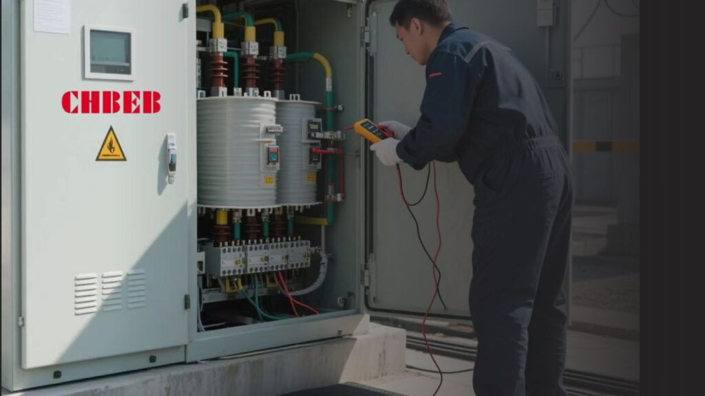
2. Equipment Inspection
Never assume new equipment is flawless. Always inspect:
- The transformer box for any shipping damage
- All accompanying parts and tools for completeness and condition
- The transformer’s oil level and check for any leaks
3. Voltage Testing
Before any work begins:
- Verify the voltage of incoming power lines
- Ensure all nearby circuits are de-energized and locked out
- Use proper voltage testing equipment and techniques
4. Clearance Verification
Adequate clearance is vital for safety and maintenance:
- Check local codes for required clearances around the transformer
- Ensure there’s enough space for ventilation and heat dissipation
- Verify accessibility for maintenance and emergency situations
Here’s a checklist table for pre-installation safety checks:
| Check Category | Specific Tasks | Importance |
|---|---|---|
| Site Assessment | Hazard identification, ground stability | Critical |
| Equipment Inspection | Damage check, parts inventory | High |
| Voltage Testing | Power line verification, circuit de-energizing | Critical |
| Clearance Verification | Space requirements, accessibility | High |
In my experience, one of the most overlooked aspects of pre-installation checks is considering future needs. I remember a case where a transformer was installed without accounting for the area’s growth potential. Within a few years, the space around it became cramped, making maintenance difficult and potentially unsafe.
Another crucial point is the importance of documenting these checks. I always insist on a detailed checklist that’s filled out and signed off before any installation begins. This not only ensures thoroughness but also provides a valuable record in case of future issues or audits.
Weather conditions should also be part of your pre-installation assessment. I once had to postpone an installation due to unexpected heavy rains. The wet conditions would have made the work unsafe and could have compromised the equipment. Always check the weather forecast and plan accordingly.
Communication with other utilities and stakeholders is another vital pre-installation step. In one project, we coordinated with the local gas company to mark their lines clearly before we began work. This extra step prevented potential disasters and showed the importance of inter-utility cooperation.
Lastly, don’t forget to review and understand the manufacturer’s installation guidelines thoroughly. Each transformer model may have specific requirements or precautions. I make it a point to have a team briefing where we go over these guidelines together, ensuring everyone is on the same page before we start the installation.
By meticulously following these pre-installation safety checks, we set the foundation for a safe and successful transformer box installation. Remember, in electrical work, preparation is not just about efficiency – it’s about preserving lives and preventing accidents.
Proper Grounding and Insulation: Ensuring Electrical Safety During Installation?
Have you ever wondered why some electrical installations fail despite using high-quality equipment? Often, the culprit is improper grounding or insulation. But how can you ensure these critical aspects are handled correctly during transformer box installation?
Proper grounding and insulation in transformer box installation involve creating a low-impedance path to earth, using appropriate insulating materials, and ensuring all connections are secure. This includes installing ground rods, using proper cable insulation, and following specific grounding techniques for different transformer types.
Exploring Grounding and Insulation Techniques
Let’s delve into the key aspects of grounding and insulation:
1. Grounding Basics
Proper grounding is crucial for safety and equipment protection:
- Install ground rods to the required depth (typically 8 feet or more)
- Use copper-clad or galvanized steel rods
- Ensure low ground resistance (usually less than 25 ohms)
I once worked on a project where inadequate grounding led to frequent equipment malfunctions. After improving the grounding system, these issues disappeared, highlighting the importance of this often-overlooked aspect.
2. Insulation Considerations
Proper insulation prevents electrical leakage and ensures safety:
- Use insulation materials rated for the voltage level
- Inspect all insulation for damage before installation
- Apply appropriate insulation techniques for connections and terminations
3. Grounding Techniques for Different Transformer Types
- Pad-mounted transformers: Connect to grounding grid or multiple ground rods
- Pole-mounted transformers: Use down leads connected to ground rods
- Vault-type transformers: Connect to building grounding system
4. Insulation Testing
Before energizing:
- Perform insulation resistance tests
- Check for any weak points in the insulation system
- Document all test results for future reference
Here’s a table summarizing grounding and insulation practices:
| Aspect | Key Practices | Importance |
|---|---|---|
| Grounding | Install ground rods, ensure low resistance | Critical |
| Insulation | Use rated materials, inspect for damage | High |
| Transformer-Specific Grounding | Follow type-specific techniques | Critical |
| Insulation Testing | Perform resistance tests, document results | High |
In my experience, one of the most common mistakes in grounding is relying on a single ground rod. I always recommend using multiple rods or a grounding grid for better performance. In one project, switching from a single rod to a three-rod system dramatically improved the grounding effectiveness and reduced electromagnetic interference issues.
Soil conditions play a crucial role in grounding effectiveness. I recall a challenging installation in an area with very rocky soil. We had to use chemical ground rods and a larger grounding grid to achieve the required resistance. It’s always important to consider local soil characteristics in your grounding design.
For insulation, climate considerations are crucial. In a project in a humid, coastal area, we had to use special moisture-resistant insulation materials to prevent degradation over time. This experience taught me the importance of adapting insulation choices to the specific environmental conditions of each installation site.
Another critical aspect is the bonding of metallic parts. I always ensure that all metal components of the transformer installation, including the tank, brackets, and nearby metallic structures, are properly bonded. This practice prevents dangerous touch potentials and ensures that fault currents have a clear path to ground.
Insulation coordination is a concept that’s often overlooked but crucial for system reliability. In one high-voltage installation, we had to carefully select insulation levels for various components to ensure they could withstand both normal operating voltages and potential surge voltages. This involved a detailed analysis of the entire system, from the transformer to connected equipment.
Lastly, it’s important to consider the impact of future changes on grounding and insulation. In a rapidly growing industrial area, we designed the grounding system with expansion in mind, allowing for easy upgrades as new equipment was added. This foresight saved considerable time and resources in subsequent years.
By paying close attention to grounding and insulation during transformer box installation, we not only ensure immediate safety but also lay the foundation for long-term reliability and efficiency of the electrical system. Remember, in electrical work, what you can’t see is often just as important as what you can.
Personal Protection and Equipment: Gearing Up for Safe Transformer Box Handling?
Have you ever wondered if you’re truly prepared to handle the risks involved in transformer box installation? Personal protection is not just about following rules; it’s about ensuring you return home safely every day. But what exactly do you need to stay safe?
Safe transformer box handling requires proper personal protective equipment (PPE) including insulated gloves, safety glasses, hard hats, and flame-resistant clothing. It also involves using the right tools, understanding voltage ratings, and following specific handling procedures for different transformer types.
Essential Personal Protection and Equipment
Let’s break down the key elements of personal protection and equipment:
1. Personal Protective Equipment (PPE)
The right PPE is your first line of defense:
- Insulated gloves rated for the voltage you’re working with
- Safety glasses or face shields to protect against arc flashes
- Hard hats to guard against falling objects
- Flame-resistant clothing to protect from potential fires or arc flashes
I once witnessed a near-miss where a worker’s non-rated gloves almost led to a severe shock. Since then, I’ve been adamant about proper PPE use and regular inspection of safety gear.
2. Proper Tools and Equipment
Using the right tools is crucial for safety and efficiency:
- Insulated tools rated for the voltage level
- Properly calibrated voltage testers and multimeters
- Appropriate lifting and handling equipment for transformer movement
3. Understanding Voltage Ratings
Knowledge is a form of protection:
- Ensure all team members understand the voltage ratings involved
- Use clear labeling and signage to indicate voltage levels
- Provide regular training on voltage safety and awareness
4. Specific Handling Procedures
Different transformer types require different handling approaches:
- Pad-mounted transformers: Use proper lifting techniques and equipment
- Pole-mounted transformers: Ensure secure mounting and proper balance
- Dry-type transformers: Handle with care to prevent damage to windings
Here’s a table summarizing key PPE and equipment:
| Category | Items | Purpose |
|---|---|---|
| Head Protection | Hard hat, safety glasses | Protect against falling objects and debris |
| Hand Protection | Insulated gloves, tool handles | Prevent electrical shock |
| Body Protection | Flame-resistant clothing | Guard against arc flash and fire |
| Foot Protection | Insulated safety boots | Provide electrical insulation and foot protection |
| Tools | Insulated tools, voltage testers | Ensure safe handling of electrical components |
In my years of experience, I’ve learned that PPE is only effective if it’s properly maintained and regularly inspected. I implement a strict PPE inspection routine in all my projects. Once, during a routine check, we discovered a tiny hole in a pair of insulated gloves. Replacing them potentially prevented a serious accident.
Another crucial aspect of personal protection is understanding and respecting the limits of your PPE. I always emphasize to my teams that PPE is the last line of defense, not a license to take unnecessary risks. In one training session, we demonstrated the effects of arc flash on different types of PPE. This visual demonstration dramatically improved the team’s appreciation for proper safety gear.
Proper lifting and handling techniques are often overlooked in transformer installation. I recall a project where we implemented a comprehensive lifting protocol, including the use of mechanical aids and team lifting techniques. This not only improved safety but also reduced the risk of equipment damage during installation.
Climate considerations also play a role in PPE selection. In a project in an extremely hot climate, we had to carefully select PPE that provided necessary protection without causing heat stress. This involved using breathable, flame-resistant fabrics and implementing work-rest cycles to prevent overheating.
Communication is another vital aspect of personal protection. I always insist on clear communication protocols, especially when working with high voltages. Using standardized hand signals and radio communication has proven invaluable in noisy work environments or when visual contact is limited.
Lastly, I can’t stress enough the importance of creating a culture of safety. In every project, I encourage team members to speak up about safety concerns without fear of reprisal. This open communication has led to numerous improvements in our safety practices and has prevented potential accidents.
By prioritizing personal protection and using the right equipment, we not only ensure individual safety but also contribute to a safer work environment for everyone involved in transformer box handling. Remember, in electrical work, your PPE is not just equipment – it’s your lifeline.
Environmental Considerations: Adapting Installation Practices to Different Settings?
Have you ever faced unexpected challenges while installing a transformer box due to environmental factors? Different settings can dramatically affect installation practices, but how do you adapt to ensure safety and efficiency in varied environments?
Adapting transformer box installation to different environments involves considering factors like climate, terrain, wildlife, and local regulations. This may include using specialized equipment for extreme temperatures, implementing flood protection measures, or modifying installation techniques for urban or rural settings.
Adapting to Various Environmental Conditions
Let’s explore how to adapt installation practices to different settings:
1. Climate Considerations
Different climates require different approaches:
- Hot climates: Use enhanced cooling systems, heat-resistant materials
- Cold climates: Implement freeze protection, use cold-weather lubricants
- Humid environments: Apply additional corrosion protection, moisture-resistant insulation
I once worked on a project in a tropical climate where standard transformers were overheating. We had to redesign the cooling system and use special heat-resistant insulation to ensure reliable operation.
2. Terrain Challenges
Adapting to various terrains is crucial:
- Mountainous areas: Consider seismic activity, use reinforced foundations
- Coastal regions: Implement salt-spray protection, elevated installations
- Urban settings: Focus on space efficiency, noise reduction
3. Wildlife and Vegetation
Protecting transformers from nature (and vice versa):
- Install wildlife guards to prevent animal intrusions
- Implement vegetation management to prevent interference
- Use eco-friendly materials and practices where possible
4. Local Regulations and Standards
Always adhere to local requirements:
- Research and comply with local environmental regulations
- Adapt installation practices to meet regional standards
- Consider community concerns and aesthetic requirements
Here’s a table summarizing environmental adaptations:
| Environment | Key Considerations | Adaptation Strategies |
|---|---|---|
| Hot Climate | Overheating risk | Enhanced cooling, heat-resistant materials |
| Cold Climate | Freezing issues | Freeze protection, cold-rated components |
| Coastal Areas | Corrosion, flooding | Corrosion-resistant materials, elevated installation |
| Urban Settings | Space constraints, noise | Compact designs, sound insulation |
| Wildlife-Rich Areas | Animal interference | Wildlife guards, strategic placement |
In my experience, one of the most challenging aspects of environmental adaptation is balancing technical requirements with ecological considerations. In a project near a protected wetland, we had to completely rethink our installation approach. We used biodegradable transformer oil and implemented an advanced containment system to prevent any potential environmental contamination.
Extreme weather events pose another significant challenge. I recall a project in a hurricane-prone area where we had to design a transformer installation that could withstand Category 5 winds. This involved not just reinforcing the transformer itself, but also redesigning the entire mounting structure and implementing a rapid disconnect system for emergency situations.
In urban environments, noise reduction often becomes a primary concern. During an installation in a densely populated area, we employed advanced sound-dampening techniques, including specially designed enclosures and vibration isolation mounts. The result was a transformer installation that was barely audible even at close range.
Adapting to high-altitude environments presents unique challenges. In a mountain installation project, we had to account for reduced air density affecting cooling efficiency. This led us to oversize the cooling system and use special insulating materials designed for high-altitude operations.
In areas with extreme temperature fluctuations, material selection becomes crucial. I worked on a project in a desert region where daytime temperatures soared, but nights were surprisingly cold. We had to select materials and design expansion joints that could handle this daily thermal cycling without compromising the integrity of the installation.
Lastly, it’s important to consider the visual impact of transformer installations, especially in scenic or historically significant areas. In one project near a historic district, we worked closely with local architects to design a transformer enclosure that blended seamlessly with the surrounding architecture. This not only satisfied local regulations but also gained community support for the project.
Adapting transformer box installation practices to different environmental settings is not just about overcoming challenges – it’s about creating solutions that harmonize with the local environment. By carefully considering climate, terrain, wildlife, and local regulations, we can ensure that our installations are not only safe and efficient but also respectful of the environments they’re placed in. Remember, a successful installation is one that works well and fits well into its surroundings.
Post-Installation Safety Measures: Securing and Maintaining Transformer Boxes?
Have you ever wondered what happens after a transformer box is installed? The job isn’t over once the installation is complete. In fact, post-installation safety measures are crucial for long-term reliability and safety. But what exactly should be done to secure and maintain these vital components of our electrical infrastructure?
Post-installation safety for transformer boxes involves regular inspections, proper fencing and signage, ongoing maintenance, and emergency response planning. These measures ensure the transformer remains secure, operates efficiently, and poses minimal risk to the public and environment over its entire lifespan.
Essential Post-Installation Safety Measures
Let’s explore the key aspects of securing and maintaining transformer boxes after installation:
1. Physical Security
Protecting the transformer from unauthorized access is crucial:
- Install sturdy fencing or enclosures around the transformer
- Use tamper-resistant locks and security systems
- Implement proper lighting to deter vandalism
I once worked on a project where we underestimated the need for physical security. Within months, we had incidents of copper theft. This experience taught me the importance of robust security measures, even in seemingly low-risk areas.
2. Signage and Warnings
Clear communication of dangers is essential:
- Place visible "Danger – High Voltage" signs
- Include emergency contact information
- Use multilingual signage in diverse communities
3. Regular Inspections
Ongoing checks help prevent issues:
- Conduct monthly visual inspections
- Perform annual thorough examinations
- Use thermal imaging to detect hotspots
4. Maintenance Procedures
Proper upkeep ensures longevity and safety:
- Regularly test and maintain oil levels and quality
- Clean and tighten connections
- Update and replace components as needed
Here’s a table outlining post-installation safety measures:
| Measure | Frequency | Importance |
|---|---|---|
| Physical Security Check | Monthly | High |
| Signage Inspection | Quarterly | Medium |
| Visual Inspection | Monthly | High |
| Thermal Imaging | Annually | High |
| Oil Testing | Annually | Critical |
| Connection Tightening | Annually | High |
In my experience, one of the most overlooked aspects of post-installation safety is community education. I remember a project where we implemented a comprehensive community outreach program, educating local residents about transformer safety. This not only reduced incidents of tampering but also improved community relations and safety awareness.
Emergency response planning is another crucial element of post-installation safety. In one memorable case, we worked with local emergency services to develop a detailed response plan for transformer-related incidents. This included training sessions for first responders on how to safely approach and handle transformer emergencies.
Environmental considerations continue to be important even after installation. I’ve been involved in projects where we implemented advanced oil containment systems and used biodegradable transformer oils to minimize environmental risks. Regular checks of these systems are crucial to ensure they remain effective over time.
The impact of weather on transformer safety cannot be overstated. In areas prone to flooding, we often implement elevated designs and water-resistant features. I recall a project in a flood-prone region where we installed water level sensors and automatic shut-off systems to prevent damage and potential hazards during flood events.
Technological advancements have greatly enhanced our ability to monitor and maintain transformer safety. In recent years, I’ve been implementing smart monitoring systems that provide real-time data on transformer performance and safety parameters. These systems can alert maintenance teams to potential issues before they become critical, significantly improving overall safety and reliability.
Vegetation management is an often-overlooked aspect of post-installation safety, especially for outdoor transformer boxes. I always include a vegetation management plan in our maintenance procedures. Overgrown vegetation can not only interfere with transformer operation but also pose fire risks and hinder emergency access.
Lastly, it’s crucial to maintain up-to-date documentation of all safety measures and maintenance activities. I insist on detailed record-keeping for all transformer installations. This not only helps in tracking the transformer’s history but also proves invaluable during audits or in the event of any incidents.
By implementing comprehensive post-installation safety measures, we ensure that transformer boxes remain secure, efficient, and safe throughout their operational life. Remember, the safety of a transformer installation is an ongoing commitment, not a one-time task.
Conclusion
Electrical transformer box safety is crucial throughout the installation process and beyond. From pre-installation checks to post-installation maintenance, each step plays a vital role in ensuring safety, efficiency, and longevity. By following these guidelines and best practices, we can create safer and more reliable electrical infrastructure.
What Is an Electrical Transformer Box and Why It Matters?
An electrical transformer box is a protective enclosure that houses a transformer, which changes voltage levels in electrical power distribution systems. These boxes are essential for safely stepping down high voltage electricity from power lines to usable levels for homes and businesses.
Have you ever noticed those large metal boxes in your neighborhood and wondered what they do? These mysterious containers play a crucial role in powering our homes and businesses, but many people don’t know what they are or how they work.
In this article, I’ll explain what electrical transformer boxes are, how they work, and why they’re so important for our power infrastructure. Whether you’re a curious homeowner or someone interested in electrical systems, this guide will help you understand these vital components of our electrical grid.
Electrical Transformer Box Function and Role in Power Systems
Have you ever wondered how the high-voltage electricity from power plants becomes safe to use in your home? The answer lies in those unassuming metal boxes you see around your neighborhood. But what exactly do these transformer boxes do?
Electrical transformer boxes house transformers that step down high voltage electricity to lower, safer levels for local use. They act as crucial intermediaries between the power grid and end-users, ensuring efficient power distribution and protecting equipment from high voltages.
Understanding Transformer Boxes
Let’s break down the key aspects of electrical transformer boxes:
Primary Function
The main job of a transformer box is to protect and house the transformer inside. This transformer does the critical work of changing voltage levels. Here’s how it works:
- High voltage electricity enters the transformer
- The transformer reduces the voltage to a safe level
- Lower voltage electricity exits for use in homes and businesses
I once explained this concept to a group of students using a water analogy. I compared high voltage to water at high pressure in main pipes, and the transformer to a pressure reducer for home use.
Importance in Power Systems
Transformer boxes play several crucial roles:
- Safety: They isolate high voltage equipment from public access
- Protection: They shield transformers from weather and physical damage
- Efficiency: They allow for efficient power distribution over long distances
- Voltage Regulation: They help maintain consistent voltage levels in local areas
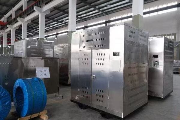
Components of a Transformer Box
A typical transformer box contains:
- The transformer itself
- Insulating oil or dry-type insulation
- Cooling systems (for larger units)
- Protective devices like fuses or circuit breakers
- Bushings for electrical connections
Here’s a table showing typical voltage levels in power distribution:
| Stage | Voltage Level |
|---|---|
| Transmission Lines | 69,000 – 765,000 V |
| Primary Distribution | 4,000 – 34,500 V |
| Secondary Distribution (to homes) | 120/240 V |
In my experience, the importance of transformer boxes is often underappreciated. I remember a project where we were upgrading the power infrastructure in an older neighborhood. The residents were amazed to learn how these unassuming boxes were crucial to delivering stable power to their homes.
One interesting aspect of transformer boxes is their role in power quality management. In urban areas with high power demand, we often install multiple smaller transformer boxes instead of one large unit. This distributed approach helps maintain voltage stability and reduces the impact of any single transformer failure.
Another crucial function of transformer boxes is their role in electrical isolation. They create a barrier between the high-voltage distribution system and low-voltage consumer networks. This isolation is vital for safety and helps prevent issues in one part of the grid from affecting others.
Transformer boxes also play a key role in energy loss reduction. By stepping down voltage close to the point of use, they minimize the distance that low-voltage (and thus higher current) electricity needs to travel, reducing overall system losses.
As our power needs evolve, so do transformer boxes. In recent years, I’ve worked on projects integrating smart technology into these units. These smart transformer boxes can communicate with the grid, adjust to changing loads, and even help integrate renewable energy sources.
Understanding the basics of electrical transformer boxes helps us appreciate the complex infrastructure that powers our daily lives. These unassuming metal containers are the unsung heroes of our electrical system, working silently to ensure we have safe, reliable power at our fingertips.
Inside an Electrical Transformer Box: Key Components Explained
Have you ever wondered what’s inside those mysterious electrical boxes in your neighborhood? The inner workings of a transformer box might seem complex, but understanding its key components can demystify this crucial part of our power infrastructure.
Inside an electrical transformer box, you’ll find the transformer itself, along with insulation, cooling systems, and protective devices. The transformer core and windings are the heart of the system, working together to change voltage levels. Other components ensure safe, efficient operation.
Exploring the Components of a Transformer Box
Let’s dive into the key parts inside a transformer box and how they function:
1. The Transformer Core
The core is the heart of the transformer:
- Made of thin, laminated sheets of silicon steel
- Provides a path for magnetic flux
- Shapes can vary (e.g., core-type or shell-type)
I once used a simple demonstration to explain the core’s function. I wrapped a wire around a nail and connected it to a battery. The nail became magnetized, showing how electric current creates a magnetic field in the core.
2. Windings
Transformers have two sets of windings:
- Primary Winding: Connected to the incoming high-voltage power
- Secondary Winding: Delivers the stepped-down voltage
- Made of insulated copper or aluminum wire
The relationship between these windings determines the voltage change. Here’s a simple formula:Vp / Vs = Np / Ns1
Where:
- Vp = Primary voltage
- Vs = Secondary voltage
- Np = Number of turns in primary winding
- Ns = Number of turns in secondary winding
3. Insulating Medium
Transformers use either oil or air for insulation:
- Oil-filled: Better cooling and insulation, used in larger units
- Dry-type: Uses air and solid insulation, safer for indoor use
4. Cooling System
Cooling is crucial for efficient operation:
- Oil-filled units use the oil for cooling
- Larger units may have radiators or fans
- Dry-type units rely on air circulation
5. Bushings
Bushings are the connection points:
- Allow electrical connections to enter and exit the transformer
- Insulated to prevent arcing
6. Protective Devices
Safety components include:
- Fuses or circuit breakers
- Pressure relief devices
- Temperature monitors
Here’s a table summarizing the key components:
| Component | Function | Importance |
|---|---|---|
| Core | Magnetic flux path | Enables energy transfer |
| Windings | Voltage transformation | Determines voltage change |
| Insulation | Electrical isolation | Prevents short circuits |
| Cooling System | Heat management | Ensures efficient operation |
| Bushings | Electrical connections | Allows safe power transfer |
| Protective Devices | Safety and monitoring | Prevents damage and failures |
In my experience, understanding these components is crucial for effective transformer management. I recall a project where we were troubleshooting a faulty transformer. By methodically checking each component, we identified a problem with the insulation that wasn’t apparent from external symptoms.
One interesting aspect of transformer design is the balance between efficiency and size. In urban areas with limited space, we often need to use more compact designs. This might involve using higher-grade core materials or more efficient cooling systems to maintain performance in a smaller package.
The choice of insulating medium is another critical decision. While oil-filled transformers are more common in large outdoor units, dry-type transformers are gaining popularity, especially in environmentally sensitive areas. I worked on a project near a water source where we opted for dry-type units to eliminate the risk of oil leaks.
Advancements in materials science are also changing transformer design. For instance, amorphous metal cores, while more expensive, can significantly reduce energy losses. In one energy-efficiency project, we replaced old transformers with these high-efficiency models, resulting in substantial long-term energy savings.
The protective devices in transformer boxes are becoming increasingly sophisticated. Modern units often include smart monitoring systems that can detect potential issues before they become critical. This predictive maintenance approach has revolutionized how we manage transformer fleets, allowing for more efficient and proactive maintenance schedules.
Understanding the inner workings of transformer boxes helps us appreciate the engineering that goes into these crucial components of our power infrastructure. Each part plays a vital role in ensuring we have safe, reliable electricity in our homes and businesses.
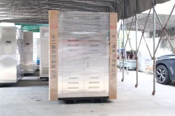
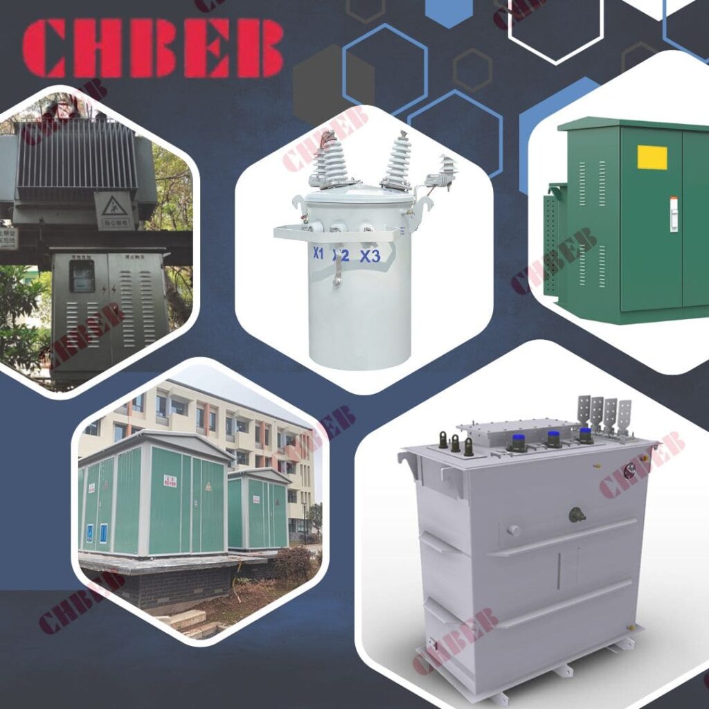
Types of Electrical Transformer Boxes and Where They’re Used
Have you ever noticed that not all electrical transformer boxes look the same? The variety in shapes, sizes, and locations of these boxes isn’t random. Each configuration serves a specific purpose in our power distribution system. But what are these different types, and why are they placed where they are?
Electrical transformer boxes come in various configurations, including pole-mounted, pad-mounted, and vault-type. Their design and location depend on factors like voltage levels, environmental conditions, and urban planning considerations. Understanding these types helps in recognizing their role in different settings.
Exploring Transformer Box Types and Locations
Let’s break down the main types of transformer boxes and where you might find them:
1. Pole-Mounted Transformers2
These are the most common in many areas:
- Mounted on utility poles
- Typically used in residential areas
- Handle voltages up to about 34,500 volts
I remember a project in a rural area where pole-mounted transformers were the best option due to their cost-effectiveness and ease of installation in areas with overhead power lines.
2. Pad-Mounted Transformers
These are becoming more common, especially in newer developments:
- Installed on concrete pads at ground level
- Often used in residential and light commercial areas
- Can handle higher voltages than pole-mounted units
3. Vault-Type Transformers
These are used in dense urban areas:
- Installed underground in vaults
- Common in city centers and high-rise buildings
- Can handle very high voltages and capacities
4. Submersible Transformers
Designed for flood-prone areas:
- Can operate while submerged
- Used in areas with high water tables or flood risks
Here’s a comparison table of these transformer types:
| Type | Typical Location | Voltage Range | Advantages |
|---|---|---|---|
| Pole-Mounted | Residential areas | Up to 34.5 kV | Cost-effective, easy maintenance |
| Pad-Mounted | Suburban areas | Up to 35 kV | Aesthetically pleasing, safer |
| Vault-Type | Urban centers | Up to 35 kV | Space-saving, protected from elements |
| Submersible | Flood-prone areas | Up to 35 kV | Operable in flooded conditions |
The choice of transformer box type often depends on various factors. In one urban redevelopment project I worked on, we transitioned from pole-mounted to pad-mounted transformers. This not only improved the area’s aesthetics but also allowed for easier maintenance access.
Location considerations go beyond just aesthetics or convenience. In areas prone to severe weather, we often opt for more robust designs. I recall a coastal project where we used specially designed pad-mounted transformers with enhanced corrosion resistance to withstand the salt air.
Urban planning plays a significant role in transformer box placement. In dense city areas, underground vault-type transformers are often the only viable option due to space constraints. However, these require careful planning for ventilation and access.
Environmental factors also influence transformer box selection. In environmentally sensitive areas, we might choose dry-type transformers over oil-filled ones to minimize the risk of contamination in case of a leak.
The trend towards renewable energy integration is also affecting transformer box design and placement. In areas with high solar panel adoption, we’re seeing more bi-directional transformers that can handle power flow in both directions.
Another interesting development is the use of modular transformer boxes. These allow for easier upgrades and replacements as power needs change. In rapidly growing areas, this flexibility can be a significant advantage.
Safety considerations are paramount in transformer box placement. For pad-mounted units in public areas, we implement various security measures to prevent unauthorized access while still allowing for emergency response.
Understanding the types and locations of transformer boxes helps us appreciate the thought and planning that goes into our power distribution systems. Each type has its place in ensuring we have reliable, efficient, and safe electricity delivery in various environments.
Safety Precautions Around Electrical Transformer Boxes
Have you ever wondered about the safety of those electrical boxes in your neighborhood? While transformer boxes are designed to be safe, they still contain high-voltage equipment. Understanding the proper precautions around these boxes is crucial for public safety. But what exactly should you know to stay safe?
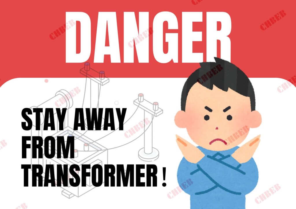
Safety around transformer boxes involves maintaining a safe distance, avoiding tampering, and reporting any damage or suspicious activity. Key precautions include never touching or opening the boxes, keeping the area clear of debris, and educating children about potential dangers. Proper awareness can prevent accidents and ensure public safety.
Essential Safety Precautions for Transformer Boxes
Let’s explore the key safety measures and best practices around transformer boxes:
1. Maintain a Safe Distance
- Stay at least 3 meters (10 feet) away from transformer boxes
- Never climb on or sit near them
I once witnessed a close call where a child was playing near a transformer box. It reinforced the importance of educating the community about these dangers.
2. Never Touch or Open
- Transformer boxes should only be opened by qualified personnel
- Even the exterior can be energized under fault conditions
3. Report Damage or Suspicious Activity
- Contact your local utility company if you notice:
- Unusual noises
- Oil leaks
- Physical damage
- Signs of tampering
4. Keep the Area Clear
- Don’t plant trees or shrubs too close to transformer boxes
- Ensure easy access for utility workers
5. Be Cautious During Floods
- Stay away from submerged transformer boxes
- Water can conduct electricity
Here’s a table summarizing key safety dos and don’ts:
| Do | Don’t |
|---|---|
| Report damage | Touch or open the box |
| Keep a safe distance | Plant vegetation too close |
| Educate others about safety | Store items on or against the box |
| Call utility for concerns | Attempt repairs yourself |
| Clear snow carefully | Use it as a play area |
In my years working with electrical systems, I’ve seen the consequences of safety negligence. One incident that stands out involved a landscaper who accidentally damaged a pad-mounted transformer while digging. It resulted in a power outage and could have been much worse. This experience underscores the importance of awareness and caution around these facilities.
Public education is crucial for transformer box safety. In one community project, we implemented a school outreach program to teach children about electrical safety. The program included age-appropriate lessons and even a mascot to make the message more engaging.
For homeowners and businesses near transformer boxes, we often provide guidelines on landscaping and snow removal. Proper clearance is essential not just for safety but also for maintenance access. I recall a situation where overgrown vegetation delayed an emergency repair, highlighting the importance of keeping these areas clear.
Emergency preparedness is another critical aspect of transformer box safety. In areas prone to flooding, we work with local emergency services to develop response plans. This includes protocols for dealing with submerged transformers and ensuring public safety during flood events.
The rise of electric vehicles has introduced new considerations for transformer box safety. In areas with high EV adoption, we’re seeing increased loads on residential transformers. This has led to new guidelines for EV charging installations to prevent overloading and potential safety issues.
Vandalism and theft are unfortunately common issues with transformer boxes. We’ve implemented various security measures, from tamper-proof designs to surveillance systems in high-risk areas. However, community vigilance remains one of the most effective deterrents.
Lastly, it’s important to address the misconceptions about EMF (Electromagnetic Fields) from transformer boxes. While these boxes do emit EMFs, the levels are generally well below safety limits at the typical distances people maintain from them. We often conduct EMF measurements to reassure concerned residents.
By following these safety precautions and best practices, we can ensure that transformer boxes continue to serve their vital role in our power distribution system without posing undue risks to the public. Remember, when it comes to electrical equipment, it’s always better to err on the side of caution.
Transformer Box Maintenance, Costs & Efficiency Upgrades
Have you ever wondered how those electrical transformer boxes in your neighborhood stay functional year after year? Proper maintenance is key to their longevity and efficiency. But what goes into keeping these crucial components of our power grid in top shape?
Maintaining transformer boxes involves regular inspections, timely repairs, and efficiency upgrades. Key activities include checking for oil leaks, monitoring temperature, cleaning cooling systems, and updating insulation. Proper maintenance ensures reliable power distribution, extends equipment life, and improves overall energy efficiency.
Essential Maintenance and Efficiency Practices
Let’s explore the key aspects of maintaining and optimizing transformer boxes:
1. Regular Inspections
- Visual checks for damage or leaks
- Thermal imaging to detect hot spots
- Oil level and quality checks
I once discovered a small oil leak during a routine inspection that could have led to a major failure if left unchecked. This experience reinforced the importance of regular, thorough inspections.
2. Cleaning and Cooling System Maintenance
- Clearing debris from cooling fins
- Cleaning or replacing air filters in dry-type units
- Ensuring proper oil circulation in oil-filled transformers
3. Electrical Testing
- Insulation resistance tests
- Turn ratio tests
- Power factor testing
4. Load Management
- Monitoring and balancing loads
- Upgrading capacity when necessary
5. Efficiency Upgrades
- Replacing old units with high-efficiency models
- Implementing smart monitoring systems
Here’s a table outlining a basic maintenance schedule:
| Maintenance Task | Frequency | Importance |
|---|---|---|
| Visual Inspection | Monthly | High |
| Oil Testing | Annually | Critical |
| Thermal Imaging | Quarterly | High |
| Electrical Testing | Every 3-5 years | Critical |
| Load Assessment | Ongoing | High |
In my experience, proactive maintenance is key to preventing unexpected failures. I recall a project where we implemented a comprehensive maintenance program for a utility company. Within two years, we saw a 40% reduction in transformer-related outages.
One often overlooked aspect of transformer maintenance is the impact of environmental factors. In coastal areas, for instance, salt air can accelerate corrosion. I worked on a project where we had to develop a special maintenance routine, including more frequent cleaning and application of protective coatings, to combat this issue.
Efficiency improvements can have a significant impact on both performance and operating costs. In one case, we replaced a group of older transformers with new, high-efficiency models. The energy savings alone paid for the upgrade within five years, not to mention the improved reliability.
Load management is becoming increasingly important, especially with the growing adoption of electric vehicles. I’ve been involved in projects where we’ve had to upgrade residential transformers to handle the increased load from EV charging. Proper load monitoring and timely upgrades are crucial to prevent overloading and potential failures.
The integration of smart technology is revolutionizing transformer maintenance. In recent projects, we’ve installed sensors that provide real-time data on transformer health. This allows for predictive maintenance, where potential issues can be addressed before they lead to failures.
Another important consideration is the management of transformer oil. Regular oil testing can reveal a lot about the health of a transformer. I remember a case where dissolved gas analysis of the oil indicated an developing internal fault, allowing us to address the issue before it caused a failure.
Noise reduction is an often-overlooked aspect of transformer maintenance, especially in residential areas. We’ve implemented various noise reduction techniques, from improved insulation to active noise cancellation systems, to address community concerns.
Lastly, it’s crucial to consider the end-of-life management of transformer boxes. Proper disposal or recycling of old units, especially those containing oil, is essential for environmental protection. I’ve been involved in developing recycling programs that recover valuable materials from decommissioned transformers.
Effective maintenance and efficiency practices not only extend the life of transformer boxes but also contribute to a more reliable and efficient power distribution system. By staying proactive and embracing new technologies, we can ensure these critical components continue to serve our communities effectively for years to come.
Conclusion & Next Steps: Choosing the Right Transformer Box
Electrical transformer boxes are crucial components of our power distribution system. They safely step down voltage for local use, come in various types for different settings, and require careful maintenance. Understanding their function, safety precautions, and maintenance needs helps us appreciate and protect these vital parts of our electrical infrastructure.
Need help selecting the right electrical transformer box for your project? Contact CHBEB today for a tailored solution or download our full transformer catalog here.
Are you struggling to determine the right size for your power pole transformer? Choosing the wrong capacity can lead to inefficiency, increased costs, and even safety hazards. Many engineers and planners face this challenge when designing or upgrading electrical distribution systems.
Proper power pole transformer sizing involves calculating peak and average load requirements, considering factors like distance, load type, and climate. The right size ensures efficient power distribution, prevents overloading, and reduces energy losses. It’s crucial to balance current needs with future growth projections.
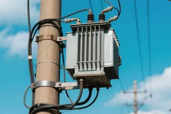
In this article, I’ll guide you through the process of selecting the right transformer capacity for your distribution line. We’ll explore the factors that influence sizing, common mistakes to avoid, and provide practical examples to help you make informed decisions. Whether you’re a seasoned engineer or new to the field, this guide will help you optimize your power distribution system.
Why Proper Sizing Matters for Safety and Efficiency?
Have you ever wondered why some transformers fail prematurely or why your electricity bill seems higher than it should be? The answer often lies in improper transformer sizing. But why exactly is getting the right size so crucial?
Proper transformer sizing is essential for both safety and efficiency. Oversized transformers waste energy and increase costs, while undersized ones risk overheating and failure. Correct sizing ensures optimal performance, reduces energy losses, extends equipment life, and maintains voltage stability.

The Importance of Proper Transformer Sizing
Let’s delve into why sizing matters so much:
Safety Considerations
-
Overheating Prevention:
- Undersized transformers can overheat under heavy loads
- This can lead to insulation breakdown and potential fires
-
Voltage Stability:
- Properly sized transformers maintain stable voltage levels
- This protects connected equipment from damage
I once investigated a transformer failure that was caused by chronic undersizing. The transformer had been running hot for months, eventually leading to a catastrophic breakdown. This incident not only caused a prolonged power outage but also posed significant safety risks.
Efficiency Factors
-
Energy Losses:
- Oversized transformers have higher core losses
- Undersized units suffer from increased copper losses
-
Cost Implications:
- Right-sized transformers optimize initial investment
- They also reduce long-term operating costs
-
Lifespan:
- Properly sized units have longer operational lives
- This reduces replacement frequency and associated costs
Here’s a table comparing the effects of different sizing scenarios:
| Sizing | Safety Impact | Efficiency Impact | Cost Impact |
|---|---|---|---|
| Undersized | High risk of failure | High copper losses | Lower initial cost, high operating cost |
| Properly Sized | Optimal safety | Balanced losses | Optimal lifecycle cost |
| Oversized | Low risk of failure | High core losses | High initial cost, higher than necessary operating cost |
In my experience, the consequences of improper sizing can be far-reaching. I recall a project where an oversized transformer was installed in a small commercial area. While it seemed like a "safe" choice, the excess capacity led to significant energy waste. Over five years, the additional energy losses cost more than the price of the transformer itself.
Another aspect often overlooked is the impact of sizing on power quality. In one residential area, I found that undersized transformers were causing voltage fluctuations during peak hours. This not only affected the residents’ quality of life but also damaged sensitive electronic equipment.
Proper sizing also plays a crucial role in future-proofing your power distribution system. I always advise considering potential load growth when sizing transformers. In a rapidly developing suburban area, we chose a slightly larger transformer capacity, anticipating future demand. This foresight saved the utility company from costly upgrades just a few years later.
It’s also worth noting the environmental impact of transformer sizing. Energy-efficient transformers not only save money but also reduce carbon footprint. In a recent project, we calculated that right-sizing transformers across a small city could reduce CO2 emissions by hundreds of tons annually.
Lastly, proper sizing is crucial for maintaining grid stability, especially with the increasing integration of renewable energy sources. I’ve worked on projects where we had to carefully size transformers to handle the variable output from solar and wind installations while maintaining stable voltage for conventional loads.
By understanding the importance of proper transformer sizing, we can design safer, more efficient, and more cost-effective power distribution systems. Remember, the right size isn’t just about meeting current needs – it’s about balancing present demands with future growth and overall system efficiency.
Understanding kVA Ratings and Load Demand?
Have you ever wondered what those kVA numbers on transformers mean? Or how to determine the right capacity for your power needs? Understanding kVA ratings and load demand is crucial for proper transformer sizing, but many find these concepts confusing.
kVA (kilovolt-amperes) ratings indicate a transformer’s capacity to deliver power. Load demand refers to the actual power required by connected devices. Proper sizing involves matching the kVA rating to the expected peak load demand, considering factors like load diversity and future growth.
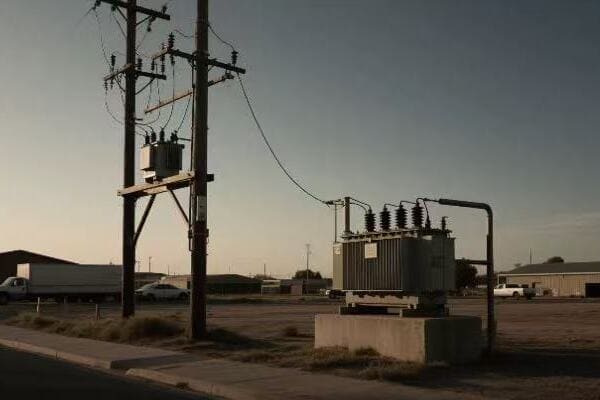
Diving into kVA Ratings and Load Demand
Let’s break down these important concepts:
Understanding kVA Ratings
-
Definition:
- kVA stands for kilovolt-amperes
- It’s a measure of apparent power
-
Relationship to Power:
- kVA = Voltage (kV) × Current (A)
- For single-phase: kVA = kW ÷ Power Factor
- For three-phase: kVA = (√3 × kW) ÷ Power Factor
I often use a water analogy to explain kVA. If you think of electricity as water in a pipe, kVA is like the pipe’s capacity – how much water it can potentially carry.
Load Demand Basics
-
Definition:
- Actual power required by connected devices
- Measured in kW (kilowatts)
-
Types of Load:
- Continuous Load: Constant power draw
- Intermittent Load: Varies over time
- Peak Load: Maximum power demand at any given time
Relationship Between kVA and Load
- Transformer kVA rating should exceed the maximum expected load
- Consider power factor: kW = kVA × Power Factor
Here’s a table showing typical kVA ratings and their applications:
| kVA Rating | Typical Application |
|---|---|
| 5-25 kVA | Residential areas |
| 25-100 kVA | Small commercial |
| 100-500 kVA | Large commercial/small industrial |
| 500+ kVA | Large industrial/substations |
In my experience, one of the most common mistakes in transformer sizing is not accounting for the difference between connected load and actual demand. I recall a project where a factory’s connected load was 1000 kVA, but the actual peak demand never exceeded 600 kVA. Sizing the transformer based on connected load would have led to significant oversizing and inefficiency.
Load diversity is another crucial concept in understanding demand. Not all connected devices operate simultaneously at full capacity. I once worked on a residential development where considering load diversity allowed us to reduce the transformer size by 30% without compromising reliability.
Power factor correction is also vital in relating kVA to actual power needs. In an industrial setting, we implemented power factor correction capacitors, which allowed for a smaller transformer while still meeting the facility’s power requirements.
Future growth projection is a key aspect of load demand analysis. I always advise clients to consider a 5-10 year growth plan when sizing transformers. In a rapidly growing tech park, we sized transformers with a 25% capacity buffer, which proved crucial as new businesses moved in over the next few years.
Understanding load profiles is essential for accurate sizing. I use data logging tools to capture load variations over time. In one commercial complex, this approach revealed that peak demand occurred for only a few hours each day, allowing for more precise transformer sizing.
Harmonic loads present a unique challenge in kVA calculations. In a data center project, we had to oversize transformers slightly to account for harmonic heating effects from non-linear loads like computer power supplies.
Lastly, it’s important to consider the impact of energy efficiency initiatives on load demand. In a recent retrofit project, upgrading to LED lighting and high-efficiency HVAC systems significantly reduced the load, allowing for downsizing of the transformer during replacement.
By thoroughly understanding kVA ratings and load demand, we can ensure that transformers are sized correctly, balancing efficiency, cost, and reliability. Remember, the goal is not just to meet current needs but to provide a flexible, efficient solution for years to come.
Factors That Influence Sizing: Distance, Load Type, Climate?
Have you ever wondered why transformers of the same kVA rating might be used differently in various locations? The answer lies in the numerous factors that influence transformer sizing beyond just the load demand. But what are these factors, and how do they affect our sizing decisions?
Transformer sizing is influenced by factors like distance from the source, types of loads served, and local climate conditions. Longer distances may require larger transformers to compensate for voltage drop. Different load types (residential, industrial) have varying demand patterns. Climate affects cooling efficiency and load variations.
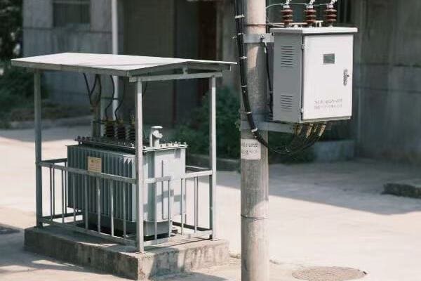
Exploring Key Factors in Transformer Sizing
Let’s delve into the main factors that influence transformer sizing:
1. Distance from Power Source
-
Voltage Drop Considerations:
- Longer distances lead to higher voltage drops
- May require larger transformers to maintain voltage stability
-
Line Loss Compensation:
- Increased size can help offset transmission losses
I once worked on a rural electrification project where we had to significantly upsize transformers due to the long distances involved. The voltage drop over several miles was substantial, and larger transformers were necessary to maintain proper voltage at the point of use.
2. Load Type and Characteristics
-
Residential vs. Commercial vs. Industrial:
- Each has different load patterns and peak demands
-
Load Diversity:
- More diverse loads often allow for smaller transformers
-
Power Factor:
- Low power factor loads may require larger transformers
3. Climate and Environmental Conditions
-
Ambient Temperature:
- Higher temperatures reduce transformer cooling efficiency
- May necessitate larger units or additional cooling
-
Humidity and Altitude:
- Affect cooling and insulation performance
-
Extreme Weather:
- May require more robust or larger units in storm-prone areas
Here’s a table summarizing how these factors influence sizing:
| Factor | Impact on Sizing | Consideration |
|---|---|---|
| Distance | Increase for long distances | Voltage drop compensation |
| Load Type (Residential) | Moderate sizing | High diversity factor |
| Load Type (Industrial) | Larger sizing | Lower diversity, higher peaks |
| Hot Climate | Increase sizing | Reduced cooling efficiency |
| High Altitude | Possible increase | Reduced air cooling efficiency |
In my experience, the interplay of these factors can lead to surprising sizing requirements. I recall a project in a hot, arid region where we had to significantly oversize transformers compared to similar loads in temperate climates. The combination of high ambient temperatures and dust accumulation on cooling surfaces necessitated larger units to maintain safe operating temperatures.
Load type considerations can be particularly tricky. In a mixed-use development project, we had to carefully balance the diverse load types. The residential areas had high diversity and relatively low demand, while the commercial spaces had more concentrated, higher power needs. This required a nuanced approach to transformer sizing throughout the development.
Environmental factors often necessitate creative solutions. In a coastal area prone to flooding, we not only had to consider the usual sizing factors but also had to design for occasional submersion. This led to choosing sealed, slightly oversized units that could withstand periodic flood conditions without compromising long-term reliability.
The impact of renewable energy integration is becoming an increasingly important factor in transformer sizing. In a recent project involving a large solar farm, we had to size transformers not just for the maximum output but also for the variable nature of solar generation. This required careful consideration of both step-up transformers at the generation site and distribution transformers managing the input to the grid.
Harmonic loads present another challenge in sizing considerations. In an area with a high concentration of electronic loads (like a tech park), we had to factor in the additional heating effects of harmonics. This often results in choosing a transformer with a higher kVA rating than the basic load calculations would suggest.
Future growth projections play a crucial role in sizing decisions. I always advise considering not just current needs but potential future developments. In a rapidly growing suburban area, we sized transformers with about 20% extra capacity, which proved invaluable as new housing developments sprang up over the next few years.
Lastly, the increasing adoption of electric vehicles is adding a new dimension to transformer sizing, especially in residential areas. In a recent suburban project, we had to factor in the potential for widespread EV adoption, leading to slightly larger transformer sizes to accommodate future charging needs.
By carefully considering these various factors – distance, load type, climate, and emerging trends – we can ensure that transformer sizing is optimized for both current needs and future developments. This holistic approach leads to more reliable, efficient, and future-proof power distribution systems.
How to Calculate Peak and Average Load Requirements?
Are you finding it challenging to determine the right transformer size for your project? One of the most crucial steps in transformer sizing is accurately calculating peak and average load requirements. But how do you go about this complex task?
Calculating peak and average load requirements involves analyzing historical data, conducting load surveys, and using predictive modeling. Peak load represents the maximum power demand, while average load reflects typical usage. Proper calculation considers load diversity, growth factors, and seasonal variations to ensure appropriate transformer sizing.
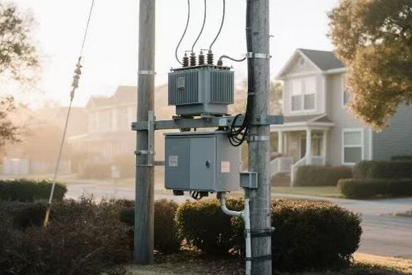
Steps to Calculate Peak and Average Load Requirements
Let’s break down the process of calculating load requirements:
1. Gather Historical Data
- Collect past electricity usage data
- Analyze at least 12 months of data for seasonal patterns
2. Conduct Load Surveys
- Measure actual power consumption of connected devices
- Use power logging devices for accurate readings
I once conducted a load survey for a small industrial park that revealed surprising results. The actual peak load was 30% lower than what the sum of all connected equipment suggested, highlighting the importance of real-world measurements.
3. Determine Diversity Factor
- Calculate the ratio of the sum of individual maximum demands to the maximum demand on the system
- Diversity Factor = Sum of Individual Max Demands ÷ System Max Demand
4. Calculate Connected Load
- Sum up the nameplate ratings of all connected equipment
- Connected Load = Σ (Rated Power of Each Device)
5. Estimate Peak Load
- Apply diversity factor to connected load
- Peak Load = Connected Load × (1 ÷ Diversity Factor)
6. Calculate Average Load
- Typically 60-70% of peak load for residential areas
- Can vary significantly for commercial and industrial applications
Here’s a table showing typical diversity factors:
| Load Type | Typical Diversity Factor |
|---|---|
| Residential | 0.2 – 0.4 |
| Commercial | 0.5 – 0.7 |
| Industrial | 0.7 – 0.9 |
In my experience, one of the most common mistakes in load calculation is relying solely on connected load without considering diversity. I remember a project for a large office building where the initial calculations based on connected load suggested a 1000 kVA transformer. However, after a detailed load study and applying appropriate diversity factors, we determined that a 630 kVA transformer was more than sufficient.
Seasonal variations can significantly impact load calculations. In a resort area project, we found that the peak load during the tourist season was almost double the off-season load. We had to size the transformer to handle these seasonal peaks while remaining efficient during lower demand periods.
Future growth projection is crucial in load calculations. I always advise clients to consider a 5-10 year growth plan. In a rapidly developing commercial area, we added a 25% capacity buffer to our calculations, which proved invaluable as new businesses moved in over the next few years.
Power factor correction can greatly affect load calculations. In an industrial setting, implementing power factor correction allowed us to reduce the required transformer size by 15%, resulting in significant cost savings.
For areas with significant non-linear loads, such as data centers or industrial facilities with many variable frequency drives, harmonic analysis is essential. In one project, we had to oversize the transformer by 20% to account for harmonic heating effects, ensuring long-term reliability.
Load profiling is another valuable tool in accurate load calculation. By using data loggers to capture load variations over time, we can get a more precise picture of peak and average demands. In a mixed-use development project, this approach allowed us to optimize transformer sizing for different areas based on their unique load profiles.
It’s also important to consider the impact of energy efficiency initiatives on load calculations. In a recent retrofit project for a manufacturing facility, upgrading to more efficient equipment reduced the peak load by 25%, allowing for a smaller transformer during replacement.
Lastly, the increasing adoption of renewable energy sources and electric vehicles adds complexity to load calculations. In a recent residential development project, we had to factor in potential solar panel installations and EV charging stations. This required a more flexible approach to transformer sizing, allowing for bidirectional power flow and potential load growth.
By carefully considering all these factors and using a combination of historical data, real-world measurements, and predictive modeling, we can accurately calculate peak and average load requirements. This precision in load calculation is crucial for optimal transformer sizing, ensuring efficiency, reliability, and future-readiness in our power distribution systems.
Common Sizing Mistakes and How to Avoid Them?
Have you ever wondered why some power systems underperform or why energy costs sometimes skyrocket unexpectedly? Often, these issues can be traced back to common mistakes in transformer sizing. But what are these mistakes, and how can we avoid them?
Common transformer sizing mistakes include overreliance on nameplate ratings, ignoring load diversity, neglecting future growth, and overlooking environmental factors. To avoid these, use actual load data, consider diversity factors, plan for future expansion, and account for local conditions. Proper sizing ensures efficiency, reliability, and cost-effectiveness.
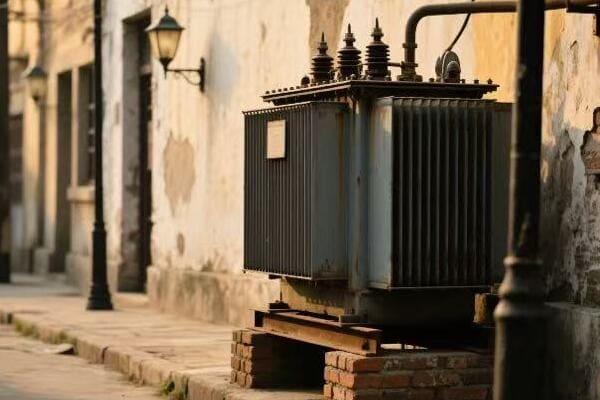
Identifying and Avoiding Common Sizing Mistakes
Let’s explore the most frequent sizing errors and how to prevent them:
1. Overreliance on Nameplate Ratings
Mistake:
- Summing up all connected load ratings without considering actual usage patterns
Solution:
- Conduct load surveys to determine actual power consumption
- Use data logging tools to capture real-world usage patterns
I once encountered a situation where a factory had installed a transformer based solely on the sum of all equipment ratings. This led to a significantly oversized and inefficient system. After conducting a detailed load study, we were able to downsize the transformer by 30%, improving efficiency and reducing costs.
2. Ignoring Load Diversity
Mistake:
- Assuming all loads operate at maximum capacity simultaneously
Solution:
- Apply appropriate diversity factors based on load type and usage patterns
- Use historical data to determine realistic peak loads
3. Neglecting Future Growth
Mistake:
- Sizing only for current needs without considering potential expansion
Solution:
- Factor in projected growth over the next 5-10 years
- Design for modularity to allow for future upgrades
4. Overlooking Environmental Factors
Mistake:
- Failing to account for local climate conditions and their impact on transformer performance
Solution:
- Consider ambient temperature, altitude, and humidity in sizing calculations
- Adjust sizing or specify additional cooling for harsh environments
Here’s a table summarizing these mistakes and their solutions:
| Common Mistake | Potential Consequence | Solution |
|---|---|---|
| Overreliance on Nameplate Ratings | Oversizing, inefficiency | Use actual load data |
| Ignoring Load Diversity | Oversizing, higher costs | Apply diversity factors |
| Neglecting Future Growth | Undersizing in long term | Plan for expansion |
| Overlooking Environmental Factors | Reduced performance, failures | Account for local conditions |
In my experience, one of the most overlooked aspects in transformer sizing is the impact of power quality issues. I recall a project in an industrial park where harmonics from variable frequency drives were causing excessive heating in the transformers. By failing to account for this, the initially installed transformers were undersized for the actual load. We had to retrofit harmonic filters and upgrade some transformers to resolve the issue.
Another common mistake is not considering the starting currents of large motors. In a water treatment plant project, the initial sizing didn’t account for the high inrush currents of pump motors. This led to voltage dips and potential nuisance tripping. We resolved this by slightly upsizing the transformer and implementing soft starters for the largest motors.
Seasonal load variations are often underestimated in sizing calculations. I worked on a project for a ski resort where the winter load was dramatically higher than the summer load. The challenge was to size a transformer that could handle peak winter demands while remaining efficient during low-load summer months. We ended up using a combination of a base load transformer and a smaller auxiliary unit that could be brought online during peak seasons.
The increasing integration of renewable energy sources presents new challenges in transformer sizing. In a recent microgrid project, we had to carefully size the transformer to handle both traditional loads and the variable input from solar panels. This required a more dynamic approach to sizing, considering bidirectional power flow and potential storage systems.
Energy efficiency initiatives can sometimes lead to sizing mistakes. In one case, a commercial building underwent extensive energy-efficient upgrades, significantly reducing its power demand. However, they failed to reassess their transformer sizing, leading to an oversized and inefficient system. It’s crucial to reevaluate transformer sizes after major efficiency improvements.
Lastly, the trend towards electrification, particularly with electric vehicles, is changing the landscape of transformer sizing. In a recent residential development project, we had to factor in potential EV charging loads. This required not just larger transformers but also more flexible designs to accommodate potential future load growth.
By being aware of these common mistakes and implementing the suggested solutions, we can ensure more accurate and efficient transformer sizing. This not only improves system performance and reliability but also optimizes costs and energy efficiency in the long run. Remember, proper sizing is not just about meeting current needs – it’s about creating a flexible, efficient, and future-proof power distribution system.
Power Pole Transformer Sizing Example (Case Study)?
Have you ever wondered how engineers determine the right size for a power pole transformer in a real-world scenario? Let’s walk through a practical example to illustrate the process. This case study will demonstrate how various factors come into play when sizing a transformer for a specific application.
This case study examines sizing a transformer for a new residential development. It considers factors like number of homes, average and peak load estimates, future growth, and local climate. The process involves load calculation, diversity factor application, and adjustment for environmental conditions to determine the optimal transformer size.
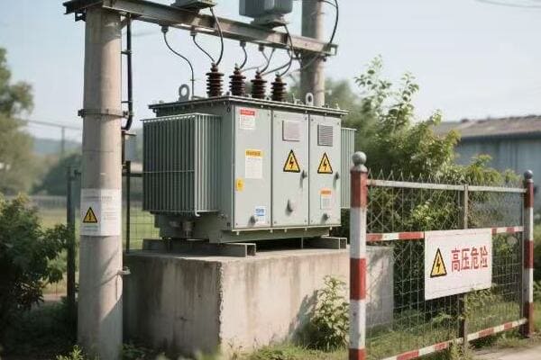
Case Study: Sizing a Transformer for a New Residential Development
Let’s go through the steps of sizing a transformer for a new neighborhood:
Scenario Details
- New development with 50 single-family homes
- Located in a suburban area with mild climate
- Future plans for 10 additional homes in 5 years
Step 1: Estimate Connected Load
- Average home size: 2,000 sq ft
- Estimated load per home: 7.5 kVA
- Total connected load: 50 homes × 7.5 kVA = 375 kVA
I remember a similar project where we initially overestimated the per-home load. After conducting surveys of comparable neighborhoods, we found that 7.5 kVA per home was a more realistic figure for this type of development.
Step 2: Apply Diversity Factor
- Typical diversity factor for residential areas: 0.3
- Peak demand estimate: 375 kVA × 0.3 = 112.5 kVA
Step 3: Consider Future Growth
- Additional 10 homes: 10 × 7.5 kVA × 0.3 = 22.5 kVA
- Total future peak demand: 112.5 kVA + 22.5 kVA = 135 kVA
Step 4: Account for Environmental Factors
- Mild climate: No significant derating required
- Add 10% capacity for safety margin
Step 5: Final Sizing Calculation
- Required capacity: 135 kVA × 1.1 = 148.5 kVA
- Select standard transformer size: 167 kVA
Here’s a summary table of our calculations:
| Calculation Step | Value |
|---|---|
| Total Connected Load | 375 kVA |
| Peak Demand (with diversity) | 112.5 kVA |
| Future Growth Allowance | 22.5 kVA |
| Subtotal | 135 kVA |
| Safety Margin (10%) | 13.5 kVA |
| Final Required Capacity | 148.5 kVA |
| Selected Transformer Size | 167 kVA |
In my experience, it’s crucial to validate these calculations with real-world data whenever possible. In a similar project, we installed temporary monitoring equipment in an existing comparable neighborhood. This gave us valuable insights into actual usage patterns, helping refine our estimates.
One factor we always consider is the potential for electric vehicle (EV) adoption. In this case study, we might want to add an additional allowance for EV charging. For instance, assuming 20% of homes might have EVs in the future, we could add:
10 EVs × 7.2 kW (Level 2 charger) × 0.5 (diversity factor for EV charging) = 36 kW additional capacity
This would bring our total required capacity to about 185 kVA, potentially pushing us to the next standard size of 250 kVA.
Another important consideration is the potential for renewable energy integration. If the development is likely to see significant solar panel installations, we might need to design for bidirectional power flow. This could affect our choice of transformer features, even if it doesn’t necessarily increase the kVA rating.
Load growth patterns can sometimes surprise us. In one similar project, we found that actual load growth exceeded projections due to increasing home office use and general electrification trends. It’s often wise to err on the side of caution when considering future capacity needs.
The impact of energy efficiency measures should also be considered. In some cases, aggressive energy efficiency standards in new construction have led to lower-than-expected loads. However, this is often balanced by increased electrification of heating and transportation.
Lastly, it’s important to consider the transformer’s efficiency at different load levels. In this case, the selected 167 kVA transformer will be operating at about 70-80% of its capacity under peak conditions, which is generally a good efficiency point for most transformers.
This case study demonstrates the complex interplay of factors in transformer sizing. By carefully considering current needs, future growth, environmental factors, and emerging trends, we can select a transformer size that will provide reliable, efficient service for years to come.
Tools and Standards to Use for Accurate Selection?
Are you feeling overwhelmed by the complexity of transformer sizing? You’re not alone. Many engineers struggle with this task, but fortunately, there are tools and standards available to help ensure accurate selection. But what are these resources, and how can you use them effectively?
Accurate transformer selection relies on tools like load calculation software, power system analysis programs, and thermal modeling tools. Key standards include IEEE C57.91 for loading guidance, ANSI C84.1 for voltage ratings, and NEC for installation requirements. These resources help engineers make informed decisions based on industry best practices.
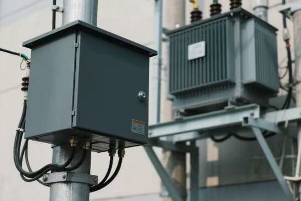
Essential Tools and Standards for Transformer Sizing
Let’s explore the key resources that can aid in accurate transformer selection:
Software Tools
-
Load Calculation Software:
- Examples: SKM Power Tools, ETAP
- Uses: Detailed load analysis and forecasting
-
Power System Analysis Programs:
- Examples: PowerWorld, DIgSILENT PowerFactory
- Uses: Simulate system behavior, voltage drop calculations
-
Thermal Modeling Tools:
- Examples: COMSOL Multiphysics, ANSYS
- Uses: Analyze transformer heating and cooling performance
I once used thermal modeling software to optimize the design of a transformer for a particularly hot climate. The insights gained allowed us to specify a more efficient cooling system, ensuring reliable operation in extreme conditions.
Key Standards and Guidelines
-
IEEE C57.91:
- Guide for Loading Mineral-Oil-Immersed Transformers
- Provides loading guidance and life expectancy calculations
-
ANSI C84.1:
- Electric Power Systems and Equipment – Voltage Ratings (60 Hz)
- Defines standard voltage ratings and tolerances
-
National Electrical Code (NEC):
- Article 450 covers transformer installation requirements
-
IEC 60076:
- Power Transformers – International standard for design and testing
Here’s a table summarizing these tools and standards:
| Resource Type | Examples | Primary Use |
|---|---|---|
| Load Calculation Software | SKM Power Tools, ETAP | Detailed load analysis |
| Power System Analysis | PowerWorld, DIgSILENT | System simulation |
| Thermal Modeling | COMSOL, ANSYS | Thermal performance analysis |
| Loading Standards | IEEE C57.91 | Loading guidance |
| Voltage Standards | ANSI C84.1 | Voltage ratings |
| Installation Codes | NEC Article 450 | Installation requirements |
In my experience, the effective use of these tools and standards can significantly improve the accuracy and reliability of transformer sizing decisions. I recall a project where we used a combination of load calculation software and power system analysis to optimize the sizing of transformers in a large industrial complex. This integrated approach allowed us to account for factors like motor starting currents and harmonic loads, resulting in a more robust and efficient system design.
One often overlooked aspect is the importance of accurate input data. Even the most sophisticated software tools are only as good as the data they’re fed. I always emphasize the need for thorough site surveys and historical load data analysis before inputting information into these tools.
The IEEE C57.91 standard has been particularly valuable in my work, especially when dealing with transformers in challenging environments. It provides crucial guidance on how various factors like ambient temperature and loading patterns affect transformer life expectancy. In one project, we used this standard to justify a slightly larger transformer size, which ultimately extended the expected life of the unit by several years.
For voltage considerations, ANSI C84.1 is indispensable. It helps ensure that the selected transformer can maintain voltage within acceptable limits under various loading conditions. This is especially critical in areas with long distribution lines or significant voltage fluctuations.
The National Electrical Code provides essential guidelines for safe transformer installation. However, it’s important to note that local codes may have additional requirements. I always advise checking with local authorities to ensure compliance with all relevant regulations.
In recent years, I’ve seen an increasing emphasis on energy efficiency in transformer selection. Tools that can model transformer losses under various loading conditions have become invaluable. These help in selecting units that not only meet current needs but also optimize long-term operating costs.
For projects involving renewable energy integration, specialized tools that can model bidirectional power flow and intermittent generation have become essential. These help in sizing transformers that can handle the unique challenges posed by solar and wind power systems.
Lastly, it’s worth mentioning the growing importance of lifecycle cost analysis tools. These help in balancing initial costs with long-term operational expenses, allowing for more informed decision-making in transformer selection.
By leveraging these tools and adhering to established standards, we can ensure more accurate, efficient, and reliable transformer sizing. Remember, while these resources are invaluable, they should complement, not replace, engineering judgment and experience. The best results come from a combination of advanced tools, industry standards, and seasoned expertise.
Conclusion
Proper power pole transformer sizing is crucial for efficient and reliable electrical distribution. It involves understanding load requirements, considering environmental factors, and using appropriate tools and standards. By avoiding common mistakes and following best practices, engineers can ensure optimal transformer performance, safety, and longevity in various applications.
Are you tired of unexpected power outages disrupting your daily life? These interruptions often stem from failures in power pole transformers. Understanding these failures can help us prevent them and ensure a more reliable power supply.
The top 5 common failures in power pole transformers are overheating, lightning damage, corrosion, overloading, and loose connections. These issues can be prevented through regular maintenance, proper sizing, surge protection, weatherproofing, and careful installation. Addressing these problems can significantly improve transformer reliability and longevity.
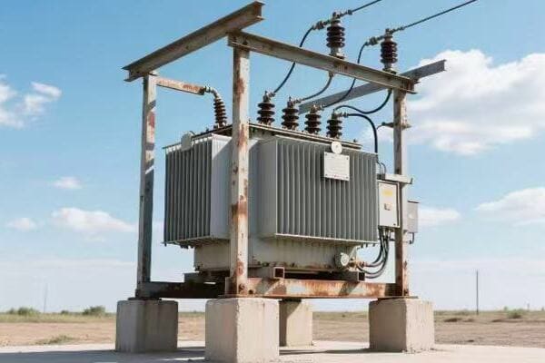
In this article, I’ll dive into each of these common failures, explaining their causes and how to prevent them. Whether you’re a field technician or just curious about power distribution, this guide will give you valuable insights into maintaining these crucial components of our electrical grid.
Introduction: Why Transformer Reliability Matters?
Have you ever considered how much we rely on a steady power supply? From charging our phones to running life-saving medical equipment, reliable electricity is crucial. At the heart of this reliability are power pole transformers, but what happens when they fail?
Transformer reliability is crucial for maintaining a stable power supply. Failures can lead to widespread outages, safety hazards, and significant economic losses. Ensuring transformer reliability through proper maintenance and design is essential for a resilient and efficient electrical grid.
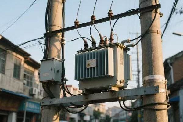
The Importance of Transformer Reliability
Let’s break down why transformer reliability is so critical:
1. Continuous Power Supply
Reliable transformers ensure a steady flow of electricity to homes and businesses. This is essential for:
- Maintaining daily activities
- Supporting critical infrastructure like hospitals and emergency services
- Keeping businesses operational
2. Safety Considerations
Transformer failures can pose serious safety risks:
- Risk of electrical fires
- Potential for electrocution
- Hazards from falling equipment
3. Economic Impact
Unreliable transformers can have significant economic consequences:
- Business interruptions leading to lost revenue
- Costs associated with emergency repairs
- Damage to electrical equipment in homes and businesses
I once worked on a project where a single transformer failure in an industrial area led to a day-long power outage. The economic impact was staggering – millions of dollars in lost production and spoiled goods. This experience really drove home the importance of transformer reliability.
4. Grid Stability
Transformers play a crucial role in maintaining overall grid stability:
- They help balance load distribution
- They’re key in voltage regulation
- Failures can lead to cascading outages
Here’s a table showing the potential impact of transformer failures:
| Impact Area | Short-Term Effects | Long-Term Consequences |
|---|---|---|
| Residential | Power outages, inconvenience | Damaged appliances, safety risks |
| Commercial | Business interruptions, data loss | Revenue loss, customer dissatisfaction |
| Industrial | Production halts, equipment damage | Economic losses, supply chain disruptions |
| Public Services | Emergency response delays | Reduced public trust, safety concerns |
Understanding these impacts helps us appreciate the critical nature of transformer reliability. In my years of experience in the power industry, I’ve seen how investing in reliable transformers and proper maintenance can save utilities and communities from significant problems down the line.
As we move towards more complex and interconnected power grids, especially with the integration of renewable energy sources, the role of reliable transformers becomes even more crucial. They’re not just passive components but active players in ensuring a stable and efficient power supply.
In the following sections, we’ll explore the most common failures that affect power pole transformers and discuss strategies to prevent them. By addressing these issues proactively, we can significantly enhance the reliability of our power distribution systems and minimize the impacts of transformer failures.
Failure #1: Overheating and Insulation Breakdown?
Have you ever touched an electronic device that felt too hot? Now imagine that heat in a massive transformer. Overheating is one of the most common and serious issues facing power pole transformers. But what causes it, and how can we prevent it?
Overheating in transformers often leads to insulation breakdown, causing short circuits and failures. It’s typically caused by overloading, poor cooling, or internal faults. Prevention involves proper load management, regular oil and cooling system maintenance, and using temperature monitoring devices.
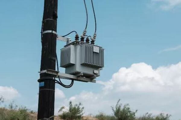
Understanding Overheating and Insulation Breakdown
Let’s dive deeper into this critical issue:
Causes of Overheating
-
Overloading:
- Exceeding the transformer’s rated capacity
- Sudden spikes in power demand
-
Cooling System Failures:
- Clogged radiators
- Low oil levels
- Malfunctioning cooling fans
-
Internal Faults:
- Short circuits in windings
- Deterioration of insulating materials
I once encountered a transformer that was consistently running hot. Upon investigation, we found that recent development in the area had increased power demand beyond the transformer’s capacity. This overloading was causing significant heat stress.
Effects of Overheating
Overheating can have severe consequences:
-
Insulation Breakdown:
- Degradation of oil and paper insulation
- Reduced dielectric strength
-
Accelerated Aging:
- Each 10°C increase above rated temperature can halve the transformer’s life
-
Increased Losses:
- Higher temperatures increase electrical resistance, leading to more energy loss
Prevention Strategies
Here are key strategies to prevent overheating:
-
Load Management:
- Regular load surveys
- Upgrading transformers in growing areas
-
Cooling System Maintenance:
- Regular oil testing and replacement
- Cleaning of cooling fins and radiators
-
Temperature Monitoring:
- Installing temperature sensors
- Using thermal imaging for regular checks
-
Improved Insulation:
- Using high-temperature insulation materials
- Implementing more efficient cooling designs
Here’s a table summarizing the impact of temperature on transformer lifespan:
| Operating Temperature | Expected Lifespan |
|---|---|
| Rated Temperature | 20-30 years |
| 10°C above rated | 10-15 years |
| 20°C above rated | 5-7 years |
| 30°C above rated | 2-3 years |
In my experience, implementing a comprehensive temperature monitoring system can make a huge difference. In one project, we installed smart sensors that provided real-time temperature data. This allowed the utility to detect and address heating issues before they led to failures, significantly improving reliability.
Another effective approach I’ve used is the implementation of dynamic loading. This involves adjusting the transformer’s load based on real-time temperature and ambient conditions. It allows for higher capacity utilization during cooler periods while preventing overheating during hot weather or peak demand times.
It’s also worth noting the importance of proper initial sizing. I’ve seen cases where transformers were undersized for growing communities, leading to chronic overheating issues. Proper planning and regular reassessment of load requirements are crucial for preventing these problems.
Lastly, don’t underestimate the impact of environmental factors. In areas with high ambient temperatures, additional cooling measures may be necessary. I once worked on a project in a desert region where we had to design custom cooling systems to handle the extreme heat.
By addressing overheating proactively, we can significantly extend the life of power pole transformers and improve the overall reliability of our power distribution systems. Remember, a cool transformer is a happy transformer!
Failure #2: Lightning or Surge Damage?
Have you ever wondered what happens when lightning strikes near a power line? Lightning and electrical surges pose a significant threat to power pole transformers. But how exactly do they cause damage, and what can we do to protect against them?
Lightning or surge damage can cause catastrophic failure in transformers through insulation breakdown and winding damage. It often results from direct lightning strikes or induced voltage surges. Prevention involves installing surge arresters, improving grounding systems, and using shielding techniques.
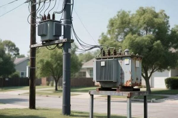
Understanding Lightning and Surge Damage
Let’s explore this electrifying topic in more detail:
How Lightning Affects Transformers
-
Direct Strikes:
- Can cause immediate, catastrophic damage
- May lead to explosive failure of the transformer
-
Induced Surges:
- Lightning strikes nearby can induce high voltages in power lines
- These surges can travel to the transformer, causing internal damage
-
Secondary Effects:
- Damage to control and monitoring systems
- Degradation of insulation materials
I once investigated a transformer failure that occurred during a severe thunderstorm. The damage was extensive, with clear signs of a lightning-induced surge. It was a stark reminder of nature’s power and the importance of proper protection.
Types of Surge Damage
Surges can cause various types of damage:
-
Insulation Breakdown:
- High voltages can puncture or degrade insulation materials
-
Winding Damage:
- Surges can cause short circuits between winding turns
-
Bushing Failures:
- High-voltage surges can crack or damage bushings
-
Oil Degradation:
- Electrical arcing in the oil can lead to its breakdown
Prevention and Protection Strategies
Here are key strategies to protect against lightning and surge damage:
-
Surge Arresters:
- Installing arresters on transformer terminals
- Regular testing and replacement of arresters
-
Improved Grounding:
- Ensuring low-impedance grounding systems
- Regular ground resistance testing
-
Shielding:
- Using overhead ground wires for lightning protection
- Shielding sensitive control wires
-
Insulation Coordination:
- Proper selection of insulation levels for equipment
Here’s a table comparing different surge protection methods:
| Protection Method | Effectiveness | Cost | Maintenance Needs |
|---|---|---|---|
| Surge Arresters | High | Moderate | Regular testing |
| Improved Grounding | Very High | High | Periodic checks |
| Overhead Shield Wires | High | High | Low |
| Insulation Coordination | Moderate | Low | Design phase only |
In my experience, a multi-layered approach to surge protection is most effective. I recall a project where we implemented a combination of high-quality surge arresters and an enhanced grounding system. During the next storm season, we saw a significant reduction in surge-related transformer failures.
It’s also important to consider the geographical location when designing surge protection. In areas with high lightning activity, more robust protection measures are necessary. I once worked in a region known for its frequent thunderstorms. We had to design a custom lightning protection system that included additional arresters and a more extensive grounding network.
Another aspect often overlooked is the protection of control and monitoring systems. These low-voltage circuits can be particularly vulnerable to surge damage. Implementing separate surge protection for these systems can prevent costly failures and improve overall reliability.
Regular maintenance and testing of surge protection devices are crucial. I’ve seen cases where old or faulty surge arresters actually contributed to transformer failures instead of preventing them. Establishing a routine inspection and replacement schedule is essential for ensuring continued protection.
Lastly, it’s worth mentioning the importance of rapid response to lightning strikes. Even with the best protection, some damage may occur. Having a plan for quick assessment and necessary repairs after a lightning event can minimize downtime and prevent small issues from escalating into major failures.
By implementing comprehensive surge protection strategies, we can significantly reduce the risk of lightning and surge damage to power pole transformers. This not only extends the life of these critical components but also ensures a more reliable and resilient power distribution system.
Failure #3: Corrosion and Weather Exposure?
Have you ever noticed how metal objects left outside start to rust over time? Now imagine this happening to a crucial piece of electrical equipment like a power pole transformer. Corrosion and weather exposure are silent but persistent threats to transformer reliability. But what exactly causes this damage, and how can we protect against it?
Corrosion and weather exposure can severely damage transformer components, leading to leaks, structural weakness, and electrical faults. These issues are often caused by moisture, pollutants, and extreme temperatures. Prevention involves using corrosion-resistant materials, applying protective coatings, and implementing regular inspection and maintenance routines.
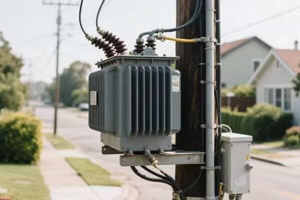
Understanding Corrosion and Weather Exposure
Let’s delve into the details of this pervasive problem:
Causes of Corrosion and Weather Damage
-
Moisture Exposure:
- Rain, snow, and high humidity
- Condensation inside the transformer
-
Atmospheric Pollutants:
- Salt in coastal areas
- Industrial pollutants in urban environments
-
Temperature Fluctuations:
- Expansion and contraction of materials
- Accelerated chemical reactions in high temperatures
-
UV Radiation:
- Degradation of external coatings and insulation
I once inspected a transformer in a coastal area that showed severe corrosion after just a few years of service. The salt-laden air had accelerated the corrosion process, highlighting the need for specialized protection in such environments.
Effects of Corrosion and Weather Exposure
Corrosion and weather can cause various issues:
-
Tank Integrity:
- Rust and pitting leading to oil leaks
- Structural weakening of the transformer tank
-
Electrical Connections:
- Corrosion of terminals and bushings
- Increased contact resistance leading to heating
-
Insulation Degradation:
- Breakdown of paper and oil insulation
- Reduced dielectric strength
-
Cooling System Efficiency:
- Clogging of radiator fins
- Reduced heat dissipation capacity
Prevention and Protection Strategies
Here are key strategies to protect against corrosion and weather damage:
-
Material Selection:
- Using corrosion-resistant alloys for tank construction
- Selecting weather-resistant gaskets and seals
-
Protective Coatings:
- Applying high-quality, weather-resistant paints
- Using galvanization for exposed metal parts
-
Design Considerations:
- Implementing sealed designs to minimize moisture ingress
- Proper drainage and ventilation to prevent water accumulation
-
Regular Maintenance:
- Scheduled inspections for signs of corrosion
- Prompt repair of any damaged coatings or seals
Here’s a table comparing different corrosion protection methods:
| Protection Method | Effectiveness | Longevity | Cost |
|---|---|---|---|
| Stainless Steel Construction | Very High | 20+ years | High |
| Galvanization | High | 10-15 years | Moderate |
| Epoxy Coating | High | 5-10 years | Low to Moderate |
| Regular Painting | Moderate | 2-5 years | Low |
In my experience, a combination of these methods often provides the best protection. I recall a project where we used a stainless steel tank with additional epoxy coating for transformers in a highly corrosive industrial environment. The extra cost was justified by the significantly extended service life and reduced maintenance needs.
It’s also crucial to consider the specific environmental challenges of each location. In one coastal project, we implemented a custom maintenance schedule that included more frequent inspections and reapplication of protective coatings. This proactive approach helped prevent corrosion-related failures and extended the transformers’ lifespan.
Another often overlooked aspect is the importance of proper installation. Ensuring that transformers are mounted at the correct height, with proper drainage and ventilation, can significantly reduce moisture-related issues. I’ve seen cases where simple adjustments in installation practices led to notable improvements in corrosion resistance.
Advancements in materials science have also opened up new possibilities for corrosion protection. In recent years, I’ve been experimenting with nano-coatings that provide exceptional corrosion resistance. While still relatively expensive, these cutting-edge solutions show promise for extreme environments.
Lastly, it’s worth mentioning the role of environmental monitoring. Implementing systems to track humidity, temperature, and air quality can help predict and prevent corrosion issues before they become severe. In one project, we installed smart sensors that alerted maintenance teams to conditions conducive to corrosion, allowing for timely interventions.
By implementing comprehensive corrosion and weather protection strategies, we can significantly extend the life of power pole transformers and reduce maintenance costs. This not only improves the reliability of our power distribution systems but also contributes to more sustainable and cost-effective infrastructure management.
Failure #4: Overloading from Improper Sizing?
Have you ever tried to power too many appliances from a single outlet? Now imagine this scenario on a much larger scale with a power pole transformer. Overloading due to improper sizing is a common yet often overlooked issue that can lead to premature transformer failure. But why does it happen, and how can we prevent it?
Overloading from improper sizing occurs when a transformer consistently operates above its rated capacity. This can lead to overheating, insulation breakdown, and reduced lifespan. Prevention involves accurate load forecasting, proper initial sizing, regular load monitoring, and timely upgrades when necessary.
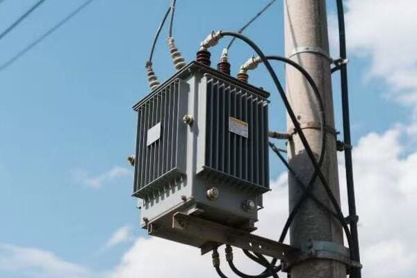
Understanding Overloading from Improper Sizing
Let’s explore this issue in more detail:
Causes of Overloading
-
Underestimating Future Growth:
- Failing to account for population increase in an area
- Not considering new developments or industrial expansions
-
Changing Usage Patterns:
- Increased adoption of high-power devices (e.g., electric vehicles)
- Shifts in energy consumption habits
-
Inadequate Planning:
- Using outdated load calculation methods
- Neglecting to reassess transformer capacity periodically
I once encountered a situation in a rapidly growing suburban area where the original transformer sizing didn’t account for the surge in electric vehicle adoption. Within a few years, the transformer was consistently overloaded during evening charging hours.
Effects of Overloading
Overloading can have serious consequences:
-
Accelerated Aging:
- Insulation degradation due to excessive heat
- Reduced transformer lifespan
-
Increased Losses:
- Higher copper and core losses
- Reduced energy efficiency
-
Risk of Catastrophic Failure:
- Potential for oil breakdown and internal arcing
- Increased risk of transformer explosion
-
Power Quality Issues:
- Voltage drops during peak load times
- Potential for wider grid instability
Prevention Strategies
Here are key strategies to prevent overloading:
-
Accurate Load Forecasting:
- Using advanced modeling techniques
- Considering demographic trends and development plans
-
Conservative Initial Sizing:
- Choosing transformers with some extra capacity for future growth
- Implementing modular designs for easy upgrades
-
Regular Load Monitoring:
- Installing smart meters for real-time load data
- Conducting periodic load surveys
-
Timely Upgrades:
- Establishing clear thresholds for transformer replacement
- Planning for upgrades before critical overload situations occur
Here’s a table showing the impact of overloading on transformer lifespan:
| Overload Percentage | Continuous Operation Time | Expected Lifespan Reduction |
|---|---|---|
| 10% | 24 hours | 50% |
| 20% | 2 hours | 25% |
| 30% | 1 hour | 40% |
| 50% | 5 minutes | Potential immediate failure |
In my experience, implementing a comprehensive load management system can make a significant difference. In one project, we installed smart monitoring devices on all transformers in a district. This allowed us to track load patterns in real-time and identify potential overload situations before they became critical.
Another effective approach I’ve used is the concept of "staged capacity." This involves installing a transformer base that can accommodate larger units, even if the initial load doesn’t require it. As the load grows, the transformer can be easily upgraded without needing to replace the entire installation.
It’s also crucial to consider the impact of distributed energy resources, such as rooftop solar panels. In one community, we had to redesign the transformer sizing strategy to account for bidirectional power flow and intermittent generation. This required a more sophisticated approach to load calculation and transformer selection.
Regular communication with local planning departments and developers is essential. I’ve found that staying informed about upcoming developments and changes in zoning can provide valuable insights for future load growth. This proactive approach has helped utilities stay ahead of capacity needs.
Lastly, it’s worth mentioning the importance of educating consumers about energy efficiency and load management. In one project, we implemented a community outreach program to encourage off-peak usage of high-power appliances. This helped flatten the load curve and reduced the strain on transformers during peak hours.
By addressing the issue of proper sizing and load management, we can significantly extend the life of power pole transformers and improve the overall reliability of our power distribution systems. Remember, a well-sized transformer is a long-lasting transformer!
Failure #5: Loose Connections or Poor Installation?
Have you ever had a flickering light due to a loose bulb? Now imagine this on a much larger scale with a power pole transformer. Loose connections or poor installation might seem like minor issues, but they can lead to major problems in transformer performance and longevity. How do these issues arise, and what can we do to prevent them?
Loose connections or poor installation in transformers can cause overheating, arcing, and eventual failure. These issues often result from improper initial setup, vibration over time, or inadequate maintenance. Prevention involves proper installation techniques, regular inspections, thermal imaging, and timely tightening of connections.
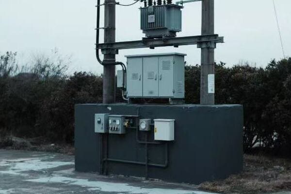
Understanding Loose Connections and Poor Installation
Let’s delve into the details of this often-overlooked issue:
Causes of Loose Connections and Poor Installation
-
Initial Installation Errors:
- Improper torque application
- Misalignment of components
-
Environmental Factors:
- Thermal cycling causing expansion and contraction
- Vibration from nearby equipment or wind
-
Material Degradation:
- Corrosion of connectors
- Aging of gaskets and seals
-
Inadequate Maintenance:
- Failure to perform regular inspections
- Neglecting to retighten connections periodically
I once investigated a transformer failure that was traced back to a single loose bushing connection. Over time, this minor issue led to arcing, which eventually caused a catastrophic failure. It was a stark reminder of how small oversights can have big consequences.
Effects of Loose Connections and Poor Installation
These issues can lead to various problems:
-
Increased Resistance:
- Generation of excess heat at connection points
- Higher energy losses
-
Arcing and Sparking:
- Damage to surrounding components
- Risk of fire or explosion
-
Oil Leaks:
- Loss of insulating oil
- Environmental contamination
-
Reduced Efficiency:
- Increased power losses
- Potential for voltage fluctuations
Prevention Strategies
Here are key strategies to prevent issues related to loose connections and poor installation:
-
Proper Installation Procedures:
- Using calibrated torque tools
- Following manufacturer guidelines strictly
-
Regular Inspections:
- Visual checks for signs of overheating or damage
- Thermal imaging to detect hot spots
-
Vibration Mitigation:
- Installing vibration dampeners
- Ensuring proper mounting and support
-
Maintenance Schedule:
- Regular retightening of connections
- Replacing worn gaskets and seals
Here’s a table showing the importance of proper torque in connections:
| Connection Type | Proper Torque Range | Consequences of Improper Torque |
|---|---|---|
| Bushing Terminals | 40-50 Nm | Overheating, arcing |
| Tank Bolts | 60-70 Nm | Oil leaks, structural issues |
| Tap Changer Contacts | 30-40 Nm | Poor voltage regulation |
| Ground Connections | 20-30 Nm | Increased safety risks |
In my experience, implementing a comprehensive installation and maintenance protocol can significantly reduce these issues. In one large-scale project, we developed a detailed checklist for installers and maintenance teams. This standardized approach led to a noticeable decrease in connection-related problems across the entire transformer fleet.
Another effective technique I’ve used is the application of anti-vibration compounds on critical connections. In areas prone to high winds or seismic activity, these compounds help maintain tight connections even under challenging conditions.
It’s also crucial to consider the impact of thermal cycling. In regions with extreme temperature variations, we’ve implemented special connection designs that allow for thermal expansion without loosening. This approach has proven particularly effective in preventing seasonal connection issues.
Training and certification of installation and maintenance personnel is another key factor. I’ve found that investing in regular training sessions and skill assessments for technicians pays off in terms of improved installation quality and reduced failure rates.
Lastly, the use of advanced monitoring technologies can play a crucial role. In recent projects, we’ve implemented smart sensors that continuously monitor connection integrity. These systems can detect early signs of loosening or overheating, allowing for proactive maintenance before serious issues develop.
By addressing the challenges of loose connections and poor installation, we can significantly enhance the reliability and longevity of power pole transformers. Remember, in the world of electrical connections, tight is right!
Preventive Maintenance Tips for Field Technicians?
Are you a field technician looking to improve your transformer maintenance skills? Or perhaps you’re a utility manager wondering how to keep your transformers in top shape? Effective preventive maintenance is key to extending the life of power pole transformers and ensuring reliable power distribution. But what are the best practices for maintaining these crucial components?
Preventive maintenance for power pole transformers involves regular inspections, oil testing, thermal imaging, and timely repairs. Key practices include checking for oil leaks, monitoring insulation resistance, inspecting bushings and connections, and keeping detailed maintenance records. Proper maintenance can significantly extend transformer life and prevent unexpected failures.
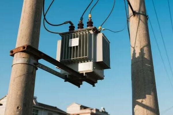
Essential Preventive Maintenance Tips
Let’s explore some crucial maintenance practices for field technicians:
1. Regular Visual Inspections
- Check for oil leaks around seals and gaskets
- Inspect bushings for cracks or contamination
- Look for signs of rust or physical damage
- Ensure proper oil levels in sight glasses
I once caught a small oil leak during a routine inspection that could have led to a major failure if left unchecked. Never underestimate the power of a thorough visual inspection!
2. Oil Testing and Analysis
- Perform regular dissolved gas analysis (DGA)
- Check oil dielectric strength
- Monitor moisture content in oil
- Test for acidity and interfacial tension
3. Thermal Imaging
- Use infrared cameras to detect hot spots
- Focus on connections, bushings, and radiators
- Compare temperatures to baseline readings
- Document and trend temperature changes over time
4. Electrical Testing
- Measure insulation resistance
- Perform turns ratio tests
- Check winding resistance
- Conduct power factor tests on bushings
5. Mechanical Maintenance
- Tighten loose connections
- Clean cooling fins and radiators
- Lubricate moving parts (e.g., tap changers)
- Check and adjust oil levels
Here’s a table outlining a basic maintenance schedule:
| Maintenance Task | Frequency | Importance |
|---|---|---|
| Visual Inspection | Monthly | High |
| Oil Sampling | Annually | Critical |
| Thermal Imaging | Quarterly | High |
| Electrical Testing | Every 3-5 years | Critical |
| Connection Tightening | Annually | High |
In my experience, consistency in maintenance is key. I recall a utility that implemented a rigorous monthly inspection program. Within a year, they saw a 30% reduction in unexpected transformer failures.
Another crucial aspect is proper documentation. I always emphasize the importance of keeping detailed maintenance records. These records can reveal trends and help predict potential issues before they become critical.
One often overlooked area is the maintenance of auxiliary equipment. Things like cooling fans, pressure relief devices, and temperature gauges are crucial for proper transformer operation. I make it a point to include these in every maintenance routine.
Training is also vital. I’ve found that regular refresher courses for technicians on the latest maintenance techniques and safety procedures can significantly improve the quality of maintenance work.
Lastly, don’t underestimate the value of cleanliness. Keeping transformers and their surroundings clean can prevent many issues. I once saw a case where leaf litter accumulation led to overheating by blocking cooling fins. A simple cleaning routine could have prevented this.
Remember, good maintenance is not just about fixing problems – it’s about preventing them. By following these tips and staying vigilant, field technicians can play a crucial role in ensuring the reliability of our power distribution systems.
When to Repair vs Replace: Cost-Benefit Analysis?
Have you ever faced the tough decision of whether to repair an old appliance or buy a new one? Now imagine making that decision for a piece of equipment that costs hundreds of thousands of dollars and powers entire neighborhoods. This is the dilemma utilities often face with aging power pole transformers. But how do you decide when to repair and when to replace?
The decision to repair or replace a transformer depends on factors like age, condition, repair costs, and expected lifespan post-repair. Generally, repairs are favored for newer units with minor issues, while replacement is often more cost-effective for older transformers or those with major damage. A thorough cost-benefit analysis is crucial for making this decision.
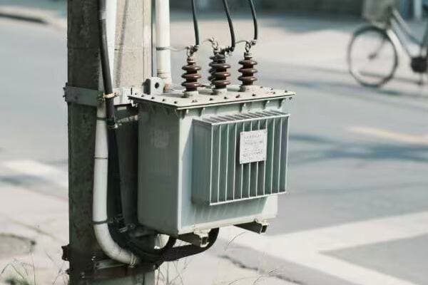
Analyzing the Repair vs Replace Decision
Let’s break down the key considerations in this critical decision-making process:
Factors to Consider
-
Age of the Transformer:
- Typical lifespan of 20-30 years
- Older units may have outdated technology
-
Extent of Damage:
- Minor issues vs. major failures
- Availability of replacement parts
-
Cost Comparison:
- Repair costs vs. new transformer price
- Consider future maintenance needs
-
Performance and Efficiency:
- Energy efficiency of old vs. new units
- Potential for improved features in new models
-
Regulatory Compliance:
- Changes in environmental or safety regulations
- Compatibility with smart grid technologies
I once worked with a utility facing a decision on a 25-year-old transformer with a minor oil leak. While the repair seemed simple, our analysis showed that replacing it with a more efficient model would pay off within five years due to reduced losses.
Cost-Benefit Analysis
Here’s a simplified approach to cost-benefit analysis:
-
Calculate Total Cost of Repair:
- Immediate repair costs
- Estimated future maintenance
- Projected efficiency losses
-
Estimate Replacement Costs:
- Purchase price of new transformer
- Installation and commissioning costs
- Disposal costs of old unit
-
Compare Long-term Benefits:
- Energy savings from improved efficiency
- Reduced maintenance needs
- Increased reliability
-
Consider Non-financial Factors:
- Environmental impact
- Improved safety features
- Enhanced monitoring capabilities
Here’s a table to help visualize the comparison:
| Factor | Repair | Replace |
|---|---|---|
| Upfront Cost | Lower | Higher |
| Long-term Efficiency | Lower | Higher |
| Expected Lifespan | 5-10 years | 20-30 years |
| Maintenance Needs | Higher | Lower |
| Compatibility with New Tech | Limited | Full |
In my experience, the decision often comes down to more than just numbers. I recall a case where a utility chose to replace a transformer that could have been repaired because the new unit offered advanced monitoring capabilities that aligned with their smart grid initiatives.
It’s also important to consider the broader context. In one project, we decided to repair several transformers in a rural area because the lead time for new units was too long, and maintaining power reliability was crucial for the community.
Another factor to consider is the potential for upgrades. Sometimes, repairing an old transformer can be combined with upgrades that improve its performance. I’ve seen cases where adding modern cooling systems or upgrading insulation materials gave old transformers a new lease on life.
The environmental impact is becoming an increasingly important consideration. In recent years, I’ve been involved in projects where the decision to replace was influenced by the opportunity to switch to more environmentally friendly insulating fluids.
Lastly, it’s crucial to have a standardized decision-making process. I often recommend utilities develop a scoring system that weighs various factors like age, condition, efficiency, and strategic importance. This helps ensure consistent and objective decision-making across their transformer fleet.
Remember, the goal is to balance short-term costs with long-term benefits. While repairing might seem cheaper initially, replacing with a more efficient and reliable unit often proves more economical in the long run. Each situation is unique, and a thorough analysis is key to making the right choice.
Conclusion
Understanding and addressing the top 5 common failures in power pole transformers is crucial for maintaining a reliable electrical grid. Through proper maintenance, timely repairs, and strategic replacements, we can significantly extend transformer life and prevent unexpected outages. Regular inspections and proactive measures are key to ensuring long-term reliability and efficiency.
Have you ever noticed the differences in power distribution between cities and countryside areas? The way electricity reaches our homes can vary greatly depending on where we live. This difference is largely due to how power pole transformers operate in these diverse environments.
Power pole transformers work similarly in rural and urban grids, stepping down high voltage to usable levels. However, they face different challenges in each setting. Urban transformers deal with higher load densities and space constraints, while rural ones must handle longer distances and more varied terrain.
In this article, I’ll explore how power pole transformers function in both rural and urban environments. We’ll look at their basic operation, the unique challenges they face in each setting, and how these differences impact our power supply. Let’s dive into the world of power distribution and see how these crucial devices adapt to their surroundings.
What Is a Power Pole Transformer and What Does It Do?
Have you ever looked up at those cylindrical objects on power poles and wondered what they are? These devices, called power pole transformers, play a crucial role in delivering electricity to our homes and businesses. But what exactly do they do?
A power pole transformer is a device that changes the voltage of electricity in power lines. It steps down high voltage from transmission lines to lower, safer levels for use in homes and businesses. This process is key to efficient power distribution across long distances and safe use in local areas.

Understanding Power Pole Transformers
Let’s break down the key aspects of power pole transformers:
Basic Function
Power pole transformers have one main job: to change voltage levels. They take high-voltage electricity from main power lines and reduce it to a level that’s safe for use in our homes and businesses. This process is called "stepping down" the voltage.
Key Components
- Core: Made of laminated steel sheets
- Windings: Two sets of coiled wires (primary and secondary)
- Insulating Oil: For cooling and insulation
- Tank: Houses all components
- Bushings: Allow electrical connections in and out
How They Work
The transformer uses a principle called electromagnetic induction. Here’s a simple breakdown:
- High voltage electricity enters the primary winding
- This creates a changing magnetic field in the core
- The magnetic field induces a lower voltage in the secondary winding
- The lower voltage electricity exits for distribution
I remember explaining this concept to a group of students once. I used a simple analogy: imagine the transformer as a gear system in a bike. Just as gears can change the speed and force of pedaling, transformers change the "force" (voltage) of electricity.
Importance in Power Distribution
Power pole transformers are crucial for several reasons:
- Efficiency: They allow power to be transmitted at high voltages over long distances, which reduces energy losses.
- Safety: They step down voltage to safe levels for home use.
- Flexibility: They can be adjusted to meet varying local power needs.
Here’s a table showing typical voltage levels in power distribution:
| Stage | Voltage Level |
|---|---|
| Power Plant Generation | 10,000 – 25,000 V |
| Long Distance Transmission | 155,000 – 765,000 V |
| Sub-transmission | 69,000 – 138,000 V |
| Distribution | 4,000 – 34,500 V |
| Home/Business Use | 120/240 V |
In my experience, the role of power pole transformers is often underappreciated. I once worked on a project to upgrade transformers in an older neighborhood. The residents were experiencing frequent power fluctuations. After installing new, more efficient transformers, the power quality improved dramatically. The residents were amazed at the difference, not realizing how crucial these devices are to their daily lives.
Power pole transformers are the unsung heroes of our electrical grid. They work silently, day and night, ensuring that we have safe, reliable power in our homes and businesses. As we continue to rely more heavily on electricity in our daily lives, the importance of these devices only grows. Understanding their function helps us appreciate the complex infrastructure that powers our modern world.
Key Differences Between Rural and Urban Power Distribution Systems?
Have you ever wondered why power outages seem more common in rural areas compared to cities? Or why the power infrastructure looks different in these two settings? The answer lies in the unique characteristics of rural and urban power distribution systems.
Rural and urban power distribution systems differ in load density, distance covered, and infrastructure design. Urban systems handle higher loads in smaller areas, using more transformers. Rural systems cover larger areas with lower population density, requiring fewer but more spread-out transformers.
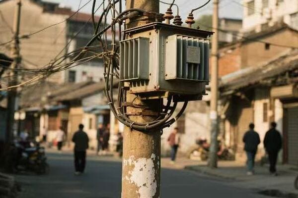
Comparing Rural and Urban Power Distribution
Let’s explore the key differences between rural and urban power distribution systems:
Load Density and Demand
-
Urban Areas:
- Higher population density
- More concentrated power demand
- Greater number of commercial and industrial consumers
-
Rural Areas:
- Lower population density
- Spread out power demand
- Mostly residential and agricultural consumers
In my experience, this difference in load density is one of the biggest challenges in power distribution. I once worked on a project to upgrade the power grid in a rapidly growing suburban area. We had to completely redesign the transformer layout to handle the increasing load density as the area transitioned from rural to urban.
Infrastructure Design
-
Urban Systems:
- More complex grid structure
- Higher number of substations and transformers
- Underground distribution common in some areas
-
Rural Systems:
- Simpler, more linear grid structure
- Fewer substations, transformers cover larger areas
- Mostly overhead distribution lines
Distance and Line Length
-
Urban Systems:
- Shorter distribution lines
- Lower line losses
- Easier maintenance and quicker repair times
-
Rural Systems:
- Longer distribution lines
- Higher line losses
- More challenging maintenance and longer repair times
I remember a particularly challenging project in a remote rural area. We had to design a system that could maintain voltage quality over long distances. It required careful placement of transformers and voltage regulators to ensure stable power delivery to the farthest points.
Reliability and Outages
-
Urban Systems:
- Generally more reliable due to redundancy
- Faster outage response times
- Less exposed to weather-related issues
-
Rural Systems:
- More vulnerable to outages
- Longer response times for repairs
- More exposed to weather and wildlife-related issues
Here’s a comparison table of key aspects:
| Aspect | Urban Distribution | Rural Distribution |
|---|---|---|
| Load Density | High | Low |
| Infrastructure Complexity | High | Low |
| Line Length | Short | Long |
| Number of Transformers | Many | Few |
| Outage Frequency | Lower | Higher |
| Maintenance Ease | Easier | More Challenging |
The differences between rural and urban power distribution systems significantly impact how we design and maintain these networks. In urban areas, the focus is often on managing high loads and ensuring reliability in a compact space. In rural areas, the challenges revolve around covering vast distances efficiently and maintaining service quality in remote locations.
These differences also affect the role and design of power pole transformers. In urban areas, transformers are typically smaller and more numerous, handling the concentrated loads of city blocks. In rural areas, transformers are often larger and more spread out, designed to serve wider areas with lower population density.
Understanding these differences is crucial for effective power system planning and management. As our energy needs evolve, with increasing adoption of renewable energy and electric vehicles, both rural and urban systems will need to adapt. The key is to recognize the unique challenges of each environment and design solutions that ensure reliable, efficient power delivery for all consumers, regardless of their location.
How Pole-Mounted Transformers Adapt to Urban Environments?
Have you ever wondered how cities manage to provide stable power despite the high demand and limited space? The answer lies in how pole-mounted transformers are adapted for urban use. These devices face unique challenges in city environments, but clever engineering solutions help them meet urban power needs effectively.
In urban environments, pole-mounted transformers are designed to handle higher loads in compact spaces. They often feature enhanced cooling systems, smart monitoring capabilities, and are strategically placed to serve high-density areas. Urban transformers also need to be more resilient to vandalism and integrate with underground distribution systems.
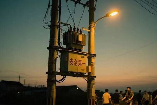
Adapting Transformers for Urban Use
Let’s explore how pole-mounted transformers are modified to suit urban environments:
Compact Design
Urban transformers often need to be smaller due to space constraints. This requires:
- More efficient cooling systems
- Use of advanced materials for better performance in smaller sizes
- Innovative designs to maximize power capacity in limited space
I once worked on a project in a densely populated urban area where space was at a premium. We had to design custom transformers that could fit in narrow alleyways while still meeting the high power demands of the neighborhood.
Enhanced Cooling Systems
Urban transformers often operate at higher loads, requiring better cooling:
- Use of more efficient cooling oils
- Addition of external cooling fins
- In some cases, forced-air cooling systems
Smart Monitoring and Control
Urban transformers increasingly incorporate smart technology:
- Real-time load monitoring
- Remote control capabilities
- Integration with smart grid systems for better load management
In a recent project, we installed smart transformers in a busy downtown area. These units could communicate with the utility’s control center, allowing for real-time load balancing and quick response to potential issues.
Vandalism Protection
Urban transformers are more exposed to potential vandalism:
- Reinforced enclosures
- Tamper-proof designs
- Installation at greater heights on poles
Integration with Underground Systems
Many urban areas use a combination of overhead and underground distribution:
- Transformers designed to connect easily to underground cables
- Pad-mounted designs for areas with fully underground distribution
Here’s a comparison of urban transformer features with standard rural designs:
| Feature | Urban Transformer | Standard Rural Transformer |
|---|---|---|
| Size | Compact | Larger |
| Cooling System | Enhanced | Basic |
| Smart Capabilities | Advanced | Limited or None |
| Vandalism Protection | High | Basic |
| Load Capacity | Higher | Lower |
| Underground Compatibility | Often Required | Rarely Needed |
The adaptation of pole-mounted transformers for urban use is a fascinating area of electrical engineering. In my experience, every urban project brings unique challenges. For instance, in one historic district, we had to design transformers that not only met the technical requirements but also blended with the architectural aesthetics of the area.
Another interesting aspect of urban transformer adaptation is noise reduction. In densely populated areas, the hum of transformers can be a nuisance. We’ve developed special vibration dampening systems and low-noise designs to address this issue.
The increasing adoption of electric vehicles in cities presents new challenges for urban transformers. In a recent project, we had to upgrade several transformers to handle the increased load from EV charging stations. This required not just higher capacity units, but also smarter load management systems to handle the variable demand.
Urban transformers also play a crucial role in power quality management. With the high concentration of sensitive electronic equipment in cities, maintaining stable voltage and minimizing harmonics is crucial. We’ve incorporated advanced voltage regulation and harmonic filtering capabilities into urban transformer designs to address these needs.
As cities continue to grow and evolve, so too will the design of urban pole-mounted transformers. The trend towards smart cities and renewable energy integration will likely drive further innovations in transformer technology. It’s an exciting field that continues to challenge and inspire electrical engineers like myself.
Unique Challenges of Power Pole Transformers in Remote Rural Areas?
Have you ever wondered why power outages seem more frequent or last longer in rural areas? The challenges faced by power pole transformers in remote locations are quite different from those in urban settings. These unique obstacles can significantly impact the reliability and efficiency of rural power distribution.
Power pole transformers in remote rural areas face challenges like longer distances, harsh weather exposure, wildlife interference, and limited access for maintenance. They must be designed for higher voltage drops, better surge protection, and increased durability. Rural transformers often serve smaller loads but cover larger areas.
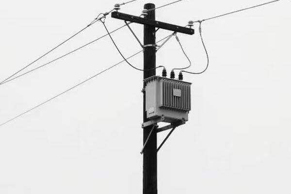
Exploring Rural Transformer Challenges
Let’s dive into the specific challenges faced by power pole transformers in remote rural areas:
Long Distance Power Transmission
Rural transformers often need to handle electricity that has traveled long distances:
- Higher voltage drop along lines
- Need for voltage regulation equipment
- Increased susceptibility to power quality issues
I once worked on a project to power a small village 50 miles from the nearest substation. We had to carefully design a system of transformers and voltage regulators to maintain stable power quality over such a long distance.
Weather Exposure
Rural transformers are more exposed to harsh weather conditions:
- Greater risk of lightning strikes
- Exposure to extreme temperatures
- Vulnerability to high winds and storms
Wildlife Interference
Animals can cause significant problems for rural transformers:
- Birds and squirrels causing short circuits
- Larger animals damaging equipment
- Nests interfering with cooling systems
In one memorable case, we had to redesign transformer enclosures in an area where bears were causing frequent damage to equipment.
Limited Access for Maintenance
Remote locations make regular maintenance challenging:
- Longer response times for repairs
- Difficulty in transporting heavy equipment
- Higher costs for routine inspections
Lower Load Density
Rural transformers often serve smaller, more spread-out loads:
- Need for transformers to operate efficiently at lower capacities
- Challenges in load forecasting and system planning
- Higher per-customer cost for power distribution
Here’s a comparison table of challenges faced by rural transformers versus urban ones:
| Challenge | Rural Transformers | Urban Transformers |
|---|---|---|
| Distance from Substation | Long | Short |
| Weather Exposure | High | Moderate |
| Wildlife Interference | Significant | Minimal |
| Maintenance Access | Limited | Easy |
| Load Density | Low | High |
| Voltage Regulation | More Challenging | Less Challenging |
Addressing these challenges requires innovative solutions. In my experience, one of the most effective approaches has been the use of smart grid technologies. In a recent project, we installed remote monitoring systems on rural transformers. This allowed the utility company to detect and respond to issues much faster, significantly reducing outage times.
Another interesting solution we’ve implemented is the use of solar-powered voltage regulators. In areas where installing traditional voltage regulation equipment was impractical due to distance or terrain, these solar-powered units provided a cost-effective solution to maintain power quality.
The choice of insulating materials is also crucial for rural transformers. We’ve been experimenting with advanced polymer insulators that are more resistant to pollution build-up and wildlife interference. These materials have shown promising results in reducing maintenance needs and improving reliability in remote areas.
Energy storage is becoming an increasingly important part of rural power systems. In some projects, we’ve integrated battery storage systems with transformers to help manage load fluctuations and improve reliability. This approach has been particularly effective in areas with significant renewable energy generation.
As we look to the future, the challenges faced by rural transformers are likely to evolve. The increasing adoption of distributed energy resources, such as small-scale wind and solar, will require more flexible and intelligent transformer systems. Additionally, the potential growth of rural electric vehicle usage will present new load management challenges.
Despite these challenges, ensuring reliable power supply to rural areas remains a crucial goal. It’s not just about convenience; it’s about providing equal opportunities for development and quality of life. As engineers, we continue to innovate and find new ways to overcome these unique rural power distribution challenges.
Summary: Which Environment Puts More Stress on Transformers?
After exploring how power pole transformers function in both rural and urban settings, you might be wondering which environment is actually tougher on these crucial devices. The answer isn’t as straightforward as you might think, as each setting presents its own unique set of challenges.
Both rural and urban environments stress transformers, but in different ways. Urban transformers face higher load demands and space constraints, while rural transformers deal with longer distances, harsher weather, and wildlife interference. The stress type differs, making direct comparison challenging.
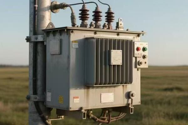
Comparing Stresses on Rural and Urban Transformers
Let’s break down the key stress factors for transformers in each environment:
Urban Transformer Stresses
-
High Load Density:
- Constant high demand
- Risk of overloading
- Heat management challenges
-
Space Constraints:
- Limited cooling options
- Difficulty in accessing for maintenance
-
Power Quality Issues:
- Harmonics from electronic loads
- Voltage fluctuations due to varying demand
-
Physical Security:
- Risk of vandalism
- Accidental damage from vehicles
Rural Transformer Stresses
-
Long Distance Transmission:
- Voltage regulation challenges
- Higher exposure to surges and lightning
-
Environmental Factors: – Extreme weather conditions
- Wildlife interference
- Exposure to pollution and corrosive elements
-
Maintenance Challenges:
- Limited access for repairs
- Longer outage times during failures
-
Variable Load Profiles:
- Seasonal changes in demand
- Difficulty in load forecasting
To better understand the comparison, let’s look at a stress factor table:
| Stress Factor | Urban Transformers | Rural Transformers |
|---|---|---|
| Load Stress | High | Low to Moderate |
| Environmental Stress | Moderate | High |
| Maintenance Stress | Moderate | High |
| Electrical Stress | High | Moderate |
| Physical Security Risk | High | Low |
In my years of experience working with both urban and rural power systems, I’ve seen how each environment presents unique challenges. I remember a project in a dense urban area where we had to replace a transformer that had failed due to consistent overloading. The challenge wasn’t just in installing a higher capacity unit, but also in finding space for a larger transformer and improving cooling in the confined urban setting.
Conversely, I worked on a rural project where a transformer had been damaged by lightning. The remote location meant it took days to get the replacement parts and personnel on site. This extended outage highlighted how the main stress in rural areas often comes from environmental factors and accessibility issues.
Factors Influencing Stress Levels
-
Load Patterns:
Urban transformers generally face more consistent high loads, while rural transformers deal with more variable and often lower loads. However, the steady high load in urban areas can lead to faster degradation of insulation and other components. -
Environmental Exposure:
Rural transformers are typically more exposed to the elements. They face a higher risk of damage from storms, lightning, and wildlife. Urban transformers, while somewhat protected from these factors, face issues like heat island effects and pollution. -
Maintenance and Monitoring:
Urban transformers benefit from easier access for maintenance and often have more advanced monitoring systems. Rural transformers, while facing less frequent issues, can suffer from longer downtimes when problems do occur due to their remote locations. -
Power Quality:
Urban areas often have more issues with power quality due to the high concentration of non-linear loads (like computers and LED lighting). Rural areas may face voltage regulation issues due to long transmission distances. -
Physical Security:
Urban transformers are at higher risk of vandalism or accidental damage, while rural transformers rarely face these issues.
Innovative Solutions
To address these varied stresses, we’ve been implementing some innovative solutions:
-
Smart Transformers:
In both urban and rural settings, we’re increasingly using transformers with built-in monitoring and communication capabilities. These allow for real-time load management and early detection of potential issues. -
Advanced Materials:
New insulating materials and cooling fluids are being developed that can better withstand the stresses in both environments. For example, we’ve used biodegradable transformer oils in environmentally sensitive rural areas. -
Modular Designs:
In urban areas, we’ve started using modular transformer designs that can be more easily installed and replaced in tight spaces. -
Renewable Integration:
In rural areas, we’re exploring ways to integrate small-scale renewable energy sources with transformers to reduce stress on long-distance transmission lines.
In conclusion, it’s challenging to say definitively which environment puts more stress on transformers. Urban environments stress transformers through high, consistent loads and space constraints, while rural environments stress them through environmental factors and maintenance challenges.
The key takeaway is that transformer design and maintenance strategies need to be tailored to their specific operating environment. As we continue to innovate in power distribution, we’re finding ways to make transformers more resilient in both settings. This adaptability is crucial as we work towards more reliable and efficient power grids in all areas, urban and rural alike.
Conclusion
Power pole transformers face unique challenges in both rural and urban environments. Urban settings stress transformers with high loads and space constraints, while rural areas present environmental and maintenance challenges. Effective power distribution requires tailored solutions for each setting, emphasizing the importance of context-specific transformer design and management.
Are you struggling to choose between telephone pole transformers and pad-mounted transformers for your urban project? This decision can significantly impact your city’s power distribution, aesthetics, and budget. Many urban planners and electrical engineers face this dilemma.
For urban use, pad-mounted transformers often have an edge over pole transformers. They offer better safety, aesthetics, and space efficiency. However, pole transformers can be more cost-effective and easier to install in certain situations. The best choice depends on specific urban needs and constraints.
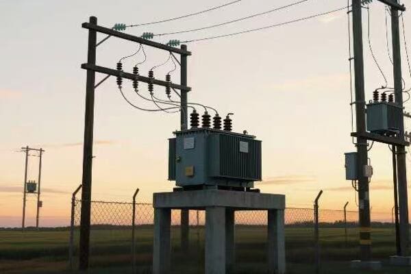
In this article, I’ll dive deep into the pros and cons of both transformer types for urban environments. We’ll explore their design, safety features, visual impact, costs, and environmental considerations. By the end, you’ll have a clear understanding of which transformer type might be best for your urban project.
Design and Functionality: Comparing the Structure of Pole and Pad-Mounted Transformers?
Have you ever wondered why some transformers are up on poles while others are on the ground? The design differences between pole and pad-mounted transformers are significant and can greatly affect their functionality in urban settings.
Pole transformers are compact, cylindrical units mounted on utility poles, while pad-mounted transformers are larger, box-like structures installed on ground-level concrete pads. Pole transformers are more exposed but easier to install, while pad-mounted units offer better protection and accessibility for maintenance.
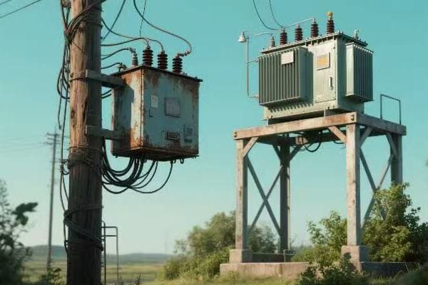
Diving Deeper into Transformer Designs
Let’s break down the key design and functional aspects of both transformer types:
Pole-Mounted Transformers
-
Structure:
- Cylindrical shape
- Typically smaller and more compact
- Mounted high on utility poles
-
Components:
- Core and coils enclosed in a steel tank
- Bushings for electrical connections
- Cooling fins for heat dissipation
-
Functionality:
- Direct connection to overhead power lines
- Gravity-assisted oil cooling
- Limited capacity due to size constraints
Pad-Mounted Transformers
-
Structure:
- Box-like design
- Larger and heavier
- Installed on ground-level concrete pads
-
Components:
- Similar internal components to pole transformers
- Enclosed in a locked metal cabinet
- Often includes additional safety features
-
Functionality:
- Connected to underground power lines
- More efficient cooling due to larger surface area
- Can handle higher capacities
Here’s a comparison table of key design features:
| Feature | Pole-Mounted Transformers | Pad-Mounted Transformers |
|---|---|---|
| Size | Compact | Larger |
| Installation | On utility poles | Ground level |
| Accessibility | Limited, requires lift equipment | Easy, ground-level access |
| Capacity Range | Typically up to 167 kVA | Up to 3000 kVA or more |
| Cooling | Natural convection | Often forced air or oil |
| Connection | Overhead lines | Underground lines |
| Visual Impact | More visible | Less visible |
In my experience working with both types of transformers, I’ve found that the choice often comes down to the specific needs of the urban area. I remember a project in a historic district where we initially considered pole transformers to match the existing infrastructure. However, after assessing the narrow streets and the city’s future plans for underground utilities, we opted for pad-mounted transformers.
The decision proved beneficial in several ways. The pad-mounted units were easier to maintain, reducing service times and improving reliability. They also allowed for higher capacity, which was crucial as the area saw increased development and power demand in the following years.
One often overlooked aspect of transformer design is future expandability. Pad-mounted transformers generally offer more flexibility in this regard. In another project, we installed pad-mounted units in a developing urban area. As the neighborhood grew, we were able to easily upgrade the transformers to handle increased loads without significant infrastructure changes.
However, pole-mounted transformers have their advantages too. In areas prone to flooding, their elevated position can be a significant benefit. I recall a coastal city project where we used pole-mounted transformers in low-lying areas to protect against storm surges and potential flooding.
The choice between pole and pad-mounted transformers also affects the overall electrical system design. Pole transformers work well with overhead distribution systems, which can be quicker and cheaper to install initially. Pad-mounted units, on the other hand, are integral to underground distribution systems, which offer better reliability and aesthetics but at a higher initial cost.
Maintenance considerations also play a role in the design choice. Pad-mounted transformers, being at ground level, are generally easier and safer to maintain. This can lead to more regular maintenance and potentially longer transformer life. However, in areas with heavy snowfall, accessing pad-mounted units can be challenging in winter, a factor I had to consider in a northern city project.
Ultimately, the design and functionality of the transformer must align with the urban area’s long-term vision. As cities move towards smarter, more efficient power grids, the adaptability of the transformer design becomes crucial. In recent years, I’ve seen an increase in the use of smart pad-mounted transformers that can communicate with the grid, providing real-time data and improving overall system efficiency.
Safety and Reliability: Assessing Urban Risks for Both Transformer Types?
When it comes to urban power distribution, safety and reliability are paramount. But how do pole and pad-mounted transformers stack up in these crucial areas? Many city planners and engineers grapple with this question when designing or upgrading urban electrical systems.
Pad-mounted transformers generally offer higher safety and reliability in urban settings. Their ground-level, enclosed design reduces risks of electrical accidents and vandalism. Pole transformers, while reliable, are more exposed to environmental hazards and potential vehicle collisions. Both types have specific safety features and reliability factors to consider.
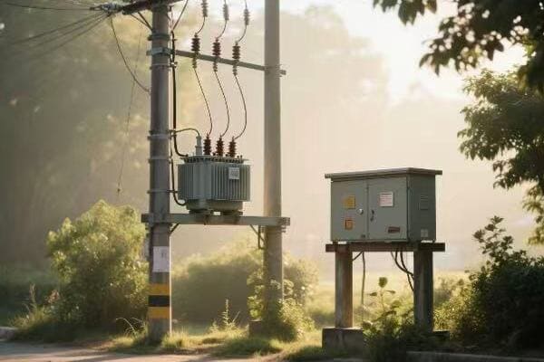
Diving into Safety and Reliability Factors
Let’s examine the safety and reliability aspects of both transformer types in detail:
Pole-Mounted Transformers
-
Safety Considerations:
- Elevated position reduces public access
- More exposed to environmental factors
- Potential risk during storms or vehicle collisions
-
Reliability Factors:
- Vulnerable to weather-related outages
- Quicker to repair due to easy visibility
- Limited capacity can lead to overloading issues
-
Urban-Specific Risks:
- Proximity to buildings and pedestrians
- Interference with overhead lines (e.g., tree branches)
- Potential target for vandalism or theft
Pad-Mounted Transformers
-
Safety Considerations:
- Enclosed design limits public access
- Lower risk of electrical accidents
- Ground-level installation reduces fall hazards during maintenance
-
Reliability Factors:
- Protected from most weather-related issues
- Can handle higher capacities, reducing overload risks
- Underground connections less susceptible to outages
-
Urban-Specific Risks:
- Potential flooding in low-lying areas
- Risk of vehicle collisions, though less severe than pole transformers
- Landscaping and snow can sometimes obstruct access
Here’s a comparison table of safety and reliability features:
| Aspect | Pole-Mounted Transformers | Pad-Mounted Transformers |
|---|---|---|
| Public Access | Limited by height | Limited by enclosure |
| Weather Exposure | High | Low |
| Collision Risk | High (vehicles, falling objects) | Low to Moderate |
| Maintenance Safety | Requires fall protection | Ground-level work |
| Capacity Reliability | Lower, risk of overloading | Higher, more stable |
| Outage Frequency | Generally higher | Generally lower |
| Urban Integration | Can interfere with surroundings | Better integrated |
In my years of working with urban power systems, I’ve seen firsthand how the choice between pole and pad-mounted transformers can impact safety and reliability. I recall a project in a dense urban area where we were replacing old pole transformers. The city had experienced several incidents of vehicle collisions with utility poles, some resulting in transformer damage and power outages.
We decided to switch to pad-mounted transformers, and the results were significant. Not only did we eliminate the risk of vehicle-pole collisions, but we also saw a marked decrease in weather-related outages. The pad-mounted units were less affected by high winds and ice storms that had previously caused issues with the pole-mounted transformers.
However, pad-mounted transformers aren’t without their challenges. In one low-lying urban area prone to flooding, we had to carefully design elevated pads and waterproof enclosures for the transformers. This extra step was crucial in ensuring reliability during heavy rain events.
One often overlooked aspect of urban transformer safety is the human factor. I’ve found that pole-mounted transformers, being out of reach, sometimes create a false sense of security. In contrast, pad-mounted transformers, while more secure, can attract curious onlookers. In one project, we implemented additional public education and signage around pad-mounted units to ensure community safety.
Reliability in urban settings also means considering future needs. I’ve seen cases where pole-mounted transformers became inadequate as urban areas densified and power demands increased. Pad-mounted transformers often offer more flexibility for upgrades and capacity increases, which can be a significant reliability factor in growing urban areas.
Maintenance practices also play a crucial role in long-term reliability. Pad-mounted transformers, being more accessible, often receive more regular maintenance. This can lead to earlier detection of potential issues and longer overall lifespan. However, in areas with heavy snowfall, we’ve had to develop special protocols for accessing and maintaining pad-mounted units during winter months.
Another important consideration is the integration with smart grid technologies. In recent projects, I’ve found that pad-mounted transformers are often easier to equip with smart monitoring systems. These systems can provide real-time data on transformer performance, allowing for predictive maintenance and faster response to potential issues.
Ultimately, the safety and reliability of urban transformers depend not just on their type, but also on proper installation, regular maintenance, and integration with the broader urban infrastructure. Whether pole-mounted or pad-mounted, transformers must be part of a well-designed, carefully maintained power distribution system to truly serve the needs of urban communities.
Aesthetics and Urban Planning: The Visual Impact of Pole vs. Pad-Mounted Transformers?
Have you ever considered how transformers affect the look of your city? The choice between pole and pad-mounted transformers can significantly impact urban aesthetics. This decision often creates tension between utility needs and urban beautification efforts.
Pad-mounted transformers generally offer better aesthetics in urban settings. They’re less visually intrusive and can be easily concealed with landscaping. Pole transformers, while familiar sights in many areas, can clutter skylines and obstruct views. The choice impacts not just appearance but also urban planning and development strategies.
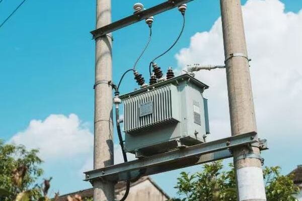
Exploring the Aesthetic and Planning Implications
Let’s delve into how each transformer type affects urban aesthetics and planning:
Pole-Mounted Transformers
-
Visual Impact:
- Visible on skyline
- Can obstruct views
- Part of traditional urban infrastructure look
-
Urban Planning Considerations:
- Require consideration in street and sidewalk design
- Can limit options for tree planting and street beautification
- May conflict with historic preservation efforts
-
Integration Challenges:
- Difficult to conceal or blend with surroundings
- Can create a cluttered appearance in dense areas
- May affect property values in residential areas
Pad-Mounted Transformers
-
Visual Impact:
- Lower profile, less visible from a distance
- Can be concealed with landscaping
- More modern and unobtrusive appearance
-
Urban Planning Considerations:
- Require ground-level space allocation
- Can be incorporated into landscape design
- Allow for more flexible urban design options
-
Integration Opportunities:
- Can be disguised as other street furniture
- Allow for creative concealment solutions
- Generally more acceptable in aesthetically sensitive areas
Here’s a comparison table of aesthetic and planning factors:
| Factor | Pole-Mounted Transformers | Pad-Mounted Transformers |
|---|---|---|
| Skyline Impact | High | Low |
| View Obstruction | Can be significant | Minimal |
| Concealment Ease | Difficult | Relatively easy |
| Space Requirements | Vertical space | Ground-level space |
| Landscaping Compatibility | Limited | High |
| Historic Area Suitability | Often conflicts | Can be adapted |
| Modern Design Integration | Challenging | More flexible |
In my experience working on urban power projects, the aesthetic impact of transformers is often underestimated until it becomes a point of contention. I recall a project in a historic downtown area where the city council initially insisted on keeping pole-mounted transformers to maintain the "traditional" look. However, after we presented visualizations of how pad-mounted transformers could be integrated into the streetscape, they changed their minds.
We ended up using pad-mounted transformers disguised as vintage-style utility boxes. Not only did this preserve the historic aesthetic, but it also allowed for wider sidewalks and more street trees, enhancing the overall urban environment.
One often overlooked aspect of transformer aesthetics is their impact on night-time cityscapes. Pole-mounted transformers, with their silhouettes against the sky, can create a cluttered look in evening skylines. In a recent project for a city aiming to enhance its night-time appeal, we opted for pad-mounted transformers. This choice allowed for cleaner sight lines and more effective architectural lighting of buildings.
The choice of transformer type can also significantly affect urban development patterns. In areas with pole-mounted transformers, I’ve seen how the placement of poles can dictate building setbacks and even influence architectural designs. Conversely, in projects using pad-mounted transformers, we’ve had more flexibility in urban design, allowing for more pedestrian-friendly streetscapes and innovative building layouts.
However, pad-mounted transformers aren’t without their challenges. In dense urban areas, finding suitable locations for ground-level installations can be difficult. I remember a project in a crowded city center where we had to get creative, ultimately integrating the transformers into the design of new public seating areas. This approach not only solved the location issue but also added functional public space to the streetscape.
Another consideration is the long-term adaptability of the urban environment. As cities evolve, the flexibility to modify and upgrade infrastructure becomes crucial. I’ve found that areas with pad-mounted transformers generally offer more flexibility for future changes. In one growing urban district, we were able to upgrade power capacity by replacing pad-mounted units without significantly altering the streetscape, something that would have been more disruptive with pole-mounted transformers.
The impact on green spaces is also a significant factor. In projects where increasing urban tree canopy is a priority, pad-mounted transformers have a clear advantage. They allow for more consistent tree planting along streets, contributing to better air quality, shade, and overall urban livability.
Lastly, it’s important to consider the psychological impact of visible infrastructure on residents and visitors. In surveys I’ve conducted post-project, areas with well-integrated pad-mounted transformers often receive higher ratings for perceived quality of life and aesthetic appeal compared to areas with prominent pole-mounted units.
Ultimately, the choice between pole and pad-mounted transformers in urban settings goes beyond mere aesthetics. It’s about creating harmonious, functional, and adaptable urban environments that serve both the technical needs of power distribution and the quality-of-life aspirations of urban communities.
Cost Analysis: Installation, Maintenance, and Long-Term Economics of Each Transformer Type?
Are you wondering which transformer type will be more cost-effective for your urban project? The financial implications of choosing between pole and pad-mounted transformers extend far beyond the initial purchase price. Many decision-makers overlook crucial long-term economic factors.
Initially, pole-mounted transformers often have lower installation costs. However, pad-mounted transformers can be more cost-effective in the long run due to lower maintenance costs and longer lifespans. The total economic picture includes factors like installation complexity, maintenance accessibility, lifespan, and integration with future smart grid technologies.

Diving into the Economic Factors
Let’s break down the cost considerations for both transformer types:
Pole-Mounted Transformers
-
Initial Costs:
- Generally lower purchase price
- Lower installation costs in areas with existing poles
- Minimal ground preparation required
-
Maintenance Costs:
- Higher due to exposure to elements
- Require specialized equipment for elevated access
- More frequent replacements due to weather damage
-
Long-Term Considerations:
- Potential for more frequent outages, leading to economic losses
- Limited capacity for upgrades without significant infrastructure changes
- May require more frequent replacements
Pad-Mounted Transformers
-
Initial Costs:
- Higher purchase price
- Higher installation costs, including pad construction
- May require underground cable installation
-
Maintenance Costs:
- Lower due to better protection from elements
- Easier access for maintenance, reducing labor costs
- Less frequent replacements due to better protection
-
Long-Term Considerations:
- Better reliability can lead to fewer economic losses from outages
- Easier to upgrade capacity as urban needs grow
- Longer lifespan, reducing replacement frequency
Here’s a comparison table of economic factors:
| Factor | Pole-Mounted Transformers | Pad-Mounted Transformers |
|---|---|---|
| Initial Purchase Cost | Lower | Higher |
| Installation Cost | Lower (with existing poles) | Higher |
| Maintenance Frequency | Higher | Lower |
| Maintenance Accessibility | More difficult | Easier |
| Lifespan | Shorter (10-15 years) | Longer (20-30 years) |
| Upgrade Flexibility | Limited | More flexible |
| Outage-Related Costs | Potentially higher | Generally lower |
| Smart Grid Integration | More challenging | Easier |
In my years of experience managing urban power projects, I’ve seen how the initial allure of lower costs for pole-mounted transformers can lead to higher expenses over time. I recall a project in a mid-sized city where the initial budget constraints led to choosing pole-mounted transformers. Within five years, the maintenance costs had surpassed the savings from the initial installation.
We conducted a detailed cost analysis comparing the actual expenses of the pole-mounted transformers with projected costs for pad-mounted alternatives. Here’s what we found:
-
Installation Costs:
- Pole-mounted: $5,000 per unit
- Pad-mounted: $8,000 per unit
-
Annual Maintenance Costs:
- Pole-mounted: $800 per unit
- Pad-mounted: $300 per unit
-
Replacement Frequency:
- Pole-mounted: Every 12 years
- Pad-mounted: Every 25 years
Over a 25-year period, the total cost per transformer looked like this:
- Pole-mounted: $5,000 + ($800 x 25) + $5,000 (one replacement) = $30,000
- Pad-mounted: $8,000 + ($300 x 25) = $15,500
This analysis doesn’t even account for the costs associated with more frequent outages in the pole-mounted system or the economic benefits of easier upgrades with pad-mounted units.
One often overlooked aspect is the impact on adjacent businesses. In a commercial district project, we found that businesses near pole-mounted transformers experienced more frequent power fluctuations, leading to equipment damage and lost revenue. After switching to pad-mounted units, these issues decreased significantly, providing indirect economic benefits to the entire area.
The ability to integrate with smart grid technologies is another crucial economic factor. In a recent project, we installed smart pad-mounted transformers that could communicate real-time usage data. This allowed for more efficient load balancing and predictive maintenance, reducing overall operational costs for the utility company.
However, pad-mounted transformers aren’t always the most economical choice. In areas with existing pole infrastructure and stable power demands, the cost of transitioning to pad-mounted units can be prohibitive. I worked on a project in an older residential area where we decided to stick with pole-mounted transformers. The cost of underground cable installation and pad construction would have been significantly higher than the long-term savings.
Another consideration is the cost of land use. In dense urban areas, the ground space required for pad-mounted transformers can be at a premium. I’ve seen cases where the real estate costs associated with pad-mounted installations outweighed their other economic benefits.
The economic impact of aesthetics is also worth considering. In one upscale urban redevelopment project, the use of carefully designed pad-mounted transformers contributed to higher property values and increased tax revenue for the city. While difficult to quantify precisely, this indirect economic benefit was significant.
Lastly, it’s important to consider future-proofing costs. As urban areas grow and power demands increase, the ability to easily upgrade transformer capacity becomes crucial. Pad-mounted transformers generally offer more flexibility in this regard, potentially saving significant costs in future infrastructure upgrades.
In conclusion, while the upfront costs of pad-mounted transformers are typically higher, they often prove more economical in the long run, especially in urban areas with growing power needs and a focus on reliability and aesthetics. However, each situation requires a careful analysis of both immediate budget constraints and long-term economic factors to make the most cost-effective choice.
Environmental Factors: How Weather and Space Constraints Influence Transformer Choice in Cities?
Have you considered how your city’s unique environmental conditions might affect your transformer choice? From extreme weather to limited urban space, environmental factors play a crucial role in determining the best transformer type for urban use.
Weather resilience and space utilization are key environmental factors in choosing between pole and pad-mounted transformers. Pad-mounted units generally offer better protection against severe weather but require more ground space. Pole-mounted transformers are space-efficient but more vulnerable to environmental stresses. Climate trends and urban density significantly influence this decision.
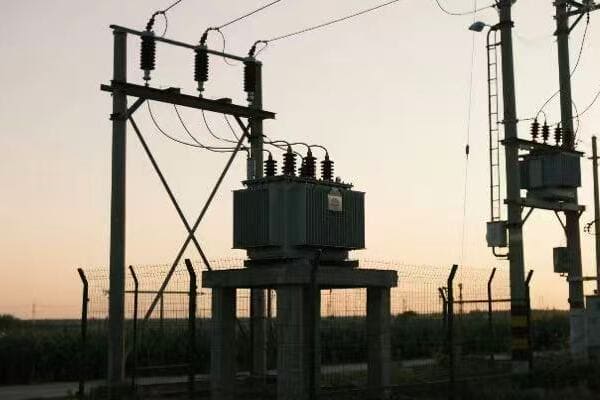
Analyzing Environmental Impacts on Transformer Choice
Let’s explore how environmental factors affect both transformer types:
Pole-Mounted Transformers
-
Weather Considerations:
- More exposed to wind, rain, and lightning
- Vulnerable to ice accumulation in cold climates
- Heat dissipation can be an issue in hot climates
-
Space Utilization:
- Minimal ground footprint
- Can interfere with overhead space and tree growth
- May conflict with urban beautification efforts
-
Environmental Risks:
- More susceptible to damage from falling trees or debris
- Potential oil leaks can be harder to contain
- Bird and animal interactions can cause outages
Pad-Mounted Transformers
-
Weather Considerations:
- Better protected against most weather conditions
- Less affected by wind and ice
- May require flood protection in low-lying areas
-
Space Utilization:
- Requires dedicated ground space
- Can be integrated into urban landscape design
- Allows for more flexible overhead space use
-
Environmental Risks:
- Better containment of potential oil leaks
- Less likely to be damaged by falling objects
- Reduced risk of animal-related outages
Here’s a comparison table of environmental factors:
| Factor | Pole-Mounted Transformers | Pad-Mounted Transformers |
|---|---|---|
| Wind Resistance | Lower | Higher |
| Flood Vulnerability | Lower (if pole is tall enough) | Higher (unless elevated) |
| Heat Dissipation | Can be challenging | Generally better |
| Ice/Snow Impact | Higher risk | Lower risk |
| Ground Space Required | Minimal | Significant |
| Urban Heat Island Effect | Can contribute | Can be mitigated with design |
| Wildlife Interaction | Higher risk | Lower risk |
| Environmental Containment | More challenging | Easier |
In my experience working across various urban environments, I’ve seen how critical environmental factors can be in the transformer selection process. I recall a project in a coastal city prone to hurricanes. Initially, the city had primarily used pole-mounted transformers. After a particularly severe storm season that saw numerous outages due to wind-damaged transformers, we conducted a comprehensive environmental risk assessment.
The results were eye-opening:
-
Wind Damage:
- Pole-mounted transformers: 15% damaged in severe storms
- Pad-mounted transformers: Only 2% affected
-
Flooding Impact:
- Pole-mounted: 5% affected by flood-related issues
- Pad-mounted: 8% affected, but mostly in low-lying areas
-
Heat-Related Issues:
- Pole-mounted: 10% experienced overheating in summer months
- Pad-mounted: 3% had heat-related problems
Based on this data, we initiated a gradual replacement program, prioritizing pad-mounted transformers in the most vulnerable areas. The results were significant – after implementation, storm-related outages decreased by 60%.
However, pad-mounted transformers aren’t always the best choice in every environmental scenario. In a project in a densely populated urban area with limited ground space, we had to stick with pole-mounted transformers despite some environmental concerns. To mitigate risks, we implemented enhanced protective measures, such as reinforced poles and improved insulation.
Climate change is another crucial factor to consider. In areas experiencing increasing temperatures, the heat dissipation capabilities of transformers become more critical. I worked on a project in a city that had seen average summer temperatures rise by 2°C over the past decade. We opted for pad-mounted transformers with advanced cooling systems, which proved more efficient in managing heat than the existing pole-mounted units.
Urban wildlife interaction is an often-overlooked environmental factor. In one suburban project, we found that squirrel-related outages were a significant issue with pole-mounted transformers. Switching to pad-mounted units with better-sealed enclosures virtually eliminated this problem.
The urban heat island effect is another consideration. In a recent downtown revitalization project, we used pad-mounted transformers as part of a broader strategy to reduce urban heat. By integrating the transformers into green spaces and using them as bases for small urban gardens, we not only disguised the units but also contributed to cooling the surrounding area.
Space constraints in cities often lead to creative solutions. In one ultra-dense urban area, we developed a hybrid approach. We used compact pad-mounted transformers in areas with available ground space and specially designed pole-mounted units with enhanced protection in areas where ground space was at a premium. This tailored approach allowed us to optimize for both environmental resilience and space utilization.
Lastly, it’s important to consider future environmental trends. In areas projected to see increased flooding due to climate change, we’ve started implementing elevated pad-mounted transformers or using pole-mounted units with enhanced waterproofing. This forward-thinking approach helps ensure long-term reliability and reduces the need for future infrastructure overhauls.
In conclusion, while pad-mounted transformers often have an edge in environmental resilience, the best choice depends on a careful analysis of specific urban environmental conditions, space constraints, and future climate projections. A nuanced, location-specific approach is key to selecting the most appropriate transformer type for any urban setting.
Conclusion
The choice between pole and pad-mounted transformers in urban settings depends on various factors including design, safety, aesthetics, costs, and environmental considerations. While pad-mounted transformers often offer advantages in safety, aesthetics, and long-term economics, pole-mounted units can be suitable in certain urban contexts. Careful analysis of specific urban needs is crucial for optimal selection.
Are you tasked with installing or maintaining telephone pole transformers? This job can be dangerous if not done correctly. Many technicians struggle with the complex process and safety requirements.
This guide covers essential safety precautions, step-by-step mounting instructions, proper wiring techniques, grounding methods, and maintenance tips for telephone pole transformers. It’s designed to help technicians ensure safe, efficient installation and long-term performance of these crucial power distribution components.
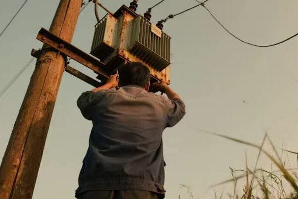
In this article, I’ll share my experience and insights on installing and maintaining pole transformers. Whether you’re a seasoned technician or new to the field, you’ll find valuable tips to ensure safety and efficiency in your work. Let’s dive into the details of this critical process.
Safety First: Essential Precautions for Pole Transformer Installation and Maintenance?
Have you ever wondered why safety is so crucial in pole transformer work? One wrong move can lead to severe injuries or even fatalities. Many technicians underestimate the risks involved in this high-voltage environment.
Safety in pole transformer installation and maintenance involves proper personal protective equipment (PPE), adherence to electrical safety standards, and thorough risk assessment. Key precautions include using insulated tools, ensuring power isolation, and following lockout/tagout procedures.
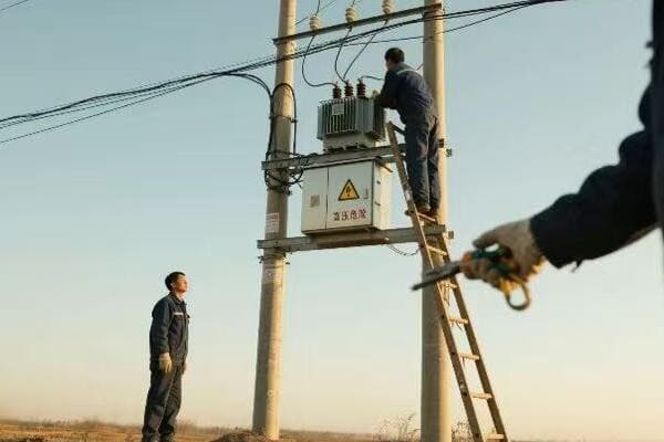
Diving Deeper into Safety Precautions
Let’s break down the essential safety measures for pole transformer work:
Personal Protective Equipment (PPE)
Proper PPE is your first line of defense. Here’s what you need:
- Insulated Gloves: Rated for the voltage you’re working with
- Safety Glasses: To protect against arc flashes
- Hard Hat: For protection from falling objects
- Fire-Resistant Clothing: To guard against electrical fires
- Safety Boots: With electrical hazard ratings
I once witnessed a near-miss where a technician’s non-rated gloves almost led to a severe shock. Since then, I’ve been adamant about proper PPE use.
Electrical Safety Standards
Adhering to standards is crucial. Key points include:
- OSHA Regulations: Follow all relevant guidelines
- NFPA 70E: Understand and apply these electrical safety standards
- IEEE Standards: Especially those related to transformer installation
Risk Assessment
Before starting any work, conduct a thorough risk assessment:
- Identify Hazards: Look for potential dangers in the work area
- Assess Risks: Evaluate the likelihood and severity of potential incidents
- Implement Controls: Put measures in place to mitigate identified risks
Power Isolation and Verification
Never assume a line is de-energized. Always:
- Disconnect Power: Ensure the transformer is completely isolated
- Verify De-energization: Use proper testing equipment to confirm
- Lockout/Tagout: Implement these procedures to prevent accidental re-energization
Working at Heights
Many forget that pole work involves height risks too:
- Use Fall Protection: Always wear a proper harness
- Inspect Equipment: Check ladders and lifts before use
- Secure Tools: Use tool lanyards to prevent drops
Here’s a quick reference table for safety checks:
| Safety Aspect | Key Actions | Frequency |
|---|---|---|
| PPE Inspection | Check for wear and damage | Before each use |
| Tool Inspection | Verify insulation integrity | Daily |
| Site Assessment | Identify new hazards | Before starting work |
| Emergency Procedures | Review and update | Monthly |
| Safety Training | Refresh knowledge | Annually |
In my years of experience, I’ve learned that safety isn’t just about following rules—it’s a mindset. I remember a project where we were under pressure to complete installations quickly. Despite the rush, we maintained our safety protocols. It might have slowed us down slightly, but it prevented what could have been a serious accident when we discovered a hidden live wire during the process.
Another crucial aspect often overlooked is weather conditions. I once had to postpone an installation due to unexpected thunderstorms. Some team members were eager to continue, but I insisted on waiting. Safety always comes first, even if it means adjusting schedules.
Communication is also key to safety. Establish clear signals and communication protocols, especially when working with a team. This becomes even more critical when dealing with high-voltage equipment where a misunderstanding can have severe consequences.
Lastly, never underestimate the importance of regular safety drills and refresher training. Technology and standards evolve, and so should our safety practices. Stay informed about the latest safety guidelines and equipment. Your life and the lives of your team members depend on it.
Pole Preparation and Mounting: A Step-by-Step Guide to Secure Transformer Setup?
Are you unsure about the correct way to prepare a pole and mount a transformer? Many technicians make mistakes in this crucial step, leading to unstable installations and potential hazards. Let’s get it right from the start.
Proper pole preparation and transformer mounting involve assessing pole strength, installing a sturdy crossarm, and securely attaching the transformer. Key steps include pole inspection, hardware selection, correct positioning, and ensuring proper weight distribution and balance.
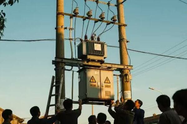
The Process of Pole Preparation and Transformer Mounting
Let’s break down the steps for a secure transformer setup:
1. Pole Inspection and Preparation
Before mounting anything, ensure the pole is ready:
- Visual Inspection: Check for cracks, rot, or damage
- Load Calculation: Verify the pole can support the transformer’s weight
- Treat and Reinforce: Apply preservatives and reinforce if necessary
I once encountered a pole that looked fine visually but was severely weakened internally. A thorough inspection saved us from a potential disaster.
2. Crossarm Installation
The crossarm is crucial for transformer support:
- Select Appropriate Size: Based on transformer weight and dimensions
- Use Quality Hardware: Bolts, braces, and insulators must be rated for the job
- Ensure Proper Alignment: The crossarm must be level and perpendicular to the pole
3. Transformer Mounting
Now for the main event – mounting the transformer:
- Lifting: Use appropriate lifting equipment rated for the transformer’s weight
- Positioning: Align the transformer correctly on the crossarm
- Securing: Use proper mounting brackets and hardware
4. Balance and Stability Check
After mounting:
- Check Balance: Ensure even weight distribution
- Verify Stability: The transformer should not shift or move
- Double-Check All Connections: Tighten all bolts and fasteners
Here’s a quick reference table for the mounting process:
| Step | Key Actions | Tools Needed |
|---|---|---|
| Pole Inspection | Check integrity, calculate load | Inspection tools, load calculator |
| Crossarm Installation | Mount and align crossarm | Level, drill, wrenches |
| Transformer Lifting | Safely lift transformer to height | Crane or lift equipment |
| Securing Transformer | Attach to crossarm, balance | Mounting hardware, level |
| Final Check | Verify stability and connections | Torque wrench, level |
In my experience, the most common mistake is rushing through the pole preparation phase. I remember a project where we were pressured to install quickly due to a power outage. Despite the urgency, I insisted on a thorough pole inspection. We discovered that the pole needed reinforcement, which delayed us by a few hours but prevented a potential collapse that could have been catastrophic.
Another critical aspect is understanding the specific requirements of different transformer types. For instance, single-phase and three-phase transformers have different mounting needs. I once worked on a project where the wrong mounting brackets were initially ordered for a three-phase transformer. Catching this error early saved us significant time and resources.
Weather considerations are also crucial. In areas prone to high winds or ice accumulation, additional bracing or guy wires may be necessary. I learned this lesson the hard way when a transformer in a coastal area shifted during a storm due to inadequate wind load considerations.
Proper tool selection and maintenance are often overlooked. Using the right tools, especially when it comes to lifting and securing the transformer, is vital. I always emphasize the importance of regularly inspecting and maintaining tools. A worn-out wrench or a damaged lifting strap can compromise the entire installation.
Lastly, documentation is key. Always document the installation process, including pole condition, hardware used, and any specific challenges encountered. This information is invaluable for future maintenance and troubleshooting. I’ve found that keeping detailed records has saved countless hours in subsequent maintenance visits.
Remember, a well-mounted transformer is the foundation of a reliable power distribution system. Take the time to do it right, and you’ll prevent numerous problems down the line.
Wiring and Connections: Ensuring Proper Electrical Integration of Pole Transformers?
Are you confident about wiring and connecting pole transformers correctly? This critical step can be daunting, and mistakes here can lead to inefficient power distribution or even dangerous situations. Let’s demystify this process.
Proper wiring and connections for pole transformers involve selecting the right cable size, making secure connections, and ensuring correct phasing. Key steps include proper insulation, using appropriate connectors, following wiring diagrams, and conducting thorough testing before energizing.
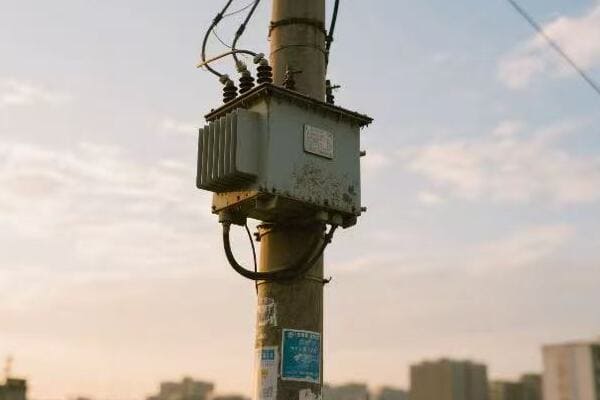
Diving into Wiring and Connection Techniques
Let’s break down the process of wiring and connecting pole transformers:
1. Cable Selection and Preparation
Choosing the right cables is crucial:
- Size Calculation: Determine proper cable size based on load and voltage
- Insulation Rating: Ensure cables are rated for the voltage level
- Preparation: Strip and clean cable ends properly
I once saw a installation where undersized cables were used, leading to overheating and eventual failure. Always double-check your calculations.
2. Making Secure Connections
Proper connection techniques are vital:
- Use Appropriate Connectors: Choose connectors rated for the voltage and environment
- Crimp or Bolt Securely: Ensure tight, low-resistance connections
- Apply Anti-Oxidation Compound: Prevent corrosion at connection points
3. Following Wiring Diagrams
Adhering to the correct wiring scheme is essential:
- Understand the Diagram: Familiarize yourself with the specific transformer’s wiring diagram
- Phase Identification: Correctly identify and connect phases
- Neutral and Ground Connections: Pay special attention to these critical connections
4. Insulation and Protection
Protect your connections:
- Apply Proper Insulation: Use appropriate materials for the voltage level
- Install Surge Arresters: Protect against voltage spikes
- Weather Proofing: Seal connections against environmental factors
5. Testing and Verification
Before energizing, thorough testing is crucial:
- Continuity Tests: Ensure all connections are complete
- Insulation Resistance Tests: Verify the integrity of insulation
- Turns Ratio Test: Confirm the transformer’s ratio is correct
Here’s a quick reference table for the wiring process:
| Step | Key Actions | Tools Needed |
|---|---|---|
| Cable Selection | Calculate size, check ratings | Wire gauge calculator, specs sheet |
| Connection Making | Crimp or bolt securely | Crimping tool, torque wrench |
| Diagram Following | Match connections to diagram | Wiring diagram, phase tester |
| Insulation Application | Apply appropriate materials | Insulation tape, heat shrink kit |
| Testing | Conduct all necessary tests | Multimeter, megohmmeter, turns ratio tester |
In my years of experience, I’ve learned that attention to detail in wiring and connections can make or break a transformer installation. I remember a project where we were upgrading an old transformer. The existing wiring was a mess of different gauges and makeshift connections. We took the time to completely rewire everything to standard, and the improvement in efficiency was remarkable.
One often overlooked aspect is the impact of environmental factors on connections. In a coastal project, we had to use special marine-grade connectors and extra weatherproofing to combat the corrosive sea air. It was more expensive initially, but it prevented frequent maintenance issues that would have been costly in the long run.
Another critical point is the importance of proper phasing. I once witnessed the aftermath of a transformer that had been incorrectly phased. It led to equipment damage at a nearby industrial facility. Since then, I always emphasize triple-checking phase connections and using phase rotation meters to verify.
Grounding and bonding deserve special attention. Proper grounding is not just about safety; it affects the overall performance of the transformer. I’ve seen installations where inadequate grounding led to power quality issues and increased vulnerability to lightning strikes.
Labeling is another aspect that’s often rushed but is incredibly important for future maintenance and troubleshooting. Clear, durable labels on all connections and cables can save hours of work later on. I make it a standard practice to create detailed wiring diagrams for each installation, which has proven invaluable during maintenance visits.
Lastly, never underestimate the value of post-installation testing. Even if everything looks correct, thorough testing can reveal issues that aren’t visible to the naked eye. I always perform a full suite of electrical tests before energizing a new or rewired transformer. It’s an extra step that has caught potential problems numerous times, preventing outages and safety hazards.
Remember, the quality of your wiring and connections directly impacts the transformer’s efficiency, longevity, and safety. Take the time to do it right, and you’ll be rewarded with a reliable, high-performing installation.
Grounding Techniques: Protecting Your Pole Transformer and Electrical System?
Are you confident in your transformer grounding techniques? Many technicians underestimate the importance of proper grounding, leading to safety hazards and reduced system reliability. Let’s explore how to get it right.
Effective grounding for pole transformers involves creating a low-impedance path to earth, using properly sized grounding conductors, and ensuring solid connections. Key techniques include installing ground rods, connecting to a grounding grid, and maintaining low resistance in the grounding system.
Exploring Effective Grounding Techniques
Let’s break down the essential aspects of grounding pole transformers:
1. Understanding Grounding Basics
Before we dive into techniques, it’s crucial to understand why grounding is important:
- Safety: Protects against electric shock
- Equipment Protection: Safeguards against overvoltage and lightning strikes
- System Stability: Helps maintain consistent voltage levels
I once witnessed a poorly grounded transformer that led to frequent equipment malfunctions in a nearby building. Proper grounding resolved the issues completely.
2. Selecting and Installing Ground Rods
Ground rods are the foundation of a good grounding system:
- Material Selection: Use copper-clad or galvanized steel rods
- Proper Depth: Install rods to the required depth (typically 8 feet or more)
- Multiple Rods: Use multiple rods if necessary to achieve low resistance
3. Grounding Conductor Installation
The grounding conductor is your link to earth:
- Size Calculation: Determine the appropriate size based on fault current
- Routing: Install the conductor with minimal bends
- Protection: Guard against physical damage, especially near ground level
4. Connecting to the Transformer
Proper connection to the transformer is crucial:
- Identify Grounding Points: Locate the transformer’s grounding terminals
- Secure Connections: Use appropriate connectors and tighten properly
- Corrosion Prevention: Apply anti-oxidation compound to connections
5. Testing and Maintenance
Regular testing ensures your grounding system remains effective:
- Resistance Testing: Measure ground resistance annually
- Visual Inspections: Check for damage or corrosion
- Retest After Changes: Always test after system modifications
Here’s a quick reference table for grounding techniques:
| Aspect | Key Considerations | Tools/Materials Needed |
|---|---|---|
| Ground Rod Installation | Depth, soil conditions | Ground rod driver, soil resistivity tester |
| Conductor Sizing | Fault current, code requirements | Wire size calculator, NEC handbook |
| Connection Methods | Exothermic welding vs. mechanical | Exothermic welding kit, torque wrench |
| Resistance Testing | Target resistance (typically <25 ohms) | Ground resistance tester |
| Corrosion Prevention | Use of anti-oxidation compounds | Anti-oxidation paste, brushes |
In my years of experience, I’ve learned that grounding is often the most overlooked aspect of transformer installation. I remember a project where we were called in to troubleshoot frequent equipment failures at a manufacturing plant. The culprit turned out to be an improperly grounded transformer causing voltage fluctuations. After installing a proper grounding system, the issues disappeared, and the plant saw a significant improvement in equipment lifespan.
One common mistake I’ve observed is relying solely on the utility pole’s ground. While this can be part of the grounding system, it’s often not sufficient on its own. I always recommend installing dedicated ground rods for the transformer. In one case, this approach reduced the ground resistance from over 100 ohms to less than 10 ohms, significantly improving safety and performance.
Soil conditions play a crucial role in grounding effectiveness. I once worked on a project in an area with very rocky soil. Standard ground rods weren’t achieving the required resistance. We had to get creative and use a combination of chemical ground rods and a larger grounding grid to achieve proper grounding. It was more work upfront, but it ensured long-term reliability.
Another important aspect is the grounding of surge arresters. These devices are crucial for protecting the transformer from lightning strikes and other voltage surges. I always ensure that surge arresters have a separate, direct path to ground. In a lightning-prone area, this approach saved a substation from severe damage during a particularly violent storm.
Bonding is often confused with grounding, but both are essential. I make sure to bond all metallic parts of the transformer installation, including the tank, brackets, and any nearby metallic structures. This practice prevents dangerous touch potentials and ensures that fault currents have a clear path to ground.
Regular testing and maintenance of the grounding system is crucial but often neglected. I’ve implemented a yearly testing schedule for all transformer installations I oversee. During one routine check, we discovered that ground connections had corroded significantly due to soil acidity. Catching this early allowed us to reinforce the grounding system before it failed.
Here are some additional tips I’ve learned over the years:
- Use exothermic welding for critical ground connections. It provides a more reliable, long-lasting connection than mechanical clamps.
- In areas with poor soil conductivity, consider using ground enhancement materials around the rods.
- Keep detailed records of ground resistance measurements. This helps in tracking degradation over time.
- Be aware of seasonal variations in soil resistivity. What works in the wet season might not be sufficient in dry conditions.
- In urban areas, be cautious of stray currents from nearby electrical systems. These can affect your grounding effectiveness.
Remember, a well-grounded transformer is not just about meeting code requirements. It’s about ensuring the safety of personnel, protecting valuable equipment, and maintaining power quality. Take the time to do it right, and you’ll have a safer, more reliable electrical system.
Routine Checks and Troubleshooting: Maintaining Pole Transformers for Longevity?
Are you confident in your ability to maintain and troubleshoot pole transformers effectively? Many technicians overlook crucial maintenance steps, leading to premature failures and costly replacements. Let’s explore how to keep these vital components running smoothly.
Effective maintenance of pole transformers involves regular inspections, proactive testing, and timely repairs. Key activities include visual checks, oil testing, thermal imaging, load monitoring, and addressing issues promptly. Proper maintenance extends transformer life and ensures reliable power distribution.
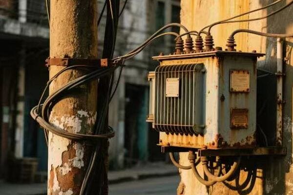
Diving into Maintenance and Troubleshooting Techniques
Let’s break down the essential aspects of maintaining and troubleshooting pole transformers:
1. Regular Visual Inspections
Visual checks are your first line of defense:
- External Condition: Look for rust, dents, or leaks
- Bushing Integrity: Check for cracks or contamination
- Oil Levels: Ensure proper oil levels in sight glasses
I once caught a small oil leak during a routine inspection that could have led to a major failure if left unchecked.
2. Oil Testing and Analysis
Oil is crucial for insulation and cooling:
- Dielectric Strength Test: Checks oil’s insulating properties
- Dissolved Gas Analysis (DGA): Identifies potential internal issues
- Moisture Content: Excessive moisture can degrade insulation
3. Thermal Imaging
Heat can indicate problems:
- Regular Scans: Conduct thermal imaging annually or bi-annually
- Hotspot Identification: Look for unusual temperature patterns
- Connection Checks: Identify loose or high-resistance connections
4. Electrical Testing
Periodic electrical tests ensure optimal performance:
- Turns Ratio Test: Verifies transformer windings
- Insulation Resistance Test: Checks insulation integrity
- Power Factor Test: Assesses overall condition
5. Load Monitoring
Keep an eye on the transformer’s workload:
- Regular Load Checks: Ensure the transformer isn’t overloaded
- Peak Load Recording: Identify potential capacity issues
- Load Balancing: Adjust loads if necessary
Here’s a quick reference table for maintenance activities:
| Activity | Frequency | Tools/Equipment Needed |
|---|---|---|
| Visual Inspection | Monthly | Inspection checklist, camera |
| Oil Testing | Annually | Oil testing kit, sample bottles |
| Thermal Imaging | Bi-annually | Thermal imaging camera |
| Electrical Testing | Every 3-5 years | Transformer test set |
| Load Monitoring | Continuous | Load monitoring devices |
In my experience, proactive maintenance is key to transformer longevity. I remember a case where we implemented a comprehensive maintenance program for a utility company. Within two years, we saw a 40% reduction in unexpected transformer failures. The key was catching and addressing minor issues before they became major problems.
One often overlooked aspect of maintenance is the importance of keeping good records. I always insist on detailed documentation of all inspections, tests, and repairs. This historical data is invaluable for identifying trends and predicting potential issues. In one instance, our records helped us identify a batch of transformers with a common manufacturing defect, allowing us to address the issue proactively across multiple sites.
Troubleshooting skills are equally important. I recall a challenging case where a transformer was repeatedly tripping offline. Standard tests showed no obvious issues. It was only when we conducted a detailed harmonic analysis that we discovered the problem – harmonic distortion from a nearby industrial facility was causing the transformer to overheat. By installing harmonic filters, we resolved the issue and improved overall power quality.
Here are some additional tips I’ve gathered over the years:
- Pay attention to environmental factors. Transformers in coastal or heavily polluted areas may need more frequent maintenance.
- Listen to the transformer. Unusual sounds can be early indicators of problems.
- Check for animal and vegetation intrusion. I’ve seen squirrels and vines cause significant damage.
- Be aware of the transformer’s age and history. Older units or those with a history of issues may need more frequent attention.
- Stay updated on manufacturer bulletins and recalls. Sometimes, systemic issues are identified after installation.
When troubleshooting, I always follow a systematic approach:
- Gather Information: Understand the symptoms and history
- Inspect Visually: Look for obvious signs of damage or wear
- Conduct Basic Tests: Start with simple, non-invasive tests
- Analyze Data: Look for patterns or anomalies in test results
- Formulate Hypotheses: Develop theories based on the data
- Test Hypotheses: Conduct targeted tests to confirm or rule out theories
- Implement Solutions: Address the root cause, not just symptoms
- Follow Up: Ensure the problem is fully resolved
Remember, effective maintenance and troubleshooting are about being proactive, thorough, and systematic. By staying vigilant and addressing issues promptly, you can significantly extend the life of pole transformers and ensure reliable power distribution.
Conclusion
Proper installation and maintenance of pole transformers are crucial for safe, efficient power distribution. From safety precautions to grounding techniques, each step requires attention to detail and expertise. Regular checks and proactive maintenance ensure longevity and reliability of these vital components.
Have you ever looked up at those gray cylinders on telephone poles and wondered what they do? These mysterious objects play a crucial role in powering our homes and businesses, yet many of us don’t know what they are.
A telephone pole transformer is a device that changes high-voltage electricity from power lines to a lower, safer voltage for use in homes and businesses. It’s a key part of the electrical grid, ensuring we have usable power in our buildings.
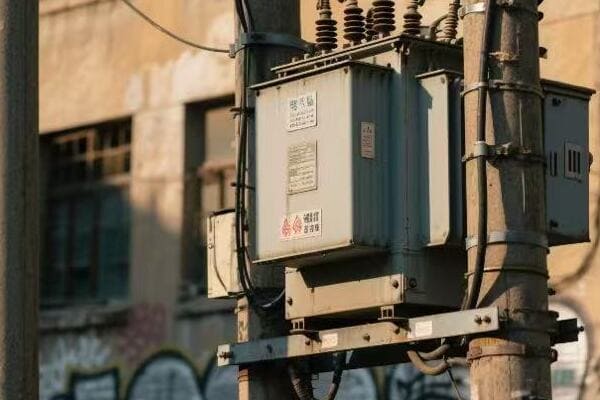
In this article, I’ll explain what these transformers do, how they work, and why they’re so important. Whether you’re a curious homeowner or someone interested in electrical systems, this guide will help you understand these vital components of our power infrastructure.
The Basics of Pole-Mounted Transformers: Function and Importance in Power Distribution?
Have you ever wondered why we need those bulky cylinders on telephone poles? They’re not just for show – these transformers are the unsung heroes of our power grid, working tirelessly to keep our lights on and our devices running.
Pole-mounted transformers are crucial in power distribution. They step down high voltage electricity from transmission lines to a lower, safer voltage for use in homes and businesses. These devices act as a bridge between the power grid and end-users, ensuring efficient and safe electricity delivery.
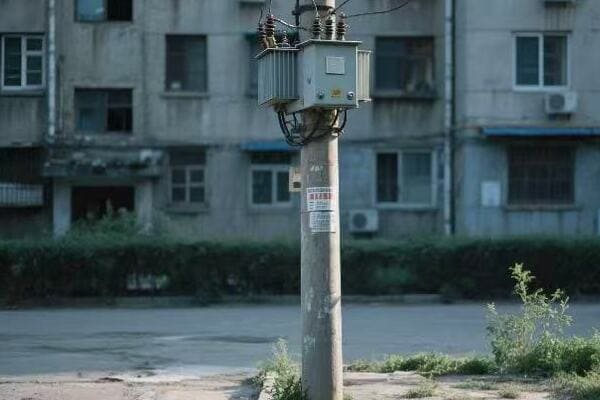
Understanding the Role of Pole-Mounted Transformers
To truly appreciate the importance of pole-mounted transformers, we need to break down their functions and significance:
1. Voltage Step-Down
The primary job of these transformers is to reduce the voltage of electricity. Power plants generate electricity at very high voltages, often between 155,000 to 765,000 volts. This high voltage is great for long-distance transmission but is far too dangerous for home use. Pole-mounted transformers step this voltage down to a usable level, typically 120/240 volts for homes in the United States.
2. Power Distribution
These transformers are key points in the distribution network. They take the electricity from main power lines and distribute it to individual buildings in a neighborhood. Without them, we’d need much more complex and expensive systems to get power from transmission lines to our homes.
3. Electrical Isolation
Transformers provide electrical isolation between the high-voltage system and consumer premises. This isolation is a crucial safety feature, protecting our homes from dangerous power surges and faults in the main grid.
4. Load Management
Transformers help manage the electrical load in different areas. Utility companies can adjust transformer settings to handle varying power demands in different neighborhoods or at different times of day.
Here’s a simple breakdown of the voltage transformation process:
| Stage | Voltage Level | Location |
|---|---|---|
| Generation | 155,000 – 765,000 V | Power Plant |
| Transmission | 155,000 – 765,000 V | Long-distance Power Lines |
| Sub-transmission | 69,000 – 138,000 V | Regional Distribution |
| Distribution | 4,000 – 34,500 V | Local Power Lines |
| End-User | 120/240 V | Homes and Businesses |
In my years working with electrical systems, I’ve seen firsthand how crucial these transformers are. I remember a project where we were upgrading the power supply for a growing suburban area. The existing transformers were overloaded, causing frequent power outages. By installing new, higher-capacity transformers, we were able to stabilize the power supply and accommodate the increased demand from new homes and businesses.
The importance of pole-mounted transformers goes beyond just delivering power. They’re a key part of making our electrical grid resilient and adaptable. As our energy needs change with the growth of electric vehicles and smart home technologies, these transformers will play an even more critical role in managing our power distribution.
Anatomy of a Telephone Pole Transformer: Key Components and How They Work?
Have you ever wondered what’s inside those mysterious cylinders on telephone poles? Let’s take a look at the inner workings of these essential devices that bring power to our homes and businesses.
A telephone pole transformer consists of several key components: a core made of laminated steel sheets, primary and secondary windings of insulated wire, insulating oil for cooling, and a protective tank. These parts work together to step down high voltage electricity to usable levels.
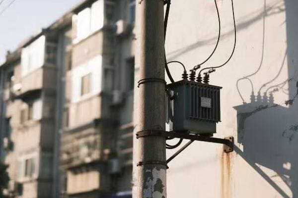
Breaking Down the Components of a Pole Transformer
Let’s dive deeper into the main parts of a pole transformer and how they function:
1. The Core
The core is the heart of the transformer. It’s made of thin, laminated sheets of silicon steel. These sheets are stacked together to form a rectangular or circular shape.
- Purpose: The core provides a path for the magnetic field that transfers energy between the primary and secondary windings.
- Why it matters: The laminated design reduces energy losses, making the transformer more efficient.
2. Windings
Transformers have two sets of windings: primary and secondary. These are coils of insulated copper or aluminum wire wrapped around the core.
- Primary Winding: Connected to the incoming high-voltage power lines.
- Secondary Winding: Delivers the stepped-down voltage to the distribution lines.
- How they work: The primary winding creates a magnetic field in the core, which then induces a voltage in the secondary winding.
3. Insulating Oil
The transformer tank is filled with a special type of oil.
- Purpose: The oil serves two main functions:
- Cooling: It absorbs heat from the core and windings.
- Insulation: It provides electrical insulation between components.
- Why it matters: Proper cooling and insulation are crucial for the transformer’s efficiency and lifespan.
4. Tank and Bushings
The tank houses all the internal components, while bushings are the connection points for the electrical wires.
- Tank: Usually made of steel, it protects the internal parts from the environment.
- Bushings: Insulated passages that allow electrical connections to enter and exit the tank safely.
Here’s a table summarizing the key components and their functions:
| Component | Function | Importance |
|---|---|---|
| Core | Provides path for magnetic flux | Enables energy transfer |
| Primary Winding | Receives high voltage | Input for transformation |
| Secondary Winding | Delivers low voltage | Output for consumer use |
| Insulating Oil | Cooling and insulation | Prevents overheating and breakdown |
| Tank | Protection | Shields internal components |
| Bushings | Electrical connections | Allows safe power transfer |
In my experience working with these transformers, I’ve always been amazed at how such a seemingly simple device can perform such a crucial function. I remember a time when we were troubleshooting a faulty transformer. By understanding each component’s role, we were able to pinpoint the issue to a problem with the insulating oil. It had degraded over time, reducing its cooling efficiency. Replacing the oil restored the transformer’s performance and prevented a potential failure.
The design of pole transformers is a testament to the ingenuity of electrical engineering. Each component plays a vital role in ensuring that we have safe, reliable power in our homes and businesses. As technology advances, we’re seeing innovations in materials and designs that make these transformers even more efficient and durable.
From High to Low: How Pole Transformers Step Down Voltage for Home Use?
Have you ever wondered how the incredibly high voltage in power lines becomes the safe, usable electricity in our homes? The answer lies in the fascinating process that occurs within pole transformers.
Pole transformers step down voltage through electromagnetic induction. The high voltage in the primary winding creates a magnetic field in the core, which then induces a lower voltage in the secondary winding. This process reduces the voltage from thousands to hundreds of volts for safe home use.
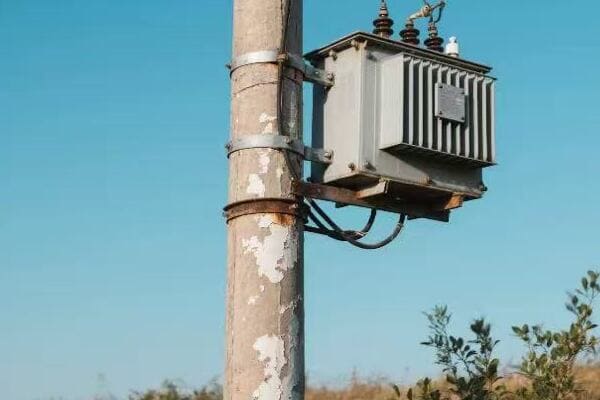
The Step-Down Process Explained
Let’s break down this complex process into simpler steps:
1. Input Stage
- High voltage electricity (typically 7,200 to 14,400 volts) enters the transformer.
- This electricity flows through the primary winding.
2. Magnetic Field Generation
- The current in the primary winding creates a changing magnetic field.
- This field is concentrated in the transformer’s steel core.
3. Induction
- The changing magnetic field induces a voltage in the secondary winding.
- The number of turns in the secondary winding is fewer than in the primary.
4. Voltage Reduction
- Due to the difference in winding turns, the voltage is reduced.
- Typically, it’s stepped down to 120/240 volts for residential use.
5. Output Stage
- The lower voltage electricity exits the transformer.
- It’s now safe for use in homes and businesses.
The relationship between the number of turns in the windings and the voltage is key to understanding how transformers work. Here’s a simplified formula:Vp / Vs = Np / Ns
Where:
- Vp = Primary voltage
- Vs = Secondary voltage
- Np = Number of turns in primary winding
- Ns = Number of turns in secondary winding
Let’s look at a practical example:
| Aspect | Primary Side | Secondary Side |
|---|---|---|
| Voltage | 7,200 V | 240 V |
| Number of Turns | 1,000 | 33 |
In this example, the primary winding has 1,000 turns and the secondary has 33 turns. This 30:1 ratio results in the voltage being stepped down from 7,200 V to 240 V.
I remember working on a project where we needed to upgrade the transformers in an older neighborhood. The existing transformers were struggling to handle the increased power demands from modern appliances and electric vehicles. By installing new transformers with optimized turn ratios, we were able to provide more stable voltage to the homes, reducing complaints about flickering lights and appliance issues.
The step-down process in pole transformers is a perfect example of how understanding and harnessing natural principles can lead to practical solutions. It’s amazing to think that this relatively simple concept of electromagnetic induction, discovered by Michael Faraday in 1831, is still the foundation of our modern power distribution system.
The efficiency of this process is crucial. While no transformer is 100% efficient, modern designs can achieve efficiencies of up to 98-99%. The small losses are mainly due to heat generated in the windings and core. That’s why proper cooling, usually through the insulating oil we discussed earlier, is so important.
As we move towards a future with more distributed energy resources, like solar panels and wind turbines, the role of transformers may evolve. We might see more bi-directional transformers that can handle power flowing both to and from homes. But the basic principle of stepping voltage up or down will remain a cornerstone of our electrical systems.
Types and Applications: Different Pole-Mounted Transformers in Electrical Systems?
When you look at telephone poles, you might think all those transformers look the same. But did you know there are actually different types, each designed for specific needs? Let’s explore the variety of pole-mounted transformers and their unique applications.
Pole-mounted transformers come in various types, including single-phase, three-phase, and autotransformers. Each type is designed for specific voltage requirements and applications, ranging from powering residential areas to supporting industrial operations and specialized electrical systems.
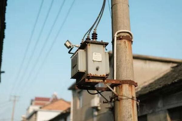
Exploring Transformer Types and Their Uses
Let’s dive into the main types of pole-mounted transformers and their applications:
1. Single-Phase Transformers
- Most common in residential areas
- Used for powering homes and small businesses
- Typically step down voltage from 7,200V to 120/240V
- Ideal for areas with lower power demands
2. Three-Phase Transformers
- Used in commercial and industrial settings
- Can handle higher loads and provide more efficient power distribution
- Often used in manufacturing plants, large office buildings, and shopping centers
- Step down voltage from higher levels (e.g., 12,470V) to usable levels (e.g., 480V)
3. Autotransformers
- Used for smaller voltage changes
- More efficient for certain applications
- Often used in power distribution systems for voltage regulation
- Can be used to boost voltage in long-distance power lines
4. Pad-Mounted Transformers
- Ground-level alternative to pole-mounted transformers
- Used in underground power distribution systems
- Common in newer residential developments and urban areas
- Offer improved aesthetics and protection from weather
Here’s a comparison table to help understand the differences:
| Type | Voltage Range | Main Applications | Advantages |
|---|---|---|---|
| Single-Phase | 7,200V to 120/240V | Residential areas | Simple, cost-effective |
| Three-Phase | 12,470V to 480V | Commercial, industrial | Higher efficiency, greater power capacity |
| Autotransformer | Various | Voltage regulation | Compact, economical for small voltage changes |
| Pad-Mounted | Similar to pole-mounted | Underground systems | Aesthetically pleasing, weather-protected |
In my experience, choosing the right type of transformer is crucial for efficient power distribution. I once worked on a project for a new industrial park where we needed to decide between multiple single-phase transformers or fewer three-phase units. We opted for three-phase transformers due to the high power demands of the manufacturing equipment. This choice not only provided more efficient power distribution but also saved space and reduced maintenance needs.
The choice of transformer type often depends on several factors:
- Load Requirements: The amount and type of power needed by the end-users.
- Existing Infrastructure: Whether the area already has single-phase or three-phase power lines.
- Future Growth: Anticipating increased power needs in the future.
- Environmental Factors: Considerations like weather conditions or aesthetic requirements.
For example, in a growing suburban area, we might start with single-phase transformers for residential use. But if there are plans for future commercial development, it might be wise to install three-phase transformers in certain locations to accommodate future needs.
Autotransformers, while less common in residential settings, play a crucial role in power transmission. I’ve seen them used effectively in substations to adjust voltage levels between different parts of the grid. Their efficiency in making small voltage adjustments makes them valuable for maintaining consistent voltage across long-distance power lines.
The trend towards underground power distribution in many urban and suburban areas has led to an increase in the use of pad-mounted transformers. These units offer the same functionality as pole-mounted transformers but with improved aesthetics and protection from the elements. In a recent project in a new residential development, we used pad-mounted transformers exclusively. The homeowners appreciated the unobstructed views, and the utility company found maintenance easier and safer.
As we move towards smarter, more flexible power grids, the role of transformers is evolving. We’re seeing the development of smart transformers that can communicate with the grid, adjust to changing loads, and even help integrate renewable energy sources. These advancements are making our power distribution systems more efficient and resilient.
Safety and Maintenance: Caring for Telephone Pole Transformers in Your Neighborhood?
Have you ever wondered about the safety of those transformers hanging on poles in your neighborhood? Or maybe you’re curious about how they’re maintained? Let’s explore the important aspects of safety and maintenance for these crucial devices.
Safety around pole transformers involves respecting clearances, reporting issues, and avoiding contact. Maintenance includes regular inspections, oil testing, and repairs by trained professionals. Proper care ensures reliable power distribution and prevents hazards in your neighborhood.
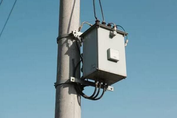
Safety First: Protecting Your Community
When it comes to pole transformers, safety is paramount. Here are key safety considerations:
1. Clearance Zones
- Keep a safe distance from transformers
- Never climb poles or tamper with equipment
- Maintain required clearances when planting trees or building structures
2. Reporting Issues
- Contact your utility company if you notice:
- Unusual noises
- Oil leaks
- Physical damage to the transformer
- Don’t attempt to fix issues yourself
3. Emergency Situations
- In case of fire or severe damage, call emergency services immediately
- Keep others away from the area
Maintenance: Keeping the Power Flowing
Regular maintenance is crucial for the longevity and efficiency of pole transformers. Here’s what typically happens:
1. Routine Inspections
- Visual checks for damage or wear
- Thermal imaging to detect hot spots
- Check for oil leaks or corrosion
2. Oil Testing and Replacement
- Regular sampling and testing of transformer oil
- Oil replacement if contaminated or degraded
3. Load Management
- Monitoring transformer load to prevent overheating
- Adjusting connections if needed
4. Repairs and Replacements
- Addressing issues promptly to prevent failures
- Replacing old or damaged transformers
Here’s a table summarizing key maintenance tasks and their frequency:
| Maintenance Task | Frequency | Importance |
|---|---|---|
| Visual Inspection | Monthly | Detect visible issues early |
| Oil Testing | Annually | Ensure proper insulation and cooling |
| Thermal Imaging | Quarterly | Identify potential overheating |
| Load Assessment | Ongoing | Prevent overloading and extend lifespan |
In my years of experience with electrical systems, I’ve seen how proper maintenance can prevent major issues. I remember a case where routine oil testing revealed contamination in a transformer. By addressing this early, we avoided a potential failure that could have left an entire neighborhood without power for days.
For homeowners and community members, the best way to contribute to transformer safety and maintenance is to be observant and report any concerns to your utility company. Your awareness can help prevent accidents and ensure a reliable power supply for everyone.
The Impact of Weather on Transformer Maintenance
Weather plays a significant role in transformer maintenance. Different climates present unique challenges:
Hot Climates
- Increased risk of overheating
- More frequent oil checks and cooling system inspections
- Possible need for additional cooling measures
Cold Climates
- Risk of oil freezing in extreme cold
- Checks for ice buildup on external components
- Ensuring proper insulation against temperature fluctuations
Coastal Areas
- Higher risk of corrosion due to salt air
- More frequent checks for rust and deterioration
- Special coatings may be needed for protection
Storm-Prone Regions
- Regular checks for damage from high winds or lightning
- Ensuring proper grounding and surge protection
- Possible need for reinforced mounting or additional guy wires
I once worked in a coastal area where the salt air was causing rapid corrosion of transformer components. We implemented a program of more frequent inspections and started using specially coated hardware. This proactive approach significantly extended the life of the transformers and reduced unexpected outages.
The Role of Technology in Transformer Maintenance
Advancements in technology are changing how we maintain transformers:
-
Smart Sensors: These can continuously monitor transformer health, alerting maintenance teams to potential issues before they become serious problems.
-
Drones: Used for visual inspections of hard-to-reach transformers, reducing the need for workers to climb poles.
-
AI and Machine Learning: These technologies can analyze data from transformers to predict when maintenance will be needed, allowing for more efficient scheduling of repairs.
-
Mobile Apps: Utility workers can now access transformer data and maintenance history in real-time, improving the speed and accuracy of their work.
In a recent project, we implemented a system of smart sensors on a group of transformers in a rural area. The real-time data allowed us to detect and address issues much faster than our previous schedule of periodic manual inspections. This not only improved reliability but also reduced maintenance costs over time.
Community Involvement in Transformer Safety
While maintenance is primarily the responsibility of utility companies, community involvement can play a crucial role in transformer safety:
-
Education: Understanding the basics of transformer safety can help residents avoid risks and recognize potential problems.
-
Reporting: Encouraging community members to report any unusual sights or sounds near transformers can lead to early detection of issues.
-
Landscaping: Proper tree trimming and landscaping around transformers can prevent interference and make maintenance easier.
-
Emergency Preparedness: Communities can develop plans for extended power outages in case of transformer failures.
I’ve seen the positive impact of community involvement firsthand. In one neighborhood, after we conducted a safety awareness campaign, reports of potential transformer issues increased significantly. This led to several preventive maintenance actions that likely avoided future outages.
Looking to the Future of Transformer Maintenance
As our power grids evolve, so too will our approach to transformer maintenance:
-
Predictive Maintenance: Moving from scheduled maintenance to predictive maintenance based on real-time data.
-
Eco-Friendly Materials: Development of more environmentally friendly insulating oils and materials.
-
Integration with Smart Grids: Transformers becoming active, communicative parts of smart grid systems.
-
Remote Diagnostics: Increased ability to diagnose and even solve some issues remotely, reducing the need for field visits.
The field of transformer maintenance is constantly evolving, and staying updated with these changes is crucial for ensuring the reliability and safety of our power distribution systems.
Conclusion
Telephone pole transformers are vital components of our power distribution system. They step down high voltage to safe levels for home use, come in various types for different applications, and require regular maintenance for safe, efficient operation. Understanding these devices helps us appreciate the complexity of our power infrastructure.
Are you confused about which type of pole transformer is best for your electrical grid? You’re not alone. Many people find it challenging to choose the right transformer for their specific needs.
Choosing the right pole transformer depends on your grid’s voltage requirements, load capacity, and specific application. Options include single-phase, three-phase, conventional, smart, step-up, step-down, and specialized transformers like autotransformers and padmounts. Each type serves different purposes in power distribution systems.
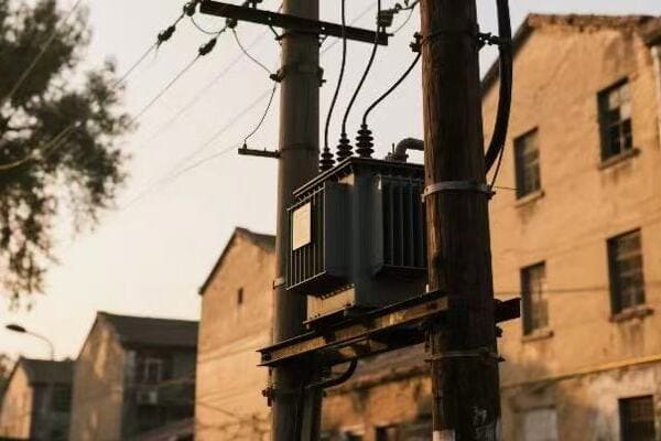
In this article, I’ll guide you through the different types of pole transformers. We’ll explore their features, applications, and how to select the best one for your needs. Let’s dive in and demystify the world of pole transformers together.
Single-Phase vs. Three-Phase Pole Transformers: Understanding the Basics and Applications?
Have you ever wondered why some areas have different types of transformers? The choice between single-phase and three-phase transformers can significantly impact power distribution efficiency and reliability.
Single-phase transformers are typically used in residential areas with lower power demands. Three-phase transformers are more common in industrial and commercial settings where higher power capacity is needed. The choice depends on the load requirements and the existing power infrastructure.
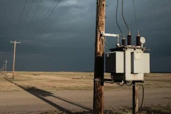
Diving Deeper into Single-Phase and Three-Phase Transformers
Let’s break down the key differences and applications of these two transformer types:
Single-Phase Transformers
-
Basic Structure
- Two windings: primary and secondary
- Simpler design compared to three-phase
-
Applications
- Residential areas
- Rural power distribution
- Small businesses with low power needs
-
Advantages
- Cost-effective for low power requirements
- Easier to install and maintain
- Suitable for areas with unbalanced loads
Three-Phase Transformers
-
Basic Structure
- Three sets of windings
- More complex design
-
Applications
- Industrial facilities
- Large commercial buildings
- Urban power distribution
-
Advantages
- Higher efficiency in power transmission
- Better suited for heavy machinery and equipment
- More stable power supply for large loads
Comparing Single-Phase and Three-Phase Transformers
Here’s a comparison table to help you understand the differences:
| Feature | Single-Phase | Three-Phase |
|---|---|---|
| Power Capacity | Lower | Higher |
| Efficiency | Good for small loads | Better for large loads |
| Cost | Lower initial cost | Higher initial cost, but more efficient long-term |
| Size | Smaller | Larger |
| Typical Voltage | 120/240V | 208/120V or 480/277V |
| Load Balancing | Not applicable | Required for optimal performance |
In my experience, choosing between single-phase and three-phase transformers often comes down to the specific needs of the area. I once worked on a project in a small rural town where we opted for single-phase transformers. The lower power demands and scattered population made it the most cost-effective solution. However, when I was involved in upgrading the power supply for a new industrial park, we went with three-phase transformers to handle the high power requirements of the manufacturing equipment.
The key is to assess your current and future power needs carefully. If you’re in a residential area with no plans for significant industrial development, single-phase transformers are likely your best bet. But if you’re in a rapidly growing area or one with industrial aspirations, investing in three-phase infrastructure could save you money and headaches in the long run.
Conventional and Smart Pole Transformers: Comparing Features for Modern Grid Needs?
Are you still relying on conventional transformers, or have you considered upgrading to smart ones? The choice between conventional and smart pole transformers can significantly impact your grid’s efficiency and reliability.
Conventional pole transformers are traditional, reliable, and cost-effective for basic power distribution. Smart transformers offer advanced features like real-time monitoring, automatic voltage regulation, and data communication capabilities, making them ideal for modern, responsive grid systems.
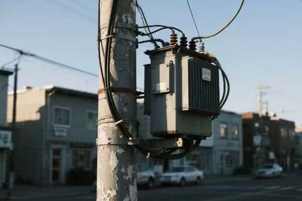
Exploring the World of Conventional and Smart Transformers
Let’s delve into the features and benefits of both types:
Conventional Transformers
-
Basic Features
- Simple design focused on voltage transformation
- Passive operation without monitoring capabilities
- Reliable and time-tested technology
-
Advantages
- Lower initial cost
- Less complex, easier to maintain
- Suitable for areas with stable power demands
-
Limitations
- No real-time monitoring or data collection
- Manual intervention required for adjustments
- Limited adaptability to changing grid conditions
Smart Transformers
-
Advanced Features
- Real-time monitoring and data collection
- Automatic voltage regulation
- Remote control and communication capabilities
- Integration with smart grid systems
-
Advantages
- Improved grid efficiency and reliability
- Faster response to power quality issues
- Better load management and forecasting
- Enhanced integration of renewable energy sources
-
Considerations
- Higher initial cost
- More complex, requiring specialized maintenance
- Cybersecurity considerations
Comparing Conventional and Smart Transformers
Here’s a detailed comparison to help you understand the differences:
| Feature | Conventional Transformers | Smart Transformers |
|---|---|---|
| Monitoring | Manual inspections | Real-time, continuous |
| Data Collection | Limited, manual | Extensive, automated |
| Voltage Regulation | Fixed or manual tap changing | Automatic, dynamic |
| Communication | None | Two-way with control center |
| Fault Detection | Reactive, after occurrence | Proactive, predictive |
| Integration with Renewables | Limited | Advanced, with load balancing |
| Initial Cost | Lower | Higher |
| Maintenance | Simpler, less frequent | More complex, but potentially less frequent |
| Lifespan | Typically longer | Potentially shorter due to electronic components |
In my career, I’ve worked with both conventional and smart transformers. I remember a project where we upgraded a suburban area from conventional to smart transformers. Initially, there was hesitation due to the higher costs. However, within a year, we saw significant improvements in power quality and reduced outage times. The ability to detect and respond to issues before they escalated was a game-changer.
That said, smart transformers aren’t always the best choice. In remote areas with limited communication infrastructure, the advanced features of smart transformers might not be fully utilized. In such cases, the reliability and simplicity of conventional transformers can be more appropriate.
The decision between conventional and smart transformers should be based on your specific grid needs, future growth plans, and budget constraints. Smart transformers shine in areas with fluctuating loads, high renewable energy integration, or where power quality is a major concern. Conventional transformers remain a solid choice for stable, predictable power needs where advanced monitoring isn’t critical.
Step-Up and Step-Down Pole Transformers: Choosing the Right Voltage Transformation?
Are you struggling to decide between step-up and step-down transformers for your power distribution needs? This choice is crucial for ensuring efficient and safe power transmission across different parts of the grid.
Step-up transformers increase voltage for efficient long-distance transmission, while step-down transformers reduce voltage for safe local distribution and consumption. The choice depends on where the transformer is placed in the power distribution chain and the voltage requirements of the connected systems.
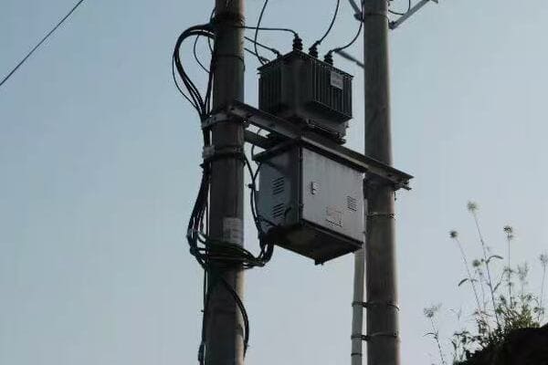
Understanding Step-Up and Step-Down Transformers
Let’s explore the characteristics and applications of both types:
Step-Up Transformers
-
Function
- Increase voltage from generation level to transmission level
- Typically used at power plants
-
Advantages
- Reduces power loss over long distances
- Allows for more efficient power transmission
-
Applications
- Power plants to transmission lines
- Renewable energy sources to grid connection
Step-Down Transformers
-
Function
- Decrease voltage from transmission level to distribution level
- Further step down voltage for end-user consumption
-
Advantages
- Makes high voltage power safe for local use
- Allows for proper voltage levels in homes and businesses
-
Applications
- Substations to local distribution
- Pole-mounted transformers in neighborhoods
Comparing Step-Up and Step-Down Transformers
Here’s a detailed comparison to help you understand the differences:
| Feature | Step-Up Transformers | Step-Down Transformers |
|---|---|---|
| Primary Function | Increase voltage | Decrease voltage |
| Typical Location | Power generation sites | Distribution points, neighborhoods |
| Winding Ratio | Secondary > Primary | Primary > Secondary |
| Current Change | Decreases current | Increases current |
| Power Loss Mitigation | Reduces transmission losses | N/A |
| Safety Considerations | Handles very high voltages | Makes power safe for end-use |
| Size | Generally larger | Varies, often smaller in distribution |
In my experience, the choice between step-up and step-down transformers is often dictated by the transformer’s position in the power distribution chain. I once worked on a project for a new solar farm where we needed step-up transformers to connect the generated power to the main grid. The farm produced power at around 400V, but we needed to step it up to 69kV for efficient transmission to the nearby substation.
On the other hand, in urban development projects, I’ve frequently used step-down transformers. In one case, we were setting up a new residential area. We had to step down the voltage from the 13.8kV distribution lines to 120/240V for household use. This required careful planning to ensure we had the right number and capacity of transformers to meet the neighborhood’s power demands.
The key to choosing between step-up and step-down transformers lies in understanding your power system’s structure and requirements. Here are some considerations:
- Voltage Requirements: Assess the input voltage and the required output voltage.
- Power Source: Are you connecting a generation source to the grid or distributing power to end-users?
- Distance: For long-distance transmission, step-up transformers are crucial to minimize power losses.
- Safety: In areas close to end-users, step-down transformers are essential for providing safe, usable voltage levels.
Remember, in many cases, you’ll need both types at different points in your power system. A well-designed power distribution network often incorporates a series of step-up and step-down transformers to efficiently move electricity from generation to consumption.
Specialized Pole Transformers: Autotransformers, Padmounts, and Their Unique Uses?
Have you encountered situations where standard transformers just don’t cut it? Specialized transformers like autotransformers and padmounts offer unique solutions for specific power distribution challenges.
Autotransformers are efficient for small voltage changes and can be more compact than traditional transformers. Padmount transformers are ground-mounted units ideal for underground distribution systems. These specialized types offer tailored solutions for unique power distribution needs in various settings.
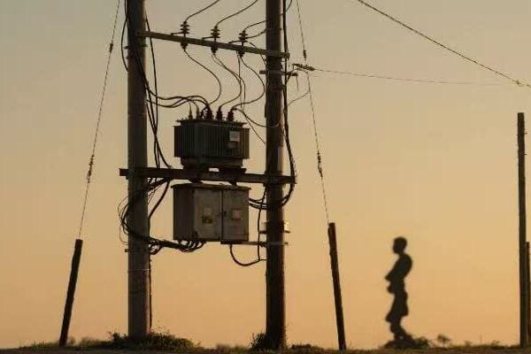
Diving into Specialized Transformer Types
Let’s explore the characteristics and applications of these specialized transformers:
Autotransformers
-
Basic Structure
- Single winding acts as both primary and secondary
- Portion of the winding is shared between input and output
-
Advantages
- More efficient for small voltage changes
- Smaller and lighter than two-winding transformers
- Lower cost for same power rating
-
Applications
- Voltage regulation in distribution systems
- Interconnecting systems with slightly different voltages
- Motor starting applications
Padmount Transformers
-
Basic Structure
- Ground-mounted, enclosed in a steel cabinet
- Can be single-phase or three-phase
-
Advantages
- Aesthetically pleasing, suitable for residential areas
- Safer due to locked enclosure
- Ideal for underground distribution systems
-
Applications
- Urban and suburban power distribution
- Commercial and industrial parks
- Areas where overhead lines are not feasible or desired
Comparing Autotransformers and Padmount Transformers
Here’s a detailed comparison to help you understand these specialized types:
| Feature | Autotransformers | Padmount Transformers |
|---|---|---|
| Primary Use | Voltage adjustment | Distribution in underground systems |
| Size | Compact | Larger, ground-mounted |
| Efficiency | High for small voltage changes | Similar to standard transformers |
| Cost | Lower for same power rating | Higher due to enclosure and features |
| Safety | Less isolation between circuits | Enhanced safety with locked enclosure |
| Aesthetics | Similar to standard transformers | More visually appealing |
| Installation | Can be pole-mounted or pad-mounted | Ground-mounted only |
| Maintenance | Generally simpler | May require specialized access |
In my career, I’ve encountered numerous situations where these specialized transformers proved invaluable. I remember a project in a historic district where overhead lines were prohibited. We used padmount transformers to create an underground distribution system that preserved the area’s aesthetic while providing reliable power.
Another interesting case involved an industrial facility that needed to interconnect two systems with a small voltage difference. An autotransformer was the perfect solution, offering efficient voltage adjustment without the need for a full-sized traditional transformer.
When considering these specialized transformers, keep in mind:
- Voltage Change Requirements: Autotransformers are ideal for small voltage adjustments, typically up to 20%.
- Space Constraints: In areas with limited space, autotransformers can be a compact solution.
- Aesthetic Concerns: Padmount transformers are excellent for areas where visual impact is a concern.
- Underground Systems: If you’re designing an underground distribution system, padmount transformers are often the go-to choice.
- Safety Needs: In areas with high foot traffic or public access, the locked enclosures of padmount transformers offer added safety.
Remember, while these specialized transformers offer unique benefits, they also come with their own set of considerations. Autotransformers, for instance, provide less electrical isolation between primary and secondary circuits, which may be a concern in some applications. Padmount transformers, while visually appealing and safe, can be more expensive and may require special equipment for installation and maintenance.
Environmental Considerations: Selecting Pole Transformers for Different Climate Zones?
Have you ever wondered why the same transformer might perform differently in different parts of the world? The impact of environmental factors on transformer performance is often underestimated, but it’s crucial for ensuring reliability and longevity.
Selecting the right pole transformer for different climate zones involves considering factors like temperature extremes, humidity, altitude, and pollution levels. Transformers must be designed to withstand local environmental challenges to ensure optimal performance and longevity in diverse climatic conditions.
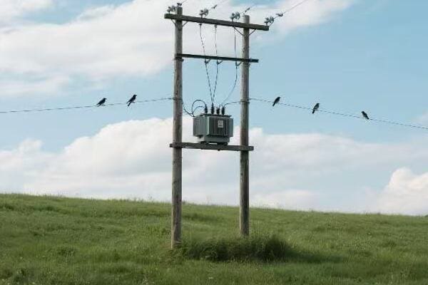
Adapting Transformers to Various Climate Zones
Let’s explore how different climate factors affect transformer selection and design:
Hot and Humid Climates
-
Challenges
- High ambient temperatures
- Increased risk of overheating
- Accelerated insulation degradation
-
Solutions
- Enhanced cooling systems (e.g., forced oil circulation)
- Use of heat-resistant materials
- Dehumidifiers to control moisture
-
Examples
- Tropical regions, Middle East
Cold Climates
-
Challenges
- Extremely low temperatures
- Risk of oil freezing
- Thermal cycling stress
-
Solutions
- Low-temperature grade insulating oils
- Heaters for extreme cold conditions
- Reinforced tank designs for thermal expansion
-
Examples
- Arctic regions, high-altitude areas
Coastal and High-Pollution Areas
-
Challenges
- Salt spray corrosion
- Industrial pollution
- Increased risk of insulator flashover
-
Solutions
- Corrosion-resistant materials and coatings
- Specially designed insulators (e.g., silicone rubber)
- More frequent maintenance schedules
-
Examples
- Coastal industrial zones, heavily polluted urban areas
High-Altitude Regions
-
Challenges
- Reduced air density affecting cooling
- Increased risk of corona discharge
- Lower dielectric strength of air
-
Solutions
- Adjusted cooling calculations
- Enhanced insulation systems
- Special bushing designs
-
Examples
- Mountain regions, high-plateau areas
Comparing Transformer Designs for Different Climates
Here’s a comparison table of transformer features for various climate zones:
| Feature | Hot & Humid | Cold Climate | Coastal/High-Pollution | High-Altitude |
|---|---|---|---|---|
| Cooling System | Enhanced, often forced | Standard, with heating options | Standard, with corrosion protection | Adjusted for lower air density |
| Insulating Oil | High temperature grade | Low temperature grade | Standard, with moisture resistance | Standard, with adjusted volume |
| Tank Design | Extra corrosion protection | Reinforced for thermal cycling | Heavy-duty corrosion protection | Standard, with pressure considerations |
| Bushings | Extended creepage | Cold-resistant materials | Pollution-resistant (e.g., silicone) | Corona-resistant design |
| Maintenance Frequency | Higher | Standard | Higher | Standard, with specific checks |
In my years of experience, I’ve encountered numerous challenges related to climate-specific transformer design. I recall a project in a tropical coastal area where we faced a perfect storm of high heat, humidity, and salt spray. We had to completely rethink our standard transformer design.
We ended up using a combination of forced oil cooling, corrosion-resistant stainless steel tanks, and silicone rubber insulators. The initial cost was higher, but the long-term savings in maintenance and increased reliability made it worthwhile. The client was initially skeptical about the custom design, but after two years of operation with zero weather-related issues, they were fully convinced.
When selecting transformers for different climate zones, consider these key points:
- Temperature Range: Understand the full range of temperatures the transformer will face, not just averages.
- Humidity and Precipitation: High humidity can lead to condensation inside the transformer, while heavy rain or snow can stress the outer components.
- Altitude: For every 100m above 1000m, you generally need to derate the transformer by about 0.4%.
- Pollution Levels: In areas with high industrial pollution or coastal salt spray, consider the Pollution Severity Index when selecting insulation.
- Wind and Seismic Activity: In areas prone to high winds or earthquakes, mechanical strength becomes a crucial factor.
- Local Regulations: Some regions have specific requirements for transformer design and installation based on their environmental conditions.
Remember, a transformer that works perfectly in one climate might fail prematurely in another. It’s not just about making the transformer work; it’s about ensuring it works efficiently and reliably for its entire expected lifespan. Sometimes, investing in a more robust design upfront can lead to significant savings in maintenance and replacement costs down the line.
In one interesting case, we were tasked with designing transformers for a mining operation in a high-altitude desert environment. We faced the dual challenge of thin air affecting cooling and extreme temperature swings between day and night. Our solution involved a custom cooling system designed for the lower air density and special insulating oil that could handle the temperature fluctuations without degrading. It was a complex project, but it taught me the importance of considering multiple environmental factors simultaneously.
The key takeaway is that there’s no one-size-fits-all solution when it comes to transformer design for different climate zones. Each environment presents its unique set of challenges, and the best approach is often a customized design that takes all local factors into account. As engineers and designers, it’s our job to understand these nuances and create solutions that ensure reliable power distribution, regardless of the environmental challenges.
Conclusion
Choosing the right pole transformer is crucial for efficient and reliable power distribution. Consider factors like phase requirements, smart capabilities, voltage needs, specialized applications, and environmental conditions. Each type has its strengths, and the best choice depends on your specific grid needs and local climate.
