Are you confused about the different types of dry type transformers? You’re not alone. Many of my clients struggle to understand the options available for their power distribution needs.
Dry type transformers come in several types, including cast resin, vacuum pressure impregnated (VPI), open-wound, and encapsulated. Each type has unique features suited for different applications, from indoor installations to industrial settings. Understanding these types is crucial for choosing the right transformer for your project.
In my years of experience in the power industry, I’ve worked with all types of dry transformers. Let’s explore each type in detail to help you make an informed decision for your power distribution needs.
What are the main types of dry type transformers?
Have you ever wondered about the different types of dry transformers available? I often get this question from clients who are new to power distribution systems.
The main types of dry type transformers are cast resin, vacuum pressure impregnated (VPI), open-wound, and encapsulated. Each type has its own manufacturing process, characteristics, and ideal applications. The choice depends on factors like environment, load requirements, and budget.
Let’s dive deeper into each type of dry transformer. My experience with these different types will help you understand their unique features and applications.
Cast Resin Transformers
Cast resin transformers are a popular choice for many of my clients. Here’s why:
- Manufacturing Process: The windings are cast in epoxy resin under vacuum.
- Characteristics: Excellent moisture resistance, high mechanical strength.
- Applications: Ideal for harsh environments, marine applications, and areas with high humidity.
I once installed a cast resin transformer in a coastal industrial plant. Its resistance to moisture and salt air made it perfect for the challenging environment.
Vacuum Pressure Impregnated (VPI) Transformers
VPI transformers offer a good balance of performance and cost:
- Manufacturing Process: Windings are impregnated with varnish under vacuum and pressure.
- Characteristics: Good thermal properties, cost-effective.
- Applications: Suitable for most indoor industrial and commercial applications.
Open-Wound Transformers
These are the simplest type of dry transformers:
- Manufacturing Process: Windings are simply coated with varnish.
- Characteristics: Lightweight, good for low humidity environments.
- Applications: Used in some industrial settings where environmental protection is not a major concern.
Encapsulated Transformers
Encapsulated transformers offer enhanced protection:
- Manufacturing Process: Entire core and coil assembly is encapsulated in epoxy.
- Characteristics: Excellent protection against moisture and contaminants.
- Applications: Ideal for outdoor installations or very harsh environments.
| Type | Key Feature | Best For |
|---|---|---|
| Cast Resin | Moisture resistant | Harsh environments |
| VPI | Cost-effective | General indoor use |
| Open-Wound | Lightweight | Low humidity areas |
| Encapsulated | Fully protected | Outdoor/harsh conditions |
In my experience, understanding these types is crucial for selecting the right transformer for your specific needs. Each type has its strengths, and the best choice depends on your unique situation.
How do cast resin and VPI dry type transformers differ?
Clients often ask me about the differences between cast resin and VPI transformers. It’s a common dilemma when choosing a dry type transformer for their projects.
Cast resin transformers have windings encased in epoxy, offering superior moisture and contamination resistance. VPI transformers have windings impregnated with varnish, providing good performance at a lower cost. Cast resin is better for harsh environments, while VPI is suitable for most indoor applications.
Let’s explore the key differences between these two popular types of dry transformers. My experience with both types will help you understand their unique characteristics.
Manufacturing Process
The manufacturing process is a key differentiator:
-
Cast Resin:
- Windings are placed in a mold.
- Epoxy resin is poured and cured under vacuum.
- Results in a solid, void-free insulation.
-
VPI:
- Windings are wound with insulating material.
- Entire assembly is placed in a vacuum tank and impregnated with varnish.
- Process is repeated several times for thorough impregnation.
I once visited a transformer manufacturing plant. The precision required for the cast resin process was impressive, while the VPI process was more straightforward but still effective.
Environmental Resistance
Environmental factors often guide the choice between these types:
-
Cast Resin:
- Excellent resistance to moisture and contamination.
- Can withstand harsh environments, including outdoor installations.
- Suitable for high humidity areas.
-
VPI:
- Good resistance to normal indoor environmental conditions.
- Less suitable for very humid or contaminated environments.
- Typically used in controlled indoor settings.
Thermal Performance
Heat management is crucial for transformer longevity:
-
Cast Resin:
- Excellent heat dissipation due to solid insulation.
- Can handle higher temperature rises.
- Better short-circuit strength due to epoxy encapsulation.
-
VPI:
- Good thermal performance for most applications.
- May require additional cooling in high ambient temperature conditions.
- Slightly lower short-circuit strength compared to cast resin.
Cost Considerations
Budget often plays a role in the decision:
-
Cast Resin:
- Higher initial cost due to more complex manufacturing process.
- Lower maintenance costs over time.
- Longer lifespan can offset higher initial investment.
-
VPI:
- Lower initial cost.
- May require more frequent maintenance in challenging environments.
- Good value for standard indoor applications.
| Feature | Cast Resin | VPI |
|---|---|---|
| Moisture Resistance | Excellent | Good |
| Environmental Tolerance | High | Moderate |
| Initial Cost | Higher | Lower |
| Maintenance | Low | Moderate |
| Typical Applications | Harsh environments, outdoors | General indoor use |
In my experience, the choice between cast resin and VPI often comes down to the specific environmental conditions and budget constraints of the project. For critical applications in challenging environments, I usually recommend cast resin. For standard indoor applications where cost is a significant factor, VPI transformers often provide the best value.
Which dry type transformer is best for indoor applications?
When clients ask me about indoor transformer solutions, I often recommend dry type transformers. But which type is best? It’s a question I hear frequently.
For most indoor applications, Vacuum Pressure Impregnated (VPI) dry type transformers are the best choice. They offer a good balance of performance, cost-effectiveness, and safety. VPI transformers are suitable for various indoor settings, from commercial buildings to light industrial applications.
Let’s explore why VPI transformers are often the top choice for indoor use and when other types might be more suitable. My experience with various indoor installations will provide valuable insights.
Why VPI Transformers Excel Indoors
VPI transformers have several advantages for indoor use:
-
Cost-Effectiveness:
- Lower initial cost compared to cast resin transformers.
- Good performance for the price in controlled environments.
-
Safety:
- Fire-resistant design suitable for indoor spaces.
- No oil, reducing fire risk compared to liquid-filled transformers.
-
Maintenance:
- Relatively low maintenance requirements.
- Easy to inspect and clean in indoor settings.
I once installed a VPI transformer in a large office building. Its compact size and low maintenance needs made it perfect for the limited utility space available.
When to Consider Other Types
While VPI is often the best choice, there are situations where other types might be more suitable:
-
Cast Resin:
- Best for indoor areas with high humidity or contamination risk.
- Ideal for critical applications where reliability is paramount.
-
Open-Wound:
- Suitable for very dry, clean indoor environments.
- Can be a cost-effective option for specific industrial applications.
-
Encapsulated:
- Good for indoor areas exposed to unusual environmental stresses.
- Useful in manufacturing facilities with airborne contaminants.
Factors to Consider for Indoor Applications
When choosing a dry type transformer for indoor use, consider these factors:
-
Environment:
- Humidity levels
- Presence of contaminants
- Temperature fluctuations
-
Load Profile:
- Steady loads vs. variable loads
- Peak demand requirements
-
Space Constraints:
- Available floor space
- Ventilation requirements
-
Noise Considerations:
- Proximity to work areas
- Local noise regulations
-
Future Expansion:
- Potential for increased power needs
- Flexibility for system upgrades
| Factor | VPI | Cast Resin | Open-Wound |
|---|---|---|---|
| Cost | Moderate | High | Low |
| Humidity Resistance | Good | Excellent | Poor |
| Maintenance | Low | Very Low | Moderate |
| Noise Level | Low | Low | Moderate |
| Size | Compact | Larger | Most Compact |
In my experience, while VPI transformers are often the best all-around choice for indoor applications, the final decision should always be based on a thorough assessment of the specific installation environment and requirements. I always recommend a site visit and detailed load analysis before making a final recommendation.
Are open-wound dry type transformers suitable for industrial use?
I often get asked about open-wound transformers for industrial applications. It’s a topic that causes a lot of confusion among my clients in the manufacturing sector.
Open-wound dry type transformers can be suitable for some industrial uses, particularly in clean, dry environments with low humidity. They are cost-effective and efficient for certain applications. However, their lack of environmental protection limits their use in harsh industrial settings with moisture, dust, or chemical contaminants.
Let’s delve into the suitability of open-wound transformers for industrial use. My experience with various industrial installations will help clarify when these transformers are a good choice and when they’re not.
Advantages of Open-Wound Transformers in Industry
Open-wound transformers have some benefits for industrial use:
-
Cost-Effectiveness:
- Lower initial cost compared to other dry type transformers.
- Can be a budget-friendly option for suitable environments.
-
Efficiency:
- Good efficiency due to direct air cooling of windings.
- Can handle load variations well in appropriate conditions.
-
Size and Weight:
- Generally smaller and lighter than other types.
- Easier to install in space-constrained industrial settings.
I once installed an open-wound transformer in a small, climate-controlled manufacturing facility. Its compact size and lower cost made it an ideal choice for their limited budget and space.
Limitations in Industrial Settings
However, open-wound transformers have significant limitations:
-
Environmental Sensitivity:
- Vulnerable to moisture and dust.
- Not suitable for outdoor use or humid environments.
-
Contamination Risk:
- Exposed windings can accumulate dirt and debris.
- Potential for reduced lifespan in dirty industrial environments.
-
Safety Concerns:
- Less protected against accidental contact.
- May require additional safety measures in some industrial settings.
Suitable Industrial Applications
Open-wound transformers can be appropriate for:
-
Clean Room Environments:
- Electronics manufacturing
- Pharmaceutical production
-
Climate-Controlled Facilities:
- Indoor assembly lines
- Warehouses with stable environments
-
Temporary Installations:
- Short-term industrial projects
- Portable power solutions
Unsuitable Industrial Applications
These transformers are not recommended for:
-
Chemical Plants:
- Risk of corrosive atmospheres
- Potential for chemical contamination
-
Food Processing Facilities:
- Hygiene concerns with exposed windings
- Risk of moisture exposure
-
Heavy Manufacturing:
- High levels of airborne particulates
- Potential for mechanical damage
| Factor | Suitable | Unsuitable |
|---|---|---|
| Environment | Clean, dry, controlled | Humid, dusty, corrosive |
| Application | Light manufacturing, assembly | Heavy industry, chemical processing |
| Maintenance | Regular cleaning possible | Limited access or harsh conditions |
| Safety Requirements | Standard industrial safety | Enhanced safety needs |
| Budget | Limited | Flexible |
In my experience, the decision to use open-wound transformers in industrial settings requires careful consideration of the specific environment and application. While they can be a cost-effective solution in the right conditions, their limitations often make other dry type transformers, like VPI or cast resin, more suitable for many industrial uses. Always conduct a thorough site assessment and consider long-term reliability before choosing an open-wound transformer for industrial applications.
What are the advantages of using encapsulated dry type transformers?
Clients often ask me about encapsulated transformers, especially when they need a robust solution for challenging environments. It’s a type that offers unique benefits in certain situations.
Encapsulated dry type transformers offer superior protection against environmental factors like moisture, dust, and chemicals. They are highly reliable, require minimal maintenance, and can be used in a wide range of applications, including outdoor and harsh industrial settings. Their sealed design also enhances safety and longevity.
Let’s explore the advantages of encapsulated transformers in detail. My experience with these transformers in various challenging environments will provide valuable insights.
Superior Environmental Protection
Encapsulated transformers excel in harsh conditions:
-
Moisture Resistance:
- Fully sealed against water ingress.
- Ideal for high humidity environments.
-
Dust and Contaminant Protection:
- No entry points for particulates.
- Suitable for dusty industrial settings.
-
Chemical Resistance:
- Epoxy encapsulation resists many chemicals.
- Can be used in corrosive atmospheres.
I once installed an encapsulated transformer in a coastal chemical plant. Its resistance to both salt air and chemical vapors made it the perfect choice for this challenging environment.
Enhanced Safety Features
Safety is a key advantage of encapsulated transformers:
-
Reduced Fire Risk:
- No flammable materials used.
- Excellent fire resistance.
-
Electrical Insulation:
- Complete insulation of live parts.
- Minimizes risk of electrical shock.
-
Quiet Operation:
- Encapsulation reduces operational noise.
- Suitable for noise-sensitive areas.
Minimal Maintenance Requirements
Encapsulated transformers are low-maintenance:
-
Sealed Design:
- No need for regular internal cleaning.
- Reduces risk of contamination over time.
-
Long Lifespan:
- Protected components last longer.
- Fewer replacements needed over time.
-
Simple Inspections:
- Visual checks are often sufficient.
- No need for complex maintenance procedures.
Versatility in Applications
These transformers are suitable for various uses:
-
Outdoor Installations:
- Can withstand rain, snow, and sun exposure.
- Often used in solar and wind energy systems.
-
Marine Environments:
- Resistant to salt spray and high humidity.
- Used in shipboard and offshore applications.
-
Food and Beverage Industry:
- Easy to clean exterior.
- Meets hygiene standards for food processing areas.
-
Mining and Heavy Industry:
- Withstands vibration and mechanical stress.
- Resistant to dust and mineral contaminants.
Compact Design
Encapsulated transformers often have space advantages:
-
Smaller Footprint:
- No need for additional protective enclosures.
- Can be installed in tight spaces.
-
Flexible Mounting:
- Can be mounted in various orientations.
- Suitable for wall or floor mounting.
| Advantage | Benefit |
|---|---|
| Environmental Protection | Suitable for harsh conditions |
| Safety | Reduced fire and shock risk |
| Maintenance | Minimal upkeep required |
| Versatility | Wide range of applications |
| Compact Design | Space-saving installation |
In my experience, encapsulated dry type transformers are an excellent choice for applications where reliability and environmental resistance are crucial. While they may have a higher initial cost compared to other dry type transformers, their long-term benefits in terms of reliability, safety, and reduced maintenance often make them a costoften make them a cost-effective solution in the long run. I’ve seen these transformers perform exceptionally well in some of the most challenging environments, from offshore oil rigs to food processing plants.
How do I choose the right dry type transformer for my project?
Selecting the right dry type transformer can be overwhelming. I’ve had many clients struggle with this decision, unsure of which factors to prioritize for their specific needs.
To choose the right dry type transformer, consider the installation environment, load requirements, budget, and maintenance capabilities. Evaluate factors like moisture exposure, temperature fluctuations, and contaminant presence. Match the transformer type (VPI, cast resin, open-wound, or encapsulated) to your specific needs for optimal performance and longevity.
Let’s break down the selection process step by step. My experience in helping clients choose the right transformer will guide you through this important decision.
Step 1: Assess Your Environment
The installation environment is crucial:
-
Indoor vs. Outdoor:
- Indoor: VPI or cast resin are often suitable.
- Outdoor: Consider encapsulated or specially designed cast resin.
-
Humidity Levels:
- High Humidity: Cast resin or encapsulated are best.
- Low Humidity: VPI or even open-wound might suffice.
-
Contaminants:
- Dusty: Avoid open-wound, prefer encapsulated or cast resin.
- Chemical Exposure: Encapsulated or specially treated cast resin.
I once helped a client choose a transformer for a paper mill. The high humidity and paper dust in the air led us to select an encapsulated transformer, which has performed flawlessly for years.
Step 2: Determine Load Requirements
Understanding your power needs is essential:
-
Capacity:
- Calculate your current and future power needs.
- Allow for potential expansion.
-
Load Profile:
- Steady Loads: Any dry type can handle this well.
- Variable Loads: Cast resin or VPI with good overload capacity.
-
Voltage Requirements:
- Ensure the transformer can handle your input and output voltages.
Step 3: Consider Space and Weight Constraints
Physical limitations can narrow your options:
-
Available Space:
- Limited Space: VPI or open-wound are typically more compact.
- Ample Space: Cast resin or encapsulated can be considered.
-
Weight Restrictions:
- Floor Loading Limits: Open-wound or VPI are generally lighter.
- No Restrictions: Any type can be considered.
Step 4: Evaluate Maintenance Capabilities
Consider your ability to maintain the transformer:
-
High Maintenance Capability:
- Regular inspections possible: Any type can be managed.
- Skilled personnel available: Open-wound can be considered.
-
Low Maintenance Capability:
- Limited access: Encapsulated or cast resin are best.
- Minimal oversight: Avoid open-wound types.
Step 5: Assess Budget Constraints
Balance initial costs with long-term value:
-
Limited Budget:
- Short-term: Open-wound or VPI might be suitable.
- Long-term: Consider lifetime costs, not just initial investment.
-
Flexible Budget:
- Invest in cast resin or encapsulated for challenging environments.
- Consider long-term savings from reduced maintenance and longer lifespan.
Step 6: Consider Special Requirements
Some projects have unique needs:
-
Noise Restrictions:
- Low Noise: Encapsulated or specially designed VPI.
- Standard: Any type is generally acceptable.
-
Fire Safety:
- Critical: Cast resin or encapsulated offer the best fire resistance.
- Standard: All dry types offer good fire safety compared to oil-filled.
-
Seismic Requirements:
- High Risk Areas: Specially designed cast resin or encapsulated.
- Low Risk: Standard designs are usually sufficient.
| Factor | VPI | Cast Resin | Open-Wound | Encapsulated |
|---|---|---|---|---|
| Environment | Indoor | Versatile | Clean, Dry | Harsh |
| Maintenance | Moderate | Low | High | Very Low |
| Initial Cost | Moderate | High | Low | Highest |
| Size | Compact | Larger | Most Compact | Compact |
| Best For | General Use | Critical Apps | Cost-Sensitive | Extreme Conditions |
In my experience, choosing the right dry type transformer often involves balancing these factors. I always recommend taking the time to thoroughly assess your needs and consult with experts. The right choice can lead to significant long-term benefits in reliability, efficiency, and cost-effectiveness.
Can dry type transformers handle high voltage applications?
I often get this question from clients working on large-scale projects. There’s a common misconception that dry type transformers are limited to low voltage applications.
Dry type transformers can indeed handle high voltage applications, typically up to 35kV. Advanced designs, particularly in cast resin and some VPI models, can manage even higher voltages. These transformers offer safety and environmental benefits in high voltage scenarios, making them suitable for many industrial and utility applications.
Let’s explore the capabilities of dry type transformers in high voltage applications. My experience with various high voltage installations will provide insights into their performance and limitations.
Voltage Capabilities of Dry Type Transformers
Dry type transformers have come a long way:
-
Standard Voltage Ranges:
- Low Voltage: Up to 1000V
- Medium Voltage: 1kV to 35kV
- High Voltage: Some designs can handle up to 72.5kV
-
Types Suitable for High Voltage:
- Cast Resin: Excellent for high voltage applications
- VPI: Some advanced designs can handle high voltages
- Encapsulated: Specially designed units for high voltage use
I once worked on a project where we installed a 33kV cast resin transformer in a wind farm substation. Its performance was on par with traditional oil-filled units, but with added safety benefits.
Advantages in High Voltage Applications
Dry type transformers offer unique benefits:
-
Safety:
- Reduced fire risk compared to oil-filled transformers
- No risk of oil spills or environmental contamination
-
Maintenance:
- Lower maintenance requirements
- No oil testing or replacement needed
-
Environmental Friendliness:
- No oil disposal concerns
- Suitable for environmentally sensitive areas
-
Indoor Installation:
- Can be installed closer to the load
- Reduces the need for separate transformer rooms
Limitations and Considerations
There are some factors to consider:
-
Cooling:
- High voltage units may require forced air cooling
- Temperature monitoring is crucial
-
Size and Weight:
- May be larger than equivalent oil-filled transformers
- Installation space needs careful planning
-
Cost:
- Initially more expensive than oil-filled types
- Long-term savings in maintenance and safety features
-
Environmental Protection:
- Need proper enclosures for outdoor high voltage applications
- Moisture and contamination protection is crucial
Applications of High Voltage Dry Type Transformers
These transformers are used in various high voltage scenarios:
-
Renewable Energy:
- Wind farms
- Solar power plants
-
Industrial Facilities:
- Steel mills
- Chemical plants
-
Urban Substations:
- Where space and safety are primary concerns
-
Data Centers:
- High power requirements with emphasis on safety
-
Marine and Offshore:
- Oil rigs
- Large ships
| Aspect | Dry Type (High Voltage) | Oil-Filled (High Voltage) |
|---|---|---|
| Voltage Range | Up to 72.5kV | Up to 1200kV |
| Fire Safety | High | Lower |
| Maintenance | Low | Higher |
| Environmental Risk | Minimal | Potential oil leaks |
| Size | Larger | More compact |
| Initial Cost | Higher | Lower |
| Best Use Case | Indoor, sensitive environments | Very high voltage, outdoor |
In my experience, while dry type transformers can effectively handle many high voltage applications, the choice between dry type and oil-filled still depends on specific project requirements. For voltages up to 35kV, and in some cases even higher, dry type transformers often provide an excellent balance of performance, safety, and environmental benefits. However, for very high voltage applications (above 100kV), oil-filled transformers still dominate due to their superior insulation properties at extreme voltages.
What maintenance is required for different types of dry type transformers?
Maintenance is a crucial aspect of transformer ownership that many of my clients overlook initially. Each type of dry transformer has its own maintenance needs, which can significantly impact long-term costs and reliability.
Maintenance requirements vary among dry type transformers. VPI types need regular cleaning and insulation checks. Cast resin transformers require minimal maintenance, mainly visual inspections. Open-wound types need frequent cleaning and insulation testing. Encapsulated transformers have the lowest maintenance needs, typically just external inspections.
Let’s break down the maintenance requirements for each type of dry transformer. My experience in maintaining various transformer types will help you understand what to expect.
VPI (Vacuum Pressure Impregnated) Transformers
VPI transformers require moderate maintenance:
-
Regular Cleaning:
- Remove dust and debris from windings and core
- Frequency: Annually or semi-annually, depending on environment
-
Insulation Resistance Tests:
- Check for any degradation in insulation
- Frequency: Annually
-
Visual Inspections:
- Look for signs of overheating or physical damage
- Frequency: Quarterly
-
Tightness Checks:
- Ensure all connections are secure
- Frequency: Annually
I once worked with a client who neglected cleaning their VPI transformer. We found a significant buildup of dust, which was affecting cooling efficiency. After a thorough cleaning, the transformer’s performance noticeably improved.
Cast Resin Transformers
Cast resin transformers are known for low maintenance:
-
Visual Inspections:
- Check for cracks or signs of deterioration in resin
- Frequency: Annually
-
Cleaning:
- Light dusting of accessible parts
- Frequency: Annually or as needed
-
Insulation Resistance Tests:
- Less frequent than VPI types
- Frequency: Every 2-3 years
-
Thermal Imaging:
- Check for hot spots
- Frequency: Annually
Open-Wound Transformers
Open-wound types require the most frequent maintenance:
-
Regular Cleaning:
- Crucial to prevent dust accumulation on windings
- Frequency: Quarterly or more in dusty environments
-
Insulation Tests:
- Check for any degradation due to environmental factors
- Frequency: Semi-annually
-
Visual Inspections:
- Look for signs of overheating, discoloration, or damage
- Frequency: Monthly
-
Varnish Touch-ups:
- Reapply varnish if worn off
- Frequency: As needed, typically every few years
Encapsulated Transformers
Encapsulated transformers need minimal maintenance:
-
External Inspections:
- Check for any damage to the encapsulation
- Frequency: Annually
-
Cleaning:
- Wipe down external surfaces
- Frequency: As needed, typically annually
-
Connection Checks:
- Ensure all external connections are secure
- Frequency: Annually
-
Thermal Imaging:
- Optional, to check for any internal issues
- Frequency: Every 2-3 years
| Maintenance Task | VPI | Cast Resin | Open-Wound | Encapsulated |
|---|---|---|---|---|
| Cleaning | Semi-annual | Annual | Quarterly | As needed |
| Insulation Tests | Annual | 2-3 Years | Semi-annual | Not required |
| Visual Inspections | Quarterly | Annual | Monthly | Annual |
| Specialized Tasks | None | Thermal imaging | Varnish touch-up | External checks |
In my experience, proper maintenance is key to the longevity and reliability of any transformer. While some types like encapsulated and cast resin require less frequent attention, regular inspections are still crucial. I always advise my clients to set up a maintenance schedule based on the transformer type and operating environment. This proactive approach can prevent unexpected failures and extend the transformer’s lifespan significantly.
Conclusion
Dry type transformers offer diverse solutions for modern power distribution needs. From VPI to encapsulated types, each has unique advantages. Proper selection and maintenance are key to ensuring reliability, efficiency, and longevity in your power systems. Choose wisely based on your specific requirements.
I’ve seen many changes in the power industry over the years. But nothing has impressed me more than the rise of dry type transformers. They’re changing how we think about indoor power distribution.
Dry type transformers are becoming the go-to choice for indoor power distribution. They offer improved safety, lower maintenance, and better environmental performance compared to traditional oil-filled transformers. These benefits make them ideal for use in buildings, hospitals, and data centers.
I remember when I first learned about dry type transformers. I was amazed by their potential. Let’s explore why these transformers are shaping the future of indoor power distribution.
What is a Dry Type Distribution Transformer and How Does it Work?
Have you ever wondered how power safely reaches different parts of a building? The answer often lies in a dry type distribution transformer. It’s a key player in modern power systems.
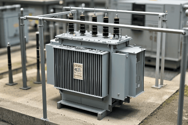
A dry type distribution transformer is an electrical device that changes voltage levels without using oil for insulation or cooling. It uses air and solid materials instead. This transformer works by electromagnetic induction, transferring electrical energy between two or more circuits through a shared magnetic field.
Let’s dive deeper into how these transformers work and why they’re so important for indoor power distribution.
The Basic Structure
Dry type transformers have a simple yet effective structure:
- Core: This is usually made of silicon steel laminations. It provides a path for the magnetic flux.
- Windings: These are typically made of copper or aluminum. They’re wrapped around the core.
- Insulation: Instead of oil, dry type transformers use solid insulation materials like epoxy resin.
How It Works
The working principle of a dry type transformer is fascinating:
- Primary Winding: When AC power enters the primary winding, it creates a changing magnetic field in the core.
- Magnetic Field: This field extends to the secondary winding.
- Secondary Winding: The changing magnetic field induces a voltage in the secondary winding.
- Voltage Change: The voltage change depends on the number of turns in each winding.
I once had to explain this to a client who was skeptical about switching to dry type transformers. I used a simple analogy: "Imagine the transformer as a gear system. The primary winding is like the input gear, the core is the connecting shaft, and the secondary winding is the output gear. The number of teeth on each gear determines the speed (or in our case, voltage) change."
Types of Dry Type Transformers
There are several types of dry type transformers:
- Cast Resin Transformers: These use epoxy resin for insulation.
- VPI (Vacuum Pressure Impregnated) Transformers: These are impregnated with varnish under vacuum.
- Open Wound Transformers: These have exposed windings and are used in specific industrial applications.
| Type | Insulation | Typical Use | Advantages |
|---|---|---|---|
| Cast Resin | Epoxy resin | Indoor, high moisture areas | Excellent moisture resistance |
| VPI | Varnish | General indoor use | Cost-effective, good performance |
| Open Wound | Air | Industrial, low humidity | Simple design, easy maintenance |
Understanding these types helps in choosing the right transformer for specific needs. In my experience, cast resin transformers are often the best choice for critical indoor applications due to their superior moisture resistance and fire safety.
Why Are Dry Type Transformers Gaining Popularity in Modern Buildings?
I’ve noticed a growing trend in modern building design. More and more architects and engineers are choosing dry type transformers. There’s a good reason for this shift.
Dry type transformers are gaining popularity in modern buildings due to their enhanced safety features, lower maintenance requirements, and eco-friendly design. They eliminate fire risks associated with oil-filled transformers, require less space, and align with green building standards.
Let’s explore the reasons behind this growing popularity and why it matters for modern building design.
Safety First
Safety is always my top priority when designing power systems. Dry type transformers excel in this area:
- Fire Safety: They don’t use flammable oil, greatly reducing fire risk.
- No Oil Leaks: This eliminates the risk of oil spills and associated hazards.
- Indoor Friendly: They can be safely installed close to the point of use.
I once worked on a project for a high-rise office building. The client was concerned about fire safety. When I explained how dry type transformers eliminate the risk of oil fires, they were immediately sold on the idea.
Space Efficiency
In modern buildings, space is often at a premium. Dry type transformers offer significant advantages:
- Compact Design: They’re generally smaller than oil-filled transformers.
- No Oil Containment: This saves even more space in the installation area.
- Flexible Installation: They can be installed in various orientations.
Low Maintenance
Building managers appreciate the low maintenance requirements of dry type transformers:
- No Oil Checks: There’s no need for regular oil testing or replacement.
- Simple Inspections: Visual checks are often sufficient.
- Longer Life: With proper care, they can last for decades.
Eco-Friendly Design
Modern buildings often aim for green certifications. Dry type transformers can help:
- No Oil Disposal: This eliminates a potential environmental hazard.
- Energy Efficient: Many models offer high efficiency ratings.
- Recyclable Materials: Many components can be recycled at end-of-life.
| Feature | Benefit for Modern Buildings |
|---|---|
| Fire Safety | Reduces insurance costs, meets strict safety codes |
| Space Efficiency | Allows for more rentable space in the building |
| Low Maintenance | Reduces operational costs over time |
| Eco-Friendly | Helps achieve green building certifications |
In my experience, the combination of these factors makes dry type transformers an attractive choice for modern building designers. They align well with the goals of safety, efficiency, and sustainability that are so important in contemporary architecture.
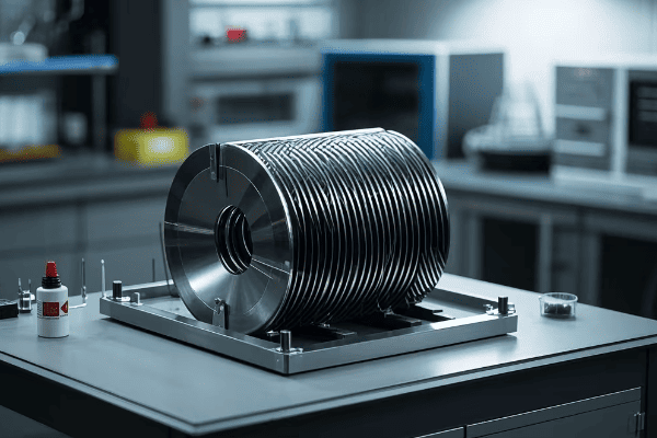
The Core of Dry Type Transformers: Understanding Its Critical Role?
The core of a dry type transformer might not be visible, but it’s the heart of the device. I’ve found that many people overlook its importance. Let’s change that.
The core of a dry type transformer plays a critical role in its operation. It provides a path for the magnetic flux, enabling the transfer of energy between the primary and secondary windings. The core’s design and material significantly impact the transformer’s efficiency, size, and performance.
Let’s dive deeper into the world of transformer cores and why they’re so crucial for the performance of dry type transformers.
Core Materials
The choice of core material is crucial:
- Silicon Steel: This is the most common material. It offers a good balance of performance and cost.
- Amorphous Metal: This newer material can reduce energy losses by up to 70% compared to silicon steel.
- Nanocrystalline Materials: These offer even better performance but are currently very expensive.
I once worked on a project where we used amorphous metal cores. The energy savings were impressive, and the client was thrilled with the reduced operating costs.
Core Designs
There are several core designs, each with its own advantages:
- Core Type: The windings surround the core limbs.
- Shell Type: The core surrounds the windings.
- Toroidal: A ring-shaped core with windings wrapped around it.
The Role of the Core
The core serves several critical functions:
- Magnetic Flux Path: It provides a low-reluctance path for the magnetic flux.
- Energy Transfer: It enables the transfer of energy between the primary and secondary windings.
- Efficiency: A well-designed core minimizes energy losses.
Core Losses
Understanding core losses is crucial for optimizing transformer performance:
- Hysteresis Loss: This occurs due to the changing magnetic field.
- Eddy Current Loss: This is caused by currents induced in the core material.
To minimize these losses, cores are often made of thin laminations stacked together.
| Core Type | Advantages | Best For |
|---|---|---|
| Core Type | Good cooling, easy maintenance | General purpose |
| Shell Type | Better short-circuit strength | High current applications |
| Toroidal | Very low stray magnetic field | Sensitive electronic equipment |
In my experience, the choice of core design and material can make a significant difference in transformer performance. I always pay close attention to these factors when designing or specifying transformers for a project.
Dry vs. Oil Type Transformers: A Comprehensive Comparison?
I’ve worked with both dry and oil type transformers throughout my career. Each has its strengths and weaknesses. Let’s compare them to see which might be best for your needs.
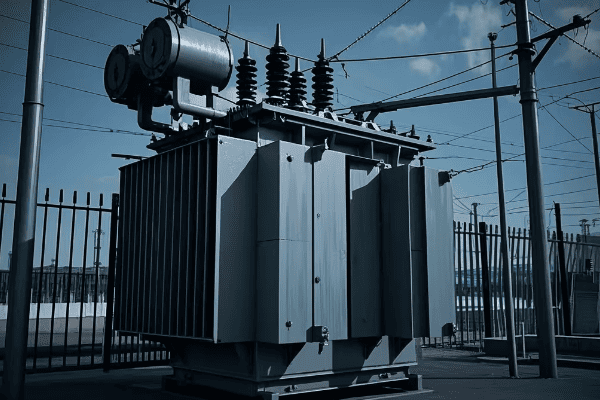
Dry type transformers offer better fire safety and environmental protection, while oil type transformers generally have better cooling and overload capacity. Dry types are preferred for indoor and environmentally sensitive locations, while oil types are often used for outdoor and high-capacity applications.
Let’s dive deeper into the key differences between these two transformer types.
Safety Considerations
Safety is always my top priority:
-
Fire Risk:
- Dry Type: Low fire risk due to absence of flammable oil.
- Oil Type: Higher fire risk due to presence of flammable oil.
-
Environmental Risk:
- Dry Type: No risk of oil leaks or spills.
- Oil Type: Potential for oil leaks, requiring containment measures.
I once worked on a project for a hospital where we chose dry type transformers specifically for their superior fire safety.
Performance and Efficiency
Performance can vary depending on the application:
-
Cooling Efficiency:
- Dry Type: Air-cooled, less efficient for heat dissipation.
- Oil Type: Oil provides excellent cooling, allowing for better overload capacity.
-
Noise Levels:
- Dry Type: Generally quieter operation.
- Oil Type: Can be noisier, especially with cooling fans.
-
Efficiency:
- Dry Type: Slightly less efficient, especially at partial loads.
- Oil Type: Often more efficient, particularly in larger sizes.
Maintenance and Lifespan
Maintenance needs can significantly impact long-term costs:
-
Routine Maintenance:
- Dry Type: Lower maintenance requirements, no oil testing needed.
- Oil Type: Regular oil testing and potential oil replacement required.
-
Lifespan:
- Dry Type: Typical lifespan of 20-30 years.
- Oil Type: Can last 30-40 years or more with proper maintenance.
Installation and Space Requirements
Space considerations are often crucial:
-
Space Needs:
- Dry Type: Generally more compact, no need for oil containment.
- Oil Type: Requires more space, including area for oil containment.
-
Weight:
- Dry Type: Typically lighter.
- Oil Type: Heavier, may require additional structural support.
| Feature | Dry Type | Oil Type |
|---|---|---|
| Fire Safety | High | Lower |
| Environmental Risk | Low | Higher |
| Cooling Efficiency | Lower | High |
| Maintenance | Low | Higher |
| Lifespan | 20-30 years | 30-40+ years |
| Space Requirements | Lower | Higher |
| Best For | Indoor, sensitive environments | Outdoor, high capacity |
In my experience, the choice between dry and oil type transformers often comes down to the specific needs of the project. For indoor applications, especially in sensitive environments, I usually recommend dry type transformers. For outdoor substations or very high capacity needs, oil type transformers might be the better choice.
Key Advantages of Dry Type Transformers for Indoor Applications?
When it comes to indoor power distribution, dry type transformers have some clear advantages. I’ve seen these benefits firsthand in many projects.
Dry type transformers excel in indoor applications due to their enhanced safety, reduced maintenance needs, and environmental friendliness. They eliminate fire and environmental risks associated with oil, require less space, and align well with green building standards. These factors make them ideal for use in commercial buildings, hospitals, and data centers.
Let’s explore these advantages in more detail and see why they matter for indoor applications.
Enhanced Safety
Safety is paramount in indoor environments:
- Fire Resistance: The absence of oil significantly reduces fire risk.
- No Oil Leaks: Eliminates the risk of oil spills and associated hazards.
- Reduced Explosion Risk: Lower risk of explosive failure compared to oil-filled transformers.
I once worked on a project for a large library. The client was particularly concerned about fire safety. The choice of dry type transformers gave them peace of mind.
Space Efficiency
In indoor settings, space is often at a premium:
- Compact Design: Generally smaller than equivalent oil-filled units.
- No Oil Containment Needed: Saves additional space.
- Flexible Installation: Can be installed closer to the load, saving on cable costs.
Low Maintenance Requirements
Building managers appreciate the ease of maintenance:
- No Oil Testing: Eliminates the need for regular oil testing and replacement.
- Simpler Inspections: Visual inspections are often sufficient.
- Longer Intervals Between Services: Reduces downtime and maintenance costs.
Environmental Benefits
Dry type transformers align well with green building initiatives:
- No Oil Disposal: Eliminates the need for hazardous waste disposal.
- Recyclable Materials: Many components can be recycled at end-of-life.
- Energy Efficiency: Many models offer high efficiency ratings.
Noise Reduction
Quiet operation is crucial in many indoor settings:
- Lower Noise Levels: Generally quieter than oil-filled transformers.
- No Cooling Fans: Many designs don’t require noisy cooling fans.
| Advantage | Benefit for Indoor Applications |
|---|---|
| Fire Safety | Crucial for occupied buildings |
| Space Efficiency | Maximizes usable floor space |
| Low Maintenance | Reduces operational costs |
| Environmental Benefits | Helps achieve green certifications |
| Noise Reduction | Improves occupant comfort |
In my experience, these advantages make dry type transformers the preferred choice for most indoor applications. They offer a combination of safety, efficiency, and environmental benefits that are hard to match with other transformer types.
Common Misconceptions About Dry Type Transformers: Debunking the Myths?
Throughout my career, I’ve encountered many misconceptions about dry type transformers. These myths can lead to poor decisions in power system design. Let’s clear up some of these misunderstandings.
Common misconceptions about dry type transformers include beliefs that they are less efficient, more expensive, and less durable than oil-filled types. In reality, modern dry type transformers are highly efficient, often more cost-effective in the long run, and can last for decades with proper care.
Let’s examine some of these myths in detail and see why they don’t hold up to scrutiny.
Myth 1: Dry Type Transformers Are Less Efficient
This is a common misconception I often hear:
Reality: While it’s true that some older dry type models were less efficient, modern designs have significantly improved. Many dry type transformers now offer efficiency levels comparable to or even exceeding oil-filled types.
Key Points:
- Advanced Materials: Use of materials like amorphous metal cores has greatly reduced losses.
- Design Improvements: Better winding techniques and insulation have improved efficiency.
- Regulation Compliance: Many dry type transformers meet or exceed efficiency standards.
I once worked on a project where we replaced old oil-filled transformers with modern dry types. The energy savings were substantial, surprising even the skeptical facility manager.
Myth 2: Dry Type Transformers Are Always More Expensive
Initial cost is often a concern:
Reality: While the upfront cost of dry type transformers can be higher, they often prove more cost-effective over their lifetime.
Key Points:
- Lower Maintenance Costs: No oil testing or replacement needed.
- Reduced Installation Costs: No need for oil containment systems.
- Longer Lifespan: Many dry type transformers last for decades with proper care.
- Lower Insurance Costs: Reduced fire risk can lead to lower insurance premiums.
Myth 3: Dry Type Transformers Can’t Handle Overloads
This misconception canThis misconception can lead to overdesign:
Reality: While it’s true that dry type transformers generally have lower overload capacity than oil-filled types, they can still handle short-term overloads when properly designed.
Key Points:
- Design Flexibility: Dry type transformers can be designed for specific overload requirements.
- Temperature Monitoring: Advanced monitoring systems can safely manage overload conditions.
- Cooling Options: Some designs incorporate forced air cooling for better overload handling.
In a data center project I worked on, we successfully used dry type transformers with forced air cooling to handle the variable loads typical in such environments.
Myth 4: Dry Type Transformers Are Not Suitable for Harsh Environments
This myth often limits their use:
Reality: While it’s true that standard dry type transformers are designed for indoor use, there are specially designed models for harsh environments.
Key Points:
- Enclosures: Dry type transformers can be housed in protective enclosures for outdoor use.
- Special Designs: Some models are specifically designed for high humidity or corrosive environments.
- Temperature Range: Many dry type transformers can operate in a wide temperature range.
I once specified a specially designed dry type transformer for a coastal industrial plant. It performed excellently despite the salty, humid environment.
| Myth | Reality |
|---|---|
| Less Efficient | Modern designs are highly efficient |
| More Expensive | Often more cost-effective over lifetime |
| Can’t Handle Overloads | Can be designed for overload capacity |
| Not for Harsh Environments | Special designs available for challenging conditions |
Debunking these myths is crucial for making informed decisions about transformer selection. In my experience, understanding the true capabilities of dry type transformers often leads to better, more efficient power system designs.
The Environmental Impact: How Dry Type Transformers Contribute to Sustainability?
As an engineer, I’ve always been interested in the environmental impact of the systems I design. Dry type transformers have a lot to offer in this regard. Let’s explore how they contribute to sustainability.
Dry type transformers contribute to sustainability through their eco-friendly design, energy efficiency, and long lifespan. They eliminate the risk of oil leaks, reduce the need for hazardous waste disposal, and often use recyclable materials. Their efficiency and durability also contribute to reduced energy consumption over time.
Let’s dive deeper into the environmental benefits of dry type transformers and why they matter in our increasingly eco-conscious world.
Elimination of Oil-Related Environmental Risks
This is perhaps the most obvious environmental benefit:
- No Oil Leaks: Eliminates the risk of soil and water contamination.
- No Oil Disposal: Removes the need for hazardous waste management.
- Reduced Fire Risk: Lowers the chance of environmentally damaging fires.
I once worked on a project near a protected wetland. The choice of dry type transformers was crucial in getting environmental approval for the development.
Energy Efficiency
Efficiency is key to reducing environmental impact:
- Low Losses: Modern dry type transformers have very low core and winding losses.
- Consistent Performance: Efficiency remains high even at partial loads.
- Cool Operation: Less energy wasted as heat compared to some oil-filled types.
Long Lifespan and Recyclability
Sustainability is about more than just operation:
- Durability: Many dry type transformers last 20-30 years or more.
- Recyclable Materials: Core and windings are often made of recyclable metals.
- Less Frequent Replacement: Longer lifespan means less frequent manufacturing and disposal.
Reduced Carbon Footprint
The overall impact on carbon emissions is significant:
- Manufacturing: Often requires less energy-intensive processes than oil-filled types.
- Transportation: Lighter weight can mean lower transport-related emissions.
- Operation: High efficiency leads to lower energy consumption over time.
Alignment with Green Building Standards
Dry type transformers can help achieve green certifications:
- LEED Points: Can contribute to LEED certification for buildings.
- Energy Star: Many models meet Energy Star efficiency requirements.
- Green Grid Initiatives: Align well with efforts to create more sustainable power grids.
| Environmental Aspect | Benefit of Dry Type Transformers |
|---|---|
| Oil-Related Risks | Eliminated |
| Energy Efficiency | High, reducing overall energy consumption |
| Lifespan | Long, reducing manufacturing and disposal impacts |
| Recyclability | High, especially for core and windings |
| Green Building Compliance | Often contributes to certifications |
In my experience, the environmental benefits of dry type transformers are becoming increasingly important. As sustainability becomes a key focus in many industries, the choice of transformer type can play a significant role in reducing a project’s overall environmental impact.
Conclusion
Dry type transformers are revolutionizing indoor power distribution. They offer enhanced safety, efficiency, and environmental benefits. As we move towards more sustainable and smart buildings, dry type transformers will play a crucial role in shaping our power systems.
Have you ever wondered how electricity from a power plant safely reaches your home appliances? The secret lies in the magical world of transformers, specifically step-up and step-down transformers.
Step-up transformers increase voltage while decreasing current, typically used in power plants to boost voltage for long-distance transmission. Step-down transformers do the opposite, reducing voltage and increasing current, commonly found in local substations and residential areas. The key difference lies in their winding ratios: step-up transformers have more secondary windings than primary, while step-down transformers have fewer.
As an electrical engineer with over 15 years of experience in power systems, I’ve worked extensively with both types of transformers. Let’s dive into the fascinating world of these voltage-changing marvels and uncover what makes each type unique and indispensable in our modern electrical grid.
How Do Step-Up Transformers Work?
Have you ever seen those massive transformers at power plants? Those are likely step-up transformers in action.
Step-up transformers increase voltage by having more turns in the secondary coil than in the primary coil. This results in a higher induced electromotive force (EMF) in the secondary coil compared to the primary voltage. The relationship is defined by the equation: Vs/Vp = Ns/Np, where V is voltage and N is the number of turns in each coil.

Key characteristics of step-up transformers:
- Secondary coil turns (N2) > Primary coil turns (N1)
- Secondary voltage (U2) > Primary voltage (U1)
- Secondary current (I2) < Primary current (I1)
- Power remains constant (P = VI) on both sides (ignoring small losses)
I remember working on a project at a wind farm where we used massive step-up transformers to increase the voltage from 690V (generated by the turbines) to 400kV for long-distance transmission. The sheer size of these transformers – some as big as a small house – was a testament to their crucial role in power distribution.
Key Takeaway: Step-up transformers are essential for efficient long-distance power transmission, allowing electricity to travel hundreds of miles with minimal losses.
What Makes Step-Down Transformers Different?
Ever noticed those barrel-shaped devices on utility poles in your neighborhood? Those are likely step-down transformers, bringing high-voltage power down to a level safe for your home.
Step-down transformers decrease voltage by having fewer turns in the secondary coil compared to the primary coil. This results in a lower induced EMF in the secondary coil. The same principle applies: Vs/Vp = Ns/Np, but in this case, Ns is smaller than Np.
Key characteristics of step-down transformers:
- Secondary coil turns (N2) < Primary coil turns (N1)
- Secondary voltage (U2) < Primary voltage (U1)
- Secondary current (I2) > Primary current (I1)
- Power remains constant (P = VI) on both sides (ignoring small losses)
In a recent urban development project, we installed numerous step-down transformers to reduce the 11kV distribution voltage to the 230V used in homes. It’s fascinating to think that these relatively small devices are the final link in a chain that starts at massive power plants.
Key Takeaway: Step-down transformers are crucial for delivering usable power to end consumers, ensuring safe voltage levels for homes and businesses.
How Do Step-Up and Step-Down Transformers Compare?
Understanding the differences between step-up and step-down transformers is crucial for anyone involved in electrical engineering or power distribution. Let’s break it down:
The main difference between step-up and step-down transformers lies in their winding ratios and their effect on voltage and current. While step-up transformers increase voltage and decrease current, step-down transformers do the opposite. Both types play crucial roles in different parts of the power distribution system.
Here’s a comparison table to highlight the key differences:
| Feature | Step-Up Transformer | Step-Down Transformer |
|---|---|---|
| Winding Ratio | N2 > N1 | N2 < N1 |
| Voltage Change | Increases (U2 > U1) | Decreases (U2 < U1) |
| Current Change | Decreases (I2 < I1) | Increases (I2 > I1) |
| Primary Use | Power generation plants | Distribution substations, residential areas |
| Typical Input Voltage | 11kV – 33kV | 33kV – 765kV |
| Typical Output Voltage | 132kV – 765kV | 11kV – 415V |
| Core Size | Larger | Smaller |
| Winding Wire Gauge | Thicker primary, thinner secondary | Thicker secondary, thinner primary |
I once worked on a project that involved tracing electricity from a power plant to a residential area. We started with a massive step-up transformer at the plant, increasing voltage from 20kV to 400kV for transmission. Then, at various substations along the way, we used step-down transformers to gradually reduce the voltage, ending with small transformers on local poles that brought the voltage down to 230V for household use.
Key Takeaway: Both step-up and step-down transformers are essential components of our power distribution system, each serving a specific purpose in ensuring efficient and safe electricity delivery.
What Are the Future Trends in Transformer Technology?
As our energy landscape evolves, so does transformer technology. But what does the future hold for these essential devices?
Future trends in transformer technology focus on increased efficiency, smart monitoring capabilities, and environmental sustainability. We’re seeing developments in high-temperature superconducting materials, solid-state transformers, and integration with smart grid technologies for both step-up and step-down transformers.
Emerging trends include:
- Use of amorphous metal cores to reduce energy losses
- Implementation of biodegradable insulating fluids
- Integration of IoT sensors for real-time monitoring and predictive maintenance
- Development of compact, modular designs for urban installations
- Enhanced resilience against cyber threats in smart grid applications
In a recent pilot project, we tested solid-state transformers that can handle AC and DC conversion, potentially revolutionizing how we integrate renewable energy sources and electric vehicle charging stations into the grid.
Key Takeaway: The future of transformer technology lies in smarter, more efficient, and more flexible designs that can adapt to the changing needs of our evolving power systems.
Conclusion
Understanding the differences between step-up and step-down transformers is crucial for grasping how our modern electrical grid functions. From the massive step-up transformers at power plants to the small step-down units in your neighborhood, these devices work in harmony to ensure safe and efficient power delivery. As we move towards a future with more distributed energy resources and smart grids, the role of transformers will continue to evolve, making this field an exciting area for innovation and development.
FAQs: Common Questions About Step-Up and Step-Down Transformers
- Can a step-up transformer be used as a step-down transformer?
Theoretically, yes. The direction of voltage change depends on which side you use as the primary. However, in practice, transformers are designed and optimized for specific step-up or step-down ratios. Using a transformer in the opposite direction can lead to inefficiencies and potential safety issues. Always use transformers as designed for optimal performance and safety.
- Do transformers consume power?
Transformers don’t consume power in the sense of converting it to another form of energy, but they do have some power losses. These losses are primarily due to core losses (hysteresis and eddy currents) and copper losses in the windings. Modern transformers are highly efficient, with large power transformers achieving efficiencies up to 99.75%. However, even small losses can be significant when dealing with large amounts of power.
- Why don’t we use higher voltages all the way to our homes?
While higher voltages are more efficient for long-distance transmission, they’re extremely dangerous and impractical for home use. The insulation required for high voltages would make home wiring prohibitively expensive and bulky. Additionally, high voltages can cause corona discharge and other safety issues. Step-down transformers allow us to balance the efficiency of high-voltage transmission with the safety and practicality of low-voltage distribution.
- How long do transformers typically last?
With proper maintenance, power transformers can last 30-40 years or even longer. I’ve worked with transformers that have been in service for over 50 years and are still functioning well. However, lifespan can vary depending on factors like load conditions, environmental factors, and maintenance practices. Regular monitoring and maintenance are key to extending a transformer’s operational life.
- Are there any alternatives to traditional transformers?
Yes, emerging technologies are challenging traditional transformer designs. Solid-state transformers, which use power electronics to convert voltage levels, are a promising alternative. They offer benefits like smaller size, lighter weight, and the ability to handle both AC and DC power. However, as of now, they’re generally more expensive and less efficient than traditional transformers for high-power applications. Research is ongoing, and we may see more widespread adoption of these alternatives in the future, especially in specific applications like renewable energy integration and electric vehicle charging.
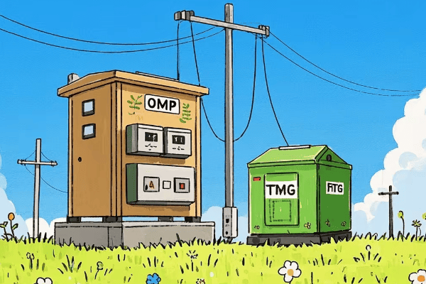
Have you ever wondered why some electrical transformers are shaped like cylinders while others look like boxes with fins? The answer lies in the specific design of OMP and TMG transformers, two crucial components in our power distribution systems.
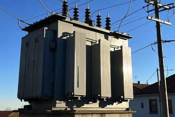
OMP transformers are single-phase, oil-immersed units designed for voltage step-down in various applications, including electrical supply networks and railroad systems. TMG transformers, on the other hand, are three-phase, oil-immersed units in hermetic corrugated cases, primarily used for transforming electrical energy in supply networks and consumer mains. Both types play vital roles in power distribution but have distinct characteristics suited for different applications.
As an electrical engineer with over 15 years of experience in power systems, I’ve worked extensively with both OMP and TMG transformers. Let’s dive into the world of these essential devices and uncover what makes each type unique and indispensable in modern power distribution.
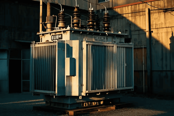
What Are OMP Transformers and Where Are They Used?
Have you ever seen a small cylindrical transformer mounted on a utility pole? Chances are, you’ve spotted an OMP transformer in action.
OMP transformers are single-phase, oil-immersed converter transformers designed for stepping down voltage in electrical supply networks. They’re commonly used in power circuits of alarm equipment and railroad automatic block systems. These transformers are built to withstand extreme temperatures, operating efficiently in both temperate (-45°C to +40°C) and cold (-60°C to +40°C) climates.
Key features of OMP transformers include:
- Single-phase design
- Oil-immersed for better insulation and cooling
- Compact cylindrical shape
- Wide temperature operating range
- Primarily used for voltage step-down
I recall a project where we installed OMP transformers along a new railroad line in a mountainous region. The transformers’ ability to operate in extreme cold was crucial for maintaining reliable signaling systems throughout the harsh winter months.
Key Takeaway: OMP transformers are versatile, robust units ideal for outdoor installations in challenging environments, particularly where single-phase power is needed.
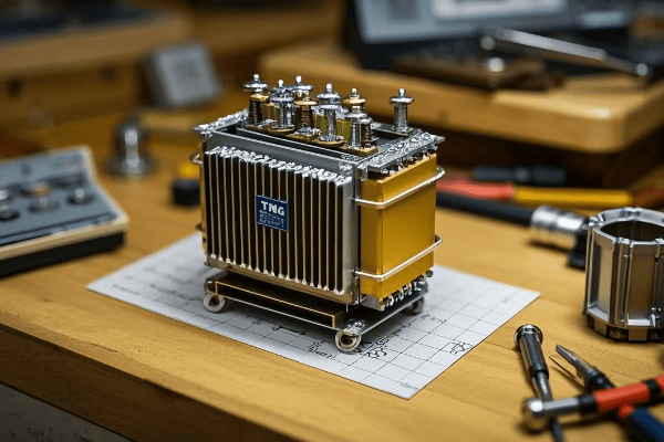
What Makes TMG Transformers Unique?
Ever noticed those large, finned boxes in electrical substations? Those are likely TMG transformers, the workhorses of power distribution.
TMG transformers are three-phase, oil-immersed units housed in hermetic corrugated cases. They’re designed for transforming electrical energy in supply networks and consumer mains. A key advantage of TMG transformers is their low maintenance requirements – they need no preventive repair or inspection throughout their operational lifetime, making them cost-effective for long-term use.
Distinctive features of TMG transformers include:
- Three-phase design
- Hermetically sealed corrugated case
- Low maintenance requirements
- Suitable for both indoor and outdoor installations
- Used in larger power distribution applications
In a recent urban development project, we chose TMG transformers for the main power distribution substations. Their low maintenance needs and reliable performance were perfect for the high-demand, continuous operation required in a growing city center.
Key Takeaway: TMG transformers offer a low-maintenance, reliable solution for three-phase power transformation, ideal for both utility and industrial applications.
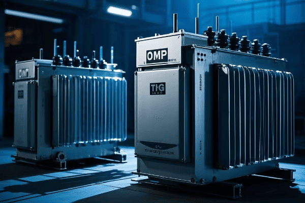
How Do OMP and TMG Transformers Compare?
Choosing between OMP and TMG transformers can significantly impact your power distribution system’s efficiency and reliability. But how do they stack up against each other?
OMP and TMG transformers differ in phase count, application scope, and maintenance needs. While OMP transformers excel in single-phase, outdoor applications with extreme temperature variations, TMG transformers are preferred for three-phase systems where low maintenance and hermetic sealing are priorities.
Here’s a comparison table to highlight the key differences:
| Feature | OMP Transformer | TMG Transformer |
|---|---|---|
| Phase | Single-phase | Three-phase |
| Design | Cylindrical, oil-immersed | Rectangular, hermetically sealed |
| Temperature Range | -60°C to +40°C | Standard range (typically -20°C to +40°C) |
| Main Applications | Railroad systems, alarm circuits | Supply networks, consumer mains |
| Maintenance | Regular inspection needed | Minimal maintenance required |
| Size | Generally smaller | Larger, suited for higher capacities |
| Installation | Often pole-mounted | Usually ground-mounted |
I once consulted on a project where we needed to decide between OMP and TMG transformers for a mixed-use development. We ultimately chose OMP transformers for the residential areas due to space constraints and single-phase requirements, while opting for TMG transformers in the commercial sector to handle the higher three-phase power demands.
Key Takeaway: The choice between OMP and TMG transformers depends on specific application needs, considering factors like phase requirements, installation environment, and maintenance capabilities.
What Are the Future Trends in Transformer Technology?
As our power needs evolve, so do our transformers. But what does the future hold for OMP and TMG transformers?
Future trends in transformer technology are focusing on increased efficiency, smart monitoring capabilities, and environmental sustainability. For both OMP and TMG transformers, we’re seeing developments in biodegradable insulating oils, advanced cooling systems, and integration with smart grid technologies.
Emerging trends include:
- Use of natural ester fluids as an eco-friendly alternative to mineral oil
- Integration of IoT sensors for real-time monitoring and predictive maintenance
- Development of more compact designs for urban installations
- Improved energy efficiency to reduce losses
- Enhanced resilience against cyber threats in smart grid applications
In a recent pilot project, we tested new OMP transformers with biodegradable insulating fluid and built-in smart monitoring systems. The results were promising, showing improved environmental performance and the potential for significant long-term cost savings through predictive maintenance.
Key Takeaway: The future of both OMP and TMG transformers lies in smarter, more efficient, and environmentally friendly designs that can meet the evolving demands of our power distribution systems.
Conclusion
Understanding the differences between OMP and TMG transformers is crucial for anyone involved in power distribution system design or management. While OMP transformers offer flexibility and resilience in single-phase, often challenging environments, TMG transformers provide reliable, low-maintenance solutions for three-phase power distribution. As technology advances, both types are evolving to meet the demands of smarter, more efficient power grids. Whether you’re working on a small-scale project or a large power distribution network, choosing the right transformer type can significantly impact the system’s performance, reliability, and long-term cost-effectiveness.
FAQs: Common Questions About OMP and TMG Transformers
- Are OMP transformers more efficient than TMG transformers?
Efficiency depends on the specific application. OMP transformers are generally more efficient for smaller, single-phase applications, especially in variable temperature conditions. TMG transformers, however, can be more efficient in larger, three-phase systems due to their design and lower maintenance needs. In my experience, the efficiency difference is usually minimal when each type is used in its intended application.
- Can TMG transformers be used in extremely cold climates like OMP transformers?
While TMG transformers are robust, they’re typically not designed for the extreme temperature ranges that OMP transformers can handle. For very cold climates (below -40°C), OMP transformers are usually the better choice. However, special versions of TMG transformers can be manufactured for colder climates if necessary.
- How long do OMP and TMG transformers typically last?
Both OMP and TMG transformers are built for longevity. With proper maintenance, OMP transformers can last 20-30 years, while TMG transformers, due to their hermetic design and lower maintenance needs, often last 30-40 years or more. I’ve seen TMG transformers in operation for over 50 years, still performing efficiently.
- Are there any special installation requirements for OMP and TMG transformers?
Yes, there are. OMP transformers, being often pole-mounted, require proper support structures and consideration for weight distribution. TMG transformers, typically larger and ground-mounted, need a stable foundation and adequate clearance for cooling. Both types require proper electrical protection and grounding. Always consult local electrical codes and manufacturer guidelines for specific installation requirements.
- Can OMP and TMG transformers be used with renewable energy sources?
Yes, both can be adapted for use with renewable energy sources. However, the choice depends on the specific renewable system. For example, small-scale solar installations might use OMP transformers, while large wind farms typically require TMG transformers for their three-phase output. In recent years, I’ve seen an increase in specialized transformer designs optimized for renewable energy applications, incorporating features like enhanced harmonics handling and bidirectional power flow capabilities.
What Is a Station Transformer?
Many buyers and engineers struggle to understand what a station transformer is and why it’s essential for grid safety. Choosing the wrong transformer or ignoring its role can lead to costly outages, inefficiency, and safety risks. This guide explains station transformers, their types, prices, and technologies—helping you select the right solution for a stable and efficient power system
A station transformer is a large electrical device that converts high-voltage electricity from power plants to lower voltages suitable for distribution to homes and businesses. These transformers are essential components of power substations, capable of handling voltages up to 765,000 volts and weighing up to 400 tons. Without station transformers, our modern electrical grid simply couldn’t function.

As an electrical engineer with over 15 years of experience in power distribution, I’ve seen firsthand how crucial these transformers are to our daily lives. Let’s dive into the world of station transformers and uncover why they’re the unsung heroes of our electrical infrastructure.
How Do Station Transformers Work?
Ever wondered why we don’t just send electricity straight from power plants to our homes? The answer lies in the fascinating operation of station transformers.
Station transformers work on the principle of electromagnetic induction1. They use two sets of coils – primary and secondary – wound around an iron core. When alternating current passes through the primary coil, it creates a changing magnetic field, which induces a voltage in the secondary coil. By varying the number of turns in each coil, the transformer can step voltage up or down as needed.

station transformer working principle diagram
Here’s a breakdown of the process:
- High-voltage electricity enters the primary coil
- The alternating current creates a changing magnetic field in the iron core
- This magnetic field induces a voltage in the secondary coil
- The voltage in the secondary coil depends on the ratio of turns between primary and secondary coils
I once worked on a project to upgrade a substation where we installed a new 500 kV to 230 kV station transformer. The sheer size of the unit – about the size of a small house – was a stark reminder of the immense power these devices handle.
Key Takeaway: Station transformers are the vital link between power generation and distribution, enabling the safe and efficient transfer of electricity across vast distances.
Types of Station Transformers Explained
Did you know that not all station transformers are created equal? The type of transformer used can significantly impact the efficiency and reliability of power distribution.
Station transformers come in several types, including step-down transformers, step-up transformers, and autotransformers. The most common in distribution substations are step-down transformers, which reduce high transmission voltages to lower distribution voltages. Step-up transformers are used at power plants to increase voltage for long-distance transmission, while autotransformers are used for smaller voltage changes.
Here’s a quick comparison of the main types:
| Type | Primary Use | Typical Voltage Change |
|---|---|---|
| Step-Down | Distribution Substations | 500 kV to 69 kV |
| Step-Up | Power Plants | 20 kV to 765 kV |
| Autotransformer | Transmission Substations | 345 kV to 138 kV |

In my career, I’ve worked with all these types. I remember a particularly challenging project involving the installation of a massive step-up transformer at a new wind farm. The transformer was crucial in converting the 34.5 kV output from the wind turbines to 345 kV for long-distance transmission.
Key Takeaway: The choice of transformer type depends on its specific role in the power system, with each type optimized for certain voltage transformations.
Why Station Transformers Are Critical for Grid Stability
Have you ever experienced a widespread power outage? The stability of our electrical grid often hinges on the reliable operation of station transformers.
Station transformers play a crucial role in maintaining grid stability. They help regulate voltage levels, manage power flow, and isolate faults in the system. Advanced station transformers are equipped with on-load tap changers (OLTC)2 that can adjust voltage ratios in real-time, helping to maintain consistent voltage levels even as demand fluctuates throughout the day.

Diagram showing how transformers contribute to grid stability
Here’s how station transformers contribute to grid stability:
- Voltage Regulation: OLTCs adjust transformer ratios to maintain steady voltages
- Fault Isolation: Transformers can help isolate faulty sections of the grid
- Power Flow Control: By adjusting voltage levels, transformers can influence power flow directions
- Reactive Power Compensation: Some transformers are designed to provide reactive power support
I once led a team that implemented a smart grid project, integrating advanced monitoring systems with station transformers. The real-time data from these transformers allowed us to predict and prevent potential instabilities, significantly reducing the number of outages in the region.
Key Takeaway: Station transformers are not just passive voltage converters; they’re active players in maintaining the stability and reliability of our electrical grid.
New Technologies in Station Transformers (2025 Guide)
As our energy landscape changes, so too must our infrastructure. But how are station transformers keeping up with these changes?
Modern station transformers are evolving to meet the challenges of a changing energy landscape. Innovations include the use of more efficient core materials, advanced cooling systems, and the integration of smart monitoring technologies. Some cutting-edge transformers even incorporate superconducting materials, promising higher efficiency and smaller footprints.
Key technological advancements in station transformers include:
- Amorphous Metal Cores: Reducing energy losses by up to 70% compared to traditional silicon steel
- Ester-based Insulating Fluids: Biodegradable and fire-resistant alternatives to mineral oil
- IoT Integration: Real-time monitoring of transformer health and performance
- Phase-Shifting Transformers: Allowing greater control over power flow in the grid
In a recent project, we retrofitted an older substation with these new technologies. The improvement in efficiency and reliability was remarkable, with energy losses reduced by nearly 30% and maintenance needs significantly decreased.
Key Takeaway: The evolution of station transformer technology is key to creating a more efficient, reliable, and sustainable power grid for the future.
Conclusion
Station transformers are the unsung heroes of our electrical infrastructure. From enabling the long-distance transmission of power to ensuring the lights stay on in our homes, these devices play a crucial role in our daily lives. As we move towards a future with more renewable energy sources and smarter grids, the importance of advanced, efficient station transformers will only grow. Understanding these critical components helps us appreciate the complexity and marvel of the power systems that underpin our modern world.

👉 Need help selecting the right transformer? Contact CHBEB for a tailored solution or Download our full transformer catalog here.
FAQs About Station Transformers
1.How long do station transformers last?
Station transformers are built to last, with a typical lifespan of 30 to 40 years. However, with proper maintenance and upgrades, many can operate effectively for 50 years or more. I’ve personally worked with transformers that were over 60 years old and still functioning well, though they required more frequent maintenance.
2.Are station transformers dangerous?
While station transformers handle extremely high voltages, they are designed with multiple safety features and are generally very safe when properly maintained. However, they can be dangerous if mishandled. That’s why substations have restricted access and why only trained professionals should work on or near these devices.
3.How efficient are modern transformers?
Modern large power transformers can achieve efficiencies of up to 99.75%. This might seem high, but when you’re dealing with massive amounts of power, even a small percentage of loss can be significant. For example, a 99.5% efficient 100 MVA transformer still loses about 500 kW – enough to power several hundred homes!
4.Can they handle renewable energy?
Yes, but it often requires some adaptation. Renewable sources like wind and solar can have variable outputs, which can stress traditional transformers. Modern transformers are being designed with this in mind, incorporating features like more robust insulation and advanced cooling systems to handle the fluctuations associated with renewable energy.
5.How are station transformers cooled?
Cooling is crucial for station transformers due to the heat generated by electrical losses. Most large transformers use oil as both an insulator and coolant. The oil circulates through the transformer, carrying heat to external radiators where it’s cooled. Some modern designs use alternative fluids or even gas for cooling. In my experience, proper cooling can significantly extend a transformer’s lifespan and improve its efficiency.
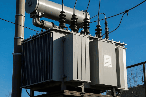
Have you ever wondered how the countless chemicals we use daily are produced? The secret often lies in specialized devices called chemical reactors. But did you know that there are different types of reactors, each designed for specific reactions?
Chemical reactors are classified into five main types based on their mode of operation and heat transfer: Batch Reactors, Continuous Stirred Tank Reactors (CSTR), Plug Flow Reactors (PFR), Fixed Bed Reactors (FBR), and Fluidized Bed Reactors (FBR). Each type has unique characteristics that make it suitable for different chemical processes, from small-scale laboratory experiments to large industrial productions.
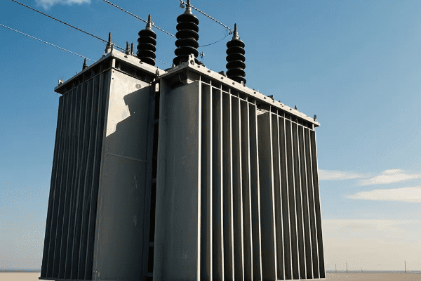
As a chemical engineer with over 15 years of experience in reactor design, I’ve seen firsthand how choosing the right reactor can make or break a chemical process. Let’s dive into each type and uncover what makes them unique and essential in the world of chemical engineering.
What is a Batch Reactor and When is it Used?
Have you ever baked a cake? If so, you’ve used a process similar to a batch reactor. But what makes this reactor type special in the chemical industry?
A batch reactor is the simplest type of chemical reactor, operating in a discontinuous mode. Reactants are added at the start, the reaction proceeds, and products are removed at the end. It’s ideal for small-scale production, testing new processes, and reactions that require long processing times. Heat transfer in batch reactors is mainly through conduction and radiation.
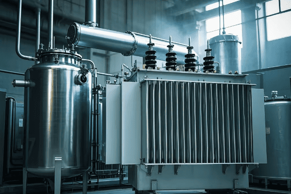
Let’s break down the key features of batch reactors:
- Operation Mode: Discontinuous (start and stop for each batch)
- Mixing: Usually equipped with stirrers for uniform mixing
- Temperature Control: Often operated at constant temperature
- Versatility: Can handle a wide range of reactions and formulations
- Scale: Suitable for small to medium-scale production
I remember a project where we used a batch reactor to develop a new pharmaceutical product. The flexibility of the batch process allowed us to easily adjust parameters between runs, which was crucial for optimizing the formulation.
Key Takeaway: Batch reactors are ideal for processes that require careful control and flexibility, especially in product development stages or for small-scale, high-value products.
How Does a Continuous Stirred Tank Reactor (CSTR) Work?
Imagine a pot of soup that’s constantly being stirred, with ingredients continuously added and the soup simultaneously removed. That’s essentially how a CSTR operates. But why is this type of reactor so popular in the chemical industry?
A Continuous Stirred Tank Reactor (CSTR) operates in a continuous mode, with reactants constantly fed in and products continuously removed. It features a well-designed stirring system that ensures uniform mixing. CSTRs are widely used in the chemical industry due to their steady-state operation and efficient heat transfer through convection.

Key characteristics of CSTRs include:
- Operation Mode: Continuous
- Mixing: Excellent, due to constant stirring
- Temperature Control: Typically operated at constant temperature and pressure
- Steady State: Achieves and maintains steady-state conditions
- Heat Transfer: Primarily through convection
In my career, I’ve implemented CSTRs in various processes, from wastewater treatment to polymer production. Their ability to maintain consistent conditions makes them invaluable for processes that require precise control.
Key Takeaway: CSTRs are the workhorses of the chemical industry, offering consistent output and excellent control, making them ideal for large-scale, continuous production processes.
What Makes Plug Flow Reactors (PFR) Unique?
Have you ever watched a conveyor belt move products through an assembly line? A Plug Flow Reactor works on a similar principle, but for chemicals. What makes this design so effective for certain reactions?
Plug Flow Reactors (PFRs) are tubular reactors where reactants flow continuously through a pipe or series of pipes. They’re characterized by minimal mixing in the flow direction, creating a "plug" of material moving through the reactor. PFRs are ideal for reactions requiring high uniformity in reaction rate and heat transfer, often used in gas-phase reactions and continuous processing.
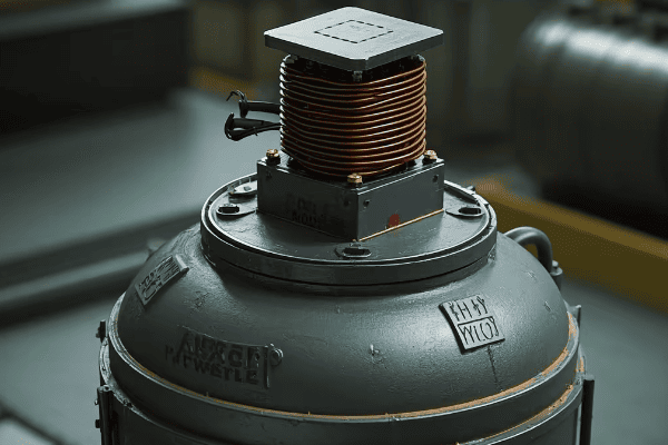
Key features of PFRs include:
- Flow Pattern: Continuous, with minimal axial mixing
- Reaction Progress: Changes along the length of the reactor
- Temperature Profile: Can be constant or vary along the reactor
- Heat Transfer: Mainly through convection
- Applications: Ideal for gas-phase reactions and high-throughput processes
I once worked on optimizing a PFR for the production of biodiesel. The uniform flow pattern allowed us to precisely control the reaction conditions, resulting in a significant increase in product quality and yield.
Key Takeaway: PFRs excel in processes that benefit from a controlled reaction environment and are particularly useful for gas-phase reactions or where product quality depends on precise reaction time.
How Do Fixed Bed Reactors (FBR) Enhance Catalytic Reactions?
Think of a Fixed Bed Reactor as a tube filled with catalytic beads, much like a water filter. But instead of filtering water, it’s facilitating chemical reactions. Why is this design so effective for catalytic processes?
Fixed Bed Reactors (FBRs) consist of a bed of solid catalyst particles through which reactants pass. The reaction occurs on the catalyst surface, making FBRs ideal for heterogeneous catalysis. They offer high conversion rates and are widely used in petroleum refining, chemical synthesis, and environmental applications.
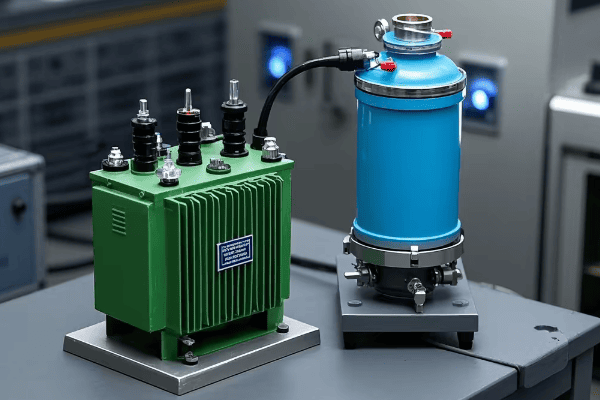
Key aspects of Fixed Bed Reactors include:
- Catalyst Arrangement: Packed bed of solid catalyst particles
- Flow Pattern: Typically downward flow of reactants
- Pressure Drop: Significant across the bed
- Heat Transfer: Mainly through convection, can be challenging to control
- Versatility: Can be used for both gas and liquid phase reactions
In my experience with FBRs, one of the most challenging aspects is managing heat transfer, especially in highly exothermic reactions. I once worked on a project where we implemented an innovative cooling system in an FBR used for ammonia synthesis, significantly improving efficiency and catalyst lifespan.
Key Takeaway: FBRs are powerhouses for catalytic reactions, offering high conversion rates and efficient use of catalyst material, but require careful design to manage heat transfer and pressure drop.
What Advantages Do Fluidized Bed Reactors (FBR) Offer?
Imagine a bed of sand with air blowing through it, causing the sand to behave almost like a fluid. This is the principle behind Fluidized Bed Reactors. But how does this unique design benefit chemical processes?
Fluidized Bed Reactors (FBRs) use a bed of solid particles (often catalyst) that is fluidized by passing gas or liquid through it. This creates a fluid-like behavior of the solid particles, offering excellent heat and mass transfer characteristics. FBRs are widely used in processes requiring efficient heat transfer, such as coal gasification, fluid catalytic cracking, and certain polymerization reactions.
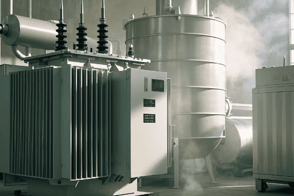
Key features of Fluidized Bed Reactors include:
- Particle Behavior: Solid particles behave like a fluid when gas or liquid passes through
- Heat Transfer: Excellent, due to high mixing and large surface area
- Mass Transfer: Enhanced by the movement of particles
- Temperature Control: Uniform temperature throughout the bed
- Scalability: Easily scalable for industrial processes
I’ve worked with FBRs in the petrochemical industry, particularly in fluid catalytic cracking units. The ability of these reactors to handle large volumes of feedstock while maintaining excellent heat transfer made them indispensable for efficient crude oil processing.
Key Takeaway: Fluidized Bed Reactors excel in processes that benefit from excellent heat and mass transfer, making them ideal for reactions involving rapid heat exchange or those requiring uniform temperature distribution.
Conclusion
Understanding the different types of chemical reactors is crucial for anyone involved in chemical engineering or process design. Each reactor type – from the simple batch reactor to the complex fluidized bed reactor – has its unique advantages and best-suited applications. The choice of reactor can significantly impact process efficiency, product quality, and overall economics of a chemical operation. As we continue to innovate in chemical processing, these reactor designs will evolve, but their fundamental principles will remain the cornerstone of chemical engineering.
FAQs: Common Questions About Chemical Reactors
- Which reactor type is best for small-scale, diverse chemical production?
Batch reactors are typically best for small-scale, diverse chemical production. They offer flexibility in operation, easy cleaning between batches, and are ideal for producing small quantities of different products. This makes them perfect for specialty chemicals, pharmaceuticals, and product development stages.
- How do continuous reactors like CSTRs and PFRs compare in terms of efficiency?
CSTRs and PFRs have different efficiency profiles:
- CSTRs offer excellent mixing and are good for reactions where constant conditions are needed throughout.
- PFRs provide better conversion for many reactions due to their concentration gradient along the reactor length.
The choice depends on the specific reaction kinetics and process requirements. In my experience, PFRs often show higher efficiency for simple, single-step reactions, while CSTRs excel in complex reaction systems requiring uniform conditions.
- Can different reactor types be combined in a single process?
Yes, combining reactor types is common in complex chemical processes. For example:
- A CSTR followed by a PFR can optimize yield in some reaction systems.
- A fluidized bed reactor might be used for a main reaction, followed by a fixed bed reactor for product purification.
I’ve worked on a process where we used a CSTR for initial mixing and reaction, followed by a PFR for final conversion, which significantly improved overall yield and product quality.
- How do environmental regulations impact reactor choice and design?
Environmental regulations significantly influence reactor choice and design, particularly in terms of:
- Emissions control: Reactors may need to be designed with better sealing or off-gas treatment systems.
- Energy efficiency: Regulations may push for more energy-efficient designs, favoring reactors with better heat integration.
- Waste reduction: Reactor choice might be influenced by the ability to minimize or easily treat waste products.
In recent years, I’ve seen a trend towards more compact, efficient reactor designs that minimize environmental impact while maximizing productivity.
- What are the latest innovations in reactor design?
Recent innovations in reactor design include:
- Microreactors: Extremely small reactors for precise control and safety in handling dangerous reactions.
- 3D-printed reactors: Custom-designed reactors for specific reactions or process intensification.
- Membrane reactors: Combining reaction and separation in a single unit.
- Photocatalytic reactors: Using light to drive chemical reactions, especially in environmental applications.
I’m particularly excited about the potential of microreactors in pharmaceutical manufacturing, where they can significantly reduce development time and improve safety for small-scale, high-value product synthesis.
Have you ever wondered how our electrical systems stay safe despite the massive amounts of power flowing through them? The answer often lies in a crucial yet often overlooked device: the ground transformer.
A ground transformer is a specialized electrical device used in power systems to enhance safety and reliability. It grounds the neutral point of the system, directing fault currents to the earth, thus preventing electric shocks and equipment damage. Ground transformers are critical in both industrial and residential settings, significantly reducing the risk of electrical accidents.
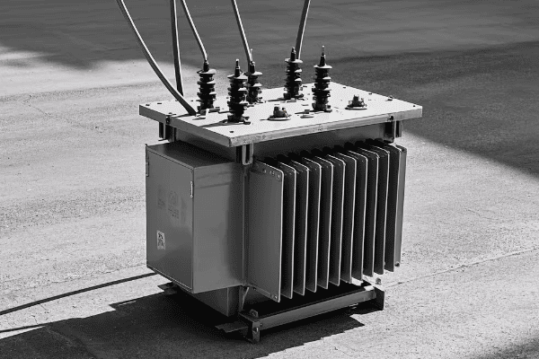
As an electrical engineer with over 15 years of experience in power system design, I’ve seen firsthand how ground transformers can make the difference between a safe, reliable electrical system and a potentially dangerous one. Let’s dive into the world of ground transformers and uncover why they’re so crucial for our electrical safety.
How Does a Ground Transformer Work?
Ever touched a metal appliance and felt a slight tingle? That’s exactly what ground transformers are designed to prevent. But how do they do it?
Ground transformers work by providing a low-impedance path for fault currents to flow to the earth. They create an artificial neutral point in delta-connected systems or reinforce the neutral in wye-connected systems. This ensures that in case of a fault, the current has a safe path to ground, triggering protective devices and minimizing the risk of electric shock.
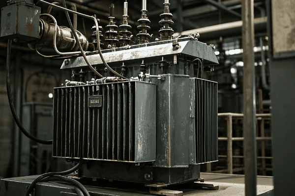
Let’s break down the operation of a ground transformer:
-
Neutral Point Creation: In systems without a neutral (like delta-connected systems), the ground transformer creates an artificial neutral point.
-
Fault Current Path: When a fault occurs, the ground transformer provides a low-resistance path for the fault current to flow to the earth.
-
Voltage Stabilization: By grounding the neutral point, it helps stabilize the phase-to-ground voltages in the system.
-
Protection Triggering: The flow of fault current through the ground transformer can trigger protective devices, isolating the faulty part of the system.
I remember a project where we installed a ground transformer in an old industrial facility. Before the installation, they had frequent issues with equipment malfunctions and occasional minor shocks. After installing the ground transformer, these issues virtually disappeared, and the overall system stability improved significantly.
Key Takeaway: Ground transformers are not just safety devices; they’re crucial for the stable and reliable operation of electrical systems.
What Are the Different Types of Ground Transformers?
Did you know that ground transformers come in various types to suit different environments and applications? Let’s explore the main categories.
Ground transformers are primarily categorized into indoor and outdoor types based on their installation location. Indoor types include hanging and scaffolding ground transformers, while outdoor types are similar to dry-type transformers but with enhanced features for environmental resistance. The choice depends on factors like space constraints, environmental conditions, and system requirements.
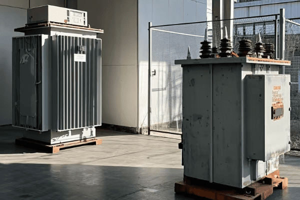
Here’s a closer look at the main types of ground transformers:
-
Indoor Ground Transformers:
- Hanging Type: Suspended from ceilings or structures, ideal for spaces with limited floor area.
- Scaffolding Type: Mounted on scaffolds or platforms, suitable for indoor substations.
-
Outdoor Ground Transformers:
- Similar in shape to dry-type transformers.
- Enhanced features for pollution resistance, insulation, and partial discharge performance.
In a recent project for a coastal industrial plant, we opted for an outdoor ground transformer with special corrosion-resistant coatings. This choice was crucial given the harsh, salty environment, and it has performed exceptionally well over the past three years.
Here’s a comparison table of indoor and outdoor ground transformers:
| Feature | Indoor Ground Transformer | Outdoor Ground Transformer |
|---|---|---|
| Installation | Inside buildings | Outside, exposed to elements |
| Size | Generally smaller | Larger, more robust |
| Environmental Protection | Basic | Enhanced (weather-resistant) |
| Cost | Lower | Higher |
| Maintenance | Easier access | May require special equipment |
| Typical Applications | Office buildings, factories | Substations, industrial plants |
Key Takeaway: Choosing the right type of ground transformer is crucial for ensuring optimal performance and longevity in specific environmental conditions.
Why Are Ground Transformers Critical for Electrical Safety?
Have you ever wondered why electrical accidents aren’t more common, given the amount of power we use daily? Ground transformers play a key role in this safety equation.
Ground transformers are critical for electrical safety because they provide a controlled path for fault currents, prevent dangerous voltage rises on unintended paths, and enable the proper operation of protective devices. They significantly reduce the risk of electric shock, equipment damage, and electrical fires, making them indispensable in modern electrical systems.
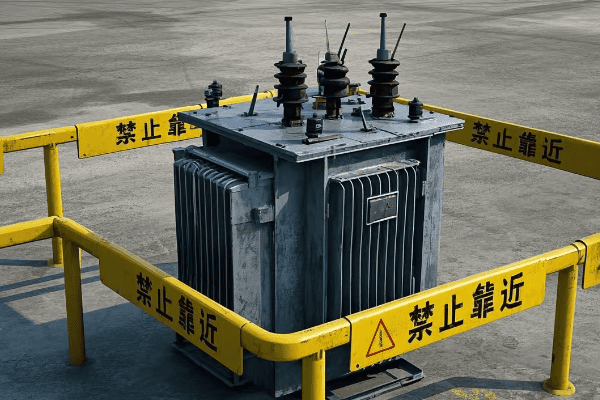
Let’s explore the key safety aspects of ground transformers:
-
Fault Current Management: By providing a low-impedance path to ground, they prevent fault currents from flowing through unintended and potentially dangerous paths.
-
Voltage Stabilization: They help maintain stable phase-to-ground voltages, reducing the risk of insulation failures and equipment damage.
-
Protection System Enablement: Ground transformers allow protective devices like circuit breakers and relays to detect and respond to ground faults quickly.
-
Touch Voltage Reduction: They help limit the voltage that a person might contact during a fault condition, significantly reducing shock hazards.
I once consulted on a case where a small manufacturing plant experienced frequent equipment failures and had a near-miss incident with worker safety. After we installed a properly sized ground transformer, not only did their equipment reliability improve, but they also reported feeling much safer in their work environment.
Key Takeaway: Ground transformers are not just technical components; they’re fundamental safety devices that protect both equipment and human lives in electrical systems.
How to Choose the Right Ground Transformer for Your System?
Selecting the right ground transformer can seem daunting, but it’s crucial for system safety and efficiency. What factors should you consider?
Choosing the right ground transformer involves considering factors such as system voltage, fault current levels, installation environment, and regulatory requirements. Key parameters include the transformer’s kVA rating, impedance, insulation class, and environmental protection level. Proper selection ensures optimal performance, safety, and compliance with electrical codes.
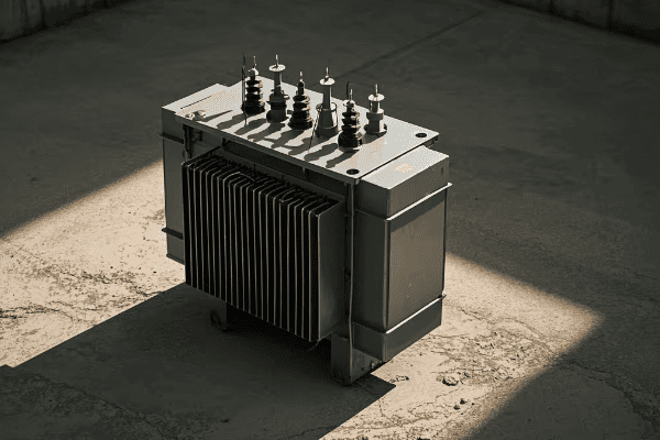
Here’s a step-by-step guide to selecting the right ground transformer:
-
Determine System Requirements:
- Voltage level
- Expected fault current
- Grounding method (solidly grounded, resistance grounded, etc.)
-
Consider Environmental Factors:
- Indoor or outdoor installation
- Temperature range
- Humidity and pollution levels
-
Check Regulatory Compliance:
- Local electrical codes
- Industry-specific standards
-
Evaluate Technical Specifications:
- kVA rating
- Impedance
- Insulation class
- Cooling method
-
Assess Long-term Factors:
- Maintenance requirements
- Expected lifespan
- Future system expansion plans
In my career, I’ve seen many cases where an undersized or improperly specified ground transformer led to system instabilities and safety issues. Always consult with a qualified electrical engineer or the transformer manufacturer to ensure the right selection for your specific needs.
Key Takeaway: Proper selection of a ground transformer is not just about meeting current needs but also about ensuring long-term safety, efficiency, and scalability of your electrical system.
Conclusion
Ground transformers are unsung heroes in our electrical systems, silently working to ensure our safety and the reliability of our power supply. From creating artificial neutral points to managing fault currents, these devices play a crucial role in modern electrical infrastructure. As we continue to rely more heavily on electricity in our daily lives and industries, the importance of properly designed and installed ground transformers cannot be overstated. They are not just technical components but vital safeguards that protect both valuable equipment and, more importantly, human lives.
FAQs: Common Questions About Ground Transformers
- How often should ground transformers be maintained?
Ground transformers should typically be inspected and maintained annually, with more frequent checks in harsh environments. Maintenance includes visual inspections, insulation resistance tests, and oil analysis (for oil-filled types). However, always refer to the manufacturer’s guidelines for specific maintenance schedules.
- Can a system operate without a ground transformer?
While some systems can operate without a ground transformer, it’s generally not recommended due to safety concerns. Ungrounded systems are more prone to transient overvoltages and can be dangerous in fault conditions. Ground transformers provide a crucial safety function that’s hard to replicate with other devices.
- Do ground transformers consume a lot of energy?
Ground transformers typically have very low energy consumption. Their primary purpose is to provide a path for fault currents, not to transform power for regular use. The energy losses in a properly sized ground transformer are minimal compared to the safety benefits they provide.
- Can ground transformers be used in renewable energy systems?
Yes, ground transformers are often used in renewable energy systems, especially in large solar and wind farms. They play a crucial role in ensuring the safe and stable integration of these variable power sources into the grid, helping manage fault currents and maintaining system stability.
- What’s the difference between a ground transformer and a regular power transformer?
While both are transformers, their functions differ significantly. Regular power transformers are used to step voltage up or down for power transmission and distribution. Ground transformers, on the other hand, are specifically designed to provide a ground reference and manage fault currents. They typically don’t change voltage levels in normal operation.
Have you ever stood near a power substation and heard a persistent humming sound? That’s transformer noise, and it’s more complex than you might think.
Transformer noise comes from four main sources: magnetostriction in the core, electromagnetic forces in the windings, cooling fans, and mechanical vibrations. These sources combine to create the characteristic hum we associate with transformers, which can range from 40 to 80 decibels, depending on the transformer’s size and load.

As an electrical engineer with over 15 years of experience in power systems, I’ve encountered numerous noise issues with transformers. Let’s dive into each source of noise and explore why understanding them is crucial for both engineers and the general public.
How Does Magnetostriction Contribute to Transformer Noise?
Ever wondered why a transformer’s hum seems to pulse with the electricity flowing through it? The answer lies in a phenomenon called magnetostriction.
Magnetostriction is a key source of transformer noise, caused by the transformer’s core changing shape slightly as the magnetic field fluctuates. This shape change occurs twice per cycle in the alternating current, creating a vibration that we hear as a humming sound. The noise level increases with higher current levels.
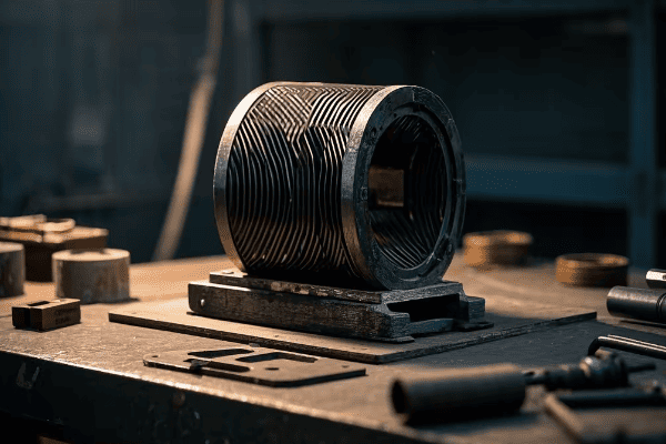
Let’s break down magnetostriction in more detail:
-
Magnetic Field Changes: As alternating current flows through the transformer, the magnetic field in the core changes direction rapidly.
-
Core Material Reaction: The core, typically made of silicon steel, responds to these magnetic changes by expanding and contracting slightly.
-
Vibration Creation: This rapid expansion and contraction creates vibrations in the core material.
-
Sound Production: These vibrations produce the characteristic humming sound we associate with transformers.
I remember working on a project where we were trying to reduce noise in a residential area near a substation. We found that replacing the older transformer cores with newer, more efficiently designed ones reduced the magnetostriction noise by almost 5 decibels. It made a noticeable difference to the local residents.
Key Takeaway: Magnetostriction is an inherent property of magnetic materials and can’t be eliminated entirely, but it can be minimized through careful core design and material selection.
What Role Do Electromagnetic Forces Play in Transformer Noise?
Have you noticed that transformer noise sometimes changes when the power load fluctuates? This is often due to electromagnetic forces at work.
Electromagnetic forces in transformer windings are a significant source of noise. As current flows through the windings, it creates magnetic fields that cause the windings to vibrate. This vibration produces a humming noise that’s typically loudest at the start of operation and decreases as the transformer stabilizes.
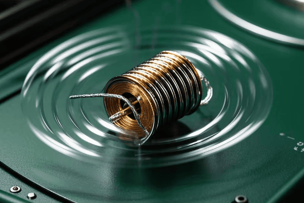
Here’s a closer look at how electromagnetic forces create noise:
-
Current Flow: Electricity flowing through the windings creates a magnetic field.
-
Force Generation: This magnetic field interacts with the current, creating forces that act on the windings.
-
Winding Movement: These forces cause the windings to move slightly, expanding and contracting.
-
Vibration and Sound: The movement of the windings creates vibrations, which we hear as noise.
During a recent factory acceptance test, we observed that the noise level from electromagnetic forces was about 3 decibels higher than expected. We traced it to a slight looseness in the winding clamping system. After tightening the clamps, the noise reduced significantly.
Key Takeaway: Proper winding design and secure clamping are crucial for minimizing noise from electromagnetic forces.
How Do Cooling Fans Contribute to Transformer Noise?
If you’ve ever been near a large transformer on a hot day, you might have noticed an increase in noise. This is often due to the cooling system kicking into high gear.
Cooling fans are a significant source of transformer noise, especially in larger units. These fans are essential for dissipating heat generated during operation, but they can create substantial noise. The sound level typically increases with fan speed, which is adjusted based on the transformer’s temperature.
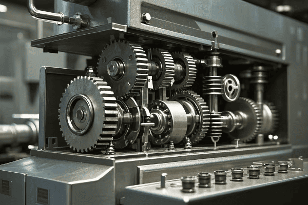
Let’s examine the cooling fan noise in more detail:
-
Heat Generation: Transformers produce heat during operation due to losses in the core and windings.
-
Cooling Necessity: Fans are used to circulate air or oil to remove this heat and prevent overheating.
-
Fan Operation: As the transformer’s load and temperature increase, fans operate at higher speeds.
-
Noise Production: The fan blades moving through air create noise, which increases with fan speed.
I once worked on a project to retrofit an older transformer with a new cooling system. By using larger, slower-spinning fans, we were able to reduce the cooling noise by about 7 decibels while maintaining effective cooling.
Key Takeaway: While cooling fans are necessary for transformer operation, their noise can be minimized through careful design and speed control strategies.
How Do Mechanical Vibrations Contribute to Transformer Noise?
Have you ever felt a slight tremor when standing near a large transformer? That’s mechanical vibration, and it’s more than just a feeling – it’s a source of noise too.
Mechanical vibrations in transformers are caused by the interaction of electromagnetic forces and the physical structure of the transformer. These vibrations can propagate through the transformer tank and supporting structures, creating noise. The intensity of this noise depends on the transformer’s design, mounting, and the surrounding environment.
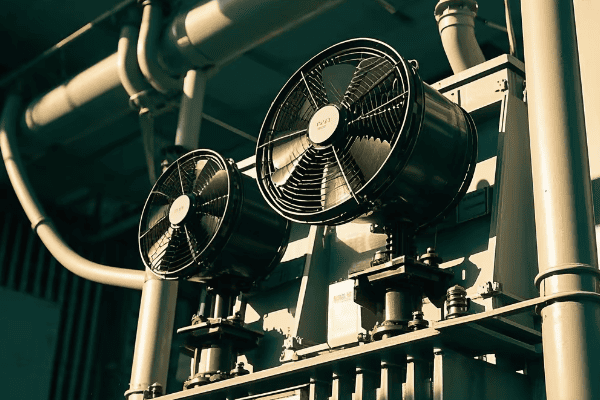
Here’s how mechanical vibrations contribute to noise:
-
Force Origin: Electromagnetic forces in the core and windings create the initial vibrations.
-
Structural Transmission: These vibrations are transmitted through the transformer’s structure.
-
Resonance Effects: Sometimes, the vibration frequency can match the natural frequency of the transformer parts or supporting structures, amplifying the noise.
-
Environmental Factors: The surrounding environment, including the transformer’s mounting and nearby structures, can affect how the vibrations translate into audible noise.
In a recent project, we encountered excessive noise due to mechanical vibrations in a transformer installed on the roof of a building. By adding vibration isolators between the transformer and the building structure, we reduced the noise level inside the building by about 10 decibels.
Key Takeaway: Proper installation, including vibration isolation and structural design, is crucial for minimizing noise from mechanical vibrations.
Conclusion
Understanding the sources of transformer noise is crucial for effective noise management in electrical systems. From the microscopic movements in the core due to magnetostriction to the more obvious noise from cooling fans, each source presents unique challenges and opportunities for noise reduction. By addressing these sources through improved design, materials, and installation practices, we can significantly reduce the impact of transformer noise on both equipment performance and human comfort.
FAQs: Common Questions About Transformer Noise
- Is transformer noise harmful to human health?
While transformer noise is generally not harmful to human health at typical levels, prolonged exposure to high noise levels can cause stress and discomfort. Most transformers produce noise between 40-80 decibels, which is below the 85 decibel threshold considered harmful by occupational health standards. However, in residential areas, even lower noise levels can be disturbing, especially at night.
- How can transformer noise be reduced?
Transformer noise can be reduced through several methods:
- Using high-quality core materials to reduce magnetostriction
- Improving winding design and clamping to minimize electromagnetic vibrations
- Implementing advanced cooling systems with quieter fans
- Using sound enclosures or barriers around transformers
- Proper installation with vibration isolation mounts
In my experience, a combination of these methods can reduce transformer noise by 10-15 decibels or more.
- Do all transformers produce the same amount of noise?
No, noise levels vary significantly between transformers. Factors affecting noise levels include:
- Size and power rating of the transformer
- Design and construction quality
- Age and condition
- Operating load
- Environmental factors
Generally, larger and older transformers tend to be noisier. Modern designs often incorporate noise reduction features.
- Can transformer noise change over time?
Yes, transformer noise can change over time. Common reasons include:
- Loosening of core or winding clamps
- Degradation of insulation materials
- Changes in cooling system performance
- Increased load on the transformer
Regular maintenance and monitoring can help identify and address changes in noise levels before they become significant problems.
- Are there regulations governing transformer noise levels?
Yes, many countries and regions have regulations specifying maximum allowable noise levels for transformers, especially in residential areas. For example, in the United States, NEMA (National Electrical Manufacturers Association) provides guidelines for transformer noise levels. In Europe, the IEC (International Electrotechnical Commission) standards address transformer noise. Always check local regulations when installing or operating transformers.
Have you ever wondered why some transformers look different from others? The secret lies in their winding structures, a crucial aspect of transformer design that often goes unnoticed.
Transformer winding structures are classified into three main categories: based on the number of phases, the number of windings, and the connections between windings. These classifications include single-phase vs. three-phase, single-winding vs. two-winding, and autotransformers vs. isolation transformers. Each type serves specific purposes in power systems.
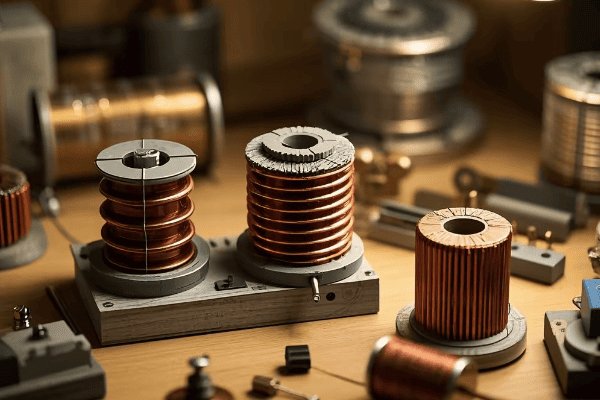
As an electrical engineer with years of experience in power systems, I’ve seen firsthand how the right winding structure can make or break a transformer’s performance. Let’s dive into the fascinating world of transformer windings and uncover why they’re so crucial in our modern electrical grid.
What Are the Different Types of Transformer Winding Structures Based on the Number of Phases?
Have you ever noticed the three large wires running into most industrial buildings? Those are typically for three-phase power, but why do we use different phase configurations in transformers?
Transformers are classified into single-phase, two-phase, and three-phase based on the number of phases. Single-phase transformers have one primary and one secondary winding. Two-phase transformers, now obsolete, had two windings 90 degrees apart. Three-phase transformers, the most common in power systems, have three sets of primary and secondary windings.
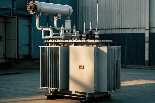
Let’s break down each type:
Single-Phase Transformers
- Structure: One primary and one secondary winding
- Use: Common in residential areas and for small electrical appliances
- Advantage: Simple design, suitable for low power applications
Two-Phase Transformers
- Structure: Two identical windings spaced 90 degrees apart
- Use: Obsolete, replaced by three-phase systems
- Historical note: Once used in early power distribution systems
Three-Phase Transformers
- Structure: Three sets of primary and secondary windings
- Use: Most common in power distribution and industrial applications
- Advantage: Provides constant power supply, more efficient for high power transmission
I remember working on a project to upgrade a small town’s power distribution. We replaced several old single-phase transformers with a new three-phase system. The improvement in power quality and efficiency was remarkable, with fewer voltage fluctuations and reduced energy losses.
Here’s a quick comparison table:
| Type | Number of Windings | Common Applications | Efficiency for High Power |
|---|---|---|---|
| Single-Phase | 2 (1 primary, 1 secondary) | Residential, Small appliances | Lower |
| Two-Phase | 4 (2 sets of primary and secondary) | Obsolete | N/A |
| Three-Phase | 6 (3 sets of primary and secondary) | Industrial, Power distribution | Higher |
Understanding these phase-based classifications is crucial for anyone working with electrical systems. The choice between single-phase and three-phase transformers can significantly impact power quality, efficiency, and the overall performance of an electrical system.
How Do Transformer Winding Structures Differ Based on the Number of Windings?
When you look at a transformer, it might not be immediately obvious how many windings it has. But did you know that the number of windings can tell you a lot about a transformer’s purpose?
Transformers are classified as single-winding or two-winding based on their structure. Single-winding transformers have both primary and secondary on the same core, used mainly for isolation. Two-winding transformers have separate cores for primary and secondary, allowing for voltage transformation. The choice depends on the specific application requirements.

Let’s explore these types in more detail:
Single-Winding Transformers
- Structure: Primary and secondary windings on the same core
- Primary Use: Electrical isolation without voltage change
- Advantages:
- Compact design
- Lower cost
- Efficient for small voltage adjustments
- Applications:
- Power line carrier communication
- Some types of voltage regulators
Two-Winding Transformers
- Structure: Separate cores for primary and secondary windings
- Primary Use: Voltage transformation and isolation
- Advantages:
- Greater flexibility in voltage ratios
- Better isolation between primary and secondary
- Suitable for large voltage transformations
- Applications:
- Power distribution transformers
- Isolation transformers in sensitive electronic equipment
I once worked on a project in a hospital where we needed to protect sensitive medical equipment from power line disturbances. We chose a two-winding isolation transformer because it provided both the necessary voltage adjustment and excellent electrical isolation, ensuring the safety and accuracy of the medical devices.
Here’s a comparison table to summarize the key differences:
| Aspect | Single-Winding Transformer | Two-Winding Transformer |
|---|---|---|
| Core Structure | Shared core | Separate cores |
| Main Function | Isolation | Voltage transformation and isolation |
| Efficiency for Small Voltage Changes | Higher | Lower |
| Isolation Quality | Good | Excellent |
| Typical Applications | Voltage regulation, Line conditioning | Power distribution, Equipment protection |
| Cost | Lower | Higher |
Understanding these differences is crucial when selecting transformers for specific applications. The choice between single-winding and two-winding transformers can impact not only the performance of your electrical system but also its safety and reliability.
How Do Connections Between Windings Affect Transformer Classification?
Have you ever wondered why some transformers can change voltage so efficiently while others provide better isolation? The secret lies in how their windings are connected.
Transformers are classified as autotransformers or isolation transformers based on the connections between their windings. Autotransformers have electrically connected primary and secondary windings, sharing a common portion. Isolation transformers have completely separate primary and secondary windings, providing electrical isolation. Each type has unique advantages for specific applications.
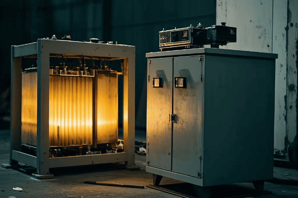
Let’s examine these two types in detail:
Autotransformers
- Structure: Primary and secondary windings are electrically connected
- Primary Use: Efficient voltage adjustment with a small transformation ratio
- Advantages:
- Higher efficiency for small voltage changes
- Smaller size and lower cost
- Less copper required in construction
- Applications:
- Voltage regulators in power systems
- Motor starting applications
- Interconnecting systems with slightly different voltages
Isolation Transformers
- Structure: Primary and secondary windings are electrically isolated
- Primary Use: Providing galvanic isolation between circuits
- Advantages:
- Complete electrical separation between primary and secondary
- Protection against electric shock and ground faults
- Reduction of electrical noise and interference
- Applications:
- Medical equipment
- Sensitive electronic devices
- Safety-critical industrial processes
I recall a project at a manufacturing plant where we needed to connect two systems operating at slightly different voltages. We used an autotransformer because it provided the necessary voltage adjustment efficiently and cost-effectively. However, for the plant’s control room equipment, we installed isolation transformers to protect against electrical noise and potential ground faults.
Here’s a comparison table highlighting the key differences:
| Aspect | Autotransformer | Isolation Transformer |
|---|---|---|
| Winding Connection | Electrically connected | Electrically isolated |
| Primary Function | Efficient voltage adjustment | Electrical isolation |
| Size and Cost | Smaller and less expensive | Larger and more expensive |
| Efficiency for Small Voltage Changes | Very high | Lower |
| Safety in High Voltage Applications | Lower (no isolation) | Higher (complete isolation) |
| Typical Applications | Voltage regulation, Motor starting | Medical equipment, Sensitive electronics |
The choice between autotransformers and isolation transformers depends on the specific requirements of your application. While autotransformers offer efficiency and cost savings for small voltage adjustments, isolation transformers provide crucial safety and noise reduction features for sensitive or critical equipment.
Conclusion
Transformer winding structures play a crucial role in power systems, affecting efficiency, safety, and functionality. By understanding the classifications based on phases, number of windings, and connections, engineers and technicians can make informed decisions in designing and maintaining electrical systems. Whether you’re working with residential power supplies or industrial equipment, the right transformer winding structure can make all the difference in ensuring reliable, efficient, and safe power distribution.
FAQs: Common Questions About Transformer Winding Structures
- Why are three-phase transformers more common in power distribution?
Three-phase transformers are more common in power distribution for several reasons:
- Efficiency: They provide a more constant and balanced power flow, resulting in higher efficiency in power transmission and distribution.
- Cost-effectiveness: One three-phase transformer is generally cheaper and requires less space than three single-phase transformers of equivalent power rating.
- Power density: Three-phase systems can transmit more power with less conductor material compared to single-phase systems.
- Smooth power delivery: They provide a smoother power delivery for large motors and industrial equipment, reducing vibration and wear.
In my experience, upgrading from single-phase to three-phase systems in industrial areas has consistently led to improved power quality and reduced energy losses. However, single-phase transformers still have their place in residential areas and for smaller loads.
- Can a single-winding transformer be used for voltage transformation?
Yes, a single-winding transformer can be used for voltage transformation, but with limitations:
- Autotransformer configuration: Single-winding transformers used for voltage transformation are typically configured as autotransformers.
- Limited range: They are most efficient and practical for small voltage adjustments, usually within a ratio of 2:1 or less.
- No isolation: Unlike two-winding transformers, they don’t provide electrical isolation between input and output.
- Applications: Common uses include voltage regulators, motor starters, and interconnecting systems with slight voltage differences.
I once worked on a project where we used a single-winding autotransformer to adjust the voltage in a small industrial facility. It was perfect for our needs because we only needed a 10% voltage boost and isolation wasn’t a concern. However, for larger voltage changes or where isolation is required, a two-winding transformer would be the better choice.
- What are the safety advantages of isolation transformers?
Isolation transformers offer several important safety advantages:
- Electrical isolation: They provide complete galvanic isolation between primary and secondary circuits, preventing the transfer of DC voltages and fault currents.
- Ground fault protection: They can break ground loops and provide protection against electric shock from ground faults.
- Noise reduction: They attenuate common-mode noise and transients, protecting sensitive equipment.
- Voltage stabilization: Some isolation transformers include voltage regulation features, providing stable output voltage.
In a hospital project I worked on, we installed isolation transformers for all critical medical equipment. This not only protected the equipment from power line disturbances but also enhanced patient safety by reducing the risk of electric shock. The investment in isolation transformers paid off in terms of equipment longevity and reliability.
- How do autotransformers differ from regular transformers in terms of efficiency?
Autotransformers generally offer higher efficiency compared to regular (two-winding) transformers, especially for small voltage transformations:
- Reduced losses: Only a portion of the power is transformed, resulting in lower copper losses.
- Size and cost: They are smaller and use less material, which can lead to cost savings.
- Limitation: The efficiency advantage diminishes as the voltage transformation ratio increases.
For example, in a project where we needed to adjust voltage by just 10%, an autotransformer was about 99% efficient, compared to about 97% for a comparable two-winding transformer. However, for large voltage changes or where isolation is needed, regular transformers are often the better choice despite slightly lower efficiency.
- Are there any special maintenance considerations for different winding structures?
Yes, different winding structures have specific maintenance considerations:
- Three-phase transformers: Require balanced load monitoring and phase-to-phase insulation checks.
- Autotransformers: Need careful monitoring of the common winding for signs of overheating or insulation breakdown.
- Isolation transformers: Regular testing of insulation resistance between primary and secondary windings is crucial.
- All types: Require routine oil analysis (for oil-filled types), thermal imaging, and power quality measurements.
In my maintenance experience, I’ve found that autotransformers often require more frequent inspections due to their compact design and shared windings. For isolation transformers, we pay extra attention to maintaining the integrity of the isolation barrier. Regular maintenance tailored to each type of winding structure is key to ensuring long-term reliability and safety of transformer installations.
Have you ever wondered why those green boxes are popping up in your neighborhood? They’re not just for decoration – they’re changing the game in electrical distribution.
Pad mount transformers offer significant advantages in modern electrical systems, including enhanced safety, space efficiency, aesthetic appeal, improved reliability, easy maintenance, environmental protection, and cost-effectiveness. These benefits make them ideal for urban and suburban power distribution needs.
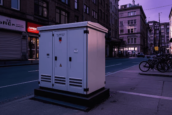
As someone who’s been in the electrical industry for years, I’ve seen firsthand how pad mount transformers are revolutionizing our power systems. Let’s dive into the key advantages that make these transformers a game-changer in modern electrical infrastructure.
What Are Pad Mount Transformers? A Quick Introduction
Ever noticed those green metal boxes in your neighborhood? They’re not just random utility equipment – they’re the unsung heroes of our modern power grid.
Pad mount transformers are ground-level electrical distribution transformers enclosed in a locked steel cabinet. They convert high-voltage electricity from power lines to lower voltages suitable for homes and businesses, offering a safer and more aesthetically pleasing alternative to traditional pole-mounted transformers.
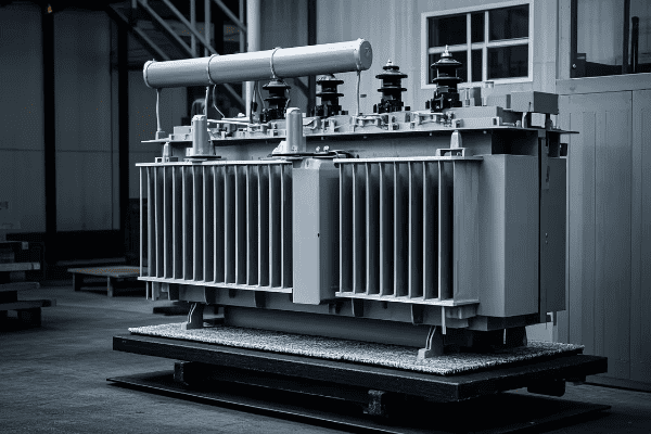
Let’s break down the key components and features of pad mount transformers:
Core Components
-
Transformer Core and Windings
- Heart of the transformer
- Converts voltage levels
-
Insulating Oil
- Cools and insulates internal components
- Improves efficiency and longevity
-
Steel Cabinet
- Protects internal components
- Provides safety barrier
-
High and Low Voltage Bushings
- Connect transformer to power lines and distribution cables
Key Features
-
Ground-Level Installation
- Easy access for maintenance
- No need for poles or overhead lines
-
Compact Design
- Fits in smaller spaces
- Ideal for urban and suburban areas
-
Tamper-Resistant Enclosure
- Locked cabinet prevents unauthorized access
- Enhances public safety
-
Customizable Appearance
- Can be painted or designed to blend with surroundings
- Minimizes visual impact
I remember my first encounter with a pad mount transformer during a residential development project. I was amazed at how such a powerful piece of equipment could be so discreetly integrated into the landscape. It was a far cry from the bulky pole-mounted transformers I was used to seeing.
Here’s a quick comparison table between pad mount and traditional pole mount transformers:
| Feature | Pad Mount | Pole Mount |
|---|---|---|
| Installation | Ground level | Elevated on poles |
| Accessibility | Easy | Requires climbing or lift |
| Visual Impact | Low | High |
| Safety | High (enclosed) | Moderate (exposed) |
| Space Efficiency | High | Low |
| Customization | Flexible | Limited |
| Maintenance | Simpler | More complex |
Pad mount transformers are not just about looks, though. Their design offers numerous practical advantages that we’ll explore in detail. From enhanced safety to improved reliability, these transformers are changing the way we think about power distribution in modern settings.
Enhanced Safety: How Pad Mount Transformers Reduce Electrical Hazards
Safety is paramount in electrical systems. But have you ever worried about the exposed transformers on poles in your neighborhood? Pad mount transformers offer a solution that puts those concerns to rest.
Pad mount transformers significantly reduce electrical hazards through their enclosed design, tamper-resistant features, and ground-level installation. This configuration minimizes the risk of accidental contact, vandalism, and weather-related incidents, making them a safer option for urban and residential areas.
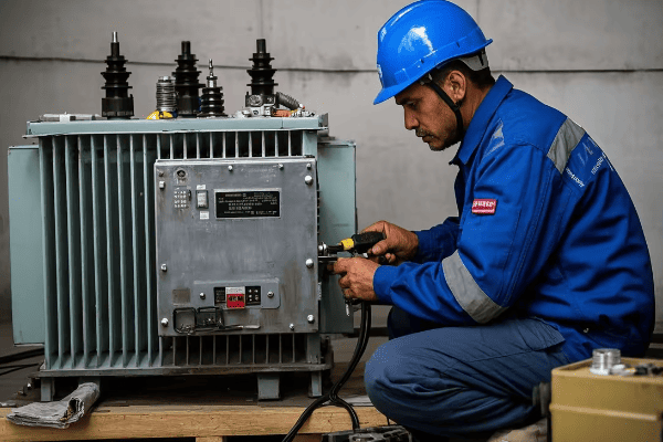
Let’s dive deeper into the safety features that make pad mount transformers stand out:
1. Enclosed Design
The most obvious safety feature of pad mount transformers is their fully enclosed cabinet. This design offers multiple safety benefits:
- Protection from Elements: The cabinet shields the transformer from rain, snow, and debris, reducing the risk of weather-related malfunctions.
- Animal Protection: It prevents animals from coming into contact with live components, which is a common issue with pole-mounted transformers.
- Vandalism Deterrent: The solid enclosure makes it difficult for vandals to access or damage critical components.
2. Tamper-Resistant Features
Pad mount transformers are designed with security in mind:
- Locked Access: The cabinet is equipped with locks that only authorized personnel can open.
- Warning Labels: Clear warning signs deter unauthorized access attempts.
- Concealed Connections: High-voltage connections are hidden from view, reducing temptation for tampering.
3. Ground-Level Installation
Installing transformers at ground level offers several safety advantages:
- No Climbing Required: Maintenance can be performed without the need for bucket trucks or climbing, reducing worker risk.
- Stability: Ground-level installation means less risk of falling during storms or accidents.
- Quick Access in Emergencies: First responders can easily access the transformer if needed.
4. Improved Grounding
Pad mount transformers often have superior grounding systems:
- Direct Earth Connection: The pad provides an excellent grounding surface.
- Multiple Grounding Points: This ensures better protection against electrical faults.
5. Arc Flash Protection
Modern pad mount transformers incorporate advanced arc flash protection:
- Containment: The enclosed design helps contain potential arc flashes.
- Pressure Relief: Many models include pressure relief devices to safely vent in case of an internal fault.
Here’s a comparison of safety features between pad mount and pole mount transformers:
| Safety Feature | Pad Mount | Pole Mount |
|---|---|---|
| Enclosed Design | Yes | No |
| Tamper Resistance | High | Low |
| Ground-Level Access | Yes | No |
| Weather Protection | High | Low |
| Animal Contact Prevention | High | Low |
| Arc Flash Containment | Yes | Limited |
| Grounding Efficiency | High | Moderate |
| Public Exposure Risk | Low | High |
I recall a project where we replaced old pole-mounted transformers with pad mount units in a residential area prone to storms. The following year, during a severe thunderstorm, while many pole-mounted transformers in neighboring areas failed, our pad mount transformers remained operational and safe. This not only prevented power outages but also eliminated the safety risks associated with downed power lines.
The enhanced safety of pad mount transformers extends beyond just the equipment itself. It also improves the overall safety of the surrounding area:
- Reduced Climbing Hazards: Eliminates the temptation for children to climb poles.
- Clearer Sightlines: No poles means better visibility for drivers and pedestrians.
- Fewer Overhead Lines: Reduces risks associated with fallen power lines during storms.
In urban planning, the safety benefits of pad mount transformers are becoming increasingly recognized. Many cities now prefer or even mandate their use in new developments, especially in residential areas and near schools or parks.
While no electrical equipment is 100% risk-free, pad mount transformers represent a significant step forward in electrical safety. Their design addresses many of the vulnerabilities associated with traditional pole-mounted transformers, making them an excellent choice for modern, safety-conscious electrical systems.
Space Efficiency: Maximizing Land Use with Compact Pad Mount Designs
In today’s urban landscapes, every square foot counts. Have you ever wondered how we can power our growing cities without cluttering our streets with bulky electrical equipment? The answer lies in the compact design of pad mount transformers.
Pad mount transformers maximize land use efficiency through their compact, ground-level design. They eliminate the need for large overhead structures and can be easily integrated into landscaping or existing structures. This space-saving feature is crucial in dense urban areas and modern residential developments.
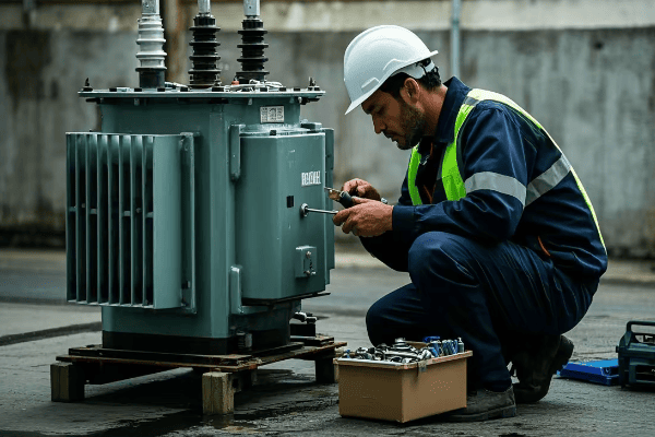
Let’s explore how pad mount transformers contribute to space efficiency:
1. Compact Footprint
Pad mount transformers are designed to be as compact as possible:
- Smaller Ground Area: They typically require less than 10 square feet of ground space.
- Vertical Space Savings: By eliminating the need for poles, they free up valuable airspace.
- Flexible Placement: Can be installed close to buildings or property lines.
2. Underground Connections
One of the key space-saving features is the use of underground connections:
- No Overhead Lines: Eliminates the need for unsightly and space-consuming overhead wires.
- Reduced Clearance Requirements: Without overhead lines, there’s no need for large clearance areas around the transformer.
- Streamlined Appearance: Creates a cleaner, more organized look in urban and suburban areas.
3. Integration with Surroundings
Pad mount transformers can be creatively integrated into their environment:
- Landscaping: Can be surrounded by shrubs or incorporated into garden designs.
- Structural Integration: Some designs allow for integration into walls or building foundations.
- Multi-Use Spaces: The area above and around the transformer can often be utilized for other purposes.
4. Scalability
The compact design of pad mount transformers allows for easy scaling of electrical infrastructure:
- Modular Installation: Multiple units can be installed side by side for higher capacity needs.
- Easy Upgrades: Replacing or upgrading units is simpler and less disruptive than with pole-mounted systems.
Here’s a comparison of space utilization between pad mount and pole mount transformers:
| Aspect | Pad Mount | Pole Mount |
|---|---|---|
| Ground Footprint | Small (< 10 sq ft) | Larger (pole base + clearance) |
| Vertical Space Use | Minimal | Significant |
| Overhead Line Requirement | None | Extensive |
| Landscaping Compatibility | High | Low |
| Urban Integration | Easy | Challenging |
| Scalability | High | Limited |
| Multi-Use Space Potential | Yes | No |
I once worked on a project to revitalize a dense urban neighborhood. The city wanted to increase power capacity without sacrificing valuable real estate. By switching to pad mount transformers, we were able to triple the electrical capacity while actually reducing the visible footprint of the electrical infrastructure. This freed up space for wider sidewalks and small pocket parks, greatly enhancing the neighborhood’s livability.
The space efficiency of pad mount transformers offers several additional benefits:
- Improved Property Values: By freeing up space and improving aesthetics, they can positively impact property values.
- Enhanced Urban Planning: Allows for more flexible and creative urban design solutions.
- Reduced Right-of-Way Requirements: Simplifies the process of obtaining permissions for new installations.
In modern urban development, the space-saving qualities of pad mount transformers are becoming increasingly valuable. As cities grow denser and land becomes more precious, the ability to provide robust electrical infrastructure without consuming large amounts of space is crucial.
Pad mount transformers represent a smart solution for balancing the growing power needs of urban areas with the desire for open, uncluttered spaces. Their compact design not only saves space but also opens up new possibilities for urban planning and development.
Aesthetic Appeal: Integrating Pad Mount Transformers into Urban Landscapes
Have you ever noticed how some neighborhoods seem cleaner and more visually appealing than others? The secret might lie in how they handle their electrical infrastructure, particularly with the use of pad mount transformers.
Pad mount transformers offer significant aesthetic advantages over traditional pole-mounted units. Their low profile and customizable enclosures allow for seamless integration into urban and suburban landscapes. This aesthetic flexibility helps maintain the visual appeal of neighborhoods while providing essential electrical infrastructure.

Let’s explore how pad mount transformers contribute to the aesthetic appeal of urban environments:
1. Low Visual Profile
One of the most immediate aesthetic benefits of pad mount transformers is their low visual profile:
- Height Reduction: Typically standing only 4-5 feet tall, much lower than pole-mounted alternatives.
- Reduced Skyline Clutter: Eliminates the need for overhead wires and poles that can obstruct views.
- Ground-Level Integration: Can be easily incorporated into ground-level landscaping designs.
2. Customizable Appearance
Pad mount transformers offer a high degree of customization to match their surroundings:
- Color Options: Enclosures can be painted to blend with the environment or match architectural styles.
- Textured Finishes: Available in various textures to complement different settings (e.g., brick, stone, or wood grain).
- Artistic Designs: Some communities use transformer enclosures as canvases for public art or murals.
3. Landscaping Integration
The design of pad mount transformers allows for creative landscaping solutions:
- Shrub Screening: Can be surrounded by appropriate vegetation for natural concealment.
- Hardscape Elements: Incorporation into retaining walls, fences, or other structural elements.
- Garden Features: Some designs allow transformers to double as planters or garden structures.
4. Architectural Harmony
Pad mount transformers can be designed to complement local architecture:
- Style Matching: Enclosures can mimic architectural features of surrounding buildings.
- Historical Preservation: In historic districts, designs can be tailored to maintain period aesthetics.
- Modern Integration: Sleek designs can enhance contemporary urban landscapes.
Here’s a comparison of aesthetic features between pad mount and pole mount transformers:
| Aesthetic Aspect | Pad Mount | Pole Mount |
|---|---|---|
| Visual Impact | Low | High |
| Customization Options | Extensive | Limited |
| Landscaping Compatibility | High | Low |
| Architectural Integration | Easy | Difficult |
| Skyline Impact | Minimal | Significant |
| Potential for Artistic Use | High | Low |
| Historical Area Suitability | Adaptable | Often Incompatible |
I remember a project in a historic downtown area where the local preservation society was initially against any new electrical infrastructure. We proposed pad mount transformers designed to look like vintage street furniture, complete with period-appropriate paint and detailing. Not only did this solution meet the area’s power needs, but it also enhanced the historic charm of the neighborhood. The transformers became talking points for tourists, blending utility with historical aesthetics.
The aesthetic benefits of pad mount transformers extend beyond just looks:
- Increased Property Values: Improved aesthetics can positively impact real estate values in the area.
- Community Pride: Well-designed infrastructure can contribute to a sense of community pride and care.
- Tourism Potential: In some cases, creatively designed transformers can become minor local attractions.
In urban planning and development, the aesthetic appeal of electrical infrastructure is becoming increasingly important. As cities strive to create more livable, attractive spaces, the ability to provide essential services without visual disruption is crucial.
Pad mount transformers represent a perfect blend of function and form in modern urban design. They prove that necessary infrastructure doesn’t have to be an eyesore. Instead, with thoughtful design and integration, these transformers can actually enhance the visual appeal of our urban and suburban landscapes.
By choosing pad mount transformers, communities can maintain their aesthetic integrity while still meeting growing power needs. It’s a win-win solution that keeps our cities both beautiful and powered for the future.
Improved Reliability: Weather Resistance of Pad Mount Transformers
Have you ever experienced a power outage during a storm and wondered why? The answer often lies in how well our electrical equipment can withstand the elements. This is where pad mount transformers shine.
Pad mount transformers offer improved reliability through enhanced weather resistance. Their sealed, ground-level design protects critical components from rain, snow, ice, and wind. This results in fewer weather-related outages and longer operational life compared to traditional pole-mounted transformers.

Let’s explore how pad mount transformers stand up to various weather conditions:
1. Protection Against Rain and Flooding
Pad mount transformers are designed with water resistance in mind:
- Sealed Enclosures: Prevent water ingress during heavy rains.
- Elevated Pads: Often installed on slightly raised concrete pads to avoid ground-level flooding.
- Water-Resistant Seals: High-quality seals around doors and cable entries keep moisture out.
2. Snow and Ice Resistance
In colder climates, pad mount transformers have several advantages:
- Reduced Ice Buildup: The lack of overhead components means less surface area for ice accumulation.
- Heat Generation: Internal heat helps prevent snow and ice buildup around the unit.
- Easy Snow Removal: Ground-level installation allows for easier clearing of snow around the transformer.
3. Wind Resistance
High winds pose less of a threat to pad mount transformers:
- Low Profile: Presents less surface area to wind, reducing the risk of damage.
- Sturdy Construction: Heavy-duty enclosures are designed to withstand high wind speeds.
- No Overhead Lines: Eliminates the risk of wind-related line damage common with pole-mounted transformers.
4. Lightning Protection
While no electrical equipment is completely immune to lightning, pad mount transformers offer some advantages:
- Grounding Systems: Often have more comprehensive grounding than pole-mounted units.
- Surge Arresters: Equipped with devices to divert lightning-induced surges.
- Enclosed Design: Provides an additional layer of protection for internal components.
5. Temperature Extremes
Pad mount transformers are designed to operate in a wide range of temperatures:
- Insulated Cabinets: Help maintain stable internal temperatures in both hot and cold climates.
- Cooling Systems: Many models include advanced cooling systems for high-temperature environments.
- Cold Weather Operation: Less exposed to extreme cold compared to pole-mounted units.
Here’s a comparison of weather resistance features between pad mount and pole mount transformers:
| Weather Factor | Pad Mount | Pole Mount |
|---|---|---|
| Rain Protection | Excellent | Moderate |
| Flood Resistance | Good (if elevated) | Better (naturally elevated) |
| Snow/Ice Buildup | Minimal | Significant |
| Wind Resistance | High | Moderate |
| Lightning Protection | Good | Moderate |
| Extreme Temperature Performance | Better | Variable |
| Overall Weather-Related Reliability | Higher | Lower |
I recall a project in a coastal area prone to hurricanes. We replaced the old pole-mounted transformers with pad mount units. The following year, when a Category 3 hurricane hit, the pad mount transformers remained operational throughout the storm, while many pole-mounted units in neighboring areas failed. This not only kept the lights on for residents but also significantly reduced post-storm recovery time and costs.
The improved weather resistance of pad mount transformers offers several additional benefits:
- Reduced Maintenance Costs: Less weather-related damage means lower long-term maintenance expenses.
- Improved Power Quality: Fewer weather-induced fluctuations lead to more stable power supply.
- Longer Lifespan: Protection from the elements contributes to an extended operational life.
In areas with challenging weather conditions, the reliability of pad mount transformers becomes even more crucial. They play a vital role in ensuring consistent power supply during extreme weather events, which is increasingly important in our climate-changing world.
For utility companies and city planners, the weather resistance of pad mount transformers translates to:
- Fewer Customer Complaints: Reduced outages lead to higher customer satisfaction.
- Lower Emergency Response Costs: Fewer weather-related failures mean less need for emergency repairs.
- Improved Grid Resilience: A more weather-resistant infrastructure enhances overall grid stability.
In conclusion, the superior weather resistance of pad mount transformers is not just about keeping the lights on during a storm. It’s about building a more resilient, reliable electrical infrastructure that can withstand the challenges of our changing climate while providing consistent service to communities.
Easy Maintenance: Accessibility Features of Pad Mount Transformers
Have you ever wondered why some power outages seem to last longer than others? Often, it comes down to how easily technicians can access and maintain the electrical equipment. This is where pad mount transformers really shine.
Pad mount transformers offer superior accessibility for maintenance compared to traditional pole-mounted units. Their ground-level installation allows for easier inspection, servicing, and repair. This accessibility not only reduces maintenance time and costs but also improves overall system reliability through more frequent and thorough checks.

Let’s explore the key accessibility features that make pad mount transformers a maintenance-friendly option:
1. Ground-Level Access
The most obvious advantage of pad mount transformers is their ground-level installation:
- No Climbing Required: Eliminates the need for bucket trucks or climbing gear.
- Safer Working Conditions: Reduces the risk of falls and other height-related accidents.
- All-Weather Access: Easier to perform maintenance in various weather conditions.
2. Hinged Cabinet Doors
Most pad mount transformers feature well-designed access points:
- Wide-Opening Doors: Allow technicians to easily reach all components.
- Secure Locking Mechanisms: Provide quick access for authorized personnel while ensuring security.
- Weather-Resistant Seals: Maintain the integrity of the enclosure when closed.
3. Modular Design
Many modern pad mount transformers are built with a modular approach:
- Replaceable Components: Allow for quick swapping of faulty parts.
- Standardized Layouts: Consistent designs across models for easier familiarization and maintenance.
- Upgradeable Systems: Easier to upgrade or add new features without replacing the entire unit.
4. Built-in Diagnostic Features
Advanced pad mount transformers often include diagnostic capabilities:
- Monitoring Systems: Built-in sensors for real-time performance tracking.
- Visible Gauges: Easy-to-read indicators for oil levels, temperature, and pressure.
- Test Points: Accessible points for connecting diagnostic equipment.
5. Spacious Work Area
The design of pad mount transformers often includes considerations for maintenance work:
- Ample Internal Space: Room for technicians to work comfortably inside the cabinet.
- External Working Surface: Some models include a fold-down platform for tools and equipment.
- Good Lighting: Either through transparent panels or built-in lighting systems.
Here’s a comparison of maintenance accessibility between pad mount and pole mount transformers:
| Accessibility Feature | Pad Mount | Pole Mount |
|---|---|---|
| Ground-Level Access | Yes | No |
| Need for Specialized Equipment | Minimal | Extensive (bucket trucks, etc.) |
| Ease of Component Replacement | High | Moderate to Low |
| Safety During Maintenance | High | Moderate (height risks) |
| All-Weather Maintenance Capability | High | Limited |
| Diagnostic Feature Accessibility | Easy | Often Challenging |
| Space for Maintenance Work | Ample | Limited |
I remember a project where we upgraded an industrial park from pole-mounted to pad mount transformers. The maintenance team was initially skeptical about the change. However, after just a few months, they reported a 40% reduction in maintenance time and a significant improvement in their ability to perform thorough inspections. This not only saved costs but also allowed them to catch and prevent several potential issues before they became major problems.
The easy maintenance of pad mount transformers brings several additional benefits:
- Reduced Downtime: Quicker maintenance means shorter outages during repairs.
- Improved Preventive Maintenance: Easier access encourages more regular check-ups.
- Lower Labor Costs: Less time and fewer personnel required for routine maintenance.
- Enhanced Safety: Reduced risk of accidents during maintenance procedures.
For utility companies and facility managers, the accessibility of pad mount transformers translates to:
- More Efficient Resource Allocation: Maintenance teams can service more units in less time.
- Improved Asset Longevity: Regular, thorough maintenance extends the life of the equipment.
- Better Emergency Response: Faster access and repairs during critical situations.
In the broader context of electrical infrastructure management, the easy maintenance of pad mount transformers contributes to:
- Higher System Reliability: Regular maintenance leads to fewer unexpected failures.
- Increased Customer Satisfaction: Fewer and shorter outages improve service quality.
- Cost-Effective Operations: Lower long-term maintenance costs benefit both providers and consumers.
In conclusion, the accessibility features of pad mount transformers represent a significant advancement in electrical infrastructure maintenance. By making it easier, safer, and more efficient to maintain these critical components, pad mount transformers help ensure a more reliable and resilient power distribution system for our communities.
Environmental Protection: Minimizing Ecological Impact with Pad Mount Systems
In today’s world, environmental concerns are at the forefront of many industries. But have you ever considered the ecological impact of the transformers that power our homes and businesses? Pad mount transformers offer a greener alternative that’s worth exploring.
Pad mount transformers contribute to environmental protection by minimizing land use, reducing the risk of oil spills, and decreasing the impact on wildlife. Their compact, sealed design and integration with underground systems result in less habitat disruption and lower electromagnetic field emissions compared to traditional pole-mounted transformers.
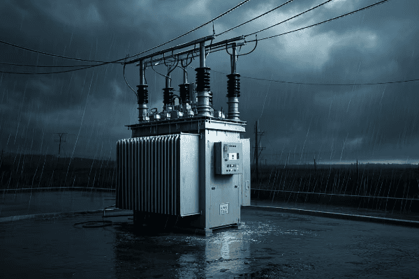
Let’s delve into the environmental benefits of pad mount transformers:
1. Reduced Land Use
Pad mount transformers have a smaller ecological footprint:
- Compact Design: Requires less cleared land than pole-mounted systems.
- Underground Cabling: Eliminates the need for overhead lines, preserving trees and natural landscapes.
- Integration with Existing Structures: Can be incorporated into buildings or urban landscapes, minimizing additional land use.
2. Minimized Oil Spill Risk
Modern pad mount transformers are designed with environmental safety in mind:
- Sealed Containment: Robust enclosures significantly reduce the risk of oil leaks.
- Secondary Containment: Many models include built-in oil catchment systems.
- Leak Detection Systems: Advanced units feature early warning systems for potential leaks.
3. Wildlife Protection
The design of pad mount transformers helps protect local wildlife:
- No Overhead Lines: Reduces risks to birds and other animals that might collide with or be electrocuted by overhead wires.
- Enclosed Design: Prevents animals from accessing dangerous components.
- Reduced Habitat Disruption: Smaller footprint means less impact on natural habitats.
4. Lower Electromagnetic Field (EMF) Emissions
Pad mount transformers often have lower EMF emissions:
- Shielded Design: Metal enclosures provide natural EMF shielding.
- Ground-Level Placement: EMF strength decreases rapidly with distance, so ground-level placement reduces human exposure.
- Advanced Designs: Some models incorporate additional EMF reduction technologies.
5. Energy Efficiency
Many pad mount transformers are designed for improved energy efficiency:
- Advanced Materials: Use of high-efficiency core materials reduces energy losses.
- Better Cooling Systems: More efficient cooling leads to lower energy waste.
- Smart Grid Compatibility: Easier integration with smart grid systems for optimized power distribution.
Here’s a comparison of environmental factors between pad mount and pole mount transformers:
| Environmental Factor | Pad Mount | Pole Mount |
|---|---|---|
| Land Use | Minimal | Moderate to High |
| Tree Preservation | High | Low to Moderate |
| Oil Spill Risk | Low | Moderate |
| Wildlife Impact | Low | Moderate to High |
| EMF Emissions | Lower | Higher |
| Visual Pollution | Low | High |
| Energy Efficiency | Generally Higher | Variable |
I once worked on a project in a sensitive ecological area near a wetland. The local environmental agency was concerned about the impact of new electrical infrastructure on the ecosystem. By using pad mount transformers with advanced oil containment systems and underground cabling, we were able to minimize the ecological footprint. The project not only met the power needs of the community but also preserved the natural habitat, earning praise from local environmental groups.
The environmental benefits of pad mount transformers extend beyond their immediate surroundings:
- Reduced Carbon Footprint: Lower energy losses and longer lifespan contribute to reduced overall carbon emissions.
- Sustainable Urban Development: Allows for greener urban planning and more efficient land use.
- Noise Pollution Reduction: Quieter operation compared to some pole-mounted units.
For utility companies and urban planners, the environmental advantages of pad mount transformers align with growing sustainability goals:
- Compliance with Environmental Regulations: Easier to meet stringent environmental standards.
- Green Image: Contributes to a more environmentally friendly corporate or municipal image.
- Long-term Sustainability: Supports the development of more sustainable power distribution systems.
In the broader context of environmental protection, pad mount transformers play a crucial role in:
- Biodiversity Conservation: Less habitat disruption helps maintain local ecosystems.
- Urban Greening Initiatives: Compatibility with green spaces and urban forests.
- Climate Change Mitigation: Energy efficiency and reduced land use contribute to overall climate goals.
In conclusion, pad mount transformers represent a more environmentally friendly approach to power distribution. By minimizing ecological impact while meeting our growing energy needs, these transformers are an essential component in building a more sustainable electrical infrastructure for the future.
Cost-Effectiveness: Long-Term Savings of Pad Mount Transformer Installations
When it comes to electrical infrastructure, the initial price tag doesn’t tell the whole story. Have you ever wondered why some utilities are switching to pad mount transformers despite their higher upfront costs? The answer lies in their long-term cost-effectiveness.
Pad mount transformers offer significant long-term cost savings compared to traditional pole-mounted units. While initial installation costs may be higher, their lower maintenance requirements, longer lifespan, and reduced energy losses result in substantial savings over time. This makes them a cost-effective choice for modern power distribution systems.
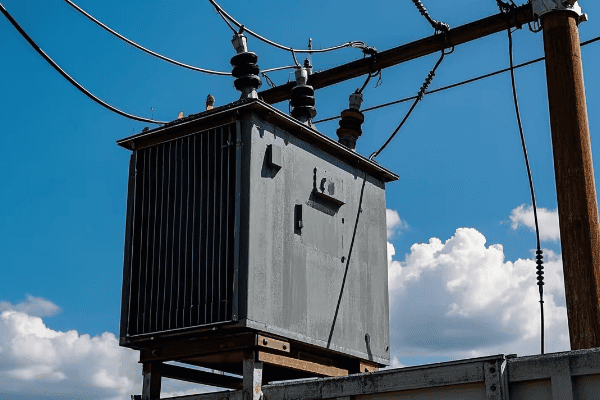
Let’s break down the factors that contribute to the cost-effectiveness of pad mount transformers:
1. Lower Maintenance Costs
Pad mount transformers typically require less maintenance:
- Easier Access: Ground-level installation reduces labor time and equipment needs for routine checks.
- Protected Components: Enclosed design means less wear from environmental factors.
- Fewer Emergency Repairs: Better weather resistance leads to fewer failure-related maintenance calls.
2. Longer Lifespan
The design of pad mount transformers often results in a longer operational life:
- Better Protection: Shielding from elements extends component life.
- Easier Upgrades: Modular designs allow for component upgrades without full replacement.
- Reduced Stress: Less exposure to extreme temperatures and weather events.
3. Energy Efficiency
Many pad mount transformers are designed for improved energy efficiency:
- Advanced Materials: Use of low-loss core materials reduces ongoing energy waste.
- Optimized Cooling: Better cooling systems maintain efficiency over time.
- Smart Features: Compatibility with smart grid technologies for optimized load management.
4. Reduced Land Costs
In urban areas, pad mount transformers can lead to land cost savings:
- Smaller Footprint: Requires less dedicated land than pole-mounted systems.
- Multi-Use Spaces: Area around pad mount transformers can often serve other purposes.
- Underground Integration: Allows for more efficient use of valuable urban real estate.
5. Lower Insurance and Liability Costs
The safer design of pad mount transformers can lead to cost savings in unexpected areas:
- Reduced Accident Risk: Lower chance of public interaction means fewer liability issues.
- Better Safety Record: Can lead to lower insurance premiums for utility companies.
- Compliance with Regulations: Easier to meet evolving safety standards, avoiding potential fines.
Here’s a comparison of long-term cost factors between pad mount and pole mount transformers:
| Cost Factor | Pad Mount | Pole Mount |
|---|---|---|
| Initial Installation Cost | Higher | Lower |
| Annual Maintenance Cost | Lower | Higher |
| Expected Lifespan | 30-40 years | 20-30 years |
| Energy Efficiency | Generally Higher | Variable |
| Land Use Cost | Lower in urban areas | Higher in urban areas |
| Replacement Frequency | Less frequent | More frequent |
| Emergency Repair Costs | Lower | Higher |
| Insurance/Liability Costs | Potentially Lower | Potentially Higher |
I remember a project for a large urban development where we initially balked at the higher upfront costs of pad mount transformers. However, after conducting a 20-year total cost of ownership analysis, we found that the pad mount option would save nearly 30% in overall costs compared to pole-mounted units. This was due to lower maintenance needs, reduced energy losses, and the ability to use the land around the transformers for other purposes.
The cost-effectiveness of pad mount transformers extends beyond direct financial savings:
- Improved Reliability: Fewer outages mean less lost revenue for businesses and fewer inconveniences for residents.
- Aesthetic Value: In residential and commercial areas, the improved aesthetics can contribute to higher property values.
- Futureproofing: Easier integration with smart grid technologies can reduce future upgrade costs.
For utility companies and city planners, the long-term savings of pad mount transformers translate to:
- Better Budget Allocation: More predictable maintenance costs allow for better long-term financial planning.
- Improved Customer Satisfaction: Reliable service and lower long-term costs can be passed on to consumers.
- Sustainable Investment: Aligns with long-term sustainability goals, potentially attracting environmentally conscious investors.
In the broader context of infrastructure development, the cost-effectiveness of pad mount transformers contributes to:
- More Efficient Urban Planning: Allows for better use of limited urban space.
- Reduced Environmental Costs: Lower energy losses and longer lifespan mean reduced environmental impact over time.
- Innovation Incentives: The success of pad mount transformers encourages further investment in efficient electrical technologies.
In conclusion, while the initial investment in pad mount transformers may be higher, their long-term cost-effectiveness makes them a smart choice for modern electrical infrastructure. By considering the total cost of ownership, including maintenance, energy efficiency, and lifespan, it becomes clear that pad mount transformers offer significant financial benefits over their operational life.
Conclusion
Pad mount transformers offer numerous advantages in modern electrical systems, including enhanced safety, space efficiency, aesthetic appeal, improved reliability, easy maintenance, environmental protection, and long-term cost-effectiveness. These benefits make them an ideal choice for urban and suburban power distribution needs, balancing functionality with community and environmental considerations.
