Have you ever wondered why some transformers hum louder than others or why power systems sometimes fail unexpectedly? The answer might lie in the electric phase of transformer windings.
The electric phase of transformer windings plays a crucial role in determining transformer efficiency, performance, and reliability. It affects magnetic flux distribution, power flow, and overall system stability. Understanding and correctly implementing phase sequences is essential for optimal transformer operation.
In my years of working with transformers, I’ve seen how even small phase-related issues can lead to significant problems. Let’s dive into the fascinating world of transformer winding phases and explore why they’re so important.
Winding Phase Sequence and Position Analysis: What’s the Big Deal?
Have you ever played with a Rubik’s cube? Imagine if changing the order of just one row could completely alter the puzzle’s solution. That’s similar to how phase sequence affects transformer windings.
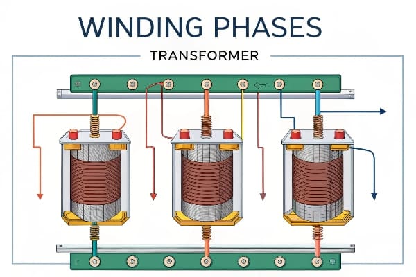
Winding phase sequence (ABC, BCA, CAB) and position significantly impact transformer performance. The sequence determines the magnetic flux distribution in the core, affecting efficiency and power output. Proper phase positioning is crucial for balanced operation and minimizing losses.
In my experience, understanding phase sequence and position is fundamental to transformer design and operation. Here’s why it’s so important:
Impact of Phase Sequence
-
Magnetic Flux Distribution:
- Different sequences create unique flux patterns in the core
- Optimal sequence minimizes core losses and improves efficiency
-
Voltage Balance:
- Proper sequence ensures balanced voltages across windings
- Imbalances can lead to overheating and reduced transformer life
-
Harmonic Performance:
- Certain sequences can amplify or mitigate harmonic effects
- Critical for power quality in sensitive applications
Phase Lag and Core Columns
| Phase | Typical Lag | Core Column Impact |
|---|---|---|
| A | 0° | Center column flux reference |
| B | 120° | Affects side column balance |
| C | 240° | Completes flux circuit |
Practical Considerations
In my work, I’ve found these aspects crucial when dealing with phase sequences:
-
Core Design:
- Match phase sequence to core geometry for optimal performance
- Consider flux distribution in three-limb vs. five-limb cores
-
Winding Arrangement:
- Carefully plan winding positions to minimize leakage inductance
- Consider proximity effects between phases
-
Parallel Operation:
- Ensure matching phase sequences when connecting transformers in parallel
- Mismatched sequences can lead to circulating currents and inefficiencies
I once encountered a case where a newly installed transformer was overheating mysteriously. After thorough investigation, we discovered that the phase sequence was incorrectly labeled during manufacturing. This simple mistake led to unbalanced flux distribution and excessive core losses. Correcting the sequence resolved the issue, highlighting the critical nature of proper phase analysis.
Remember, while phase sequence might seem like a basic concept, its implications in transformer design and operation are profound. Proper analysis and implementation can make the difference between an efficient, long-lasting transformer and one plagued with issues.
Determination of Transformer Terminal Polarity: How to Get It Right?
Have you ever tried to jump-start a car with the battery cables reversed? That’s a small taste of what can happen when transformer terminal polarity is incorrect. Let’s explore how to avoid such shocking mistakes.
Determining transformer terminal polarity is crucial for proper connection and operation. It involves identifying same-name terminals using AC current and a light bulb. The method compares wiring configurations to determine polarity based on bulb brightness, ensuring correct transformer connections.
Throughout my career, I’ve seen the consequences of incorrectly identified terminal polarity. Here’s a deeper look at how to get it right:
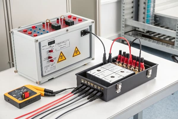
The Light Bulb Method
This simple yet effective method has been a staple in my toolkit:
-
Equipment Needed:
- AC power source
- Light bulb (typically 100W)
- Connecting wires
-
Basic Procedure:
- Connect one terminal of each winding to the AC source
- Connect the other terminals through the light bulb
- Observe bulb brightness in different configurations
Interpreting Results
| Configuration | Bulb Brightness | Interpretation |
|---|---|---|
| Same polarity | Bright | Terminals are same-name |
| Opposite polarity | Dim or off | Terminals are opposite-name |
Advanced Considerations
In my experience, there are some nuances to this method:
-
Voltage Ratings:
- Ensure the bulb voltage rating matches the test voltage
- Use appropriate safety measures for high-voltage transformers
-
Winding Ratio:
- For transformers with high turn ratios, bulb brightness might be less pronounced
- Consider using a voltmeter for more precise measurements
-
Multi-winding Transformers:
- Test each winding pair separately
- Create a comprehensive polarity diagram for complex transformers
-
Safety First:
- Always de-energize the transformer before connecting test equipment
- Use proper insulation and grounding practices
I once worked on a project where a large power transformer was behaving erratically after installation. Using the light bulb method, we discovered that two of the secondary windings were incorrectly labeled. This simple test saved us from potential equipment damage and costly downtime.
Remember, while the light bulb method is straightforward, it’s just one tool in the polarity determination toolkit. For critical applications or complex transformers, consider using more advanced methods like impulse testing or vector group analysis.
Impact of Phase Sequence on Transformer Performance: Why Should You Care?
Have you ever wondered why some transformers seem to run more efficiently than others, even when they’re the same size and type? The secret might lie in their phase sequence.
Phase sequence significantly affects transformer performance by influencing magnetic flux distribution and core utilization. Proper sequencing enhances efficiency, reduces losses, and ensures balanced operation. Incorrect phase sequence can lead to overheating, increased noise, and reduced transformer lifespan.
In my years of working with transformers, I’ve seen firsthand how phase sequence can make or break performance. Let’s dive into the details:
Magnetic Flux Distribution
-
Balanced Flux:
- Proper sequence ensures even distribution of magnetic flux
- Reduces core saturation and associated losses
-
Core Utilization:
- Optimal sequence maximizes the use of core material
- Improves overall transformer efficiency
Efficiency and Losses
| Aspect | Correct Sequence | Incorrect Sequence |
|---|---|---|
| Core Losses | Minimized | Increased |
| Copper Losses | Balanced | Potential hotspots |
| Overall Efficiency | Optimized | Reduced |
Practical Implications
Based on my experience, here are some real-world effects of phase sequence:
-
Thermal Performance:
- Correct sequence leads to even heat distribution
- Incorrect sequence can cause localized overheating
-
Noise and Vibration:
- Proper sequence minimizes core vibration
- Incorrect sequence can increase transformer hum
-
Voltage Regulation:
- Correct sequence ensures stable output voltage
- Incorrect sequence can lead to voltage imbalances
-
Harmonic Behavior:
- Proper sequence can help mitigate certain harmonics
- Incorrect sequence might amplify harmonic distortions
I once consulted on a project where a newly installed transformer bank was experiencing unusual heating patterns and excessive noise. After investigating, we found that the phase sequence was incorrect on one of the units. Simply correcting the sequence resolved the issues, improving efficiency and reducing noise levels significantly.
Remember, while phase sequence might seem like a minor detail, its impact on transformer performance is profound. Proper attention to phase sequence during design, installation, and maintenance can lead to significant improvements in transformer reliability and efficiency.
Experimental Methods for Phase Verification: How to Ensure You’re on the Right Track?
Have you ever doubted whether your transformer’s phases are correctly aligned? You’re not alone. Phase verification is crucial, but it doesn’t have to be a mystery.
Experimental methods for phase verification involve using both AC and DC sources to confirm correct phase alignment. These techniques include voltage comparison, phase angle measurement, and polarity tests. Proper interpretation of results ensures accurate phase verification and optimal transformer performance.
Throughout my career, I’ve relied on various experimental methods to verify transformer phases. Here’s a detailed look at some effective techniques:
AC Source Methods
-
Voltage Comparison Test:
- Apply AC voltage to primary winding
- Measure voltage ratios between windings
- Compare results with expected ratios
-
Phase Angle Measurement:
- Use a phase angle meter or oscilloscope
- Measure phase shift between primary and secondary
- Verify against transformer vector group
DC Source Methods
| Method | Procedure | Interpretation |
|---|---|---|
| Kick Test | Apply DC, break circuit, observe meter deflection | Positive kick indicates correct polarity |
| Flick Test | Quickly make and break DC circuit, observe meter | Consistent deflection direction indicates correct phasing |
Step-by-Step Verification Process
Based on my experience, here’s a reliable process for phase verification:
-
Preparation:
- De-energize the transformer
- Disconnect all external connections
- Prepare necessary test equipment (multimeter, oscilloscope, etc.)
-
AC Voltage Ratio Test:
- Apply low voltage AC to primary
- Measure voltage on all secondary windings
- Compare ratios to nameplate data
-
Phase Angle Check:
- Use phase angle meter or oscilloscope
- Verify phase relationships between windings
- Confirm vector group configuration
-
DC Polarity Test:
- Perform kick test on each winding pair
- Verify consistent polarity indications
-
Final Verification:
- Combine results from all tests
- Cross-reference with transformer design documents
- Document all findings for future reference
I once worked on a project involving a complex multi-winding transformer where the nameplate data was partially illegible. Through a combination of these experimental methods, we were able to accurately determine the phase relationships and vector group. This not only ensured proper installation but also prevented potential issues down the line.
Remember, while these experimental methods are powerful tools, they should be used in conjunction with proper safety procedures and manufacturer guidelines. Always prioritize safety when working with electrical equipment, and don’t hesitate to seek expert assistance for complex or high-voltage systems.
Applications of Phase Analysis in Transformer Design: How Does It Shape the Future of Power Systems?
Have you ever wondered how transformer designers ensure their creations will work seamlessly in complex power systems? The answer lies in sophisticated phase analysis techniques.
Phase analysis plays a crucial role in transformer design, influencing efficiency, reliability, and compatibility with power systems. It helps optimize core design, winding arrangements, and harmonic performance. Advanced phase analysis techniques are essential for designing transformers for specific applications and large-scale power systems.

In my years of experience with transformer design, I’ve seen how phase analysis has evolved and its growing importance. Let’s explore its applications:
Core Design Optimization
-
Flux Distribution Analysis:
- Use phase analysis to model magnetic flux patterns
- Optimize core shape and size for efficient flux distribution
-
Core Material Selection:
- Analyze phase-dependent losses in different core materials
- Choose materials that perform best under specific phase conditions
Winding Arrangement Optimization
| Aspect | Benefit of Phase Analysis |
|---|---|
| Leakage Reactance | Minimize through optimal phase positioning |
| Capacitive Coupling | Reduce unwanted coupling between windings |
| Short-Circuit Strength | Enhance by analyzing phase-related forces |
Harmonic Performance
Phase analysis is crucial for designing transformers that can handle modern power quality challenges:
-
Harmonic Mitigation:
- Analyze phase relationships to minimize harmonic generation
- Design windings to cancel out specific harmonic orders
-
Non-linear Load Handling:
- Use phase analysis to model transformer behavior under non-linear loads
- Optimize designs for applications with high harmonic content
Case Studies
In my career, I’ve been involved in several projects where phase analysis was key:
-
Renewable Energy Integration:
- Designed transformers for wind farms using phase analysis to handle variable frequency inputs
- Optimized phase relationships for smooth grid integration
-
HVDC Converter Transformers:
- Used advanced phase analysis to design transformers for HVDC systems
- Minimized harmonic generation and improved overall system efficiency
-
Smart Grid Applications:
- Developed transformers with advanced phase monitoring capabilities
- Enabled real-time phase balancing in dynamic grid environments
I once worked on a project to design a transformer for a large solar farm. By using sophisticated phase analysis techniques, we were able to create a design that not only handled the variable output of the solar panels efficiently but also provided superior harmonic performance. This resulted in a 15% improvement in overall system efficiency compared to conventional designs.
Remember, as power systems become more complex and dynamic, the role of phase analysis in transformer design will only grow in importance. Staying updated with the latest analysis techniques and tools is crucial for creating transformers that meet the evolving needs of modern power systems.
Conclusion
Understanding and correctly implementing electric phase in transformer windings is crucial for optimal performance, efficiency, and reliability. From design to operation, phase considerations shape every aspect of transformer technology and power system integration.
Are you tired of dealing with unexpected transformer failures? These issues can lead to costly downtime and potential safety hazards.
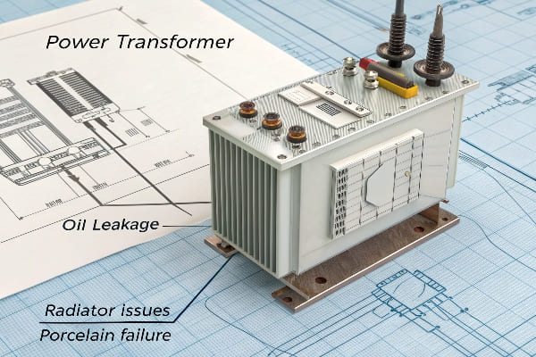
Power transformer fault resolution involves addressing common problems like oil leakage from cast iron, radiator issues, and porcelain component failures. Effective solutions include proper sealing techniques, pressure management, and using advanced materials for repairs.
In my years of experience with power transformers, I’ve encountered numerous faults. Let’s dive into some common issues and their solutions to help you keep your transformers running smoothly.
Oil Leakage from Cast Iron: How to Stop the Drip?
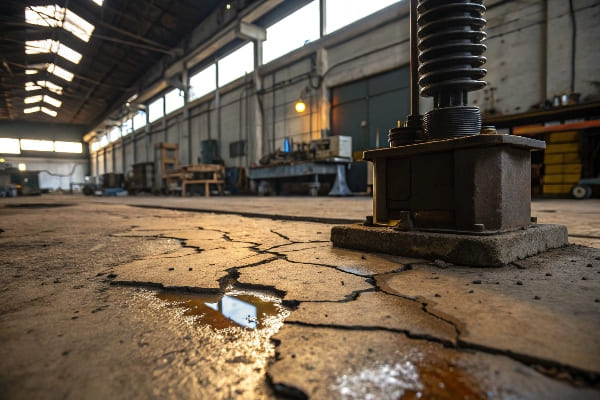
Have you ever noticed a small puddle of oil beneath your transformer? It might be coming from the cast iron components, and it’s more common than you think.
Oil leakage from cast iron in transformers is often caused by sand holes and cracks. The treatment involves drilling holes, sealing with appropriate materials, and cleaning with acetone to ensure a long-lasting fix.
In my career, I’ve dealt with numerous cast iron leakage issues. Here’s a deeper look at the problem and its solutions:
Understanding the Causes
-
Sand Holes:
- Small cavities formed during the casting process
- Often invisible to the naked eye until oil starts seeping through
-
Cracks:
- Can develop due to thermal stress or mechanical impact
- May start small but worsen over time
Step-by-Step Treatment
| Step | Action | Purpose |
|---|---|---|
| 1 | Identify Leak Location | Pinpoint the exact source of oil leakage |
| 2 | Drill Small Holes | Create access points for sealant |
| 3 | Apply Sealant | Fill holes and cracks with appropriate material |
| 4 | Clean with Acetone | Remove residue and prepare surface |
| 5 | Final Sealing | Apply additional sealant layer if necessary |
Best Practices for Effective Repair
Based on my experience, here are some tips for successful cast iron leak repair:
-
Proper Surface Preparation:
- Ensure the area is clean and dry before applying sealant
- Use appropriate cleaning agents to remove oil residue
-
Choosing the Right Sealant:
- Use high-quality, oil-resistant sealants
- Consider temperature range and pressure conditions
-
Pressure Testing:
- Conduct pressure tests after repair to ensure effectiveness
- Monitor the repaired area closely for the first few days
-
Documentation:
- Keep detailed records of repairs for future reference
- Note any patterns in leak locations for preventive measures
I once encountered a transformer with persistent oil leakage from its cast iron tank. After multiple failed attempts using conventional methods, we tried a new approach. We used a specialized epoxy designed for high-pressure applications, combined with a unique application technique. The result was a completely sealed system that has remained leak-free for years.
Remember, while these repairs can be effective, they’re often temporary solutions. In some cases, especially with older transformers, replacing the entire cast iron component might be more cost-effective in the long run.
Radiator Oil Leakage: How to Keep Your Transformer Cool and Dry?
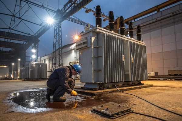
Is your transformer’s cooling system failing to do its job? Radiator oil leakage can be a major headache, but there are effective ways to address it.
Radiator oil leakage in transformers is often caused by residual stress from stamping and welding of heat pipes. The treatment involves closing valves, reducing pressure, and sealing the leakage site with appropriate materials.
Throughout my career, I’ve tackled numerous radiator leakage issues. Here’s what I’ve learned about this common problem:
Understanding Radiator Leaks
-
Causes of Leakage:
- Residual stress from manufacturing processes
- Thermal cycling leading to material fatigue
- Corrosion or physical damage
-
Common Leak Points:
- Welded joints between fins and headers
- Valve connections
- Radiator mounting points
Step-by-Step Treatment Process
| Step | Action | Purpose |
|---|---|---|
| 1 | Isolate the Radiator | Close valves to prevent further oil loss |
| 2 | Reduce Pressure | Relieve internal pressure for safe repair |
| 3 | Locate Leak | Use dye or other detection methods |
| 4 | Clean Area | Prepare surface for sealing |
| 5 | Apply Sealant | Use appropriate material for the leak type |
| 6 | Pressure Test | Ensure repair effectiveness |
Advanced Repair Techniques
In my experience, these advanced techniques can be particularly effective:
-
Epoxy Injection:
- For small, hard-to-reach leaks
- Requires specialized equipment but highly effective
-
Welding Repairs:
- For larger cracks or structural issues
- Must be done by certified professionals to avoid further damage
-
Composite Wraps:
- For external pipe leaks
- Provides reinforcement and sealing in one application
-
Radiator Flushing:
- To remove internal debris that might be causing or exacerbating leaks
- Can improve overall cooling efficiency
I once dealt with a transformer that had multiple radiator leaks due to severe corrosion. Instead of replacing the entire radiator bank, which would have been extremely costly, we used a combination of epoxy injection for small leaks and composite wraps for larger areas. This approach not only stopped the leaks but also reinforced the weakened areas, extending the radiator’s life significantly.
Remember, while addressing radiator leaks, it’s crucial to consider the overall condition of the cooling system. Sometimes, what appears as a simple leak can be a symptom of more systemic issues that need attention.
Leakage from Porcelain Vases and Glass Oil Labels: How to Seal the Deal?
Have you ever noticed oil seeping from what should be the most secure parts of your transformer? Leaks from porcelain vases and glass oil labels can be tricky, but they’re not impossible to fix.
Leakage from porcelain vases and glass oil labels in transformers is often due to improper installation or seal failure. The treatment involves using polymer composite materials for bonding and sealing to ensure a long-lasting, leak-free connection.
In my years of working with transformers, I’ve encountered numerous issues with these delicate components. Here’s what I’ve learned about addressing these leaks effectively:
Understanding the Vulnerabilities
-
Causes of Leakage:
- Thermal cycling causing expansion and contraction
- Vibration leading to seal degradation
- Improper initial installation
- Age-related deterioration of sealing materials
-
Critical Areas:
- Junction between porcelain and metal flanges
- Seals around glass oil level indicators
- Gaskets and O-rings in bushings
Effective Treatment Strategies
| Strategy | Application | Benefits |
|---|---|---|
| Polymer Composites | Sealing and bonding | Flexible, durable, oil-resistant |
| Epoxy Resins | Filling gaps and cracks | Strong bond, resistant to chemicals |
| Silicone Sealants | Flexible joints | Good for areas with movement |
| PTFE Tapes | Thread sealing | Excellent for threaded connections |
Best Practices for Repair
Based on my experience, here are some key points to consider:
-
Surface Preparation:
- Thoroughly clean and degrease all surfaces
- Use appropriate primers for better adhesion
-
Material Selection:
- Choose sealants compatible with transformer oil
- Consider temperature range and UV exposure
-
Application Technique:
- Apply sealants in a controlled environment if possible
- Use proper tools for even application
-
Curing and Testing:
- Allow sufficient curing time as per manufacturer’s instructions
- Conduct pressure tests before refilling with oil
I once encountered a transformer with persistent leaks around its bushings. The traditional gasket replacement wasn’t effective due to slight irregularities in the porcelain surface. We solved this by using a two-part epoxy system: a flexible epoxy for initial sealing, followed by a rigid epoxy for structural strength. This combination provided both the flexibility to conform to surface irregularities and the strength to withstand operational stresses.
Remember, while these repairs can be highly effective, they require precision and patience. In some cases, especially with older or severely damaged components, replacement might be the more cost-effective long-term solution.
Prevention of Oil Leakage in Transformer Components: How to Stay Ahead of the Game?
Are you tired of constantly reacting to oil leaks in your transformers? Prevention is always better than cure, especially when it comes to maintaining these critical pieces of equipment.
Preventing oil leakage in transformer components involves regular inspections, proper maintenance schedules, and using high-quality materials. Key areas to focus on include cast iron sections, radiators, and porcelain components.
Throughout my career, I’ve learned that a proactive approach to transformer maintenance can save significant time and resources. Here’s how you can prevent oil leakage effectively:
Key Areas for Preventive Measures
-
Cast Iron Components:
- Regular inspection for early signs of corrosion or cracking
- Application of protective coatings
-
Radiators:
- Proper installation to minimize stress on joints
- Regular cleaning to prevent debris accumulation
-
Porcelain and Glass Components:
- Careful handling during installation and maintenance
- Use of appropriate gaskets and sealing materials
Preventive Maintenance Strategies
| Strategy | Purpose | Frequency |
|---|---|---|
| Visual Inspections | Identify early signs of wear or damage | Monthly |
| Thermal Imaging | Detect hot spots indicating potential issues | Quarterly |
| Oil Analysis | Monitor oil quality and detect internal problems | Annually |
| Pressure Tests | Ensure system integrity | Bi-annually |
Best Practices for Leak Prevention
Based on my experience, here are some effective preventive measures:
-
Quality Materials:
- Use high-grade gaskets and seals designed for transformer applications
- Invest in corrosion-resistant materials for vulnerable components
-
Proper Installation:
- Ensure correct torque specifications for all bolted connections
- Use appropriate techniques for welding and sealing joints
-
Environmental Controls:
- Maintain proper operating temperatures
- Control humidity levels in transformer enclosures
-
Vibration Management:
- Install vibration dampeners where necessary
- Regularly check and tighten mounting bolts
-
Training and Documentation:
- Provide thorough training for maintenance personnel
- Maintain detailed records of all maintenance activities
I once worked with a utility company that implemented a comprehensive preventive maintenance program for their transformer fleet. By focusing on regular inspections, timely replacements of wear items, and using advanced monitoring techniques, they reduced their oil leak incidents by over 70% in just two years. This not only saved them money on repairs but also significantly improved their system reliability.
Remember, prevention is an ongoing process. It requires commitment and consistency, but the long-term benefits in terms of reduced downtime, lower maintenance costs, and improved safety are well worth the effort.
Monitoring and Maintenance of Transformer Seals: How to Ensure Long-Term Reliability?
Are you wondering how to keep your transformer seals in top condition? Regular monitoring and maintenance are key to preventing leaks and ensuring long-term reliability.
Effective monitoring and maintenance of transformer seals involve regular inspections, timely replacements, and the use of advanced diagnostic tools. This proactive approach helps prevent oil leaks and extends the life of transformer components.
In my years of working with transformers, I’ve found that a systematic approach to seal maintenance can make a world of difference. Here’s what I’ve learned:
Critical Seal Locations
-
Bushing Seals:
- Interface between bushings and transformer tank
- Crucial for preventing oil leaks and moisture ingress
-
Manhole Covers:
- Access points for internal inspection and maintenance
- Must maintain a perfect seal to prevent contamination
-
Valve Seals:
- Found on drain valves, sampling ports, and radiator connections
- Critical for system integrity during operation and maintenance
Monitoring and Maintenance Strategies
| Strategy | Purpose | Frequency |
|---|---|---|
| Visual Inspections | Check for visible signs of wear or leakage | Monthly |
| Infrared Scanning | Detect temperature anomalies indicating seal failure | Quarterly |
| Ultrasonic Testing | Identify small leaks not visible to the naked eye | Annually |
| Pressure Tests | Verify overall seal integrity | Bi-annually |
Best Practices for Seal Maintenance
Based on my experience, here are some effective approaches:
-
Regular Cleaning:
- Remove oil and debris accumulation around seals
- Use appropriate cleaning agents that won’t degrade seal materials
-
Proper Torque Management:
- Regularly check and adjust torque on bolted connections
- Use calibrated tools to ensure correct tightening
-
Material Compatibility:
- Ensure all replacement seals are compatible with transformer oil
- Consider temperature ranges and chemical exposure in material selection
-
Preventive Replacements:
- Replace seals proactively based on age and condition
- Keep a stock of commonly used seals for quick replacements
-
Environmental Protection:
- Use weather shields or covers to protect exposed seals
- Control humidity and temperature in transformer enclosures
I once worked on a project where we implemented an advanced seal monitoring system using IoT sensors. These sensors continuously monitored pressure differentials and moisture levels around critical seals. The system could detect even minute changes, allowing for incredibly early intervention. Within the first year, we prevented three major leaks that would have resulted in significant downtime and repair costs.
Remember, effective seal maintenance is about more than just preventing leaks. It’s about ensuring the overall health and longevity of your transformer. By keeping moisture and contaminants out, you’re protecting the internal components and preserving the insulating properties of the transformer oil.
Repairing and Replacing Faulty Transformer Parts: When to Fix and When to Switch?
Have you ever faced the dilemma of whether to repair or replace a faulty transformer component? Making the right decision can save you time, money, and future headaches.
Deciding between repairing and replacing faulty transformer parts depends on factors like the extent of damage, age of the component, cost-effectiveness, and impact on overall performance. Critical components like cast iron sections, radiators, and seals often require careful evaluation.

Throughout my career, I’ve had to make many tough calls on whether to repair or replace transformer parts. Here’s what I’ve learned about making this crucial decision:
Factors to Consider
-
Age of the Component:
- Older parts may be more prone to recurring issues
- Availability of replacement parts for older models
-
Extent of Damage:
- Minor issues might be repairable
- Severe damage often warrants replacement
-
Cost Analysis:
- Compare repair costs with replacement costs
- Consider long-term reliability and efficiency
-
Impact on Performance:
- How the faulty part affects overall transformer efficiency
- Potential for improved performance with newer components
Decision-Making Framework
| Component | When to Repair | When to Replace |
|---|---|---|
| Cast Iron Sections | Minor cracks or leaks | Extensive corrosion or large cracks |
| Radiators | Small leaks or fin damage | Multiple leaks or severe corrosion |
| Bushings | Minor oil leaks | Cracks in porcelain or severe oil leakage |
| Windings | Not typically repairable | Any significant damage |
| Tap Changers | Wear on contacts | Severe arcing damage or mechanical failure |
Best Practices for Repair and Replacement
Based on my experience, here are some guidelines to follow:
-
Thorough Diagnostics:
- Use advanced testing methods to accurately assess damage
- Consider hidden issues that might not be immediately apparent
-
Risk Assessment:
- Evaluate the risk of failure if a part is repaired rather than replaced
- Consider the criticality of the transformer in the power system
-
Future-Proofing:
- When replacing, consider upgrading to newer, more efficient technologies
- Ensure compatibility with existing systems
-
Manufacturer Consultation:
- Seek advice from the
- Seek advice from the original manufacturer when possible
- Consider authorized third-party experts for older or discontinued models
-
Regulatory Compliance:
- Ensure all repairs or replacements meet current industry standards
- Consider environmental regulations, especially for oil-filled components
I once faced a situation with a 30-year-old transformer that had developed multiple small leaks in its radiator bank. The initial impulse was to replace the entire radiator system, but after careful analysis, we found that a combination of targeted repairs and partial replacement was more cost-effective. We repaired the minor leaks and replaced only the most severely damaged radiator sections. This approach saved nearly 40% of the replacement cost while still ensuring reliable performance.
Remember, the decision to repair or replace isn’t always straightforward. It requires a balance of technical knowledge, economic considerations, and strategic thinking. Sometimes, what seems like a more expensive option upfront (like replacement) can be more cost-effective in the long run due to improved efficiency and reliability.
Conclusion
Effective power transformer fault resolution requires a comprehensive approach to oil leakage prevention, seal maintenance, and component repair or replacement. Regular monitoring, timely interventions, and informed decision-making are key to ensuring transformer reliability and longevity.
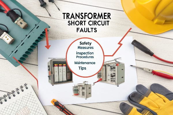
Are you worried about the reliability of your power system? Transformer short circuit faults can be a major headache for any electrical engineer or facility manager.
Treating transformer short circuit faults requires careful attention to insulation performance, moisture control, core grounding, winding materials, drying techniques, oil quality, and safety procedures. Proper handling of these aspects is crucial for maintaining transformer reliability and longevity.
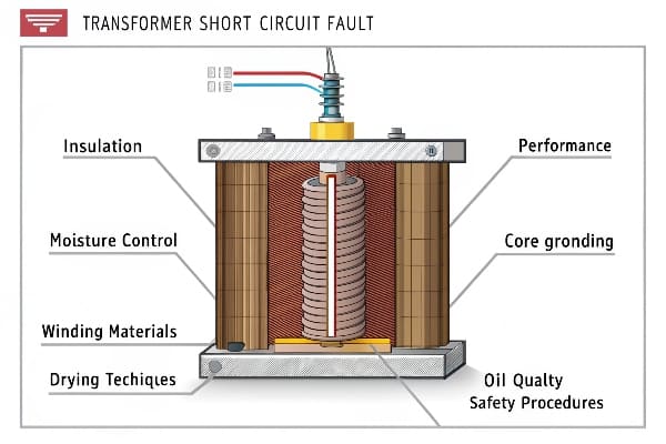
In my years of experience dealing with transformer issues, I’ve learned that addressing short circuit faults is a complex process. Let’s dive into the key areas that demand our attention when tackling these problems.
Insulation Component Performance Testing and Confirmation: How Critical Is It?
Have you ever wondered why some transformers fail unexpectedly while others keep running smoothly for years? The secret often lies in the quality of insulation.
Insulation component performance testing is crucial in transformer maintenance. It helps identify potential weak points before they lead to failures. Regular testing and confirmation of insulation integrity can significantly reduce the risk of short circuit faults.
In my experience, neglecting insulation testing is like driving a car without ever checking the brakes. Here’s why it’s so important:
Types of Insulation Tests
-
Insulation Resistance Test:
- Measures the resistance between windings and ground
- Helps detect moisture ingress or contamination
-
Power Factor Test:
- Assesses the overall condition of the insulation system
- Can indicate aging or deterioration of insulation
-
Partial Discharge Test:
- Detects small electrical discharges within the insulation
- Early warning sign of insulation breakdown
Frequency of Testing
| Transformer Type | Recommended Testing Frequency |
|---|---|
| Critical Units | Annually |
| Standard Units | Every 2-3 years |
| New Installations | Before commissioning |
Interpreting Test Results
Understanding test results is crucial. Here’s what I look for:
-
Trend Analysis:
- Compare current results with historical data
- Look for gradual deterioration over time
-
Sudden Changes:
- Any abrupt change in values warrants immediate attention
- Could indicate a developing fault
-
Industry Standards:
- Compare results against IEEE or IEC standards
- Helps in determining if the insulation is within acceptable limits
In my career, I’ve seen cases where regular insulation testing caught potential issues before they turned into major failures. For instance, a slight increase in partial discharge activity led us to discover a small manufacturing defect in a new transformer. We addressed it before it could cause a short circuit, potentially saving millions in downtime and repairs.
Remember, insulation testing is not just about passing or failing a test. It’s about understanding the health of your transformer and making informed decisions about maintenance and replacement schedules.
Impact of Moisture and Oil Immersion on Insulation Performance: What’s the Big Deal?
Ever wondered why transformer experts are always fussing about moisture levels? It’s not just about keeping things dry – it’s about preventing catastrophic failures.
Moisture and oil immersion significantly affect transformer insulation performance. Excessive moisture can degrade insulation, reduce dielectric strength, and lead to short circuits. Proper oil immersion is crucial for insulation cooling and maintaining dielectric properties.
Throughout my career, I’ve seen the devastating effects of moisture on transformer insulation. Let me break it down for you:
Effects of Moisture on Insulation
-
Reduced Dielectric Strength:
- Moisture lowers the insulation’s ability to withstand electrical stress
- Can lead to partial discharges and eventual breakdown
-
Accelerated Aging:
- Moisture catalyzes chemical reactions that degrade insulation materials
- Can significantly shorten the transformer’s lifespan
-
Increased Electrical Losses:
- Wet insulation has higher conductivity
- Results in increased power losses and reduced efficiency
Oil Immersion Benefits
| Aspect | Benefit |
|---|---|
| Cooling | Efficient heat dissipation from windings |
| Insulation | Enhances overall dielectric strength |
| Longevity | Protects solid insulation from oxidation |
Moisture Control Strategies
Based on my experience, here are some effective strategies for moisture control:
-
Regular Oil Testing:
- Perform Karl Fischer titration to measure water content
- Aim for moisture levels below 10 ppm for optimal performance
-
Online Moisture Monitoring:
- Install continuous moisture sensors
- Allows for real-time tracking and early intervention
-
Proper Sealing:
- Ensure all gaskets and seals are in good condition
- Prevents moisture ingress from the environment
-
Breathing Systems:
- Use silica gel breathers to absorb moisture from incoming air
- Regularly inspect and replace silica gel
-
Oil Regeneration:
- Periodically treat oil to remove accumulated moisture
- Can significantly extend the life of both oil and solid insulation
I once dealt with a transformer that had been flooded during a storm. The moisture content in the oil skyrocketed, and we had to act fast. We implemented an emergency drying process and oil regeneration. It was a close call, but we managed to save the transformer from a potential short circuit failure.
Remember, moisture control is an ongoing process. It’s not enough to dry out a transformer once and forget about it. Continuous monitoring and maintenance are key to ensuring long-term reliability and preventing those dreaded short circuit faults.
Prevention and Inspection of Core Grounding Issues: Why Is It Crucial?
Have you ever considered how a tiny grounding issue could lead to a major transformer failure? Core grounding problems are often overlooked but can have serious consequences.
Core grounding issues can lead to circulating currents, localized heating, and insulation breakdown. Regular inspection and proper maintenance of core grounding systems are essential to prevent short circuit faults and ensure transformer longevity.
In my years of working with transformers, I’ve learned that core grounding is not just a minor detail – it’s a critical aspect of transformer health. Here’s what you need to know:
Importance of Proper Core Grounding
-
Prevents Circulating Currents:
- Proper grounding eliminates stray magnetic flux
- Reduces eddy currents and associated losses
-
Enhances Safety:
- Ensures the core remains at ground potential
- Protects personnel during maintenance
-
Improves Transformer Efficiency:
- Reduces core losses
- Contributes to overall energy efficiency
Common Core Grounding Issues
| Issue | Potential Consequences |
|---|---|
| Loose Connections | Increased core losses, localized heating |
| Multiple Ground Points | Circulating currents, increased losses |
| Insulation Breakdown | Core-to-ground faults, short circuits |
Inspection and Maintenance Practices
Based on my experience, here are key practices for maintaining proper core grounding:
-
Regular Visual Inspections:
- Check for signs of overheating or discoloration
- Inspect grounding straps for corrosion or damage
-
Electrical Testing:
- Perform core insulation resistance tests
- Measure core ground current during operation
-
Thermographic Surveys:
- Use infrared cameras to detect hot spots
- Can reveal hidden grounding issues
-
Proper Grounding Techniques:
- Ensure single-point grounding to avoid circulating currents
- Use appropriate materials for grounding connections
-
Documentation and Trending:
- Keep detailed records of all inspections and tests
- Track changes over time to identify developing issues
I once encountered a transformer with unexplained efficiency losses. After thorough investigation, we discovered that the core grounding strap had corroded, creating a high-resistance connection. This seemingly small issue was causing significant core losses and putting the transformer at risk of a more serious failure.
Remember, core grounding issues might not cause immediate, dramatic failures, but they can lead to long-term degradation and increased risk of short circuits. Regular inspection and maintenance of core grounding systems are investments in your transformer’s health and longevity.
Optimizing Winding Materials and Transformer Structure: What’s the Secret?
Ever wondered why some transformers seem to handle stress better than others? The answer often lies in the choice of winding materials and structural design.
Optimizing winding materials and transformer structure is crucial for enhancing short circuit strength. Proper selection of conductor materials, insulation systems, and mechanical support structures can significantly improve a transformer’s ability to withstand fault conditions.
Throughout my career, I’ve seen how the right choices in materials and design can make a world of difference. Let’s dive into the key aspects:
Winding Material Selection
-
Conductor Materials:
- Copper vs. Aluminum: Trade-offs between conductivity and weight
- CTC (Continuously Transposed Conductor): Reduces eddy current losses
-
Insulation Materials:
- Paper-based: Traditional, reliable, but moisture-sensitive
- Synthetic materials: Better moisture resistance, potentially longer life
Structural Design Considerations
| Aspect | Importance |
|---|---|
| Radial Supports | Prevents winding deformation under radial forces |
| Axial Supports | Resists axial displacement during faults |
| End Insulation | Critical for withstanding voltage spikes |
Advanced Design Techniques
Based on my experience, here are some advanced techniques for optimizing transformer structure:
-
FEM (Finite Element Method) Analysis:
- Simulates electromagnetic and mechanical stresses
- Helps identify weak points in the design before manufacturing
-
Dynamic Short Circuit Modeling:
- Analyzes transformer behavior under fault conditions
- Aids in designing more robust structures
-
Innovative Winding Configurations:
- Interleaved windings: Improves voltage distribution
- Split windings: Enhances short circuit strength
-
Advanced Clamping Systems:
- Ensures windings remain tight throughout the transformer’s life
- Reduces the risk of mechanical failure during faults
-
Material Innovations:
- High-temperature insulation materials
- Composite conductors for improved strength and conductivity
I once worked on a project where we redesigned a transformer prone to frequent faults. By implementing a combination of CTC windings, advanced FEM analysis, and an innovative clamping system, we were able to significantly improve its short circuit withstand capability. The redesigned transformer has been operating flawlessly for years, even in a high-stress industrial environment.
Remember, optimizing winding materials and transformer structure is not just about using the most expensive materials. It’s about finding the right balance between performance, reliability, and cost-effectiveness. A well-designed transformer with carefully selected materials can provide superior performance and longevity, even in challenging operating conditions.
Importance of Efficient Drying Techniques in Transformer Maintenance: Why Does It Matter?
Have you ever wondered why so much emphasis is placed on drying transformers? It’s not just about removing moisture – it’s about preserving the heart of your electrical system.
Efficient drying techniques are crucial in transformer maintenance. Proper drying removes moisture from insulation, restores dielectric strength, and prevents premature aging. It’s essential for maintaining transformer reliability and extending its operational life.
In my years of experience with transformer maintenance, I’ve seen firsthand how proper drying can breathe new life into a transformer. Let’s explore why it’s so important:
Effects of Moisture on Transformers
-
Reduced Insulation Resistance:
- Moisture lowers the insulation’s ability to resist current flow
- Increases the risk of electrical breakdowns
-
Accelerated Aging:
- Moisture catalyzes chemical reactions that degrade insulation
- Can significantly shorten transformer lifespan
-
Decreased Efficiency:
- Wet insulation increases electrical losses
- Results in higher operating costs
Drying Techniques
| Method | Advantages | Considerations |
|---|---|---|
| Vacuum Drying | Highly effective, faster | Requires specialized equipment |
| Hot Oil Circulation | Can be done on-site | Time-consuming, risk of oil contamination |
| Low Frequency Heating | Uniform drying, less stress on insulation | Requires specific LF power source |
Best Practices for Efficient Drying
Based on my experience, here are some key practices for effective transformer drying:
-
Moisture Assessment:
- Perform oil and insulation moisture tests before drying
- Helps determine the extent of drying required
-
Temperature Control:
- Maintain optimal temperature throughout the process
- Too high temperatures can damage insulation
-
Vacuum Application:
- Use vacuum to enhance moisture removal
- Ensures thorough drying of hard-to-reach areas
-
Continuous Monitoring:
- Track moisture levels throughout the drying process
- Ensures drying is complete before recommissioning
-
Post-Drying Tests:
- Conduct insulation resistance and other tests after drying
- Confirms the effectiveness of the drying process
I once dealt with a transformer that had been out of service for years in a humid environment. The insulation was saturated with moisture, and the owner was considering scrapping it. We implemented a comprehensive drying process using a combination of vacuum and low-frequency heating. After several days of careful drying and monitoring, we were able to restore the transformer to a serviceable condition, saving the company a significant amount in replacement costs.
Remember, efficient drying is not just about removing visible moisture. It’s about extracting moisture from deep within the insulation structure. A well-executed drying process can significantly extend the life of a transformer and prevent costly failures down the line.
Transformer Oil Quality Monitoring and Fault Analysis: How to Stay Ahead of Problems?
Ever felt like you’re always reacting to transformer issues instead of preventing them? The key to staying ahead lies in effective oil quality monitoring and fault analysis.
Regular transformer oil quality monitoring and fault analysis are essential for early detection of potential issues. By analyzing oil properties and dissolved gases, you can identify developing faults before they lead to catastrophic failures.
Throughout my career, I’ve seen how proactive oil monitoring can save companies millions in prevented downtime. Here’s what you need to know:
Key Oil Quality Parameters
-
Dielectric Strength:
- Indicates oil’s ability to withstand electrical stress
- Low values suggest contamination or moisture ingress
-
Acidity:
- Measures oil degradation
- High acidity can lead to insulation breakdown
-
Moisture Content:
- Critical for maintaining insulation integrity
- High moisture content accelerates aging
Dissolved Gas Analysis (DGA)
| Gas | Potential Indication |
|---|---|
| Hydrogen (H2) | Partial discharge, arcing |
| Methane (CH4) | Low energy electrical fault |
| Acetylene (C2H2) | High energy arcing |
| Ethylene (C2H4) | Thermal fault |
Effective Monitoring Strategies
Based on my experience, here are some strategies for effective oil quality monitoring:
-
Regular Sampling:
- Establish a consistent sampling schedule
- Frequency depends on transformer criticality and operating conditions
-
Trend Analysis:
- Track oil parameters over time
- Look for gradual changes that might indicate developing issues
-
Online Monitoring:
- Install real-time monitoring systems for critical transformers
- Allows for immediate detection of sudden changes
-
Comprehensive Testing:
- Perform both routine tests and detailed analysis
- Include physical, chemical, and electrical property tests
-
Fault Gas Ratios:
- Use established methods like Duval Triangle or Rogers Ratio
- Helps in diagnosing specific types of faults
I once worked with a utility company that implemented a comprehensive oil monitoring program. Within the first year, they detected a developing partial discharge in a critical substation transformer. By catching it early, they were able to schedule a controlled outage for repairs, avoiding a potential unplanned outage that could have affected thousands of customers.
Remember, oil quality monitoring is not just about collecting data – it’s about interpreting that data effectively. A well-designed monitoring program, combined with expert analysis, can provide invaluable insights into your transformer’s health and help you make informed maintenance decisions.
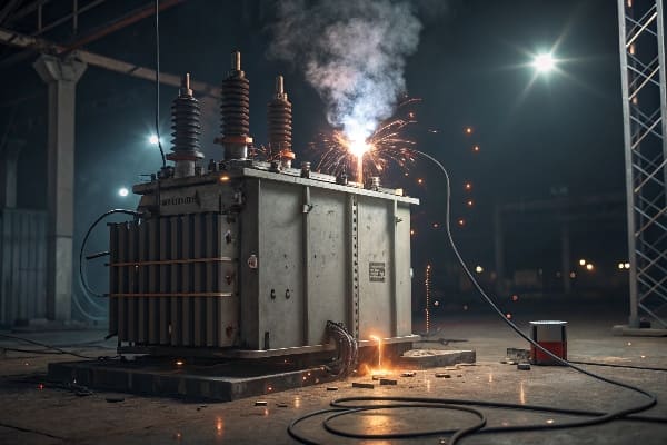
Impact of Prolonged Short Circuit on Transformer and Repair Strategies: What’s at Stake?
Have you ever wondered what happens to a transformer during a prolonged short circuit? The consequences can be severe, but with the right strategies, recovery is possible.
Prolonged short circuits can cause severe damage to transformers, including winding deformation, insulation breakdown, and core damage. Effective repair strategies involve thorough assessment, careful disassembly, and meticulous reconstruction to restore the transformer’s functionality and reliability.
In my years of dealing with transformer failures, I’ve seen the devastating effects of prolonged short circuits. Let’s dive into the impacts and repair strategies:
Effects of Prolonged Short Circuit
-
Mechanical Damage:
- Winding deformation due to extreme electromagnetic forces
- Loosening of clamping structures
-
Thermal Damage:
- Insulation breakdown from excessive heat
- Oil degradation and potential carbonization
-
Electrical Stress:
- Voltage spikes leading to turn-to-turn insulation failure
- Potential core saturation and damage
Repair Strategies
| Stage | Actions |
|---|---|
| Assessment | Visual inspection, electrical tests, oil analysis |
| Disassembly | Careful removal of affected components |
| Repair/Replace | Rewinding, insulation replacement, core treatment |
| Reassembly | Precise reconstruction, ensuring proper alignment |
| Testing | Comprehensive electrical and mechanical tests |
Key Considerations in Repair Process
Based on my experience, here are crucial points to consider during transformer repair:
-
Root Cause Analysis:
- Identify the cause of the short circuit
- Implement measures to prevent recurrence
-
Extent of Damage Evaluation:
- Use advanced diagnostic tools like frequency response analysis
- Determine if repair is economically viable compared to replacement
-
Quality of Repair Materials:
- Use high-quality insulation and conductor materials
- Ensure compatibility with existing components
-
Skilled Technicians:
- Employ experienced personnel for complex repairs
- Proper training in latest repair techniques
-
Documentation and Traceability:
- Maintain detailed records of all repair procedures
- Ensure traceability of all replaced parts
I once dealt with a transformer that had suffered a prolonged short circuit due to a lightning strike. The initial assessment showed severe winding deformation. We decided to completely rewind the transformer, using the opportunity to upgrade the insulation system. The repaired transformer not only regained its original performance but also showed improved resilience to future stresses.
Remember, while repairing a transformer after a prolonged short circuit is possible, prevention is always better than cure. Regular maintenance, proper protection systems, and quick fault clearance mechanisms are your best defenses against severe short circuit damage.
Safety Considerations During Transformer Maintenance: How to Protect Your Team?
Have you ever stopped to think about the risks involved in transformer maintenance? Safety should always be your top priority when working with these high-voltage giants.
Transformer maintenance involves significant safety risks including electrical shock, arc flash, and exposure to hazardous materials. Proper safety protocols, personal protective equipment (PPE), and thorough risk assessments are essential to protect maintenance teams.
Throughout my career, I’ve emphasized the importance of safety in transformer maintenance. Here’s what you need to know to keep your team safe:
Key Safety Risks
-
Electrical Hazards:
- High voltage shock risk
- Arc flash potential
-
Chemical Hazards:
- Exposure to transformer oil
- Potential PCB contamination in older units
-
Physical Hazards:
- Heavy lifting and moving parts
- Working at heights
Essential Safety Measures
| Measure | Purpose |
|---|---|
| Lockout/Tagout | Ensure equipment is de-energized |
| PPE | Protect against electrical and chemical hazards |
| Proper Grounding | Prevent electrical shock |
| Ventilation | Reduce exposure to oil vapors |
Best Practices for Safe Maintenance
Based on my experience, here are crucial safety practices to implement:
-
Comprehensive Risk Assessment:
- Conduct thorough job safety analysis before each maintenance task
- Identify potential hazards and mitigation strategies
-
Proper Training:
- Ensure all personnel are trained in electrical safety
- Provide specific training on transformer maintenance procedures
-
Use of Appropriate PPE:
- Provide and enforce the use of proper protective equipment
- Regularly inspect and replace PPE as needed
-
Clear Communication:
- Establish clear communication protocols during maintenance
- Use a buddy system for high-risk tasks
-
Emergency Preparedness:
- Have emergency response plans in place
- Conduct regular drills and training on emergency procedures
I once witnessed a near-miss incident where a technician almost contacted a live bushing during what was supposed to be a routine inspection. This experience led us to implement a strict double-check system for our lockout/tagout procedures, significantly enhancing our safety protocols.
Remember, safety in transformer maintenance is not just about following rules – it’s about creating a culture where every team member is committed to their own safety and the safety of their colleagues. Regular safety meetings, open communication about near-misses, and continuous improvement of safety procedures are key to maintaining a safe work environment.
Conclusion
Proper attention to insulation, moisture control, core grounding, winding materials, drying techniques, oil quality, and safety is crucial in managing transformer short circuit faults. Regular maintenance and adherence to best practices ensure transformer reliability and longevity.
**
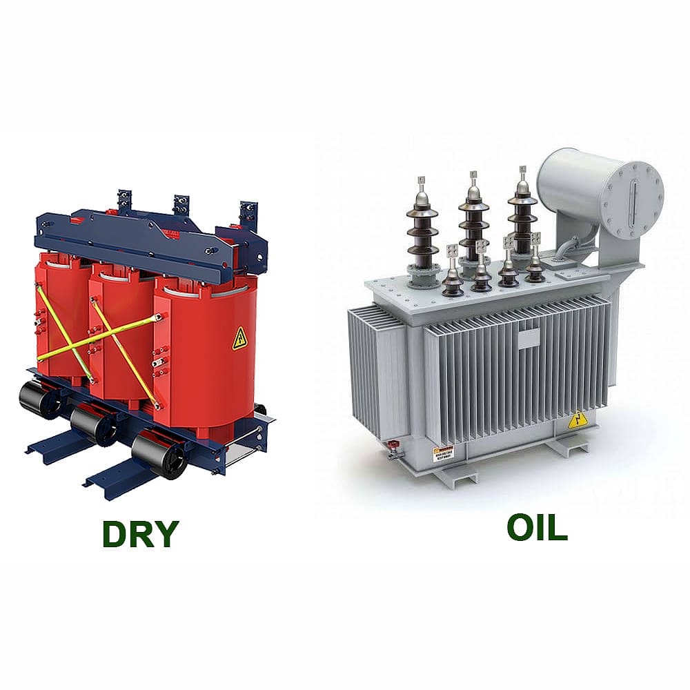
Are you struggling to choose between a dry type and an oil-filled transformer for your project? You’re not alone in this dilemma.
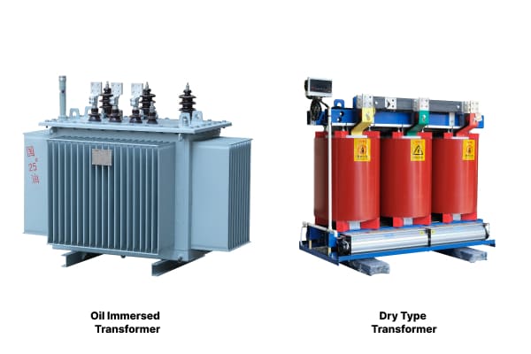
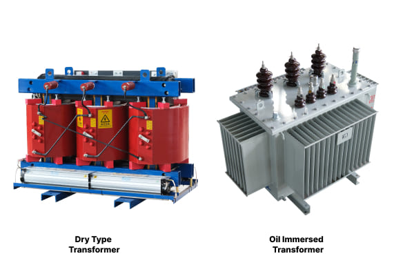
Dry type and oil-filled transformers are two main types of power transformers. They differ in their cooling and insulation methods, with dry types using air and solid materials, while oil-filled types use insulating oil for cooling and insulation.
I’ve worked with both types of transformers throughout my career. Let’s dive into their differences and help you make an informed decision for your specific needs.
What is the difference between dry type and oil transformers?
Have you ever wondered why some transformers are filled with oil while others aren’t? The answer lies in their fundamental design and cooling methods.
The main difference between dry type and oil transformers is their cooling and insulation system. Dry type transformers use air and solid insulating materials, while oil transformers use insulating oil for both cooling and insulation.
In my years of experience with transformer installations, I’ve noticed several key differences between these two types:
Cooling System
-
Dry Type:
- Uses air for cooling
- Often has additional fans for forced air cooling
- Heat dissipates directly into the surrounding air
-
Oil-Filled:
- Uses oil for cooling
- Oil circulates naturally or is forced through cooling radiators
- More efficient at heat dissipation
Insulation
-
Dry Type:
- Uses solid insulating materials like epoxy resin
- No liquid insulation means no risk of leaks
-
Oil-Filled:
- Uses oil as both coolant and insulator
- Oil provides excellent insulation properties
Maintenance
| Aspect | Dry Type | Oil-Filled |
|---|---|---|
| Routine Checks | Less frequent | Regular oil testing required |
| Leak Risk | None | Potential oil leaks |
| Lifespan | 20-30 years | 30-40 years with proper maintenance |
Environmental Considerations
-
Dry Type:
- No oil means no risk of environmental contamination
- Suitable for environmentally sensitive areas
-
Oil-Filled:
- Risk of oil spills
- Requires proper containment measures
Size and Weight
-
Dry Type:
- Generally smaller and lighter
- Easier to install in confined spaces
-
Oil-Filled:
- Larger and heavier due to oil content
- Requires more installation space
In my experience, understanding these differences is crucial for selecting the right transformer for your specific application. Each type has its own strengths and is better suited for certain environments and uses.
What is the advantage of a dry type transformer?
Are you looking for a transformer solution that’s safe, environmentally friendly, and low maintenance? A dry type transformer might be just what you need.
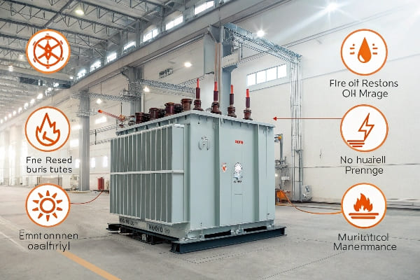
Dry type transformers offer advantages in safety, environmental protection, and maintenance. They have no risk of oil leaks, are fire-resistant, and require less maintenance compared to oil-filled transformers.
Throughout my career, I’ve seen dry type transformers become increasingly popular. Here’s why they’re often preferred:
Safety Benefits
-
Fire Resistance:
- No flammable oil means reduced fire risk
- Ideal for indoor installations and populated areas
-
No Oil Leaks:
- Eliminates the risk of oil spills
- Safer for personnel and equipment around the transformer
Environmental Advantages
-
Eco-Friendly:
- No risk of oil contamination to soil or water
- Easier to dispose of at end of life
-
Indoor Use:
- Can be installed close to the load center
- Reduces the need for long cable runs
Low Maintenance
| Aspect | Benefit |
|---|---|
| No Oil Checks | Eliminates need for regular oil testing |
| Simpler Inspections | Visual checks are straightforward |
| No Oil Handling | Reduces maintenance complexity |
Space Efficiency
-
Compact Design:
- Often smaller than equivalent oil-filled transformers
- Ideal for areas with limited space
-
Flexible Installation:
- Can be installed in various orientations
- No need for oil containment structures
Reliability in Harsh Environments
-
Moisture Resistance:
- Less affected by humid environments
- Suitable for coastal areas or high-humidity locations
-
Altitude Performance:
- Performs well at high altitudes
- No oil to thin out in low-pressure environments
In my experience, dry type transformers are particularly well-suited for:
- Commercial buildings
- Hospitals and healthcare facilities
- Data centers
- Offshore platforms
- Underground installations
Their combination of safety, environmental friendliness, and low maintenance makes them an attractive option for many modern applications. However, it’s important to note that they may have limitations in very high power ratings compared to oil-filled transformers.
What is the advantage of oil-filled transformers?
Are you dealing with high-power applications or looking for a transformer with excellent cooling efficiency? Oil-filled transformers might be your best bet.
Oil-filled transformers excel in high-power applications, offer superior cooling efficiency, and typically have a longer lifespan. They’re also more cost-effective for higher power ratings and can handle overloads better than dry type transformers.
In my years working with power systems, I’ve seen oil-filled transformers dominate in certain areas. Here’s why they’re often preferred:
Superior Cooling Efficiency
-
Oil as Coolant:
- Oil is an excellent heat conductor
- Allows for more efficient cooling of transformer components
-
Natural Circulation:
- Oil naturally circulates as it heats and cools
- Provides passive cooling without additional systems
High Power Capacity
-
Higher Voltage Ratings:
- Can handle much higher voltages than dry type transformers
- Suitable for power transmission and large industrial applications
-
Overload Capability:
- Can handle short-term overloads better
- Oil helps dissipate excess heat during peak loads
Longer Lifespan
| Aspect | Benefit |
|---|---|
| Typical Lifespan | 30-40 years with proper maintenance |
| Insulation Longevity | Oil helps preserve insulation materials |
| Overload Recovery | Better recovery from overload conditions |
Cost-Effectiveness at High Ratings
-
Lower Cost per MVA:
- More economical for high power ratings
- Cost advantage increases with transformer size
-
Established Technology:
- Well-understood manufacturing processes
- Wide availability of parts and service
Noise Reduction
- Oil Dampening:
- Oil helps reduce operational noise
- Beneficial in noise-sensitive environments
Voltage Regulation
- Better Voltage Control:
- Oil provides better insulation properties
- Allows for finer control of voltage regulation
In my experience, oil-filled transformers are particularly well-suited for:
- Power generation plants
- Electrical substations
- Large industrial facilities
- High-voltage power transmission
Their ability to handle high power ratings, coupled with their excellent cooling properties, makes them indispensable in many large-scale electrical systems. However, it’s crucial to consider the maintenance requirements and potential environmental risks associated with oil leaks.
Which is more expensive, a dry type or oil type transformer?
Are you trying to balance your budget with your transformer needs? The cost difference between dry type and oil type transformers isn’t as straightforward as you might think.
Generally, dry type transformers are more expensive upfront for lower power ratings, while oil type transformers become more cost-effective at higher ratings. However, the total cost of ownership depends on factors like maintenance, installation, and operational costs.
In my experience working with various transformer projects, I’ve found that the cost comparison isn’t just about the initial price tag. Let’s break it down:
Initial Purchase Cost
-
Dry Type Transformers:
- More expensive for lower power ratings (up to about 10 MVA)
- Cost increases sharply with power rating
-
Oil Type Transformers:
- More cost-effective for higher power ratings
- Better economies of scale for large transformers
Installation Costs
| Aspect | Dry Type | Oil Type |
|---|---|---|
| Space Requirements | Less space needed | More space for oil containment |
| Weight | Lighter, easier to transport | Heavier, may need special transport |
| Additional Equipment | Minimal | Oil processing equipment needed |
Maintenance Costs
-
Dry Type:
- Lower maintenance costs
- No oil testing or replacement needed
-
Oil Type:
- Higher maintenance costs
- Regular oil testing and potential oil replacement
Operational Costs
-
Dry Type:
- Generally higher losses, especially at lower loads
- May result in higher energy costs over time
-
Oil Type:
- Lower losses, especially at higher loads
- Can lead to energy savings in high-load applications
Lifespan and Replacement
-
Dry Type:
- Typical lifespan of 20-30 years
- May need earlier replacement in harsh environments
-
Oil Type:
- Typical lifespan of 30-40 years with proper maintenance
- Potential for longer service life
Environmental and Safety Considerations
-
Dry Type:
- No oil containment or processing costs
- Lower insurance costs due to reduced fire risk
-
Oil Type:
- Costs for oil containment and potential spill cleanup
- Higher insurance costs due to fire and environmental risks
In my experience, the true cost comparison needs to consider all these factors. For example:
- A dry type transformer might be more expensive upfront but could save money over time in a commercial building due to lower maintenance and insurance costs.
- An oil type transformer could be more cost-effective for a large industrial application where its lower losses and longer lifespan offset the higher maintenance costs.
The key is to analyze your specific needs, including power requirements, installation environment, expected lifespan, and maintenance capabilities. In some cases, I’ve seen the total cost of ownership for a dry type transformer end up lower than an oil type, despite a higher initial cost, due to savings in maintenance and operational costs.
Conclusion
Choosing between dry type and oil-filled transformers depends on your specific needs. Consider factors like power requirements, installation environment, maintenance capabilities, and long-term costs to make the best decision for your project.
Are you struggling with power distribution challenges in your industrial setup? The solution might be simpler than you think.
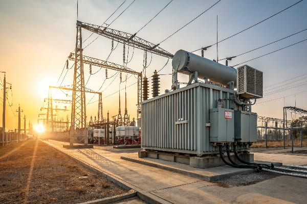
An oil-immersed transformer is a type of electrical transformer that uses oil as a coolant and insulator. It’s designed for high-voltage applications and is known for its efficiency in heat dissipation and electrical insulation.
I’ve seen many industries benefit from oil-immersed transformers. Let’s dive deeper into how these transformers work and why they might be the right choice for your power distribution needs.
Oil-immersed Transformer: Working Principle
Have you ever wondered how these massive transformers manage to handle such high voltages without breaking a sweat? The secret lies in their unique working principle.
Oil-immersed transformers work on the principle of electromagnetic induction, using oil as both a coolant and insulator. The oil surrounds the core and windings, efficiently dissipating heat and providing excellent electrical insulation.
In my years of experience with power systems, I’ve come to appreciate the elegance of oil-immersed transformers. Here’s a deeper look at how they function:
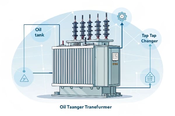
Core Components
The main parts of an oil-immersed transformer include:
- Core: Usually made of laminated silicon steel sheets
- Windings: Primary and secondary coils, typically made of copper
- Insulating Oil: Mineral oil or synthetic alternatives
- Tank: Houses all components and the insulating oil
- Bushings: For connecting external circuits
- Cooling System: Radiators or fans for larger units
Electromagnetic Induction
The basic principle is simple:
- When AC voltage is applied to the primary winding, it creates a changing magnetic field in the core.
- This changing magnetic field induces a voltage in the secondary winding.
- The ratio of primary to secondary turns determines the voltage transformation.
Role of Oil
The oil in these transformers serves multiple crucial functions:
| Function | Description |
|---|---|
| Cooling | Absorbs and dissipates heat from the core and windings |
| Insulation | Provides electrical insulation between components |
| Arc Suppression | Helps quench arcs that may form during operation |
| Moisture Protection | Prevents moisture from degrading the insulation |
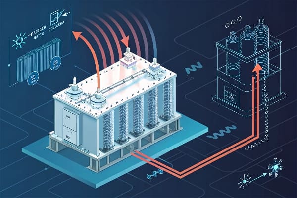
Heat Dissipation
One of the most impressive aspects of oil-immersed transformers is their cooling efficiency:
- As the transformer operates, heat is generated in the core and windings.
- The oil absorbs this heat through direct contact.
- Natural convection circulates the oil, carrying heat to the tank walls.
- For larger transformers, external radiators or forced-air cooling may be used.
In my experience, this cooling system is what allows oil-immersed transformers to handle such high power ratings efficiently.
Types of Oil-Filled Transformers
Are you wondering which type of oil-filled transformer might be best for your specific needs? You’re not alone in this quest.
Oil-filled transformers come in various types, including distribution transformers, power transformers, and specialty transformers. Each type is designed for specific voltage levels, power ratings, and applications, ranging from residential power distribution to large industrial use.
Throughout my career, I’ve worked with various types of oil-filled transformers. Let me break down the main categories for you:
Distribution Transformers
These are the workhorses of the power grid:
- Voltage Range: Typically 34.5 kV and below
- Power Rating: Usually up to 2500 kVA
- Applications: Residential areas, small commercial buildings
- Features: Often pole-mounted or pad-mounted
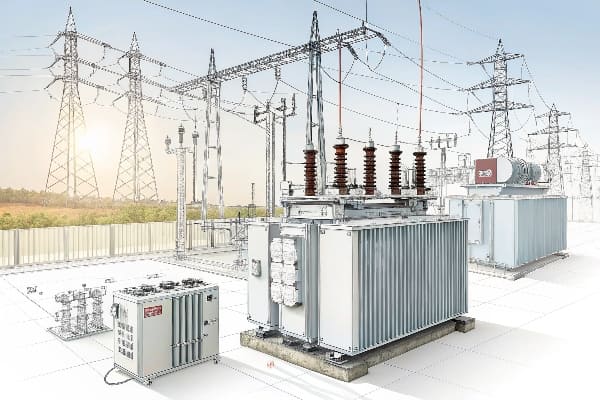
Power Transformers
These handle the heavy lifting in power transmission:
- Voltage Range: Can go up to 765 kV or higher
- Power Rating: From a few MVA to hundreds of MVA
- Applications: Power plants, large industrial facilities, substations
- Features: Usually very large, with advanced cooling systems
Specialty Transformers
These are designed for specific applications:
| Type | Application | Special Features |
|---|---|---|
| Furnace Transformers | Electric arc furnaces | High current output, robust design |
| Rectifier Transformers | DC power supply | Special winding configurations |
| Traction Transformers | Electric railways | Compact design, vibration resistant |
Cooling Methods
The cooling method used can also categorize oil-filled transformers:
- ONAN (Oil Natural Air Natural): Relies on natural oil circulation and air cooling
- ONAF (Oil Natural Air Forced): Uses fans to enhance air cooling
- OFAF (Oil Forced Air Forced): Uses pumps for oil circulation and fans for air cooling
- ODAF (Oil Directed Air Forced): Directs oil flow through windings for more efficient cooling
In my experience, choosing the right type of transformer and cooling method is crucial for optimal performance and longevity.
Maintenance and Safety Considerations for Oil-Immersed Transformers
Are you concerned about keeping your oil-immersed transformer in top shape? You should be – proper maintenance is key to longevity and safety.
Maintaining oil-immersed transformers involves regular oil testing, monitoring for leaks, and periodic inspections. Safety considerations include fire prevention, environmental protection, and proper handling of transformer oil.
Over the years, I’ve learned that a well-maintained transformer is a reliable transformer. Here’s what you need to know about maintenance and safety:
Regular Maintenance Tasks
- Oil Testing: Check oil quality at least annually
- Visual Inspections: Look for leaks, rust, or damage monthly
- Thermal Imaging: Conduct annually to detect hot spots
- Bushing Maintenance: Clean and inspect bushings yearly
- DGA (Dissolved Gas Analysis): Perform annually or as needed
Oil Quality Management
The health of the transformer oil is crucial:
| Test | Frequency | Purpose |
|---|---|---|
| Dielectric Strength | Annually | Ensures insulating properties |
| Acidity | Annually | Checks for oil degradation |
| Moisture Content | Bi-annually | Prevents insulation breakdown |
| Interfacial Tension | Annually | Indicates oil contamination |
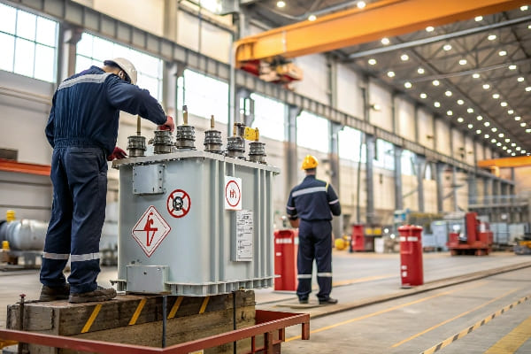
Safety Considerations
Safety should always be your top priority:
- Fire Prevention: Install fire suppression systems
- Spill Containment: Use proper oil containment methods
- Grounding: Ensure proper grounding of the transformer
- Personal Protective Equipment: Use when handling oil or working near transformers
- Emergency Procedures: Have clear protocols for oil leaks or electrical faults
Environmental Concerns
In today’s world, environmental responsibility is crucial:
- Use biodegradable transformer oils when possible
- Have a proper disposal plan for old transformer oil
- Implement spill prevention and response plans
- Consider retrofilling with more environmentally friendly oils
Predictive Maintenance
I’ve found that predictive maintenance can save a lot of trouble:
- Online Monitoring: Use sensors for real-time data on key parameters
- Trend Analysis: Track oil quality and electrical parameters over time
- Acoustic Monitoring: Detect partial discharges early
- Load Analysis: Ensure the transformer isn’t consistently overloaded
In my experience, a comprehensive maintenance and safety program not only extends the life of your transformer but also prevents costly downtime and potential environmental incidents.
Conclusion
Oil-immersed transformers are vital for efficient power distribution. With proper maintenance and safety measures, they offer reliable performance and longevity. Understanding their types and care needs is key to maximizing their benefits in various applications.
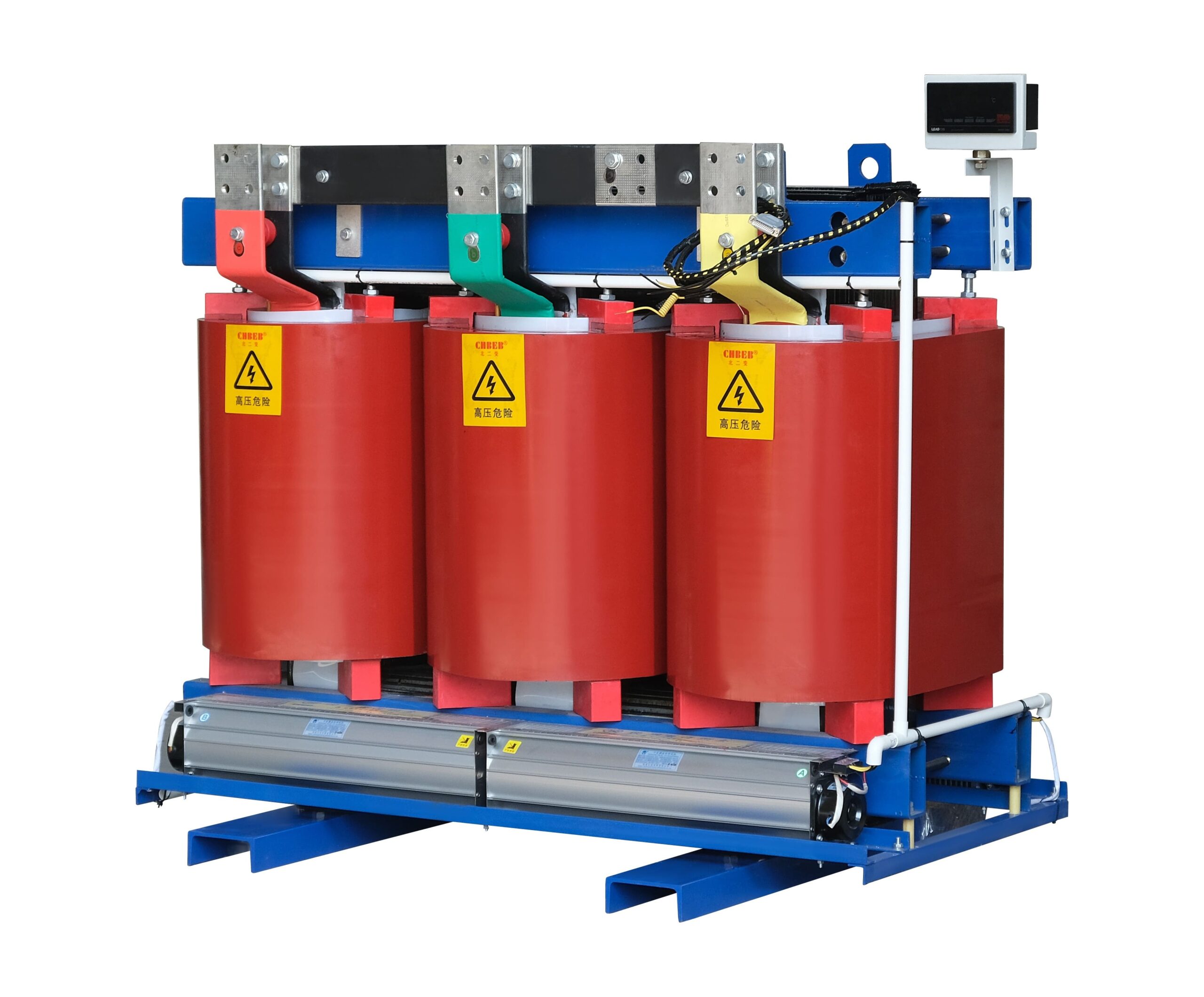
Are you tired of worrying about oil leaks and fire hazards in your electrical system? There’s a solution that might put your mind at ease.
A dry type transformer is an electrical transformer that uses air as its cooling medium instead of oil. It’s designed for indoor use, offering enhanced safety, reduced maintenance, and environmental benefits compared to traditional oil-filled transformers.
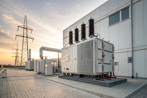
Let’s dive deeper into the world of dry type transformers and discover why they might be the perfect fit for your electrical needs.
What is a dry type transformer used for?
Have you ever wondered how large buildings manage their complex electrical systems safely? The answer often lies in dry type transformers.
Dry type transformers are used in various applications where safety, reliability, and environmental concerns are paramount. They’re commonly found in commercial buildings, industrial facilities, renewable energy systems, and areas where fire safety is critical.

Common Applications
In my years of experience with transformer installations, I’ve seen dry type transformers used in numerous settings:
- Commercial Buildings: Office complexes, shopping malls, and hotels often use dry type transformers due to their safety features and low maintenance requirements.
- Healthcare Facilities: Hospitals and clinics prefer dry type transformers for their reliability and reduced fire risk.
- Educational Institutions: Schools and universities use them to ensure a safe environment for students and staff.
- Industrial Plants: Many factories and processing plants choose dry type transformers for their durability and ability to withstand harsh environments.
Specific Use Cases
Let’s break down some specific scenarios where dry type transformers shine:
| Application | Reason for Use |
|---|---|
| Data Centers | Low fire risk, high reliability |
| Offshore Platforms | Compact size, no risk of oil spills |
| Renewable Energy | Used in wind turbines and solar installations |
| Underground Facilities | No oil leakage concerns |
Technical Advantages
Dry type transformers offer several technical benefits that make them suitable for these applications:
- Voltage Regulation: They provide excellent voltage regulation, which is crucial for sensitive electronic equipment.
- Overload Capacity: Many dry type transformers can handle short-term overloads without significant degradation.
- Noise Reduction: They generally operate more quietly than oil-filled transformers, making them ideal for indoor use.
- Customization: Dry type transformers can be easily customized for specific voltage requirements and installation constraints.
Environmental Considerations
The environmental benefits of dry type transformers are significant:
- No Oil: There’s no risk of oil leaks or spills, which can be environmentally damaging.
- Recyclability: At the end of their life, dry type transformers are easier to recycle than oil-filled ones.
- Energy Efficiency: Many modern dry type transformers are designed for high energy efficiency, reducing overall power consumption.
What is the life expectancy of a dry type transformer?
Are you wondering if investing in a dry type transformer is worth it in the long run? Let’s talk about their durability and longevity.
The life expectancy of a dry type transformer typically ranges from 20 to 30 years, with some well-maintained units lasting even longer. This longevity depends on factors such as operating conditions, maintenance practices, and environmental factors.
Factors Affecting Lifespan
From my experience, several key factors influence the life expectancy of dry type transformers:
- Operating Temperature: Excessive heat can degrade insulation materials over time.
- Load Profile: Consistent overloading can shorten the transformer’s life.
- Environmental Conditions: Humidity, dust, and chemical contaminants can affect performance and longevity.
- Maintenance Practices: Regular inspections and proper care can significantly extend a transformer’s life.
Lifespan Comparison
Let’s compare the lifespan of dry type transformers with other types:
| Transformer Type | Average Lifespan | Factors Influencing Lifespan |
|---|---|---|
| Dry Type | 20-30 years | Temperature, load, environment |
| Oil-Filled | 30-40 years | Oil quality, maintenance |
| Cast Resin | 25-35 years | Environmental conditions |
Maintenance for Longevity
To maximize the life of a dry type transformer, I recommend the following maintenance practices:
- Regular Inspections: Conduct visual inspections at least annually.
- Cleaning: Remove dust and debris that can impede cooling.
- Temperature Monitoring: Install temperature sensors to prevent overheating.
- Load Management: Avoid prolonged overloading situations.
- Environmental Control: Ensure proper ventilation and humidity control in the installation area.
Signs of Aging
It’s important to recognize signs that a dry type transformer is nearing the end of its life:
- Increased Noise: Unusual buzzing or humming can indicate deteriorating insulation.
- Higher Operating Temperatures: If the transformer runs hotter than usual, it may be losing efficiency.
- Visible Damage: Cracks or discoloration on insulation materials are red flags.
- Decreased Performance: If voltage regulation becomes poor, it might be time for replacement.
Economic Considerations
When considering the lifespan of a dry type transformer, it’s crucial to think about the total cost of ownership:
- Initial Investment: Dry type transformers may have a higher upfront cost.
- Operational Costs: They often have lower losses, reducing energy costs over time.
- Maintenance Expenses: Generally lower than oil-filled transformers due to simpler maintenance requirements.
- Replacement Planning: Factor in the cost of replacement when the transformer reaches the end of its life.
Why are dry type transformers more popular?
Are you curious about the growing trend in electrical systems? Dry type transformers are gaining ground, and for good reasons.
Dry type transformers are becoming more popular due to their safety features, environmental benefits, low maintenance requirements, and suitability for indoor installations. They offer a compelling combination of reliability, efficiency, and reduced fire risk.
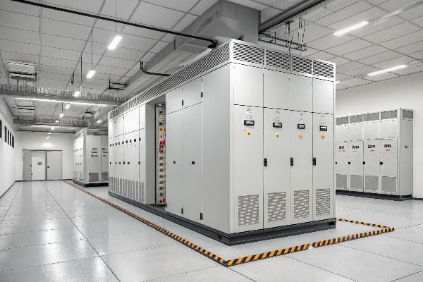
Safety Advantages
Safety is a top priority in any electrical system, and dry type transformers excel in this area:
- Fire Resistance: With no oil, the risk of fire is significantly reduced.
- No Leakage Risk: There’s no chance of oil leaks, which can be hazardous and environmentally damaging.
- Indoor Use: They can be safely installed close to the load center, even in populated areas.
Environmental Benefits
In today’s eco-conscious world, the environmental advantages of dry type transformers are hard to ignore:
| Aspect | Benefit |
|---|---|
| No Oil | Eliminates risk of soil and water contamination |
| Recyclability | Easier to recycle at end of life |
| Energy Efficiency | Many models offer high efficiency, reducing energy consumption |
Maintenance Simplicity
As someone who has worked with various transformer types, I can attest to the maintenance benefits of dry type transformers:
- No Oil Checks: There’s no need for regular oil testing or replacement.
- Simpler Inspections: Visual inspections are straightforward and don’t require specialized equipment.
- Reduced Downtime: Maintenance can often be performed without taking the transformer offline.
Space Efficiency
Dry type transformers offer significant advantages in terms of space utilization:
- Compact Design: They often have a smaller footprint than equivalent oil-filled transformers.
- Flexible Installation: Can be installed in various orientations, including vertically.
- No Fire Walls: In many cases, expensive fire walls are not required, saving space and cost.
Regulatory Compliance
The increasing popularity of dry type transformers is partly driven by regulatory factors:
- Stricter Fire Codes: Many jurisdictions have tightened fire safety regulations, favoring dry type transformers.
- Environmental Regulations: Concerns about oil spills have led to preferences for oil-free alternatives.
- Energy Efficiency Standards: Some dry type transformers meet or exceed new efficiency standards more easily.
Cost Considerations
While the initial cost may be higher, dry type transformers often prove economical in the long run:
- Lower Installation Costs: No need for oil containment systems or extensive fire suppression.
- Reduced Insurance Premiums: The lower fire risk can lead to savings on insurance.
- Energy Savings: Higher efficiency models can significantly reduce energy costs over time.
Technological Advancements
Recent improvements have made dry type transformers even more attractive:
- Enhanced Cooling Systems: Better heat dissipation allows for higher power ratings.
- Improved Insulation Materials: Modern materials offer better performance and longevity.
- Smart Monitoring: Integration with digital monitoring systems for predictive maintenance.
Conclusion
Dry type transformers offer a safe, efficient, and environmentally friendly solution for modern electrical systems. Their growing popularity is driven by safety benefits, low maintenance needs, and suitability for diverse applications, making them a smart choice for many installations.
Are you worried about the safety and efficiency of your power distribution system? The answer might be right under your feet.
Grounding a power transformer is a critical safety measure that protects equipment, personnel, and ensures proper system operation. It provides a path for fault currents, stabilizes voltage levels, and helps in detecting and clearing faults quickly.
Let’s dig deeper into the world of transformer grounding and uncover why it’s so important for your electrical systems.
What happens if a transformer is not grounded?
Imagine a ticking time bomb in your electrical system. That’s what an ungrounded transformer can be.
An ungrounded transformer can lead to dangerous voltage spikes, increased risk of electrical shock, difficulty in fault detection, and potential equipment damage. It can also cause system instability and compromise the overall safety of the electrical installation.
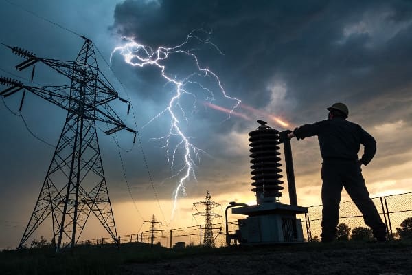
Safety Risks
In my years of experience with transformer installations, I’ve seen firsthand the dangers of ungrounded systems:
- Electrical Shock Hazard: Without a proper ground, the transformer’s metal parts can become energized, posing a serious risk to anyone who comes in contact with them.
- Arc Flash Risk: Ungrounded systems are more prone to arc flash incidents, which can cause severe burns and equipment damage.
- Fire Hazard: Undetected faults in ungrounded systems can lead to overheating and potentially start fires.
Operational Issues
Ungrounded transformers can also cause several operational problems:
| Issue | Description |
|---|---|
| Voltage Instability | Lack of a reference point can lead to unpredictable voltage fluctuations |
| Fault Detection Difficulty | Without a ground path, it’s harder to detect and locate faults in the system |
| Overvoltage Stress | Transient overvoltages can stress insulation and lead to premature equipment failure |
System Reliability
The reliability of your entire electrical system can be compromised when transformers are not properly grounded:
- Intermittent Faults: Ungrounded systems may allow intermittent faults to persist, leading to mysterious outages and hard-to-diagnose problems.
- Equipment Lifespan: The stress on insulation and components in an ungrounded system can shorten the lifespan of expensive electrical equipment.
- Power Quality Issues: Ungrounded systems are more susceptible to power quality problems like harmonics and voltage distortions.
Why do we ground neutral in power transformers?
Have you ever wondered why that extra wire is so important? The neutral grounding in power transformers is more than just an afterthought.
We ground the neutral in power transformers to establish a reference point for voltage measurements, provide a return path for unbalanced loads, limit overvoltages, and facilitate fault detection and clearing. It’s a crucial aspect of system safety and stability.
Voltage Stabilization
Grounding the neutral helps stabilize the voltage in the system:
- Reference Point: It provides a zero-voltage reference point for the system.
- Phase Balance: It helps maintain balance between phase voltages.
- Overvoltage Protection: It limits the voltage rise on healthy phases during ground faults.
Fault Management
In my experience, neutral grounding significantly improves fault management:
| Aspect | Benefit |
|---|---|
| Fault Detection | Makes it easier to detect ground faults |
| Fault Clearing | Provides a path for fault current, enabling protective devices to operate |
| System Protection | Helps in limiting fault currents to manageable levels |
Load Balancing
Neutral grounding also plays a role in load management:
- Unbalanced Loads: It provides a return path for current in systems with unbalanced loads.
- Harmonic Currents: It can help in managing harmonic currents in the system.
- Single-Phase Loads: It allows for the connection of single-phase loads in a three-phase system.
Safety Enhancement
The safety benefits of neutral grounding cannot be overstated:
- Touch Voltage Reduction: It helps limit the voltage that a person might contact during a fault.
- Equipment Protection: It provides a path for surge currents, protecting equipment from damage.
- Consistent Operation: It ensures consistent and predictable system behavior, which is crucial for safety planning.
Do you ground both sides of a transformer?
Is double grounding necessary, or is it overkill? Let’s explore the grounding requirements for transformers.
In most cases, both the primary and secondary sides of a transformer should be grounded. However, the specific grounding requirements can vary depending on the transformer type, system configuration, and local electrical codes.
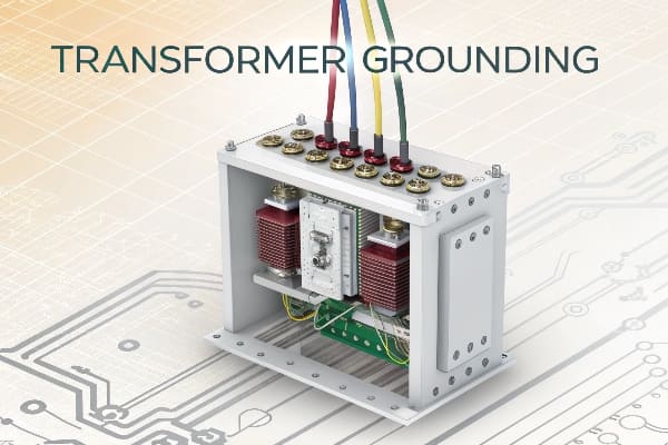
Primary Side Grounding
Grounding the primary side of a transformer is crucial:
- System Grounding: It’s often part of the overall power system grounding scheme.
- Fault Protection: It provides a path for primary-side fault currents.
- Overvoltage Protection: It helps protect against lightning strikes and switching surges.
Secondary Side Grounding
The secondary side grounding is equally important:
| Reason | Explanation |
|---|---|
| Safety | Ensures that the secondary voltage is referenced to ground |
| Fault Clearing | Enables proper operation of overcurrent protection devices |
| Code Compliance | Often required by electrical codes for certain voltage levels |
Special Cases
In my years of working with transformers, I’ve encountered several special cases:
- Isolation Transformers: These may have an ungrounded secondary to provide isolation.
- Auto-transformers: They typically have a common grounding point for both primary and secondary.
- Delta-Wye Transformers: The Wye side is usually grounded, while the Delta side may remain ungrounded.
Grounding Considerations
When deciding on grounding both sides, consider:
- System Voltage: Higher voltage systems often require more comprehensive grounding.
- Transformer Size: Larger transformers may have more complex grounding requirements.
- Application: The specific use of the transformer can influence grounding needs.
- Local Regulations: Always comply with local electrical codes and standards.
How to ground a power transformer?
Are you ready to ensure your transformer is safely grounded? Let’s walk through the process step by step.
Grounding a power transformer involves connecting the transformer’s neutral point or tank to the earth. This is typically done using a low-resistance connection to a grounding electrode system, following specific procedures and standards to ensure safety and effectiveness.
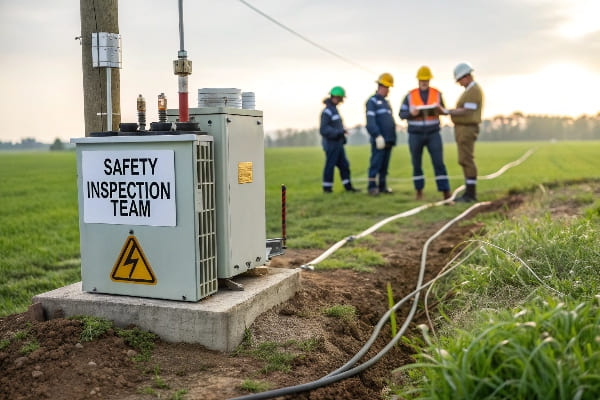
Grounding Components
To properly ground a transformer, you’ll need:
- Grounding Electrode: Usually a copper rod driven into the earth.
- Grounding Conductor: A copper wire connecting the transformer to the electrode.
- Grounding Clamps: To secure connections between components.
- Ground Test Meter: To verify the quality of the ground connection.
Step-by-Step Process
Here’s a basic process I follow when grounding a transformer:
| Step | Description |
|---|---|
| 1. Site Preparation | Clear the area and identify the best location for the ground rod |
| 2. Install Ground Rod | Drive the grounding electrode into the earth to the required depth |
| 3. Connect Grounding Wire | Attach the grounding conductor to the transformer’s grounding point |
| 4. Secure Connections | Use appropriate clamps to ensure solid connections |
| 5. Test the Ground | Measure the ground resistance to ensure it meets standards |
Safety Precautions
Safety is paramount when grounding transformers:
- De-energize: Always work on de-energized equipment.
- Personal Protective Equipment: Wear appropriate PPE, including insulated gloves and safety glasses.
- Proper Tools: Use insulated tools rated for the voltage level of the transformer.
- Verify: Double-check all connections before re-energizing the transformer.
Compliance and Standards
It’s crucial to follow relevant standards and regulations:
- National Electrical Code (NEC): In the U.S., follow NEC guidelines for grounding.
- IEEE Standards: Adhere to IEEE recommendations for power system grounding.
- Local Codes: Always comply with local electrical codes and utility requirements.
- Manufacturer Guidelines: Follow the transformer manufacturer’s specific grounding instructions.
Maintenance and Inspection
Grounding systems require ongoing attention:
- Regular Inspections: Visually inspect grounding connections periodically.
- Resistance Testing: Conduct annual ground resistance tests.
- Corrosion Prevention: Apply anti-corrosion compounds to exposed connections.
- Documentation: Keep records of all grounding work and test results.
Conclusion
Proper grounding of power transformers is crucial for safety, system stability, and efficient operation. By understanding and implementing correct grounding practices, we can ensure reliable and safe power distribution systems.
Are you tired of high energy bills and inefficient power distribution? The solution might be closer than you think.
An amorphous alloy transformer is a highly efficient electrical device that uses cores made from amorphous metal alloys instead of traditional crystalline materials. It offers significant energy savings and improved performance in power distribution systems.
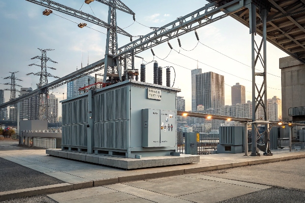
Let’s dive deeper into this innovative technology and explore how it’s changing the landscape of power distribution.
What is the amorphous transformer?
Have you ever wondered how we could make our power systems more efficient? The answer might lie in amorphous transformers.
An amorphous transformer is a type of electrical transformer that uses a core made of amorphous metal alloys. These transformers are known for their high efficiency and low energy losses compared to traditional transformers.
Key Features of Amorphous Transformers
Amorphous transformers have several unique features that set them apart from conventional transformers:
- Core Material: The core is made of amorphous metal alloys, which have a disordered atomic structure.
- Energy Efficiency: They have 40-70% lower core losses compared to traditional silicon steel transformers.
- Magnetic Properties: Amorphous alloys have excellent magnetic properties, particularly low hysteresis and eddy current losses.
Applications of Amorphous Transformers
Amorphous transformers are widely used in various applications:
| Application | Benefit |
|---|---|
| Distribution Transformers | Reduced energy losses in power distribution networks |
| Power Transformers | Improved efficiency in power transmission |
| Current Transformers | Enhanced accuracy in current measurement |
Advantages Over Traditional Transformers
In my experience working with various transformer types, I’ve found that amorphous transformers offer several advantages:
- Energy Savings: The reduced core losses translate to significant energy savings over the transformer’s lifetime.
- Environmental Impact: Lower energy consumption means reduced carbon emissions.
- Noise Reduction: Amorphous cores typically produce less noise during operation.
- Compact Size: Despite their high efficiency, these transformers can be designed to be more compact.
What is amorphous alloy?
Have you ever heard of a metal that’s not quite solid and not quite liquid? That’s the fascinating world of amorphous alloys.
An amorphous alloy is a metallic material with a disordered atomic-scale structure. Unlike crystalline alloys, amorphous alloys don’t have a regular, repeating arrangement of atoms, giving them unique properties.
Structure of Amorphous Alloys
To understand amorphous alloys, we need to look at their structure:
- Atomic Arrangement: In amorphous alloys, atoms are arranged randomly, similar to the structure of glass.
- Rapid Cooling: They are formed by rapidly cooling molten metal, preventing the atoms from arranging into a crystalline structure.
- Metastable State: Amorphous alloys are in a metastable state, meaning they can crystallize under certain conditions.
Properties of Amorphous Alloys
Amorphous alloys have several unique properties that make them valuable in various applications:
| Property | Description |
|---|---|
| Magnetic Properties | Low coercivity and high permeability |
| Mechanical Strength | High strength and hardness |
| Corrosion Resistance | Excellent resistance to chemical corrosion |
| Electrical Properties | High electrical resistivity |
Applications of Amorphous Alloys
In my work with electrical equipment, I’ve seen amorphous alloys used in various applications:
- Transformer Cores: As we’ve discussed, they’re excellent for reducing energy losses.
- Magnetic Sensors: Their unique magnetic properties make them ideal for sensitive magnetic sensors.
- Sporting Goods: Some high-end golf club heads use amorphous alloys for their strength and elasticity.
- Electronic Devices: They’re used in some electronic components for their magnetic and electrical properties.
What are the downsides of using amorphous metal?
While amorphous metals offer many benefits, it’s important to consider their limitations. Are they truly a perfect solution?
Despite their advantages, amorphous metals have some drawbacks. These include higher production costs, limitations in size and shape, potential for crystallization over time, and challenges in machining and joining.
Production Challenges
From my experience in the transformer industry, I’ve observed several challenges in working with amorphous metals:
- Cost: The production process for amorphous metals is more complex and expensive than for traditional crystalline metals.
- Size Limitations: It’s difficult to produce large pieces of amorphous metal, which can limit their applications.
- Shape Restrictions: The rapid cooling required to form amorphous metals limits the shapes that can be produced.
Material Properties Concerns
While amorphous metals have many beneficial properties, they also have some drawbacks:
| Property | Concern |
|---|---|
| Thermal Stability | May crystallize at high temperatures |
| Brittleness | Can be more brittle than crystalline counterparts |
| Magnetic Saturation | Lower magnetic saturation than some crystalline materials |
Processing Difficulties
Working with amorphous metals presents several challenges:
- Machining: Amorphous metals are often harder and more brittle than crystalline metals, making them difficult to machine.
- Joining: Traditional welding techniques can cause crystallization, so special joining methods are often required.
- Heat Treatment: Heat treatment, often used to modify the properties of crystalline metals, can cause amorphous metals to crystallize.
Economic Considerations
In my dealings with clients, I’ve found that the economic aspects of amorphous metals can be a significant concern:
- Initial Cost: The higher production cost of amorphous metals often translates to a higher initial cost for equipment like transformers.
- Long-term Savings: While the initial cost is higher, the energy savings over time can offset this. However, this requires a long-term perspective that not all customers have.
- Market Acceptance: Despite their benefits, some industries are slow to adopt new technologies, preferring tried-and-tested crystalline materials.
What alloy is used in transformers?
When it comes to transformers, the choice of alloy can make a big difference in performance. So, what’s the best option?
Transformers typically use silicon steel (also known as electrical steel) for their cores. However, amorphous metal alloys, usually iron-based with additions of elements like boron, silicon, and phosphorus, are increasingly used for their superior magnetic properties.
Traditional Transformer Alloys
In my years of experience in the transformer industry, I’ve worked with various alloys:
- Silicon Steel: This is the most common alloy used in transformer cores. It’s an iron alloy with silicon content typically ranging from 3% to 6.5%.
- Grain-Oriented Silicon Steel: This is a specialized type of silicon steel with grains aligned in the rolling direction, offering better magnetic properties in that direction.
- Non-Oriented Silicon Steel: This type has more uniform magnetic properties in all directions, making it suitable for rotating electrical machines.
Amorphous Alloys for Transformers
More recently, I’ve seen a shift towards amorphous alloys in transformer cores:
| Alloy Composition | Advantages |
|---|---|
| Fe-B-Si | High magnetic permeability, low core losses |
| Fe-B-Si-C | Improved thermal stability |
| Fe-B-P | Enhanced glass-forming ability |
Comparison of Transformer Alloys
Let’s compare the properties of traditional and amorphous alloys:
- Core Losses: Amorphous alloys typically have 70-80% lower core losses than conventional silicon steel.
- Saturation Induction: Silicon steel generally has higher saturation induction, allowing for smaller core sizes.
- Cost: Amorphous alloys are more expensive to produce but can lead to energy savings over time.
- Manufacturability: Silicon steel is easier to work with in terms of cutting, stacking, and assembling transformer cores.
Future Trends in Transformer Alloys
Based on my observations of industry trends, I believe we’ll see:
- Continued Development: Ongoing research into new amorphous alloy compositions with even better magnetic properties.
- Hybrid Designs: Some manufacturers are exploring cores that combine amorphous and nanocrystalline materials to optimize performance.
- Improved Manufacturing: Advancements in production techniques for amorphous alloys, potentially reducing costs and expanding their use.
Conclusion
Amorphous alloy transformers represent a significant advancement in energy efficiency. While they face some challenges, their benefits in energy savings and environmental impact make them a promising technology for the future of power distribution.
