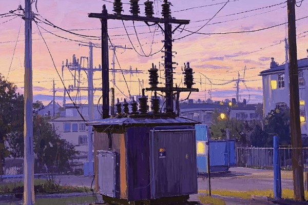
Have you ever wondered why some neighborhoods have big green boxes on the ground while others have transformers hanging on poles? The choice between these two can greatly impact urban living.
Pad mount transformers are generally more efficient for urban areas compared to pole mount transformers. They offer better space utilization, enhanced safety, improved aesthetics, and easier maintenance access. However, the choice depends on specific urban layout, cost considerations, and local regulations.
As someone who’s worked in urban power distribution for years, I’ve seen firsthand how the right transformer choice can make or break a city’s electrical infrastructure. Let’s dive into the details of pad mount and pole mount transformers to understand which one might be the best fit for your urban area.
What Are Pad Mount and Pole Mount Transformers? A Quick Overview
When I first started in this industry, I was confused by the variety of transformers out there. But understanding the basics is crucial for anyone involved in urban planning or electrical engineering.
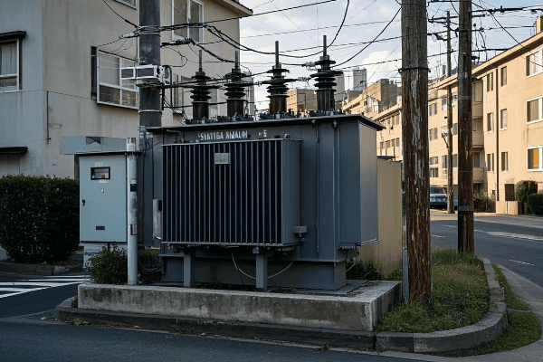
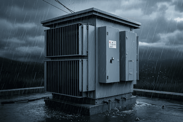
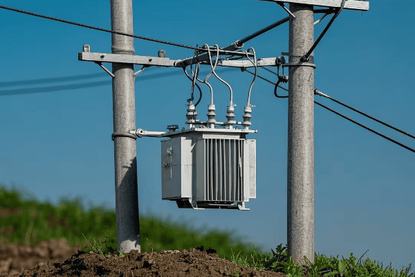
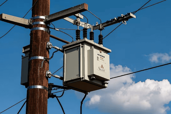
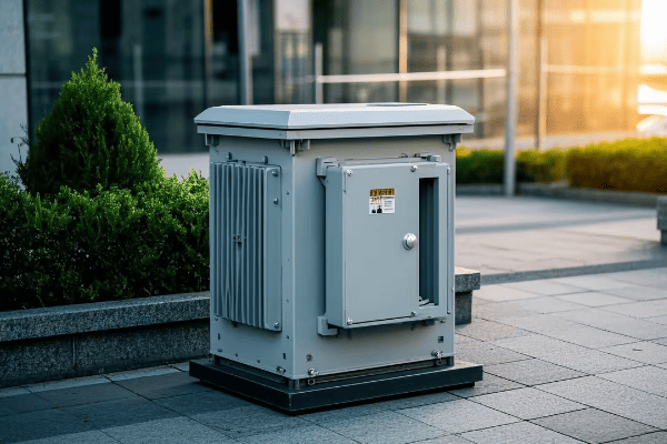
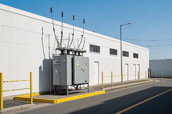
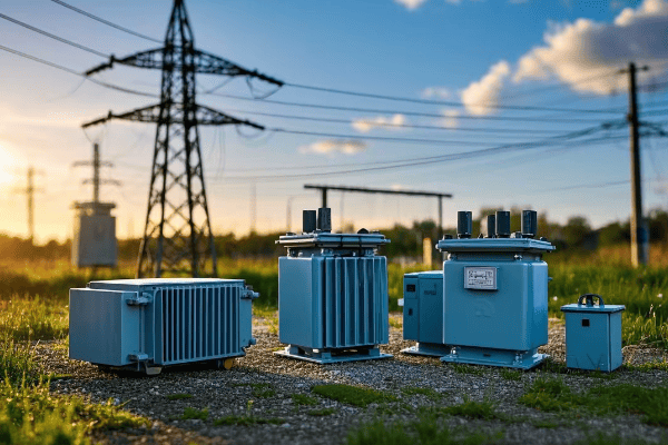
Pad mount transformers are ground-level units enclosed in metal cabinets, typically seen as green boxes in residential areas. Pole mount transformers are mounted on utility poles. Both types step down high voltage electricity to levels suitable for end-users, but their design and placement differ significantly.
Let’s break down the key characteristics of each:
Pad Mount Transformers
- Location: Ground level
- Enclosure: Metal cabinet, often green
- Size: Larger footprint, but lower profile
- Typical Use: Residential areas, commercial zones
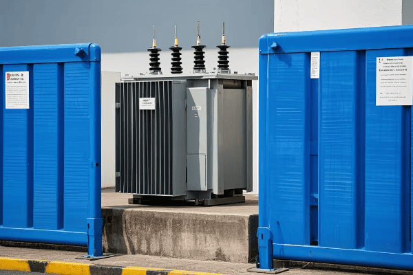
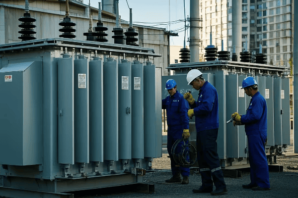
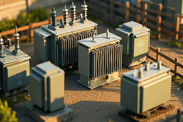
Pole Mount Transformers
- Location: Elevated on utility poles
- Enclosure: Open to air, with minimal covering
- Size: Smaller footprint, but more visible
- Typical Use: Rural areas, older urban neighborhoods
I remember a project where we were upgrading a suburban area’s electrical system. The neighborhood had a mix of old pole mount transformers and newer pad mount units. The contrast was striking – the areas with pad mounts had a cleaner, more modern look, while the pole mounts gave a more traditional, industrial feel.
Here’s a quick comparison table:
| Feature | Pad Mount | Pole Mount |
|---|---|---|
| Installation | Ground level | Elevated on poles |
| Aesthetics | Less visible | More visible |
| Space Required | More ground space | Less ground space |
| Accessibility | Easy ground access | Requires climbing |
| Safety | Enclosed, tamper-resistant | Open, potential climbing hazard |
| Typical Capacity | Higher | Lower |
The choice between pad mount and pole mount transformers often comes down to more than just technical specifications. In urban areas, factors like space availability, local regulations, and even community preferences play a big role.
Key Differences Between Pad Mount and Pole Mount Transformers
When I first started comparing these two types of transformers, I was amazed at how two devices with the same basic function could be so different in their design and application.
The key differences between pad mount and pole mount transformers lie in their installation, safety features, capacity, and visual impact. Pad mount transformers offer higher capacity and better safety features but require more ground space. Pole mount transformers are more visible but take up less ground space and are often cheaper to install.
Let’s dive deeper into these differences:
1. Installation and Space Requirements
Pad Mount:
- Requires a concrete pad at ground level
- Takes up more ground space
- Easier to install in areas with underground utilities
Pole Mount:
- Mounted on existing or new utility poles
- Minimal ground footprint
- Requires overhead power lines
2. Safety Features
Pad Mount:
- Enclosed in tamper-resistant cabinets
- Less exposed to weather elements
- Reduced risk of public contact
Pole Mount:
- More exposed to elements
- Potential climbing hazard
- Higher risk of animal interference
3. Capacity and Scalability
Pad Mount:
- Generally higher capacity (up to 5000 kVA)
- Easier to upgrade or replace
- Better suited for growing power demands
Pole Mount:
- Typically lower capacity (up to 167 kVA)
- More challenging to upgrade
- Limited by pole strength and space
Here’s a detailed comparison table:
| Feature | Pad Mount | Pole Mount |
|---|---|---|
| Installation Location | Ground level | Elevated on poles |
| Ground Space Required | More | Less |
| Visual Impact | Low | High |
| Typical Capacity Range | 75 kVA – 5000 kVA | 10 kVA – 167 kVA |
| Safety Enclosure | Fully enclosed | Partially open |
| Weather Protection | High | Moderate |
| Maintenance Accessibility | Easy | Challenging |
| Installation Cost | Higher | Lower |
| Scalability | Easier to upgrade | Limited by pole capacity |
| Typical Lifespan | 30-40 years | 20-30 years |
I recall a project in a rapidly growing suburban area where we initially installed pole mount transformers due to budget constraints. However, as the power demand increased, we found ourselves constantly upgrading and replacing these units. Eventually, we switched to pad mount transformers, which, despite the higher initial cost, proved more cost-effective in the long run due to their higher capacity and easier upgradability.
Space Efficiency: How Pad Mount Transformers Optimize Urban Land Use
In my years of working on urban power projects, I’ve seen how valuable every square foot of land can be. This is where pad mount transformers really shine in optimizing urban land use.
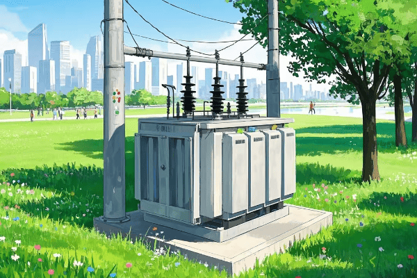
Pad mount transformers optimize urban land use by having a lower profile and integrating seamlessly with landscaping. While they require more ground space than pole mounts, their compact design allows for creative placement options. This efficiency is crucial in dense urban areas where space is at a premium.
Let’s explore how pad mount transformers contribute to space efficiency in urban settings:
1. Compact Design and Integration
Pad mount transformers are designed to blend into their surroundings:
- Low profile allows for easy concealment with shrubs or fencing
- Can be incorporated into urban design elements like planters or seating areas
- Eliminates the need for overhead lines, freeing up vertical space
2. Underground Utility Compatibility
Pad mounts work well with underground utility systems:
- Aligns with modern urban planning trends of burying power lines
- Reduces clutter in the urban skyline
- Allows for more efficient use of above-ground space
3. Flexible Placement Options
The ground-level installation offers various placement possibilities:
- Can be installed in alleys, along property lines, or in dedicated utility areas
- Multiple units can be grouped together in larger developments
- Easier to plan around in new construction projects
Here’s a comparison of space utilization:
| Aspect | Pad Mount | Pole Mount |
|---|---|---|
| Ground Footprint | Larger (typically 4-6 sq ft) | Smaller (pole base only) |
| Vertical Space Used | Minimal (3-5 ft high) | Significant (20-40 ft high) |
| Clearance Requirements | Minimal surrounding space | Large clearance around pole |
| Integration with Landscaping | Easy | Challenging |
| Impact on Usable Land | Can be incorporated into unusable spaces | Pole placement can disrupt land use |
One project that stands out in my memory involved a high-density residential development. We used pad mount transformers placed strategically around the complex. By integrating them into small garden areas, we not only provided the necessary power but also created pleasant green spaces for residents. This dual-use approach was a hit with both the developers and the city planners.
Safety Considerations: Comparing Pad Mount vs. Pole Mount in Urban Settings
Safety is always my top priority when working on any electrical project, especially in busy urban areas. The choice between pad mount and pole mount transformers can significantly impact public safety.
Pad mount transformers generally offer better safety features in urban settings compared to pole mount transformers. They have tamper-resistant enclosures, are less exposed to weather and accidents, and reduce the risk of electrical hazards. However, pole mount transformers have their own safety advantages, particularly in flood-prone areas.
Let’s dive into the safety aspects of both types:
Pad Mount Transformer Safety Features
-
Tamper-Resistant Enclosures
- Locked metal cabinets prevent unauthorized access
- Reduces risk of vandalism and accidental contact
-
Ground-Level Installation
- Eliminates climbing hazards associated with pole mounts
- Easier to secure and monitor
-
Weather Protection
- Enclosed design protects against rain, snow, and debris
- Less susceptible to damage from storms
Pole Mount Transformer Safety Aspects
-
Elevation Advantages
- Less vulnerable to flooding
- Reduced risk of vehicle collisions
-
Visibility
- Easier to spot issues from a distance
- Can be quickly identified in emergency situations
-
Isolation
- Physical distance from public areas
- Less likely to be tampered with by pedestrians
Here’s a safety comparison table:
| Safety Aspect | Pad Mount | Pole Mount |
|---|---|---|
| Public Access | Limited by enclosure | Limited by height |
| Weather Exposure | Low | High |
| Flood Risk | Higher | Lower |
| Vandalism Risk | Low (if properly secured) | Low (due to height) |
| Vehicle Collision Risk | Present but can be mitigated | Low |
| Electrical Shock Risk | Low (enclosed) | Higher (more exposed) |
| Fire Containment | Better | Limited |
| Emergency Access | Easy | Requires climbing equipment |
In my years of experience, I’ve encountered various safety scenarios. For instance, in a flood-prone area, we opted for pole mounts to keep the equipment above potential water levels. This decision proved wise during a severe flood season.
Aesthetic Impact: Which Transformer Type Blends Better with Urban Landscapes?
In my years of working on urban electrical projects, I’ve learned that the visual impact of infrastructure can be just as important as its technical function. The choice between pad mount and pole mount transformers can significantly affect the look and feel of an urban area.
Pad mount transformers generally blend better with urban landscapes compared to pole mount transformers. Their low profile and ability to be concealed or integrated into urban design elements make them less visually intrusive. Pole mount transformers, while more visible, can sometimes complement the aesthetic of certain urban areas, particularly in historic districts.
Let’s explore the aesthetic considerations for both types:
Pad Mount Transformers
-
Low Visual Profile
- Can be easily hidden behind landscaping
- Often painted to blend with surroundings
-
Integration with Urban Design
- Can be incorporated into street furniture or public art
- Allows for creative urban planning solutions
-
Reduction of Overhead Clutter
- Eliminates need for visible overhead lines
- Creates cleaner skylines in urban areas
Pole Mount Transformers
-
Traditional Urban Look
- Can contribute to a nostalgic or historic feel in some areas
- Part of the familiar urban infrastructure
-
Vertical Space Utilization
- Keeps ground space clear for other uses
- Can be combined with street lighting or signage
-
Visibility for Maintenance
- Easier to spot and access for repairs
- Can serve as landmarks for utility workers
Here’s an aesthetic comparison table:
| Aesthetic Aspect | Pad Mount | Pole Mount |
|---|---|---|
| Visual Impact | Low | High |
| Ability to Conceal | High | Low |
| Integration with Landscaping | Easy | Challenging |
| Skyline Impact | Minimal | Significant |
| Flexibility in Design | High | Limited |
| Historical Compatibility | Varies | Often preferred in historic areas |
I once worked on a project in a newly developed urban area where we used pad mount transformers designed to look like modern art installations. The local community loved how these functional pieces also served as interesting visual elements in their neighborhood parks.
Maintenance and Accessibility: Pad Mount vs. Pole Mount in City Environments
Maintaining electrical infrastructure in busy urban areas can be challenging. The choice between pad mount and pole mount transformers can significantly impact how easily and safely maintenance can be performed.
Pad mount transformers generally offer easier maintenance access in city environments compared to pole mount transformers. They can be serviced from ground level, reducing the need for specialized equipment. However, pole mount transformers have the advantage of being less susceptible to flooding and ground-level obstructions.
Let’s compare the maintenance aspects of both types:
Pad Mount Transformer Maintenance
-
Ground-Level Access
- No need for bucket trucks or climbing equipment
- Safer for maintenance workers
-
Enclosed Environment
- Components are protected from weather and debris
- Reduced frequency of cleaning and minor repairs
-
Space for Diagnostics
- Easier to set up diagnostic equipment
- More room to work on components
Pole Mount Transformer Maintenance
-
Elevated Position
- Requires specialized equipment for access
- Can be challenging in adverse weather conditions
-
Visibility
- Issues can often be spotted from ground level
- Easier to perform visual inspections
-
Less Susceptible to Ground-Level Issues
- Not affected by flooding or ground-level obstructions
- Less likely to be damaged by vehicles
Here’s a maintenance comparison table:
| Maintenance Aspect | Pad Mount | Pole Mount |
|---|---|---|
| Access Method | Ground level | Requires climbing or lift |
| Equipment Needed | Minimal | Bucket truck, safety harnesses |
| Weather Impact on Maintenance | Low | High |
| Ease of Component Replacement | Easier | More challenging |
| Frequency of Routine Checks | Can be higher | Generally lower |
| Space for Work Area | Ample | Limited |
| Risk to Maintenance Workers | Lower | Higher |
I recall a maintenance project in a dense urban area where we had to service both types of transformers. The pad mount units were much quicker and safer to maintain, allowing us to complete the work with minimal disruption to the busy city streets. However, during a flood event, the pole mount transformers proved more resilient and required less emergency maintenance.
Cost Analysis: Installation and Long-term Expenses of Urban Transformer Options
When it comes to choosing between pad mount and pole mount transformers for urban areas, cost is often a major factor. But it’s not just about the initial price tag – long-term expenses play a crucial role too.
Initially, pole mount transformers are often cheaper to install than pad mount transformers. However, pad mount transformers typically have lower long-term costs due to easier maintenance, longer lifespan, and better protection from environmental factors. The total cost of ownership over time often favors pad mount transformers in urban settings.
Let’s break down the cost factors for both types:
Initial Costs
-
Pad Mount Transformers
- Higher equipment cost
- Requires concrete pad and enclosure
- Often involves underground wiring installation
-
Pole Mount Transformers
- Lower equipment cost
- Uses existing or new utility poles
- Typically involves overhead wiring
Long-term Costs
-
Pad Mount Transformers
- Lower maintenance costs due to easier access
- Better protection from elements, potentially longer lifespan
- May increase property values due to improved aesthetics
-
Pole Mount Transformers
- Higher maintenance costs due to need for specialized equipment
- More exposed to weather, potentially shorter lifespan
- May require more frequent replacements or repairs
Here’s a cost comparison table:
| Cost Factor | Pad Mount | Pole Mount |
|---|---|---|
| Initial Equipment Cost | Higher | Lower |
| Installation Cost | Higher | Lower |
| Maintenance Cost (Annual) | Lower | Higher |
| Expected Lifespan | 30-40 years | 20-30 years |
| Replacement Frequency | Less frequent | More frequent |
| Property Value Impact | Potentially positive | Neutral to negative |
I remember a project where we initially chose pole mount transformers for a new urban development due to lower upfront costs. However, after five years, the maintenance and replacement costs had already surpassed what we would have spent on pad mount transformers. We ended up retrofitting the entire area with pad mounts, which proved more cost-effective in the long run.
Environmental Factors: Weather Resistance of Pad Mount vs. Pole Mount Transformers
When it comes to urban power distribution, weather resistance is a crucial factor. I’ve seen firsthand how different transformer types handle various environmental challenges.
Pad mount transformers generally offer better weather resistance compared to pole mount transformers. Their enclosed design provides superior protection against rain, snow, and debris. However, pole mount transformers have an advantage in flood-prone areas due to their elevated position.
Let’s compare how these transformer types stand up to different weather conditions:
Pad Mount Transformers
-
Rain and Snow Protection
- Sealed enclosures prevent water ingress
- Less risk of internal component corrosion
-
Wind Resistance
- Lower profile reduces wind impact
- Less susceptible to damage from flying debris
-
Temperature Fluctuations
- Insulated cabinets help maintain stable internal temperatures
- Better performance in extreme heat or cold
Pole Mount Transformers
-
Flood Resistance
- Elevated position keeps components above flood waters
- Less susceptible to water damage during heavy rains
-
Lightning Protection
- Often equipped with lightning arresters
- Height can provide some natural protection
-
Ice and Snow Accumulation
- Less surface area for ice buildup
- Snow tends to slide off more easily
Here’s a weather resistance comparison table:
| Weather Condition | Pad Mount | Pole Mount |
|---|---|---|
| Rain Protection | Excellent | Good |
| Snow Accumulation | Low Impact | Moderate Impact |
| Flood Resistance | Poor | Excellent |
| Wind Resistance | Excellent | Good |
| Heat Dissipation | Good (with proper ventilation) | Excellent (natural air flow) |
| Cold Weather Performance | Good (insulated) | Fair (exposed) |
| Lightning Protection | Good (with proper grounding) | Very Good (with arresters) |
I recall a project in a coastal city prone to hurricanes. We initially installed pole mount transformers, thinking they’d be better in high winds. However, after a particularly severe storm, we found that the pad mount transformers in a neighboring district fared much better. The enclosed design protected them from wind-driven debris and salt spray, resulting in fewer outages and less damage.
Power Distribution Efficiency: Which Transformer Type Performs Better in Cities?
Efficiency in power distribution is a top priority in urban areas. As someone who’s worked on numerous city projects, I’ve seen how the choice of transformer can significantly impact overall system performance.
In urban settings, pad mount transformers often provide better power distribution efficiency compared to pole mount transformers. Their design allows for better cooling, reduced line losses, and easier integration with smart grid technologies. However, the efficiency difference can vary based on specific urban layouts and power demands.
Let’s break down the efficiency factors for both types:
Pad Mount Transformers
-
Cooling Efficiency
- Better heat dissipation due to larger surface area
- Often equipped with advanced cooling systems
-
Line Loss Reduction
- Shorter distance between transformer and end-user in many urban layouts
- Can be placed closer to load centers
-
Smart Grid Integration
- Easier to incorporate monitoring and control equipment
- Better suited for advanced distribution automation
Pole Mount Transformers
-
Overhead Distribution
- Can be more efficient in areas with widely spaced buildings
- Less affected by ground-level obstacles
-
Voltage Regulation
- Easier to adjust tap settings for voltage regulation
- Can be beneficial in areas with fluctuating loads
-
Heat Dissipation
- Natural air cooling can be effective in open areas
- Less affected by ground-level heat sources
Here’s an efficiency comparison table:
| Efficiency Factor | Pad Mount | Pole Mount |
|---|---|---|
| Cooling Effectiveness | High | Moderate |
| Line Losses | Lower in dense areas | Lower in spread-out areas |
| Smart Grid Compatibility | Excellent | Good |
| Voltage Regulation | Good | Very Good |
| Load Management | Excellent | Good |
| Space Efficiency | High | Moderate |
| Energy Savings Potential | Higher | Moderate |
I once worked on a project to upgrade a downtown area’s power distribution. We replaced old pole mount transformers with new pad mount units. The result was a 15% reduction in distribution losses and a significant improvement in power quality. The ability to place pad mount transformers closer to high-demand areas like office buildings and shopping centers made a noticeable difference.
Regulatory Compliance: Urban Codes and Their Impact on Transformer Choice
Navigating urban regulations can be a complex task when it comes to transformer installations. I’ve had to deal with various city codes and their impact on our transformer choices.
Urban codes often favor pad mount transformers due to their lower visual impact and better safety features. Many cities have regulations promoting underground utilities, which align well with pad mount designs. However, some historic districts may require pole mount transformers to maintain traditional aesthetics.
Let’s explore how urban regulations affect transformer choices:
Pad Mount Transformers and Regulations
-
Visual Impact Regulations
- Often preferred in areas with strict aesthetic codes
- Easier to comply with beautification ordinances
-
Safety Codes
- Enclosed design meets many urban safety requirements
- Reduced risk of public contact aligns with liability concerns
-
Noise Ordinances
- Generally quieter operation fits well with residential area regulations
Pole Mount Transformers and Regulations
-
Historic District Requirements
- May be mandated in areas preserving traditional looks
- Often grandfathered in older neighborhoods
-
Easement Regulations
- Can be easier to comply with in areas with established utility easements
- Less impact on property lines in some cases
-
Emergency Access Codes
- Elevated position can meet requirements for flood-prone areas
- May be preferred in areas with strict ground-level clearance rules
Here’s a regulatory compliance comparison table:
| Regulatory Aspect | Pad Mount | Pole Mount |
|---|---|---|
| Visual Impact Compliance | High | Low to Moderate |
| Safety Code Adherence | Excellent | Good |
| Noise Regulation Compliance | Excellent | Good |
| Historic District Suitability | Varies | Often Preferred |
| Easement Requirement Impact | Moderate | Low |
| Underground Utility Compliance | Excellent | Poor |
| ADA Compliance | Good | Excellent |
I remember a project in a rapidly developing urban area where we had to navigate a complex set of new smart city regulations. The city favored pad mount transformers because they could easily incorporate smart monitoring systems and fit with the underground utility mandate. However, we had to use pole mounts in one historic district to comply with preservation codes. It was a balancing act between modern efficiency and historical preservation.
Conclusion
In urban areas, the choice between pad mount and pole mount transformers depends on various factors including space efficiency, safety, aesthetics, maintenance, cost, environmental resistance, power distribution efficiency, and regulatory compliance. While pad mount transformers often offer advantages in dense urban settings, pole mount transformers still have their place in certain scenarios. The best choice ultimately depends on specific urban needs and constraints.
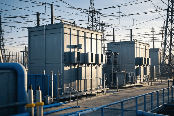
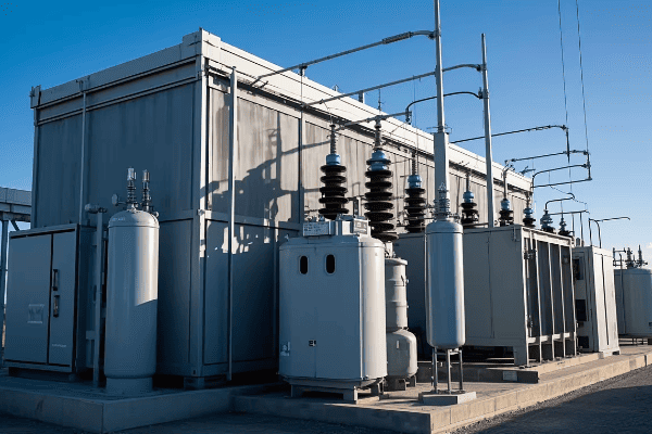
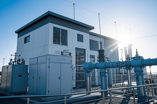
Have you ever wondered how cities manage to power skyscrapers and dense urban areas without massive electrical substations taking up valuable real estate? The answer lies in a revolutionary technology called Gas Insulated Substations (GIS).
A Gas Insulated Substation (GIS) is a compact power substation that uses sulfur hexafluoride (SF6) gas as an insulating medium. It revolutionizes power distribution by dramatically reducing the substation’s size, increasing reliability, and allowing installations in space-constrained urban areas or harsh environments.
As someone who’s worked in the power industry for years, I’ve seen firsthand how GIS technology has transformed urban power distribution. Let’s dive into the details of this innovative technology and explore why it’s becoming the go-to solution for modern power systems.
How Does a Gas Insulated Substation Work? Understanding the Basics
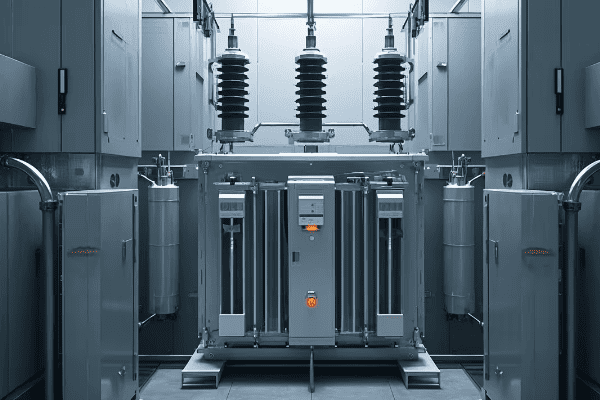
Imagine shrinking a football field-sized substation down to the size of a small house. That’s essentially what GIS technology does, and it’s all thanks to the unique properties of SF6 gas.
A Gas Insulated Substation works by enclosing high-voltage conductors and circuit breakers in sealed metal containers filled with SF6 gas. This gas has superior insulating properties compared to air, allowing components to be placed much closer together, resulting in a compact and efficient substation design.
Let’s break down the key aspects of how a GIS operates:
The Role of SF6 Gas
SF6 gas is the hero of GIS technology. Here’s why:
- Superior Insulation: SF6 has an insulation strength 2.5 to 3 times higher than air.
- Arc Quenching: It’s excellent at extinguishing electrical arcs, enhancing safety.
- Chemical Stability: SF6 doesn’t react with other materials in the substation.
- Heat Dissipation: It efficiently conducts heat away from conductors.
Sealed Environment
The sealed metal enclosures in a GIS offer several benefits:
- Protection from Environment: Dust, moisture, and pollutants can’t affect the equipment.
- Reduced Maintenance: The clean, controlled environment means less wear and tear.
- Enhanced Safety: The risk of external interference or accidents is minimized.
Compact Design
The compact nature of GIS is its most revolutionary aspect:
- Space Saving: A GIS can be up to 90% smaller than an equivalent Air Insulated Substation (AIS).
- Flexible Installation: GIS can be installed indoors, underground, or in tight urban spaces.
- Modular Construction: Easy to expand or reconfigure as needs change.
Here’s a comparison table to illustrate the space-saving aspect:
| Voltage Level | AIS Footprint | GIS Footprint | Space Saving |
|---|---|---|---|
| 110 kV | 3000 m² | 300 m² | 90% |
| 220 kV | 8000 m² | 600 m² | 92.5% |
| 400 kV | 15000 m² | 1000 m² | 93.3% |
I remember a project where we needed to upgrade a substation in a densely populated urban area. The local authorities were concerned about the impact on the neighborhood. By choosing GIS technology, we were able to fit the entire substation in a building the size of a small warehouse. The compact design not only satisfied the authorities but also impressed the local community with its minimal visual impact.
When explaining GIS to newcomers in the industry, I often use the analogy of comparing it to the evolution of computers. Just as we’ve gone from room-sized mainframes to powerful smartphones, GIS has allowed us to shrink substations without compromising on power or functionality.
Understanding the basics of GIS operation is crucial for anyone involved in modern power distribution. As urban areas continue to grow and energy demands increase, the ability to install powerful substations in compact spaces will become even more valuable.
What Are the Key Components of a Gas Insulated Substation?
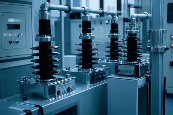
When I first encountered a Gas Insulated Substation, I was amazed by its compact design. But what’s inside this marvel of electrical engineering? Let’s unpack the key components that make GIS technology so effective.
A Gas Insulated Substation consists of several key components, all enclosed in SF6-filled compartments. These include circuit breakers, disconnectors, earthing switches, current and voltage transformers, and busbars. Each component is designed to operate efficiently in the SF6 environment, contributing to the overall compact and reliable nature of the GIS.
Let’s dive deeper into each of these components:
1. Circuit Breakers
Circuit breakers are the first line of defense in a GIS. They’re designed to:
- Interrupt fault currents quickly
- Operate in the SF6 environment for enhanced arc quenching
- Require minimal maintenance due to the clean, sealed environment
2. Disconnectors and Earthing Switches
These components provide isolation and grounding:
- Disconnectors isolate sections of the substation for maintenance
- Earthing switches ensure safety during maintenance operations
- Both are designed for reliable operation in the SF6 gas
3. Current and Voltage Transformers
These are crucial for measurement and protection:
- Current transformers measure electrical current
- Voltage transformers measure voltage levels
- Both are compact and designed specifically for GIS environments
4. Busbars
Busbars are the highways of electrical distribution in a GIS:
- They connect different sections of the substation
- SF6 insulation allows for compact busbar design
- They’re typically made of aluminum or copper
5. SF6 Gas System
This system is unique to GIS and includes:
- Gas monitoring equipment
- Pressure relief devices
- Gas handling and recycling systems
Here’s a table summarizing the key components and their functions:
| Component | Function | Unique GIS Feature |
|---|---|---|
| Circuit Breakers | Interrupt fault currents | Enhanced arc quenching in SF6 |
| Disconnectors | Isolate sections | Compact design in SF6 |
| Earthing Switches | Provide grounding | Safe operation in sealed environment |
| Current/Voltage Transformers | Measurement and protection | Designed for GIS environment |
| Busbars | Connect substation sections | Compact due to SF6 insulation |
| SF6 Gas System | Maintain insulation medium | Crucial for GIS operation |
I remember a project where we were upgrading an old air-insulated substation to a GIS. The client was skeptical about fitting all these components into such a small space. We arranged a visit to a GIS manufacturer, and seeing the compact, modular design of each component in person was a game-changer. The client was amazed at how each element was engineered to work seamlessly in the SF6 environment.
One aspect that often surprises people new to GIS technology is the modularity of these components. Unlike traditional substations where components are spread out, GIS components are designed to be interconnected modules. This not only saves space but also allows for easier installation and future upgrades.
When working with GIS, it’s crucial to understand how these components interact:
- The circuit breakers and disconnectors work together to provide both protection and isolation.
- The current and voltage transformers feed critical data to the protection and control systems.
- The SF6 gas system continuously monitors and maintains the insulating medium, ensuring the reliability of all other components.
This integrated design is what makes GIS so powerful. Each component is not just miniaturized but optimized for operation in the SF6 environment. The result is a substation that’s not only compact but also more reliable and efficient than its air-insulated counterpart.
Understanding these components is essential for anyone working with or specifying GIS technology. It’s not just about space-saving; it’s about creating a more efficient, reliable, and flexible power distribution system.
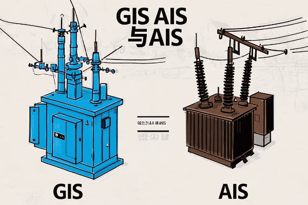
GIS vs AIS: What’s the Difference and Which One Should You Choose?
As someone who’s worked with both Gas Insulated Substations (GIS) and Air Insulated Substations (AIS), I’m often asked about their differences. It’s like comparing a smartphone to a landline – both make calls, but one offers significantly more in a smaller package.
The main difference between GIS and AIS lies in their insulating medium and size. GIS uses SF6 gas and is compact, while AIS uses air and requires more space. GIS is ideal for urban areas or where space is limited, while AIS is often more cost-effective for rural or spacious locations. The choice depends on factors like available space, environmental conditions, and budget.
Let’s dive deeper into the key differences and factors to consider when choosing between GIS and AIS:
Size and Space Requirements
-
GIS
- Typically 10-15% the size of an equivalent AIS
- Can be installed indoors, underground, or in tight spaces
- Ideal for urban areas or where land is expensive
-
AIS
- Requires large open areas
- Typically outdoor installations
- Suitable for rural areas or where land is readily available
Environmental Protection
-
GIS
- Enclosed design protects against environmental factors
- Can operate in harsh conditions (pollution, salt spray, etc.)
- Less affected by weather
-
AIS
- Exposed to environmental elements
- May require additional protection in harsh environments
- Performance can be affected by weather conditions
Maintenance Requirements
-
GIS
- Lower maintenance due to sealed environment
- Less frequent inspections needed
- Specialized skills required for SF6 handling
-
AIS
- Regular cleaning and inspection required
- More susceptible to environmental wear and tear
- Maintenance is generally simpler and doesn’t require specialized gas handling skills
Initial Cost vs. Long-term Cost
-
GIS
- Higher initial investment
- Lower long-term maintenance costs
- Potential savings in land costs in urban areas
-
AIS
- Lower initial cost
- Higher long-term maintenance costs
- May require significant land investment in urban areas
Here’s a comparison table to help visualize the differences:
| Factor | GIS | AIS |
|---|---|---|
| Space Requirement | Low | High |
| Environmental Protection | High | Low |
| Maintenance Frequency | Low | High |
| Initial Cost | High | Low |
| Long-term Cost | Lower | Higher |
| Flexibility in Location | High | Limited |
| Specialized Skills for Maintenance | Required | Not Required |
I recall a project where we were debating between GIS and AIS for a new substation in a growing suburban area. Initially, the client leaned towards AIS due to lower upfront costs. However, when we factored in the rapidly increasing land values and the area’s growth projections, GIS became the clear winner. The compact GIS design allowed for future expansion without additional land purchases, proving to be more cost-effective in the long run.
When choosing between GIS and AIS, consider these factors:
- Available Space: If space is limited, GIS is often the only viable option.
- Environmental Conditions: For harsh environments, GIS offers better protection.
- Future Expansion Plans: GIS offers more flexibility for future upgrades in tight spaces.
- Budget Constraints: Consider both initial and long-term costs.
- Maintenance Capabilities: Ensure you have access to necessary maintenance skills, especially for GIS.
In my experience, the trend is moving towards GIS, especially in urban and suburban areas. However, AIS still has its place, particularly in rural areas or where land is abundant and cheap.
Remember, the choice between GIS and AIS isn’t always black and white. In some cases, a hybrid approach using both technologies in different parts of the substation can provide the best of both worlds. Always consider your specific needs and constraints when making this important decision.
What Are the Advantages and Challenges of Using Gas Insulated Substations?
In my years working with power distribution systems, I’ve seen Gas Insulated Substations (GIS) transform the way we think about electrical infrastructure. But like any technology, GIS comes with its own set of pros and cons.
Gas Insulated Substations offer significant advantages in terms of space-saving, reliability, and environmental protection. However, they also present challenges such as higher initial costs, specialized maintenance requirements, and environmental concerns related to SF6 gas. Understanding these factors is crucial for making informed decisions about substation design and implementation.

Let’s dive deeper into the advantages and challenges of GIS:
Advantages of Gas Insulated Substations
-
Compact Design
- GIS can be up to 90% smaller than equivalent AIS
- Allows for installation in urban areas or indoor locations
- Reduces land acquisition costs
-
Increased Reliability
- Sealed environment protects against environmental factors
- Less exposure to pollution, humidity, and wildlife
- Reduced maintenance needs
-
Enhanced Safety
- Enclosed design minimizes risk of electrical accidents
- Reduced electromagnetic field emissions
- Fire risks are significantly lower
-
Flexibility in Installation
- Can be installed underground, in buildings, or on rooftops
- Modular design allows for easy expansion
- Suitable for harsh environments (coastal areas, industrial zones)
-
Long Lifespan
- Protected components last longer
- Typical lifespan of 40-50 years, compared to 30-40 for AIS
Challenges of Gas Insulated Substations
-
Higher Initial Costs
- GIS equipment is more expensive than AIS
- Specialized installation procedures increase costs
-
Specialized Maintenance
- Requires technicians trained in SF6 handling
- Special equipment needed for gas handling and testing
-
Environmental Concerns
- SF6 is a potent greenhouse gas
- Strict regulations on SF6 handling and disposal
- Potential for fines if gas leaks occur
-
Limited Accessibility
- Enclosed design can make some components hard to access
- Major repairs may require extensive disassembly
-
Technology Lock-in
- Once installed, switching to a different system is costly
- Future upgrades may be limited by the initial design
Here’s a table summarizing the advantages and challenges:
| Aspect | Advantages | Challenges |
|---|---|---|
| Space | Compact design | Limited accessibility |
| Reliability | High due to sealed environment | Specialized maintenance required |
| Safety | Enhanced personnel safety | Environmental risk from SF6 |
| Flexibility | Versatile installation options | Technology lock-in |
| Cost | Lower long-term costs | Higher initial investment |
| Lifespan | Longer than AIS | Disposal of SF6 at end-of-life |
I remember a project where we installed a GIS in a coastal area prone to salt spray and high humidity. The client was initially concerned about the higher upfront cost. However, after five years of operation, the reduced maintenance needs and consistent performance in the harsh environment more than justified the initial investment. The AIS in the same region required frequent cleaning and component replacements due to corrosion.
When considering GIS, it’s crucial to weigh these factors:
- Long-term Planning: Consider future expansion needs and potential technology advancements.
- Environmental Regulations: Stay informed about SF6 regulations in your area.
- Maintenance Capabilities: Ensure you have access to skilled technicians for GIS maintenance.
- Life Cycle Costs: Look beyond initial costs to total ownership costs over the substation’s lifespan.
- Site-Specific Factors: Consider local environmental conditions, space constraints, and reliability requirements.
In my experience, the advantages of GIS often outweigh the challenges, especially in urban or environmentally challenging locations. However, it’s not a one-size-fits-all solution. Each project requires careful consideration of these factors to determine if GIS is the right choice.
As the technology evolves, we’re seeing innovations that address some of these challenges. For example, some manufacturers are developing GIS designs that use alternative gases with lower environmental impact. It’s an exciting time in the industry, and I’m looking forward to seeing how these developments shape the future of power distribution.
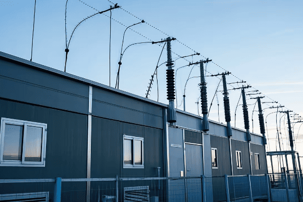
How Do Gas Insulated Substations Impact Urban Power Distribution?
As cities grow taller and denser, the challenge of powering them efficiently becomes more complex. This is where Gas Insulated Substations (GIS) come into play, revolutionizing urban power distribution in ways that were unimaginablejust a few decades ago.
Gas Insulated Substations have a significant impact on urban power distribution by allowing high-voltage substations to be installed in compact spaces within cities. This enables power to be distributed more efficiently, closer to load centers, reducing transmission losses and improving reliability. GIS technology facilitates urban development without compromising on electrical infrastructure.
Let’s explore the various ways GIS impacts urban power distribution:
1. Space Optimization in Dense Urban Areas
In cities where every square foot counts, GIS offers a game-changing solution:
- Compact Footprint: A GIS can be up to 90% smaller than an equivalent AIS.
- Vertical Integration: GIS can be installed in multi-story buildings or underground.
- Repurposing of Space: Areas above or around GIS can be used for other purposes.
I once worked on a project in a major city where we installed a GIS on the ground floor of a new office building. The compact design allowed the developer to use the rest of the building for commercial space, effectively hiding the substation in plain sight.
2. Improved Power Quality and Reliability
GIS technology enhances the reliability of urban power distribution:
- Reduced Outages: Protected from environmental factors, GIS experiences fewer failures.
- Faster Restoration: Modular design allows for quicker repairs when issues do occur.
- Stable Voltage Profiles: Closer proximity to load centers helps maintain consistent voltage levels.
3. Aesthetic and Environmental Considerations
GIS helps cities maintain their aesthetic appeal and environmental standards:
- Visual Impact: Can be housed in buildings that blend with urban architecture.
- Noise Reduction: Enclosed design significantly reduces operational noise.
- EMF Mitigation: Metal enclosures contain electromagnetic fields, addressing public health concerns.
4. Facilitating Smart Grid Integration
GIS plays a crucial role in modernizing urban power grids:
- Digital Integration: Easy to incorporate advanced monitoring and control systems.
- Flexibility: Can accommodate changes in power flow directions, essential for renewable energy integration.
- Future-Proofing: Modular design allows for easier upgrades as technology advances.
Here’s a table comparing urban power distribution before and after GIS implementation:
| Aspect | Before GIS | After GIS |
|---|---|---|
| Substation Location | Outskirts of cities | Within city centers |
| Power Transmission Losses | Higher due to long distances | Reduced due to proximity to load |
| Land Use in Cities | Large areas dedicated to substations | Minimal land use, integration with buildings |
| Reliability | Vulnerable to environmental factors | Enhanced due to protected equipment |
| Aesthetic Impact | Visible, often unsightly | Can be hidden or integrated into architecture |
| Smart Grid Readiness | Limited | High, with easy integration of digital technologies |
I recall a project in a historic European city where installing a traditional substation would have been impossible due to space constraints and preservation laws. By using GIS technology, we were able to fit a high-capacity substation in the basement of a centuries-old building. This not only preserved the city’s character but also significantly improved power reliability in the old town area.
The impact of GIS on urban power distribution extends beyond just technical benefits:
- Economic Growth: Reliable power infrastructure attracts businesses and supports economic development.
- Urban Planning Flexibility: Planners have more options when they’re not constrained by large substation footprints.
- Sustainability: By reducing transmission losses and facilitating renewable energy integration, GIS supports cities’ sustainability goals.
- Public Safety: Enclosed GIS designs enhance safety in densely populated areas.
As cities continue to grow and evolve, the role of GIS in urban power distribution will only become more critical. The ability to provide reliable, high-capacity power in compact spaces is essential for supporting smart cities, electric vehicle charging infrastructure, and the increasing power demands of modern urban life.
What is the Environmental Impact of SF6 Gas in GIS Technology?
As someone deeply involved in the power industry, I’ve seen the tremendous benefits of Gas Insulated Substation (GIS) technology. However, it’s crucial to address the elephant in the room – the environmental impact of sulfur hexafluoride (SF6) gas used in these systems.
SF6 gas, while excellent for electrical insulation, is a potent greenhouse gas with a global warming potential 23,500 times that of CO2. Its use in GIS technology presents environmental challenges, including potential leaks and end-of-life disposal issues. However, proper management and emerging alternatives are helping to mitigate these concerns.
Let’s delve deeper into the environmental aspects of SF6 in GIS:
1. Global Warming Potential
SF6 is the most potent greenhouse gas known:
- High GWP: Global Warming Potential of 23,500 over 100 years.
- Long Atmospheric Lifetime: SF6 can persist in the atmosphere for up to 3,200 years.
- Cumulative Effect: Even small leaks can have a significant long-term impact.
2. Leakage Concerns
While GIS systems are designed to be sealed, leaks can occur:
- Annual Leakage Rate: Typically less than 0.1% per year, but can vary.
- Monitoring: Regular checks are essential to detect and prevent leaks.
- Repair Challenges: Fixing leaks in a live GIS can be complex and costly.
3. End-of-Life Disposal
Proper disposal of SF6 at the end of a GIS’s life is crucial:
- Recycling: SF6 can be reclaimed and purified for reuse.
- Destruction: Technologies exist to destroy SF6, but they’re energy-intensive.
- Regulatory Compliance: Strict regulations govern SF6 disposal in many countries.
4. Mitigation Strategies
The industry is actively working to reduce the environmental impact of SF6:
- Improved Sealing: Advanced designs minimize leakage potential.
- Better Monitoring: New technologies allow for more accurate leak detection.
- Alternative Gases: Research into less harmful insulating gases is ongoing.
Here’s a table summarizing the environmental aspects of SF6 use in GIS:
| Aspect | Impact | Mitigation Strategies |
|---|---|---|
| Global Warming Potential | Very High (23,500 times CO2) | Use of alternative gases, improved containment |
| Atmospheric Lifetime | 3,200 years | Proper disposal and recycling |
| Annual Leakage Rate | Typically <0.1% | Enhanced sealing, regular monitoring |
| End-of-Life Management | Challenging | Recycling, destruction technologies |
| Regulatory Compliance | Strict in many countries | Training, documentation, proper handling procedures |
I remember a project where we were upgrading an old GIS installation. The client was concerned about the environmental impact of the existing SF6. We implemented a comprehensive SF6 management plan, including advanced leak detection systems and a recycling program for the old gas. This not only addressed the environmental concerns but also improved the overall efficiency of the substation.
When dealing with SF6 in GIS, consider these key points:
- Lifecycle Management: Plan for proper handling from installation to decommissioning.
- Regular Monitoring: Implement robust leak detection and monitoring systems.
- Staff Training: Ensure all personnel are trained in proper SF6 handling procedures.
- Alternative Technologies: Stay informed about emerging alternatives to SF6.
- Regulatory Compliance: Keep up-to-date with and adhere to local and international regulations.
The industry is actively working on solutions to reduce the environmental impact of SF6:
- Gas Mixtures: Some manufacturers are developing GIS that use a mixture of SF6 and other gases, reducing the overall SF6 content.
- Alternative Gases: Research is ongoing into gases like fluoronitriles and fluoroketones that have much lower global warming potential.
- Vacuum Technology: For certain applications, vacuum interrupters are being used as an SF6-free alternative.
While the environmental impact of SF6 is a significant concern, it’s important to balance this against the benefits of GIS technology. The compact nature of GIS allows for more efficient power distribution in urban areas, potentially reducing overall energy consumption and associated emissions. Additionally, the reliability of GIS can lead to fewer outages and less energy waste.
As we move towards a more sustainable future, the power industry must continue to innovate and find ways to minimize the environmental impact of essential technologies like GIS. It’s an exciting time in the field, and I’m optimistic about the progress we’re making in developing more environmentally friendly solutions.
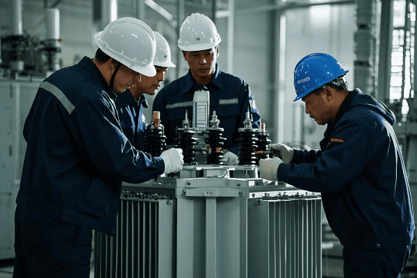
How Are Gas Insulated Substations Maintained and What Safety Measures Are Required?
Maintaining a Gas Insulated Substation (GIS) is like performing a delicate ballet – it requires precision, expertise, and a keen awareness of safety. As someone who’s overseen numerous GIS maintenance operations, I can tell you that proper maintenance is crucial for the longevity and reliability of these systems.
Gas Insulated Substations require specialized maintenance procedures focusing on SF6 gas management, component inspection, and electrical testing. Safety measures are critical due to high voltage and the presence of SF6 gas. Key safety requirements include proper personal protective equipment (PPE), SF6 handling protocols, and strict adherence to lockout/tagout procedures.
Let’s break down the maintenance procedures and safety measures:
Maintenance Procedures
-
SF6 Gas Management
- Regular gas quality checks
- Leak detection and repair
- Gas pressure monitoring and top-up if necessary
-
Visual Inspections
- Check for signs of corrosion or damage
- Inspect seals and gaskets
- Verify proper operation of indicators and gauges
-
Electrical Testing
- Partial discharge measurements
- Contact resistance tests
- Insulation resistance tests
-
Mechanical Checks
- Verify proper operation of switches and circuit breakers
- Check alignment of components
- Lubricate moving parts as needed
-
Control and Protection Systems
- Test relay functions
- Calibrate measuring instruments
- Update software if required
Safety Measures
-
Personal Protective Equipment (PPE)
- Insulated gloves and boots
- Arc-flash protective clothing
- Respiratory protection when handling SF6
-
SF6 Handling Protocols
- Use specialized SF6 handling equipment
- Follow proper procedures for gas recovery and recycling
- Ensure adequate ventilation in work areas
-
Lockout/Tagout Procedures
- Implement strict procedures for de-energizing equipment
- Use personal locks and tags to prevent accidental energization
- Verify absence of voltage before work begins
-
Training and Certification
- Ensure all personnel are properly trained in GIS maintenance
- Require certification for SF6 handling
- Conduct regular safety refresher courses
-
Emergency Procedures
- Develop and practice emergency response plans
- Install SF6 gas detectors in GIS rooms
- Provide first aid training specific to electrical and SF6 exposure incidents
Here’s a maintenance and safety checklist table:
| Maintenance Task | Frequency | Safety Measures |
|---|---|---|
| SF6 Quality Check | Annual | PPE, Ventilation |
| Visual Inspection | Monthly | PPE, Lockout/Tagout |
| Electrical Testing | 2-3 Years | PPE, Lockout/Tagout, Training |
| Mechanical Checks | Annual | PPE, Lockout/Tagout |
| Control System Test | 6 Months | Training, Software Security |
| Leak Detection | Continuous | Gas Detectors, Ventilation |
I recall a maintenance operation where we discovered a small SF6 leak during a routine inspection. Thanks to our rigorous safety protocols and well-trained team, we were able to safely isolate the affected compartment, repair the leak, and recharge the system without any safety incidents or significant downtime. This experience reinforced the importance of regular maintenance and strict adherence to safety procedures.
Key considerations for GIS maintenance and safety:
- Predictive Maintenance: Implement condition monitoring systems to predict potential issues before they become critical.
- Documentation: Maintain detailed records of all maintenance activities and gas handling.
- Specialized Tools: Invest in proper tools and equipment designed for GIS maintenance.
- Environmental Compliance: Ensure all maintenance activities comply with environmental regulations regarding SF6 handling.
- Risk Assessment: Conduct thorough risk assessments before any maintenance activity.
Maintaining a GIS requires a different mindset compared to traditional air-insulated substations. The enclosed nature of GIS means that many components are not visible for easy inspection. This makes diagnostic tools and preventive maintenance even more critical.
One aspect that often surprises newcomers to GIS maintenance is the importance of cleanliness. Even tiny particles can compromise the insulating properties of SF6, so maintaining a clean environment during maintenance is crucial.
As technology evolves, we’re seeing new tools that make GIS maintenance safer and more efficient. For example, robotic inspection systems can now perform visual inspections in energized GIS compartments, reducing the need for shutdowns and human exposure to high-voltage environments.
Remember, while GIS technology offers many advantages in terms of reliability and compact design, it requires a specialized approach to maintenance and safety. By following proper procedures and investing in training and equipment, we can ensure that GIS continues to play a crucial role in our power distribution systems for years to come.
Conclusion
Gas Insulated Substations represent a significant advancement in power distribution technology, offering compact, reliable, and efficient solutions for modern electrical needs. While they present challenges, particularly in environmental impact and specialized maintenance, their benefits in urban settings and harsh environments are undeniable. As the technology evolves, GIS will continue to play a crucial role in shaping our electrical infrastructure.
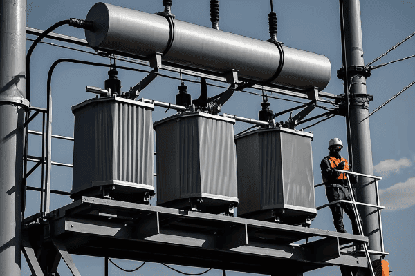
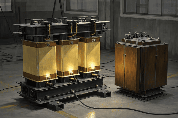
Have you ever wondered how large buildings manage their power distribution in tight spaces? The answer might lie in a clever piece of technology called the triplex core transformer.
A triplex core transformer is a specialized electrical device that consists of three single-phase transformers in one unit. It’s used in building installations because it can be easily disassembled and reassembled, making it ideal for tight spaces or buildings with limited access.
As someone who’s worked in the power distribution industry for years, I’ve seen firsthand how triplex core transformers can solve complex installation challenges. Let’s dive into the details of this innovative technology and explore why it’s becoming increasingly popular in modern building designs.
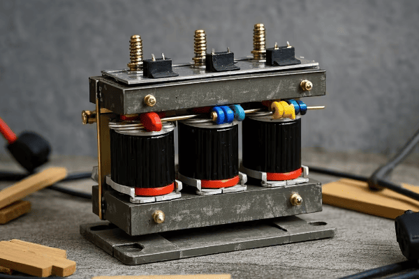
How Does a Triplex Core Transformer Differ from Traditional Transformers?
Imagine trying to fit a large, bulky piece of furniture through a narrow doorway. That’s often the challenge with traditional transformers in building installations. Triplex core transformers offer a solution to this common problem.
Triplex core transformers differ from traditional transformers in their modular design. They consist of three separate single-phase units that can be easily disassembled. Traditional transformers, on the other hand, are typically one large, integrated unit. This key difference allows for much greater flexibility in installation and maintenance.
Let’s break down the key differences:
Design and Structure
-
Triplex Core Transformer
- Three separate single-phase units
- Modular design for easy disassembly
- Compact when assembled
-
Traditional Transformer
- Single integrated unit
- Fixed design
- Often bulkier overall
Installation Flexibility
Triplex core transformers offer significant advantages when it comes to installation. I remember a project where we needed to upgrade the power distribution in an old office building. The service elevator was too small for a traditional transformer, but we easily transported a triplex core transformer piece by piece and assembled it on-site.
Maintenance and Repairs
Another major difference lies in maintenance. With a triplex core transformer, you can often service or replace one phase without shutting down the entire system. This can be a huge advantage in critical applications where downtime is costly.
Here’s a comparison table to illustrate the differences:
| Feature | Triplex Core Transformer | Traditional Transformer |
|---|---|---|
| Design | Modular (3 single-phase units) | Integrated single unit |
| Installation | Easy in tight spaces | Can be challenging in confined areas |
| Maintenance | Can service individual phases | Typically requires full shutdown |
| Size | Compact when assembled | Often larger overall |
| Flexibility | High | Low |
In my experience, the choice between a triplex core and a traditional transformer often comes down to the specific requirements of the installation site. While traditional transformers are still widely used and have their advantages, triplex core transformers are becoming increasingly popular in urban environments where space is at a premium.
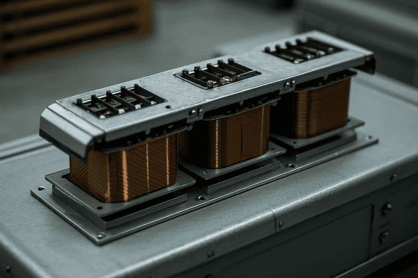
What Are the Key Components of a Triplex Core Transformer?
When I first encountered a triplex core transformer, I was amazed by its ingenious design. Understanding its components is crucial for anyone involved in power distribution or building management.
A triplex core transformer consists of three main components: the core, the windings, and the enclosure. Each of the three single-phase units has its own core and windings, all housed within a common enclosure. This design allows for modularity while maintaining the functionality of a three-phase transformer.
Let’s dive deeper into each component:
1. The Core
The core is the heart of each single-phase unit in a triplex core transformer. Here’s what you need to know:
- Material: Typically made of high-grade silicon steel
- Design: Usually a shell-type or core-type design
- Function: Provides a path for magnetic flux, crucial for the transformation process
2. The Windings
Each single-phase unit has its own set of windings. These are key to the transformer’s operation:
- Primary Winding: Connects to the input voltage
- Secondary Winding: Delivers the output voltage
- Material: Usually copper or aluminum
- Insulation: High-quality materials to prevent short circuits
3. The Enclosure
The enclosure is what sets triplex core transformers apart. It houses all three single-phase units:
- Design: Modular for easy disassembly
- Material: Usually steel, with proper ventilation
- Features: Often includes cooling systems and monitoring equipment
Here’s a table summarizing the components:
| Component | Function | Key Features |
|---|---|---|
| Core | Magnetic flux path | High-grade silicon steel, efficient design |
| Windings | Voltage transformation | Copper/aluminum, well-insulated |
| Enclosure | Houses components | Modular, steel construction, cooling system |
In my years of working with transformers, I’ve found that the modular nature of triplex core transformers offers unique advantages. For instance, I once worked on a project where we needed to replace a faulty winding. With a traditional transformer, this would have meant replacing the entire unit. But with the triplex core design, we were able to replace just the affected single-phase unit, saving time and money.
Understanding these components is crucial for anyone working with or specifying triplex core transformers. The modular design not only aids in installation but also in maintenance and repairs, making these transformers a versatile choice for many building installations.
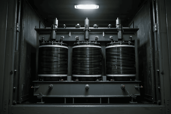
Why Are Triplex Core Transformers Ideal for Tight Installation Spaces?
Have you ever tried to squeeze a large appliance through a narrow doorway? That’s often the challenge with installing traditional transformers in existing buildings. This is where triplex core transformers shine.
Triplex core transformers are ideal for tight installation spaces because of their modular design. They can be disassembled into smaller, more manageable parts, making it easier to transport through narrow corridors, small elevators, or tight spaces. Once at the installation site, they can be reassembled quickly.
Let’s explore why this design is so advantageous in confined spaces:
1. Easy Transportation
The modular nature of triplex core transformers makes them much easier to transport. I remember a project in an old downtown building where the service elevator was too small for a traditional transformer. We easily moved the triplex core transformer piece by piece and assembled it on-site.
2. Flexible Installation
Triplex core transformers offer more flexibility in terms of layout. You can arrange the three single-phase units in various configurations to fit the available space. This is particularly useful in buildings with irregular-shaped utility rooms.
3. Reduced Need for Large Access Points
With traditional transformers, you often need to create large access points or even remove walls to get the equipment in place. Triplex core transformers can usually be brought in through standard doorways, reducing installation costs and structural modifications.
4. Easier Future Replacements or Upgrades
If you need to replace or upgrade the transformer in the future, the modular design of triplex core transformers makes this process much simpler. You don’t need to worry about how you’ll remove a large, integrated unit.
Here’s a comparison table of installation considerations:
| Factor | Triplex Core Transformer | Traditional Transformer |
|---|---|---|
| Transportation | Easy, can be moved in parts | Challenging, requires large access |
| Layout Flexibility | High, can be arranged to fit space | Low, fixed configuration |
| Access Requirements | Standard doorways often sufficient | May require wall removal or large openings |
| Future Replacement | Simplified, can replace parts | Complex, may require complete unit removal |
In my experience, the advantages of triplex core transformers in tight spaces go beyond just the initial installation. I once worked on a project where we needed to upgrade the power capacity of an old office building. The existing utility room was cramped, with no easy way to remove the old transformer or bring in a new, larger one. By switching to a triplex core design, we were able to increase capacity without major construction work.
The ability to work within existing spatial constraints is becoming increasingly important as cities grow denser and buildings are repurposed. Triplex core transformers offer a solution that can adapt to these challenges, making them an excellent choice for urban environments and retrofit projects.
How Do You Install and Maintain a Triplex Core Transformer?
Installing and maintaining a triplex core transformer might seem daunting at first, but with the right approach, it can be more straightforward than you might think. Let me walk you through the process based on my years of experience in the field.
Installing a triplex core transformer involves transporting the disassembled units, reassembling them on-site, and connecting them to the power system. Maintenance includes regular inspections, oil testing (for oil-filled units), and occasional part replacements. The modular design allows for easier maintenance compared to traditional transformers.
Let’s break down the installation and maintenance process:
Installation Process
-
Site Preparation
- Ensure the installation area meets size and weight requirements
- Prepare a proper foundation or mounting surface
-
Transportation
- Move the disassembled units to the installation site
- This is often easier than moving a single large transformer
-
Assembly
- Carefully reassemble the three single-phase units
- Follow manufacturer guidelines for proper alignment
-
Connection
- Connect the primary and secondary windings
- Install any necessary cooling systems or monitoring equipment
-
Testing
- Conduct thorough testing before energizing the transformer
Maintenance Procedures
-
Regular Inspections
- Visual checks for any signs of damage or wear
- Listen for unusual noises during operation
-
Oil Testing (for oil-filled units)
- Regular oil sampling and analysis
- Top up or replace oil as needed
-
Thermal Imaging
- Use infrared cameras to detect hot spots
-
Part Replacement
- Replace individual components as needed, without necessarily replacing the entire transformer
Here’s a maintenance schedule table based on my experience:
| Maintenance Task | Frequency | Importance |
|---|---|---|
| Visual Inspection | Monthly | High |
| Oil Testing | Annually | Critical |
| Thermal Imaging | Bi-annually | Medium |
| Winding Resistance Test | Every 3-5 years | High |
| Insulation Resistance Test | Annually | Critical |
I remember a case where we installed a triplex core transformer in a renovated historical building. The narrow staircases and small elevator would have made it impossible to bring in a traditional transformer. We easily transported the triplex core units separately and assembled them in the basement. The modular design not only solved our installation challenge but also made future maintenance much easier.
One key advantage I’ve found with triplex core transformers is the ability to perform maintenance on one phase without necessarily shutting down the entire system. This can be crucial in applications where continuous power supply is critical.
When it comes to maintenance, always follow these best practices:
- Adhere to manufacturer guidelines and local regulations
- Keep detailed maintenance records
- Train personnel in proper handling and safety procedures
- Plan for regular maintenance to prevent unexpected failures
Remember, while the modular design of triplex core transformers can simplify many aspects of installation and maintenance, it’s still crucial to have qualified professionals handle these tasks. Proper installation and maintenance not only ensure optimal performance but also extend the life of your transformer.
What Are the Efficiency and Cost Considerations of Triplex Core Transformers?
When it comes to choosing a transformer, efficiency and cost are always top concerns. As someone who’s worked with various transformer types, I can tell you that triplex core transformers have some unique considerations in these areas.
Triplex core transformers often have slightly lower efficiency than traditional three-phase transformers due to their modular design. However, they can be more cost-effective in certain scenarios, especially when considering installation costs in tight spaces. The total cost of ownership, including maintenance and potential replacement, can be lower for triplex core transformers.
Let’s dive deeper into the efficiency and cost aspects:
Efficiency Considerations
-
Core Losses
- Triplex core transformers may have slightly higher core losses due to the three separate cores
- Modern designs are continually improving efficiency
-
Load Losses
- Generally comparable to traditional transformers
- Can be optimized for specific load profiles
-
Overall Efficiency
- Typically 1-2% lower than equivalent traditional three-phase transformers
- This gap is narrowing with advancements in materials and design
Cost Considerations
-
Initial Purchase Cost
- Often higher than traditional transformers of the same rating
- Price difference is decreasing as triplex core transformers become more common
-
Installation Costs
- Can be significantly lower, especially in tight spaces or existing buildings
- Reduced need for large access points or structural modifications
-
Maintenance Costs
- Potentially lower due to the ability to service or replace individual phases
- Easier access can reduce labor costs for maintenance
-
Replacement Costs
- Lower in the long term, as you can replace individual units rather than the entire transformer
Here’s a comparison table of efficiency and cost factors:
| Factor | Triplex Core Transformer | Traditional Transformer |
|---|---|---|
| Core Losses | Slightly higher | Lower |
| Load Losses | Comparable | Comparable |
| Overall Efficiency | 97-98% | 98-99% |
| Initial Cost | Higher | Lower |
| Installation Cost | Lower in tight spaces | Higher in tight spaces |
| Maintenance Cost | Potentially lower | Potentially higher |
| Replacement Cost | Lower (modular) | Higher (entire unit) |
I remember a project where we were upgrading the electrical system in an old hospital. The initial cost of the triplex core transformer was about 15% higher than a traditional unit. However, when we factored in the reduced installation costs (no need to remove walls) and the potential for easier future maintenance, the total cost of ownership over 20 years was actually lower for the triplex core option.
When considering efficiency and cost, keep these points in mind:
- Look at the total cost of ownership, not just the initial purchase price
- Consider the specific installation environment and how it might affect costs
- Factor in potential savings from easier maintenance and partial replacements
- Evaluate the impact of slightly lower efficiency against other benefits
In my experience, while triplex core transformers might not always be the most efficient option on paper, their practical advantages often make them a cost-effective choice, especially in challenging installation environments. As with any major equipment decision, it’s crucial to analyze your specific needs and constraints to determine the best option for your situation.
In Which Scenarios Should You Choose a Triplex Core Transformer Over Other Types?
Choosing the right transformer for your project can be a complex decision. As someone who’s been in the field for years, I’ve seen triplex core transformers shine in certain scenarios while traditional transformers were better in others.
Triplex core transformers are ideal for installations in tight spaces, buildings with limited access, and situations where future flexibility is crucial. They’re particularly well-suited for urban environments, retrofits of older buildings, and applications where minimizing downtime during maintenance is critical.
Let’s explore the scenarios where triplex core transformers are the best choice:
1. Limited Space Installations
If you’re working with a cramped utility room or a tight basement, triplex core transformers are often the go-to solution. Their modular design allows for easier transportation and installation in confined spaces.
2. Buildings with Restricted Access
For installations in high-rise buildings, historical structures, or any location with narrow corridors or small elevators, the ability to transport the transformer in parts is a huge advantage.
3. Retrofit Projects
When upgrading electrical systems in existing buildings, triplex core transformers can often be installed without major structural modifications, saving time and money.
4. Applications Requiring High Reliability
In scenarios where minimizing downtime is crucial (like hospitals or data centers), the ability to service or replace one phase without shutting down the entire system can be invaluable.
5. Future-Proofing Installations
If you anticipate the need for future capacity upgrades or potential relocation of the transformer, the modular nature of triplex core units offers greater flexibility.
Here’s a decision matrix to help guide your choice:
| Scenario | Triplex Core Transformer | Traditional Transformer | |
|---|---|---|---|
| Tight Installation Space | Ideal | Challenging | |
| Easy Access for Installation | Suitable | Preferred | |
| Critical Uptime Requirements | Excellent | Good | |
| Initial Cost Sensitivity | Less Suitable | More Suitable | |
| Future Flexibility Needs | Excellent | Limited | I recall a project where we were upgrading the electrical system in a busy downtown hotel. The existing transformer room was in the basement, accessible only through a narrow staircase. A traditional transformer would have required extensive and disruptive construction work. We opted for a triplex core transformer, which we easily transported down the stairs in pieces and assembled on-site. This choice minimized disruption to the hotel’s operations and saved significant costs in construction. |
When deciding between a triplex core and a traditional transformer, consider these factors:
-
Installation Environment
- Assess the available space and access routes
- Consider any weight restrictions on floors or elevators
-
Long-term Maintenance Plans
- Evaluate the importance of minimizing downtime during maintenance
- Consider the availability of skilled technicians for each type
-
Future Expansion Plans
- Think about potential needs for increased capacity
- Consider the likelihood of needing to relocate the transformer
-
Budget Constraints
- Look at both initial costs and long-term total cost of ownership
- Factor in potential savings from easier installation and maintenance
-
Efficiency Requirements
- Assess the impact of slightly lower efficiency in triplex core designs
- Consider local energy costs and regulations
Here’s a quick checklist to help you decide:
- [ ] Is the installation space tight or hard to access?
- [ ] Is minimizing future maintenance downtime crucial?
- [ ] Do you anticipate needing to upgrade or move the transformer in the future?
- [ ] Can you accommodate a slightly higher initial cost for long-term benefits?
- [ ] Are the efficiency differences within acceptable limits for your application?
If you answered yes to most of these questions, a triplex core transformer might be the best choice for your project.
In my experience, triplex core transformers have been game-changers in urban environments and retrofit projects. However, they’re not always the best choice. For new constructions with ample space and straightforward access, traditional transformers often remain the more cost-effective option.
Remember, every project is unique. It’s always worth consulting with experienced professionals and possibly conducting a site survey before making your final decision. The right choice will depend on a careful balance of your specific needs, constraints, and long-term goals.
Conclusion
Triplex core transformers offer unique advantages in tight spaces and challenging installations. While they may have slightly lower efficiency and higher initial costs, their flexibility in installation, maintenance, and future upgrades often makes them the ideal choice for many modern building projects.
Have you ever wondered why your power flickers when a large electrical system starts up? The answer might lie in a phenomenon called transformer surge current.
Transformer surge current is a temporary, high-magnitude current that occurs when a transformer is energized. It can be 6-8 times the rated current, potentially causing power quality issues and equipment stress. Understanding and managing surge current is crucial for maintaining reliable power systems.

As someone who’s spent years working with power systems, I’ve seen firsthand the impact of surge currents. Let’s dive into this fascinating aspect of transformer operation and explore why it matters for everyone in the electrical industry.
What Exactly is Transformer Surge Current and Why Does it Matter?
Imagine turning on a massive engine. The initial roar is much louder than its normal running sound. That’s similar to what happens with transformer surge current.
Transformer surge current, also called inrush current, is a large, temporary current that flows when a transformer is first energized. It typically lasts for a few cycles to several seconds and can be 6-8 times the transformer’s rated current. This matters because it can cause power fluctuations, trigger protective devices, and potentially damage equipment.
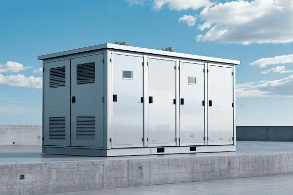
Let’s break down the key aspects of transformer surge current:
Understanding the Surge
-
Cause of the Surge
- Sudden magnetization of the transformer core
- Residual magnetism in the core
- Voltage phase angle at the moment of energization
-
Duration
- Typically lasts for a few cycles to several seconds
- Decays exponentially over time
-
Magnitude
- Can reach 6-8 times the rated current
- Varies based on transformer size and design
-
Frequency Components
- Contains both AC and DC components
- Rich in harmonics, especially second and third
Here’s a table summarizing the characteristics of surge current:
| Characteristic | Normal Current | Surge Current |
|---|---|---|
| Magnitude | 1x rated | 6-8x rated |
| Duration | Continuous | Few cycles to seconds |
| Waveform | Sinusoidal | Distorted, with harmonics |
| DC Component | None | Significant |
I remember a case where a large industrial client was experiencing frequent circuit breaker trips during transformer energization. We discovered that the surge current was exceeding the breaker’s instantaneous trip setting. By adjusting the protection settings and implementing controlled switching, we resolved the issue, saving the client significant downtime and frustration.
Understanding surge current is crucial for:
- Proper transformer design
- Accurate protection system settings
- Preventing unnecessary outages
- Ensuring power quality for sensitive loads
In my experience, many electrical engineers underestimate the impact of surge current. It’s not just a theoretical concept – it has real-world implications for system reliability and equipment longevity.
How Does Core Saturation Contribute to Surge Current in Transformers?
Picture a sponge that’s already wet trying to absorb more water. It can’t take much more, right? That’s similar to what happens with core saturation in transformers.
Core saturation occurs when the magnetic flux in a transformer’s core exceeds its capacity. This leads to a dramatic increase in magnetizing current, contributing significantly to surge current. Saturation can cause the surge current to reach up to 10 times the normal magnetizing current.
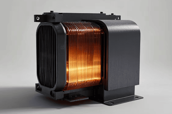
Let’s dive deeper into how core saturation affects surge current:
The Saturation-Surge Connection
-
Magnetic Flux and Core Material
- Transformer cores are designed to operate below saturation
- Sudden energization can push the core into saturation
-
Residual Magnetism
- Leftover magnetism from previous operation
- Can either increase or decrease saturation effects
-
Voltage Angle at Energization
- Worst-case scenario: energizing at voltage zero-crossing
- Can lead to maximum core saturation
Here’s a table showing the relationship between core saturation and surge current:
| Core State | Magnetizing Current | Surge Current Magnitude |
|---|---|---|
| Unsaturated | Normal (1x) | Moderate (2-4x rated) |
| Partially Saturated | Increased (2-5x) | High (4-6x rated) |
| Fully Saturated | Very High (5-10x) | Extreme (6-10x rated) |
I once worked on a project where we were commissioning a new substation. During the first energization of a large power transformer, we experienced unexpectedly high surge currents that tripped the main breaker. After investigation, we found that the core had a high level of residual magnetism from factory testing. By implementing a demagnetization procedure before energization, we significantly reduced the surge current magnitude.
To understand core saturation and its impact, consider these factors:
- Core material properties (e.g., silicon steel vs. amorphous metal)
- Design of the magnetic circuit
- Operating flux density
- Presence of DC offset in the system
It’s important to note that while core saturation is a major contributor to surge current, it’s not the only factor. System impedance, switching angle, and transformer design all play roles in determining the final surge current magnitude.
In my years of experience, I’ve found that many engineers focus solely on the electrical aspects of transformers, often overlooking the crucial role of magnetic design in surge current behavior. A holistic understanding of both electrical and magnetic phenomena is essential for effective transformer management.
What Are the Potential Risks of Excessive Surge Current in Transformers?
Imagine a river suddenly flooding its banks. The damage can be extensive and far-reaching. Excessive surge current in transformers can have similar wide-ranging impacts on your electrical system.
Excessive surge current can lead to numerous risks, including mechanical stress on windings, insulation degradation, false tripping of protection devices, and power quality issues. In severe cases, it can cause transformer failure, system instability, and even widespread power outages.
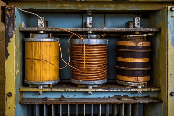
Let’s explore the potential risks in detail:
Understanding the Dangers
-
Mechanical Stress on Windings
- High currents create strong electromagnetic forces
- Can lead to winding deformation or displacement
-
Thermal Stress
- Sudden current spikes generate heat
- Accelerates insulation aging
-
Insulation Degradation
- Repeated stress weakens insulation over time
- Increases risk of internal faults
-
Protection System Malfunction
- False tripping of overcurrent relays
- Unnecessary system outages
-
Power Quality Issues
- Voltage dips during surge events
- Harmonics introduction into the system
Here’s a table summarizing the risks and their potential consequences:
| Risk | Immediate Effect | Long-term Consequence |
|---|---|---|
| Mechanical Stress | Winding movement | Reduced transformer life |
| Thermal Stress | Localized heating | Accelerated aging |
| Insulation Degradation | Partial discharges | Eventual insulation failure |
| Protection Malfunction | Nuisance tripping | Reduced system reliability |
| Power Quality Issues | Voltage fluctuations | Equipment malfunction |
I recall a case where a client experienced repeated transformer failures in a critical industrial process. Upon investigation, we discovered that frequent energization due to process requirements was causing cumulative damage from surge currents. By implementing controlled switching and adjusting the process schedule, we extended the transformer life significantly and improved overall system reliability.
When assessing the risks of surge current, consider these factors:
- Transformer size and design
- Frequency of energization events
- System fault level and impedance
- Criticality of the load being served
It’s crucial to note that while modern transformers are designed to withstand normal surge currents, repeated or excessive events can still cause cumulative damage. Regular monitoring and proper management of energization procedures are key to mitigating these risks.
In my experience, many organizations underestimate the long-term impact of surge currents, focusing only on immediate failures. A proactive approach to surge current management can lead to significant improvements in system reliability and asset longevity.
How Can You Measure Transformer Surge Current Using Simple Methods?
Ever tried to catch a lightning bolt on camera? Measuring transformer surge current can be just as tricky, but don’t worry – I’ve got some simple methods that can help.
Transformer surge current can be measured using current transformers (CTs) connected to oscilloscopes or power quality analyzers. For simpler setups, you can use peak-reading ammeters or even protection relay event records. The key is to capture the initial peak and decay pattern of the surge current.

Let’s explore some practical methods for measuring surge current:
Simple Measurement Techniques
-
Oscilloscope Method
- Use a CT to step down the current
- Connect CT output to oscilloscope
- Trigger on the energization event
-
Power Quality Analyzer
- Many modern analyzers have inrush current functions
- Can capture waveforms and provide detailed analysis
-
Peak-Reading Ammeter
- Simple but effective for magnitude measurement
- Won’t provide waveform details
-
Protection Relay Event Records
- Many digital relays can record inrush events
- Check relay manuals for this functionality
Here’s a comparison table of these methods:
| Method | Accuracy | Waveform Capture | Ease of Use | Cost |
|---|---|---|---|---|
| Oscilloscope | High | Yes | Moderate | High |
| Power Quality Analyzer | High | Yes | Easy | High |
| Peak-Reading Ammeter | Moderate | No | Very Easy | Low |
| Protection Relay Records | Moderate | Limited | Easy | Low (if already installed) |
I remember a project where we needed to measure surge currents on a large number of distribution transformers. Budget constraints meant we couldn’t use expensive equipment on every unit. We developed a hybrid approach: using a high-end power quality analyzer for detailed measurements on representative units, and simple peak-reading ammeters for quick checks on the rest. This allowed us to gather comprehensive data while staying within budget.
When measuring surge current, keep these tips in mind:
- Ensure your measurement equipment can handle the expected peak currents
- Pay attention to the CT ratio and burden
- Use appropriate safety measures – these are high-current measurements!
- Try to capture multiple energization events for a better understanding
It’s important to note that while these methods can provide valuable data, interpreting the results requires some expertise. The shape of the inrush current waveform, its decay time, and its harmonic content all provide important information about the transformer and the system it’s connected to.
In my years of field experience, I’ve found that even simple measurements can provide crucial insights. Don’t be discouraged if you don’t have access to high-end equipment – with careful setup and interpretation, even basic tools can yield valuable results.
What Factors Influence the Magnitude of Transformer Surge Current?
Have you ever wondered why some transformers seem to handle energization smoothly while others cause the lights to flicker? The answer lies in the factors that influence surge current magnitude.
The magnitude of transformer surge current is influenced by several factors, including the point-on-wave of energization, residual flux in the core, system impedance, and transformer design characteristics. Understanding these factors is crucial for predicting and managing surge currents effectively.
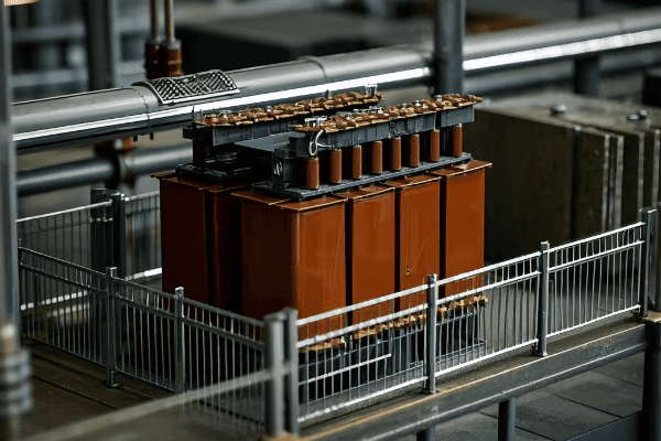
Let’s dive into the key factors that affect surge current magnitude:
Critical Influencing Factors
-
Point-on-Wave of Energization
- Timing of switch closure relative to voltage waveform
- Worst case: closing at voltage zero-crossing
-
Residual Flux in the Core
- Magnetism left in the core from previous operation
- Can either add to or subtract from the surge current
-
System Impedance
- Lower impedance leads to higher surge currents
- Includes source impedance and line impedance
-
Transformer Design
- Core material and design (e.g., shell-type vs. core-type)
- Winding configuration and impedance
Here’s a table summarizing these factors and their impacts:
| Factor | Low Impact Scenario | High Impact Scenario |
|---|---|---|
| Point-on-Wave | Energized at peak voltage | Energized at zero voltage |
| Residual Flux | Opposing incoming flux | Aiding incoming flux |
| System Impedance | High impedance source | Low impedance source |
| Transformer Design | High impedance, modern core | Low impedance, traditional core |
I recall a case where we were troubleshooting excessive surge currents in a industrial plant. Initial assumptions pointed to the transformers, but after careful analysis, we discovered that recent system upgrades had significantly reduced the source impedance. This lower impedance was allowing much higher surge currents. By adjusting the switching strategy and adding series reactors, we were able to bring the surge currents back to acceptable levels.
When analyzing surge current factors, consider these points:
- The worst-case scenario often involves a combination of factors
- System changes can have unexpected impacts on surge current behavior
- Modern transformers often have design features to mitigate surge currents
- Operational practices can significantly influence surge current magnitude
It’s crucial to understand that while some factors (like transformer design) are fixed, others (like point-on-wave switching) can be controlled. This gives us opportunities to manage surge currents even in existing systems.
In my experience, many engineers focus solely on the transformer when dealing with surge current issues. However, a holistic approach considering all system factors often leads to more effective and economical solutions. Remember, the transformer is just one part of a larger electrical ecosystem.
How Can You Mitigate the Effects of Surge Current in Power Transformers?
Dealing with transformer surge current can feel like trying to tame a wild beast. But don’t worry – I’ve got some proven strategies to help you keep this electrical monster under control.
Mitigating surge current effects involves a combination of design choices, operational strategies, and additional equipment. Key approaches include controlled switching, pre-insertion resistors, neutral earthing resistors, and proper transformer design. The goal is to reduce the peak magnitude and duration of the surge current.
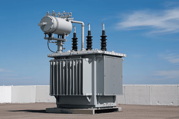
Let’s explore some effective mitigation strategies:
Proven Mitigation Techniques
-
Controlled Switching
- Energize at optimal point-on-wave
- Requires specialized switching devices
-
Pre-insertion Resistors
- Temporarily insert resistance during energization
- Limits initial current surge
-
Neutral Earthing Resistors
- Reduces zero-sequence inrush current
- Particularly effective for delta-wye transformers
-
Transformer Design Optimization
- Use of low-loss core materials
- Proper selection of core flux density
-
Soft-start Techniques
- Gradual voltage ramp-up
- Often used in motor-generator sets
Here’s a comparison table of these mitigation methods:
| Method | Effectiveness | Cost | Complexity | Applicability |
|---|---|---|---|---|
| Controlled Switching | High | Moderate | Moderate | Wide |
| Pre-insertion Resistors | High | Moderate | Low | Specific cases |
| Neutral Earthing Resistors | Moderate | Low | Low | Grounded systems |
| Design Optimization | Moderate | Varies | High | New transformers |
| Soft-start Techniques | High | High | High | Special applications |
I remember a project where we were dealing with nuisance tripping in a critical power system due to surge currents. After analyzing the system, we implemented a combination of controlled switching and pre-insertion resistors. The results were dramatic – we reduced the peak surge current by over 50% and completely eliminated the tripping issues. The client was thrilled with the improved reliability.
When implementing surge current mitigation, keep these points in mind:
- No single solution fits all situations – often a combination is best
- Consider both the technical and economic aspects of each solution
- Some methods (like controlled switching) can have benefits beyond surge reduction
- Regular system studies are crucial as network changes can affect surge behavior
It’s important to note that while mitigation techniques can significantly reduce surge currents, they can’t eliminate them entirely. The goal is to bring the surge current within acceptable limits for your specific system and equipment.
In my years of experience, I’ve found that a proactive approach to surge current management can save significant costs in the long run. It’s not just about preventing failures – it’s about optimizing system performance, extending equipment life, and improving overall reliability.
One case that stands out in my memory involved a large data center. They were experiencing frequent issues with their UPS systems due to transformer inrush currents. We implemented a comprehensive mitigation strategy that included:
- Replacing older transformers with modern, low-inrush designs
- Installing controlled switching devices on critical feeders
- Implementing a staged energization procedure for large loads
The results were impressive. Not only did we eliminate the UPS issues, but we also saw a marked improvement in overall power quality. The client reported a 30% reduction in their annual maintenance costs for power equipment.
When considering surge current mitigation, it’s crucial to take a system-wide approach. Here’s a step-by-step strategy I often recommend:
-
Conduct a System Study
- Analyze existing surge current levels
- Identify critical points in the network
-
Set Clear Objectives
- Define acceptable surge current limits
- Consider both equipment protection and operational needs
-
Evaluate Mitigation Options
- Consider technical feasibility and cost-effectiveness
- Look for solutions that offer multiple benefits
-
Implement in Phases
- Start with the most critical or problematic areas
- Monitor and adjust as you go
-
Regular Review and Adjustment
- Power systems evolve – your mitigation strategy should too
- Conduct periodic reviews to ensure ongoing effectiveness
Remember, managing surge currents is not a one-time task. It’s an ongoing process that requires attention and adaptation as your power system changes and grows.
Conclusion
Understanding and managing transformer surge current is crucial for maintaining reliable and efficient power systems. By considering the causes, risks, measurement techniques, influencing factors, and mitigation strategies, we can effectively control this phenomenon and ensure the longevity of our electrical infrastructure.
Have you ever wondered what would happen if lightning struck your power transformer? The consequences could be devastating without proper protection.
Selecting the perfect high-voltage lightning arrester for transformer protection involves considering five key factors: voltage rating, arrester type, energy rating, operating voltage, and environmental conditions. By carefully evaluating these aspects, you can ensure optimal protection for your transformer against lightning strikes and power surges.
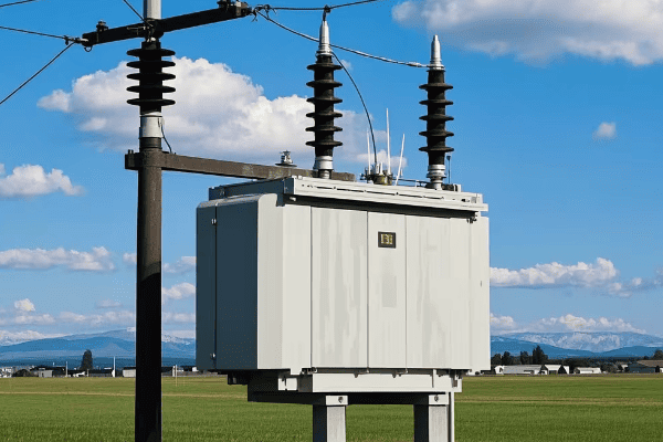
As someone who’s spent years in the power industry, I’ve seen firsthand the importance of choosing the right lightning arrester. Let’s dive into the key factors you need to consider to keep your transformers safe and your power flowing.
What Voltage Rating Do You Need for Your Lightning Arrester?
Imagine buying a fire extinguisher that can’t handle the heat of your kitchen fire. That’s what happens when you choose a lightning arrester with the wrong voltage rating.
The voltage rating of your lightning arrester should be at least 1.2 times the maximum operating voltage of your transformer. This ensures adequate protection against voltage surges. For example, if your transformer operates at 100 kV, your lightning arrester should have a voltage rating of at least 120 kV.
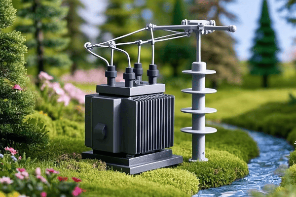
Let’s break down the process of determining the right voltage rating:
Factors to Consider When Choosing Voltage Rating
-
Transformer’s Maximum Operating Voltage
- This is your starting point. Always check the transformer’s specifications.
- Remember, it’s the maximum voltage, not the nominal voltage.
-
System’s Highest Voltage Level
- Consider any potential voltage fluctuations in your power system.
- It’s better to err on the side of caution here.
-
Temporary Overvoltage Conditions
- Account for any known overvoltage scenarios in your system.
- This could be due to load rejection or other system anomalies.
-
Safety Margin
- The 1.2 multiplier we mentioned earlier? That’s your safety margin.
- It accounts for unexpected voltage spikes and system variations.
Here’s a simple table to help you visualize the process:
| Transformer Operating Voltage (kV) | Minimum Arrester Voltage Rating (kV) |
|---|---|
| 69 | 83 |
| 138 | 166 |
| 230 | 276 |
| 345 | 414 |
| 500 | 600 |
I remember a case where a client insisted on using a lower-rated arrester to save costs. Despite my warnings, they went ahead. Six months later, a lightning strike caused significant damage to their transformer. The repair costs far exceeded what they would have spent on a properly rated arrester. It was a costly lesson in the importance of correct voltage rating.
When selecting your arrester’s voltage rating, always consult with the manufacturer and consider any unique aspects of your power system. It’s better to have a slightly over-rated arrester than one that can’t handle the job when you need it most.
Metal Oxide vs. Gap Type: Which Arrester is Right for Your Transformer?
Choosing between metal oxide and gap type arresters is like deciding between a smartphone and a flip phone. Both make calls, but one offers significantly more advanced protection.
Metal oxide arresters are generally superior to gap type arresters for transformer protection. They offer faster response times, better energy handling capabilities, and more consistent performance. However, gap type arresters may still be suitable in certain low-risk or budget-constrained situations.
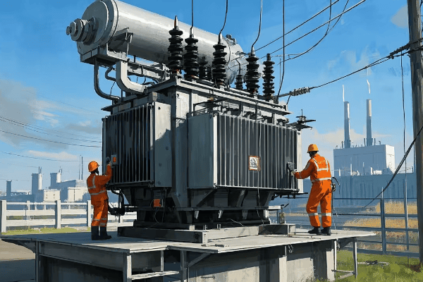
Let’s dive deeper into the characteristics of each type:
Understanding Metal Oxide Arresters
-
Fast Response Time
- Metal oxide arresters react in nanoseconds to voltage surges.
- This rapid response is crucial for protecting sensitive equipment.
-
Excellent Energy Handling
- They can absorb large amounts of energy without damage.
- This makes them ideal for areas with frequent lightning strikes.
-
No Follow Current
- Metal oxide arresters don’t produce a follow current after operation.
- This reduces stress on the power system and improves reliability.
-
Compact Design
- These arresters are smaller and lighter than gap types.
- This makes installation and maintenance easier.
Gap Type Arresters: The Old Guard
-
Simple Construction
- Gap type arresters have a straightforward design.
- This can make them more affordable in some cases.
-
Visible Operation
- You can often see when a gap type arrester has operated.
- This can be helpful for maintenance and troubleshooting.
-
Limited Performance
- They have slower response times compared to metal oxide arresters.
- Energy handling capabilities are generally lower.
-
Follow Current Issues
- Gap type arresters can produce a follow current after operation.
- This can stress the power system and potentially cause issues.
Here’s a comparison table to help you decide:
| Feature | Metal Oxide Arrester | Gap Type Arrester |
|---|---|---|
| Response Time | Nanoseconds | Microseconds |
| Energy Handling | High | Moderate |
| Follow Current | None | Yes |
| Size | Compact | Bulky |
| Cost | Higher | Lower |
| Lifespan | Longer | Shorter |
I once worked on a project upgrading a substation’s protection system. The client was using old gap type arresters and experiencing frequent issues with follow currents and occasional equipment damage. We replaced them with metal oxide arresters, and the improvement was immediate. Not only did we see a reduction in equipment stress, but the overall reliability of the substation increased significantly.
When choosing between metal oxide and gap type arresters, consider these factors:
- The criticality of the equipment you’re protecting
- The lightning activity in your area
- Your budget constraints
- The expected lifespan of your installation
In most cases, I recommend metal oxide arresters for their superior performance and reliability. However, if you’re dealing with a low-risk installation or severe budget constraints, gap type arresters might still be a viable option. Always consult with a protection expert to make the best choice for your specific situation.
How to Determine the Ideal Energy Rating for Your Lightning Arrester?
Choosing the right energy rating for your lightning arrester is like picking the right size fire extinguisher. Too small, and it won’t handle the job. Too big, and you’re wasting money.
The ideal energy rating for your lightning arrester depends on factors like the lightning activity in your area, the importance of the protected equipment, and the system voltage. A higher energy rating means better protection but also higher cost. For most transformer applications, an energy rating between 5-20 kJ/kV is typical.
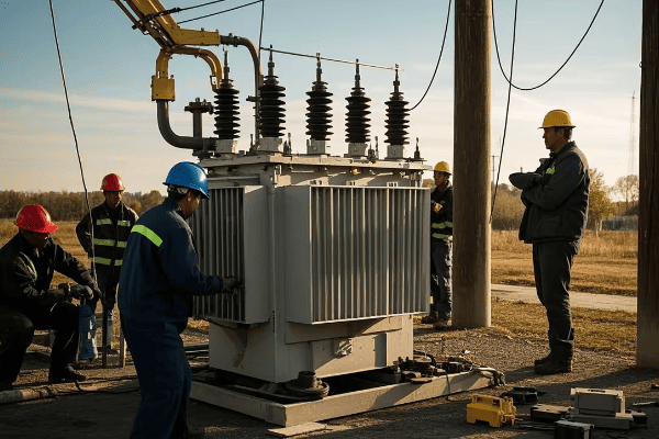
Let’s break down how to determine the right energy rating:
Factors Influencing Energy Rating Selection
-
Lightning Activity Level
- Areas with frequent and severe lightning require higher energy ratings.
- Consider both the frequency and intensity of lightning strikes.
-
System Voltage
- Higher voltage systems generally require arresters with higher energy ratings.
- This is due to the increased energy in potential surges.
-
Equipment Criticality
- More critical equipment justifies higher energy ratings for better protection.
- Consider the cost and importance of the protected transformer.
-
System Grounding
- Effectively grounded systems may allow for lower energy ratings.
- Poorly grounded systems require higher ratings to compensate.
-
Arrester Location
- Arresters at line entrances may need higher ratings than those deeper in the system.
- This is due to the higher exposure to direct lightning strikes.
Here’s a table to guide your energy rating selection:
| System Voltage (kV) | Minimum Energy Rating (kJ/kV) | Recommended Energy Rating (kJ/kV) |
|---|---|---|
| Up to 69 | 3 | 5-10 |
| 69-230 | 5 | 10-15 |
| Above 230 | 8 | 15-20 |
I recall a project where we were protecting a critical transformer for a data center. Despite the higher cost, we opted for an arrester with a 20 kJ/kV energy rating due to the area’s high lightning activity and the critical nature of the load. During a particularly severe thunderstorm season, this decision paid off. The arrester successfully protected the transformer from multiple severe strikes, preventing what could have been catastrophic downtime for the data center.
When selecting your arrester’s energy rating, consider these tips:
- Always err on the side of caution for critical equipment.
- Consider future system expansions or voltage upgrades.
- Consult local weather data for lightning activity information.
- Don’t forget to factor in switching surges, not just lightning.
Remember, while a higher energy rating provides better protection, it also comes with a higher price tag. Balance the need for protection with your budget constraints, but never compromise on safety for critical equipment.
What Operating Voltage Range Should You Consider for Optimal Protection?
Selecting the right operating voltage range for your lightning arrester is like tuning a radio. Too low, and you’ll get unwanted noise. Too high, and you’ll miss the important signals.
The operating voltage range of a lightning arrester should be carefully matched to your system’s normal operating voltage and potential temporary overvoltages. Typically, the arrester’s maximum continuous operating voltage (MCOV) should be about 5-10% higher than the system’s maximum continuous operating voltage.
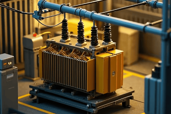
Let’s explore how to determine the optimal operating voltage range:
Key Considerations for Operating Voltage Range
-
System’s Normal Operating Voltage
- This is your baseline. Start by knowing your system’s typical voltage.
- Remember, this can fluctuate within a certain range.
-
Temporary Overvoltage Conditions
- Account for known overvoltage scenarios in your system.
- These could be due to load rejection, switching operations, or other factors.
-
Arrester’s Protective Level
- The arrester must operate below the insulation withstand level of the protected equipment.
- This ensures the arrester acts before equipment damage occurs.
-
Margin of Safety
- Allow for a safety margin above normal system voltage.
- This prevents nuisance operations during minor voltage fluctuations.
Here’s a table to guide your operating voltage range selection:
| System Voltage (kV) | Recommended MCOV Range (kV) | Typical Protective Level (kV) |
|---|---|---|
| 69 | 70-76 | 220-240 |
| 138 | 140-152 | 350-380 |
| 230 | 233-253 | 540-580 |
| 345 | 349-379 | 750-810 |
| 500 | 506-549 | 1050-1150 |
I once worked on a project where we were experiencing frequent arrester operations in a 138 kV system. After investigation, we found that the arrester’s MCOV was set too close to the system’s normal operating voltage. By selecting an arrester with a slightly higher MCOV, we eliminated the nuisance operations while still maintaining adequate protection.
When selecting your arrester’s operating voltage range, keep these points in mind:
- Always consult your system’s voltage profile, including any known overvoltage scenarios.
- Consider future system upgrades that might increase operating voltages.
- Balance protection level with the need to avoid nuisance operations.
- Remember that higher MCOV ratings often come with higher protective levels, so there’s a trade-off to consider.
The right operating voltage range ensures your arrester provides reliable protection without unnecessary operations. It’s a critical factor in maximizing the effectiveness and lifespan of your lightning protection system.
How Do Environmental Factors Influence Your Lightning Arrester Choice?
Choosing a lightning arrester without considering environmental factors is like buying a car without thinking about the roads you’ll drive on. The environment can make or break your protection strategy.
Environmental factors such as pollution, humidity, temperature extremes, and altitude can significantly impact the performance and lifespan of lightning arresters. These factors influence the choice of housing material, creepage distance, and even the internal components of the arrester.
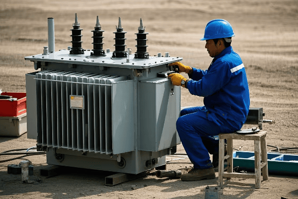
Let’s explore how different environmental factors affect your arrester choice:
Key Environmental Considerations
-
Pollution Level
- High pollution areas require arresters with higher creepage distances.
- Special coatings or designs may be necessary to prevent flashover.
-
Humidity and Rainfall
- High humidity can lead to corrosion and degradation of arrester components.
- Proper sealing and moisture-resistant materials are crucial in wet environments.
-
Temperature Extremes
- Both very high and very low temperatures can affect arrester performance.
- Choose arresters rated for your specific temperature range.
-
Altitude
- Higher altitudes require derating of arrester voltage ratings.
- This is due to the reduced air density at high elevations.
-
UV Radiation
- Strong sunlight can degrade certain housing materials over time.
- UV-resistant housings are important in areas with high sun exposure.
Here’s a table summarizing environmental factors and their impacts:
| Environmental Factor | Impact on Arrester | Mitigation Strategy |
|---|---|---|
| High Pollution | Increased risk of flashover | Higher creepage distance, special coatings |
| High Humidity | Corrosion, internal degradation | Enhanced sealing, moisture-resistant materials |
| Extreme Temperatures | Altered performance, material stress | Temperature-rated designs, special materials |
| High Altitude | Reduced voltage withstand | Voltage derating, special designs |
| Strong UV Radiation | Housing degradation | UV-resistant materials |
I remember a project in a coastal industrial area where standard arresters were failing prematurely. The combination of salt spray, industrial pollution, and high humidity was wreaking havoc on the arrester housings. We switched to arresters with silicon rubber housings and increased creepage distances. The result was a dramatic improvement in reliability and lifespan.
When considering environmental factors, keep these tips in mind:
- Always conduct a thorough site survey before selecting arresters.
- Consider seasonal variations in environmental conditions.
- Don’t forget about micro-environments (e.g., near cooling towers or in valleys).
- Consult with arrester manufacturers about their recommendations for specific environments.
Remember, the most advanced arrester technology is useless if it can’t withstand the environment it’s placed in. Proper environmental consideration ensures your lightning protection system remains effective year after year, regardless of the conditions it faces.
Installation and Maintenance: Best Practices for Lightning Arrester Effectiveness
Installing a lightning arrester isn’t a "set it and forget it" task. Proper installation and regular maintenance are like servicing your car – essential for long-term performance and reliability.
Correct installation and consistent maintenance are crucial for the effectiveness of lightning arresters. This includes proper grounding, secure mounting, regular inspections, and timely replacements. Good practices can significantly extend the life of your arresters and ensure they perform when you need them most.
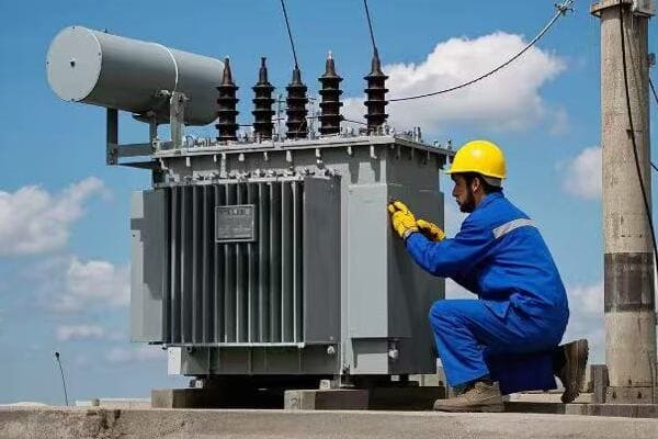
Let’s dive into the best practices for installation and maintenance:
Installation Best Practices
-
Proper Grounding
- Ensure a low-impedance path to ground.
- Use short, straight leads with minimal bends.
-
Secure Mounting
- Mount arresters vertically unless otherwise specified.
- Ensure they’re securely fastened to withstand environmental forces.
-
Lead Length
- Keep lead lengths as short as possible.
- Long leads can reduce the effectiveness of the arrester.
-
Clearances
- Maintain proper clearances from other equipment.
- This prevents flashover and ensures safe operation.
Maintenance Best Practices
-
Regular Visual Inspections
- Check for physical damage, corrosion, or signs of previous operations.
- Inspect at least annually, more frequently in harsh environments.
-
Electrical Testing
- Conduct periodic tests to ensure proper operation.
- This may include insulation resistance and leakage current tests.
-
Thermal Imaging
- Use thermal cameras to detect hot spots or abnormal heating.
- This can identify potential issues before they become critical.
-
Record Keeping
- Maintain detailed records of inspections and tests. – This helps track performance over time and predict potential issues.
-
Timely Replacement
- Replace arresters that show signs of degradation or have reached their end of life.
- Don’t wait for failure – proactive replacement is key.
Here’s a maintenance schedule table to help you stay on track:
| Maintenance Task | Frequency | Importance |
|---|---|---|
| Visual Inspection | Every 6 months | High |
| Electrical Testing | Annually | Critical |
| Thermal Imaging | Annually | Medium |
| Record Update | After each inspection/test | High |
| Full System Review | Every 3-5 years | Critical |
I recall a situation where a client was experiencing frequent arrester failures. Upon investigation, we found that their installation practices were subpar – long ground leads and improper mounting were compromising the arresters’ effectiveness. After correcting these issues and implementing a rigorous maintenance schedule, their failure rate dropped dramatically.
When it comes to installation and maintenance, keep these tips in mind:
- Always follow manufacturer guidelines for installation and maintenance.
- Train your staff on proper inspection techniques.
- Invest in quality testing equipment for accurate assessments.
- Don’t neglect seemingly minor issues – they can lead to major problems.
- Consider the environment when planning maintenance schedules.
Remember, even the best lightning arrester is only as good as its installation and maintenance. A well-maintained system not only protects your equipment but also provides peace of mind during those stormy nights.
Conclusion
Selecting the perfect high-voltage lightning arrester for your transformer is a critical task that requires careful consideration of voltage ratings, arrester types, energy ratings, operating voltage ranges, and environmental factors. Proper installation and maintenance are equally important for long-term effectiveness. By following these guidelines, you can ensure optimal protection for your valuable transformer assets.
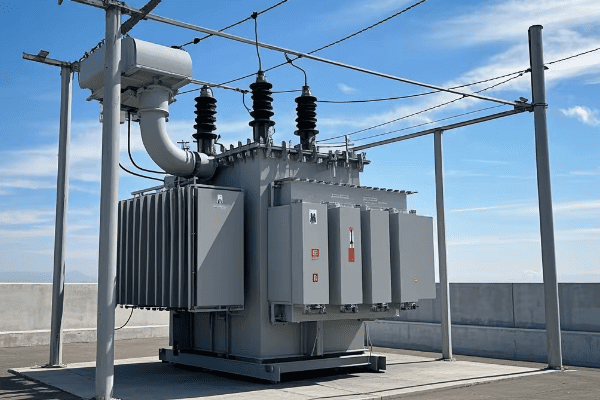
Have you ever wondered why sometimes power transformers behave unexpectedly when switched on? The answer might lie in a phenomenon called transformer remanence.
Transformer remanence is the residual magnetism left in a transformer’s core after DC current is removed. It can cause issues like inrush currents, relay malfunctions, and even transformer damage. Understanding remanence is crucial for maintaining power system stability and safety.

As someone who’s spent years working with power systems, I’ve seen firsthand how remanence can impact transformer performance. Let’s dive into this critical yet often overlooked aspect of power engineering.
How Does Transformer Remanence Occur? The Science Behind the Magnetism
Picture this: you’ve just finished a routine DC resistance test on a power transformer. Everything seems fine, but there’s an invisible change within the transformer’s core. That’s remanence at work.
Transformer remanence occurs due to the hysteresis characteristics of the transformer’s ferromagnetic core. When DC current is applied during tests like winding resistance measurements, it magnetizes the core. After the current is removed, some magnetic flux remains, creating remanence.

Let’s break down the process of remanence formation:
The Journey from Test to Trouble
- DC Test Application: During routine maintenance, DC current is applied to the transformer windings.
- Core Magnetization: The DC current magnetizes the transformer’s iron core.
- Current Removal: When the test is complete, the DC current is switched off.
- Residual Magnetism: Some magnetic flux remains in the core due to its ferromagnetic properties.
Here’s a simple table illustrating the factors affecting remanence:
| Factor | Effect on Remanence | Why It Matters |
|---|---|---|
| DC Current Magnitude | Higher current = More remanence | Affects test procedures |
| Duration of DC Application | Longer duration = More remanence | Impacts maintenance schedules |
| Core Material Properties | Different materials retain varying levels of magnetism | Influences transformer design |
I remember a case where we were commissioning a new substation. During the first energization of a large power transformer, we experienced unexpected protection trips. After investigation, we found that high remanence from factory tests was the culprit. It was a stark reminder of how important it is to consider remanence in our procedures.
What Are the Hazards of Transformer Remanence? Unveiling the Risks
You might think a little leftover magnetism is no big deal. But in the world of power transformers, remanence can lead to some serious problems. Let’s explore the risks.
Transformer remanence can cause several hazards, including large inrush currents during energization, potential relay misoperations, increased reactive power consumption, and even damage to the transformer or connected equipment. These issues can lead to system instability and significant economic losses.
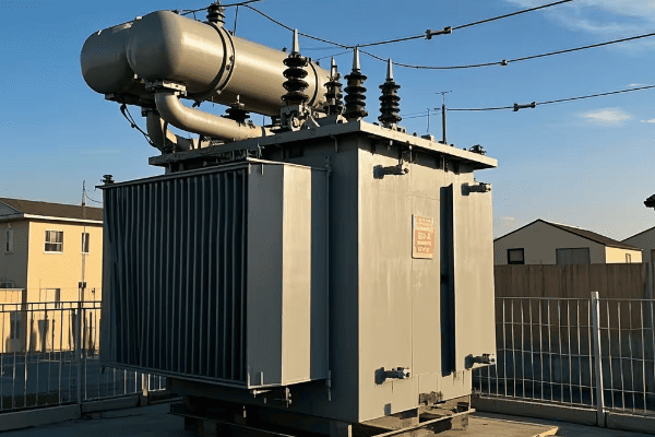
Let’s dive deeper into these hazards:
The Ripple Effects of Remanence
-
Inrush Current Amplification
- What happens: Remanence causes core saturation, leading to extremely high inrush currents.
- Consequences: Potential tripping of protection devices, stress on windings.
-
Relay Misoperation
- What happens: High inrush currents can be mistaken for fault conditions.
- Consequences: Unnecessary outages, reduced system reliability.
-
Increased Reactive Power Consumption
- What happens: Saturated core draws more reactive power.
- Consequences: Reduced system efficiency, potential voltage stability issues.
-
Transformer Overheating
- What happens: Core saturation increases stray flux, heating metal parts.
- Consequences: Accelerated insulation aging, reduced transformer lifespan.
Here’s a table summarizing these hazards:
| Hazard | Direct Impact | Long-term Consequences |
|---|---|---|
| Inrush Currents | Stress on windings, nuisance tripping | Reduced transformer life |
| Relay Misoperation | Unnecessary outages | Decreased system reliability |
| Reactive Power Increase | System inefficiency | Voltage stability issues |
| Overheating | Insulation degradation | Shortened transformer lifespan |
I once worked on a project where a utility was experiencing frequent, unexplained outages in a particular substation. After extensive investigation, we discovered that remanence in one of the transformers was causing protection relays to misoperate. By implementing proper demagnetization procedures, we were able to solve the issue and significantly improve system reliability.
How Can We Mitigate Transformer Remanence? Strategies for Safe Operation
Now that we understand the risks, you’re probably wondering how we can deal with remanence. Don’t worry, I’ve got you covered with some practical strategies.
To mitigate transformer remanence, several techniques can be employed. These include controlled switching, core demagnetization procedures, and the use of advanced transformer designs. Proper maintenance practices and awareness of remanence effects are also crucial in managing this issue.
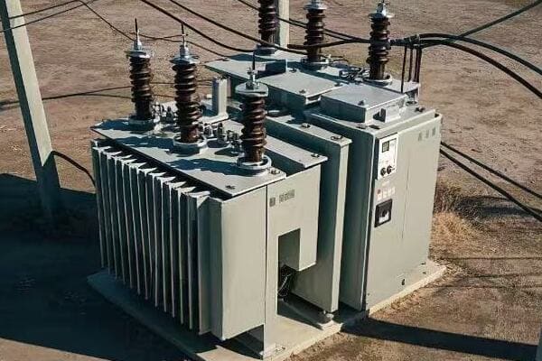
Let’s explore these mitigation strategies in detail:
Taming the Magnetic Beast
-
Controlled Switching
- How it works: Energizes the transformer at the optimal point of the voltage wave.
- Benefits: Reduces inrush currents, minimizes stress on the system.
-
Core Demagnetization
- How it works: Applies alternating current with decreasing magnitude to the windings.
- Benefits: Removes residual magnetism before energization.
-
Advanced Transformer Designs
- How it works: Uses core materials and designs that minimize remanence.
- Benefits: Reduces the likelihood of remanence-related issues.
-
Proper Maintenance Practices
- How it works: Includes remanence considerations in testing and maintenance procedures.
- Benefits: Prevents inadvertent creation of high remanence levels.
Here’s a comparison of these mitigation strategies:
| Strategy | Effectiveness | Implementation Difficulty | Cost |
|---|---|---|---|
| Controlled Switching | High | Moderate | Moderate |
| Core Demagnetization | Very High | Low | Low |
| Advanced Designs | High | High (for new transformers) | High |
| Maintenance Practices | Moderate | Low | Low |
In my experience, a combination of these strategies works best. I recall a large industrial client who was struggling with frequent transformer trips. We implemented a comprehensive approach: installing controlled switching devices, developing a demagnetization procedure for maintenance activities, and training staff on remanence awareness. The results were impressive – a 90% reduction in remanence-related issues over the following year.
When dealing with remanence, keep these tips in mind:
- Always consider remanence when planning transformer energization.
- Invest in training for maintenance staff on remanence effects and mitigation.
- Regular monitoring and assessment of transformer behavior can help identify remanence issues early.
Remember, addressing remanence is not just about preventing problems – it’s about ensuring the long-term health and efficiency of your power system.
Conclusion
Transformer remanence is a complex but manageable aspect of power system operation. By understanding its causes, recognizing its hazards, and implementing effective mitigation strategies, we can significantly improve the reliability and efficiency of our power systems. As we continue to rely more heavily on electrical power, managing remanence will only become more crucial. Stay informed, stay prepared, and keep your transformers running smoothly.
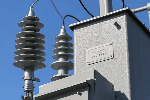
Have you ever worried about your expensive electrical equipment getting fried during a thunderstorm? I know I have. That’s where lightning arresters come in.
A lightning arrester is a device that protects electrical systems from lightning strikes. It works by diverting the high voltage from lightning to the ground, keeping your equipment safe. Think of it as a superhero for your electrical system, always on guard against nature’s fury.
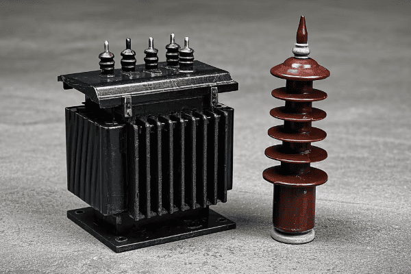
As someone who’s spent years in the power industry, I’ve seen firsthand how crucial these devices are. Let’s dive into the world of lightning arresters and discover why they’re so important for our electrical systems.
How Does a Lightning Arrester Work? Understanding the Basics
Picture this: you’re in the middle of an important project, and suddenly, a massive thunderstorm rolls in. Your heart races, thinking about all your expensive equipment. But with a lightning arrester, you can breathe easy.
A lightning arrester works by creating a low-resistance path for lightning current to flow safely to the ground. When lightning strikes, the arrester quickly diverts the surge away from your equipment. It’s like a traffic cop, redirecting dangerous electrical traffic to keep your system safe.
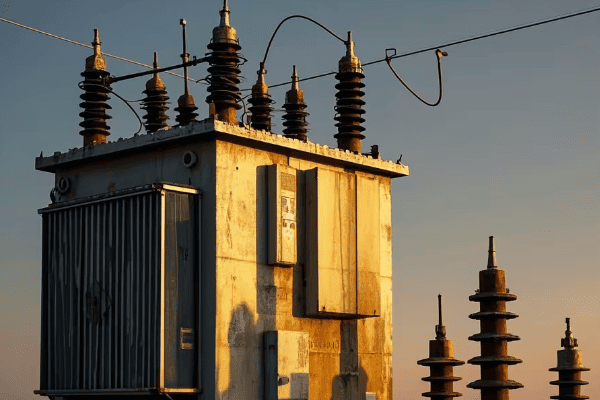
Let’s break down how these amazing devices work:
The Three Stages of Lightning Protection
- Detection: The arrester is always on alert, monitoring the voltage in your system.
- Diversion: When it detects a surge, it springs into action, creating a path of least resistance.
- Recovery: After the danger has passed, it goes back to its normal state, ready for the next strike.
Here’s a simple table to illustrate the process:
| Stage | What Happens | Why It’s Important |
|---|---|---|
| Detection | Arrester senses voltage spike | Rapid response is crucial |
| Diversion | Creates low-resistance path | Protects equipment from damage |
| Recovery | Returns to normal state | Ensures continuous protection |
I remember a time when I was working on a power substation project. We had just installed new lightning arresters, and that very night, a massive storm hit. The next day, we found that while nearby buildings had suffered damage, our substation was completely unscathed. It was a powerful demonstration of how effective these devices can be.
Types of Lightning Arresters: Which One Do You Need?
Choosing the right lightning arrester can feel like navigating a maze. With so many options out there, how do you know which one is right for your needs?
There are several types of lightning arresters, each designed for specific applications. The main types include metal oxide varistors (MOV), gas discharge tubes, and silicon avalanche diodes. Your choice depends on factors like voltage level, exposure risk, and the equipment you’re protecting.
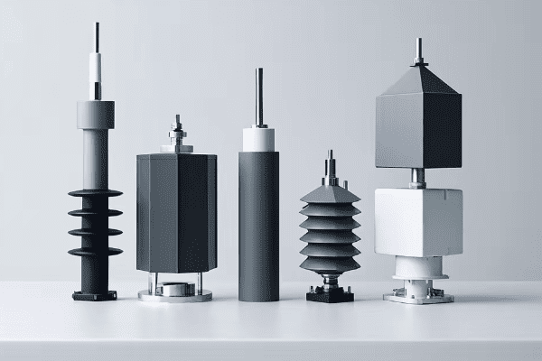
Let’s explore the different types and their best uses:
Comparing Lightning Arrester Types
-
Metal Oxide Varistors (MOV)
- Best for: High-voltage applications
- How they work: Use metal oxide elements to absorb surge energy
- Pros: Fast response, high energy absorption
-
Gas Discharge Tubes
- Best for: Telecommunications equipment
- How they work: Use ionized gas to create a short circuit during surges
- Pros: Long lifespan, can handle repeated strikes
-
Silicon Avalanche Diodes
- Best for: Low-voltage, sensitive electronics
- How they work: Use semiconductor technology to clamp voltage
- Pros: Very fast response, precise voltage control
Here’s a comparison table to help you choose:
| Type | Voltage Range | Response Time | Best Application |
|---|---|---|---|
| MOV | 100V – 1MV | Nanoseconds | Power distribution |
| Gas Discharge | 90V – 1000V | Microseconds | Telecom systems |
| Silicon Diodes | 5V – 400V | Picoseconds | Computer equipment |
In my experience, I’ve found that MOVs are the workhorses of the industry. I once worked on a project for a large data center. We chose MOV arresters for their main power lines due to their high energy absorption capacity. The client was initially skeptical about the cost, but after a particularly stormy season with zero equipment damage, they were more than convinced of the investment’s value.
Where to Install Lightning Arresters for Maximum Protection?
You’ve got your lightning arrester, but where should you put it? This is a question I get all the time, and it’s crucial for ensuring maximum protection.
Lightning arresters should be installed at key points in your electrical system where surges are likely to enter. This typically includes service entrances, main distribution panels, and near sensitive equipment. The goal is to create a multi-layered defense against lightning strikes.
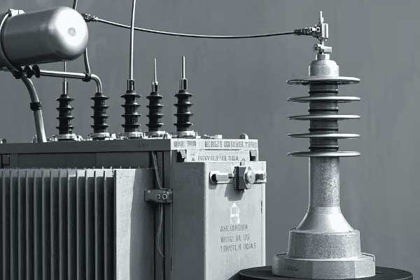
Let’s look at the best places to install lightning arresters:
Strategic Placement for Comprehensive Protection
-
Service Entrance
- Why here? It’s the first line of defense
- What it protects: Your entire electrical system
-
Main Distribution Panel
- Why here? Provides secondary protection
- What it protects: Branch circuits and downstream equipment
-
Near Sensitive Equipment
- Why here? Offers localized protection
- What it protects: Specific valuable or vulnerable devices
-
Outdoor Structures
- Why here? Protects against direct strikes
- What it protects: Antennas, HVAC units, outdoor lighting
Here’s a table showing the benefits of each installation point:
| Location | Protection Level | Equipment Safeguarded |
|---|---|---|
| Service Entrance | Primary | Whole building system |
| Distribution Panel | Secondary | Major appliances, circuits |
| Near Equipment | Tertiary | Computers, servers, etc. |
| Outdoor | Direct Strike | External systems |
I remember a project I worked on for a hospital. We installed arresters at multiple points throughout their electrical system. During a severe thunderstorm, the hospital’s critical equipment remained operational, potentially saving lives. It was a powerful reminder of why proper placement is so important.
When installing arresters, consider these factors:
- Proximity to protected equipment
- Grounding system quality
- Local lightning activity levels
- Building structure and materials
Remember, a well-planned arrester system is like a fortress, protecting your electrical equipment from all angles.
Lightning Arrester vs. Surge Protector: What’s the Difference?
I often hear people use the terms "lightning arrester" and "surge protector" interchangeably. But are they really the same thing? Let’s clear up this common confusion.
Lightning arresters and surge protectors are both protective devices, but they serve different purposes. Lightning arresters handle massive, short-duration surges from lightning strikes, while surge protectors deal with smaller, more frequent power surges from various sources. Think of arresters as bodyguards and surge protectors as bouncers.
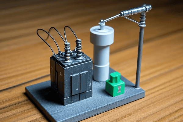
Let’s break down the key differences:
Understanding the Distinctions
-
Purpose
- Lightning Arrester: Protects against lightning strikes
- Surge Protector: Guards against smaller, everyday power surges
-
Capacity
- Lightning Arrester: Handles extremely high voltages (thousands of volts)
- Surge Protector: Manages lower voltage surges (hundreds of volts)
-
Response Time
- Lightning Arrester: Reacts in nanoseconds
- Surge Protector: Typically slower response
-
Installation
- Lightning Arrester: Usually installed at service entrance or distribution panel
- Surge Protector: Can be installed at outlets or as whole-house units
Here’s a comparison table to illustrate the differences:
| Feature | Lightning Arrester | Surge Protector |
|---|---|---|
| Voltage Handled | 10,000V+ | Up to 6,000V |
| Duration of Protection | Microseconds | Continuous |
| Typical Use | Outdoor, industrial | Indoor, residential |
| Cost | Higher | Lower |
I once worked on a project where a client had only installed surge protectors, thinking they were fully protected against lightning. After a direct strike caused significant damage, we added proper lightning arresters to their system. It was a costly lesson in understanding the difference between these two devices.
When designing a comprehensive protection system, I always recommend using both:
- Lightning arresters for primary protection against major strikes
- Surge protectors for secondary defense against smaller, frequent surges
This layered approach provides the best overall protection for your electrical system.
Maintenance of Lightning Arresters: Ensuring Long-Term Effectiveness
You’ve invested in lightning arresters, but how do you make sure they keep doing their job year after year? This is a critical question that many people overlook.
Regular maintenance of lightning arresters is crucial for their long-term effectiveness. This includes visual inspections, electrical tests, and timely replacements. Proper maintenance ensures your arresters are always ready to protect your system when lightning strikes.
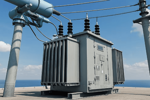
Let’s dive into the key aspects of maintaining your lightning arresters:
Essential Maintenance Practices
-
Visual Inspections
- Frequency: At least annually
- What to look for: Physical damage, corrosion, loose connections
-
Electrical Testing
- Frequency: Every 2-3 years
- Tests to perform: Insulation resistance, leakage current
-
Thermal Imaging
- Frequency: Annually
- Purpose: Detect hot spots indicating potential issues
-
Record Keeping
- Importance: Tracks performance over time
- What to record: Test results, visual inspection findings, any repairs
Here’s a maintenance schedule table to help you stay on track:
| Maintenance Task | Frequency | Importance |
|---|---|---|
| Visual Inspection | Annually | High |
| Electrical Testing | Every 2-3 Years | Critical |
| Thermal Imaging | Annually | Medium |
| Record Updating | After Each Check | High |
I recall a situation where a client neglected their arrester maintenance. During a routine check, we found several arresters had degraded significantly. We replaced them just in time before a major storm hit the area. It was a close call that highlighted the importance of regular maintenance.
When maintaining your arresters, keep these tips in mind:
- Always follow manufacturer guidelines
- Use qualified technicians for testing and repairs
- Keep spare parts on hand for quick replacements
- Consider environmental factors that may affect arrester lifespan
Remember, a well-maintained lightning arrester is your best defense against the unpredictable forces of nature.
Common FAQs About Lightning Arresters Answered
As someone who’s worked with lightning arresters for years, I’ve heard just about every question you can imagine. Let’s tackle some of the most common ones I get.
Lightning arresters are crucial but often misunderstood devices. People frequently ask about their lifespan, effectiveness, and whether they’re really necessary. Understanding these aspects can help you make informed decisions about protecting your electrical systems.

Let’s address some of the most frequently asked questions:
Your Top Lightning Arrester Questions Answered
-
How long do lightning arresters last?
- Typical lifespan: 15-20 years
- Factors affecting lifespan: Environmental conditions, frequency of surges
-
Can lightning arresters fail?
- Yes, they can fail due to:
- Age
- Repeated surges
- Manufacturing defects
- Regular testing is crucial to detect failures
- Yes, they can fail due to:
-
Do I need a lightning arrester if I have a surge protector?
- Yes, they serve different purposes (as discussed earlier)
- Lightning arresters handle much larger surges
-
How effective are lightning arresters?
- Highly effective when properly installed and maintained
- Can prevent thousands of dollars in equipment damage
-
Can I install a lightning arrester myself?
- Not recommended
- Professional installation ensures proper grounding and placement
Here’s a quick reference table for these FAQs:
| Question | Short Answer | Key Point |
|---|---|---|
| Lifespan | 15-20 years | Regular checks needed |
| Can they fail? | Yes | Testing is important |
| Needed with surge protector? | Yes | Different functions |
| Effectiveness | Very high | If properly installed |
| DIY installation? | Not recommended | Professional help advised |
I remember a client who was skeptical about the need for lightning arresters. They lived in an area with infrequent storms and thought it was an unnecessary expense. However, after I showed them data on lightning strike frequencies and potential damage costs, they quickly changed their mind. It’s always better to be prepared than to regret not taking action.
When considering lightning protection, keep these points in mind:
- Assess your specific risk based on location and equipment value
- Consider the cost of protection versus potential damage
- Consult with professionals for a tailored protection plan
Remember, when it comes to lightning protection, it’s always better to be safe than sorry.
Conclusion
Lightning arresters are essential guardians of our electrical systems. They protect against nature’s most powerful electrical forces, ensuring the safety and reliability of our equipment. Regular maintenance and proper installation are key to their effectiveness. Don’t wait for a lightning strike to realize their importance – be proactive in protecting your electrical investments.
Have you ever wondered how electricity travels long distances without losing its power? It’s a challenge that keeps me up at night, but there’s a hero in this story: series capacitors.
Series capacitors are crucial components in power transmission systems. They improve voltage regulation, mitigate fluctuations, enhance transmission capacity, optimize power flow, and increase system stability. These functions are essential for efficient and reliable power delivery over long distances.
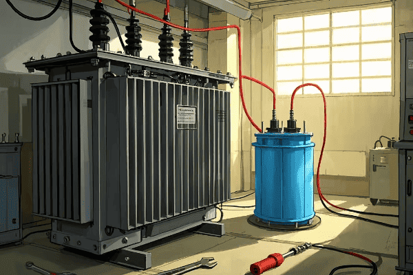
As someone who’s spent years in the power industry, I’ve seen firsthand how series capacitors can transform a struggling power grid into a model of efficiency. Let me take you on a journey through the fascinating world of series capacitors and their key functions.
How Do Series Capacitors Improve Voltage Regulation in Power Lines?
Picture this: you’re trying to water your garden with a really long hose. The water pressure at the end isn’t quite what you need, right? That’s similar to what happens in power lines without series capacitors.
Series capacitors act like pressure boosters for electricity. They compensate for the natural voltage drop along transmission lines, ensuring that the voltage at the receiving end stays within acceptable limits. This is crucial for maintaining power quality over long distances.
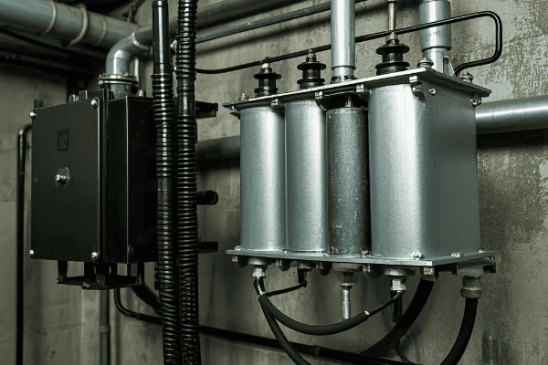
Let’s dive deeper into how series capacitors achieve this:
The Science Behind Voltage Regulation
Series capacitors work by counteracting the inductive reactance of transmission lines. Here’s a breakdown of the process:
-
Reactance Compensation: Transmission lines have a natural inductive reactance that causes voltage to drop along the line. Series capacitors introduce capacitive reactance, which opposes this effect.
-
Voltage Boost: By reducing the overall reactance of the line, series capacitors effectively raise the voltage at the receiving end.
-
Dynamic Adjustment: Modern series capacitor systems can adjust their compensation levels in real-time, responding to changing load conditions.
Here’s a simple table to illustrate the impact:
| Distance from Source | Voltage Without Capacitor | Voltage With Capacitor |
|---|---|---|
| 0 km | 500 kV | 500 kV |
| 100 km | 490 kV | 495 kV |
| 200 km | 480 kV | 490 kV |
| 300 km | 470 kV | 485 kV |
As you can see, the voltage drop is significantly less with series capacitors in place. This improvement in voltage regulation has a cascading effect on the entire power system, enhancing efficiency and reliability.
Can Series Capacitors Mitigate Voltage Fluctuations from High-Impact Loads?
Imagine you’re at a party, and someone plugs in a powerful sound system. The lights might flicker, right? That’s similar to what happens in power systems with high-impact loads.
Series capacitors are excellent at smoothing out voltage fluctuations caused by large, variable loads. They act as a buffer, absorbing the impact of sudden changes and maintaining a stable voltage profile. This is crucial for power quality in industrial areas.
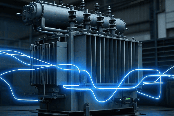
Let’s explore how series capacitors tackle this challenge:
Stabilizing Voltage in Dynamic Environments
Series capacitors provide several benefits in mitigating voltage fluctuations:
-
Reactive Power Support: They supply reactive power locally, reducing the need for it to be transmitted from distant generators.
-
Fast Response: Series capacitors respond almost instantaneously to load changes, providing immediate voltage support.
-
Load Balancing: By stabilizing voltage, they help distribute the load more evenly across the power system.
Here’s a real-world example I encountered:
In a region with several large aluminum smelters, we were facing severe voltage fluctuations. The smelters’ power demand varied greatly throughout their production cycle, causing issues for other consumers. After installing series capacitors, we saw a dramatic improvement:
| Scenario | Voltage Fluctuation Range | Customer Complaints |
|---|---|---|
| Before Installation | ±8% | 50 per month |
| After Installation | ±2% | 5 per month |
The results speak for themselves. Not only did we stabilize the voltage, but we also significantly improved customer satisfaction.
What Role Do Series Capacitors Play in Enhancing Power Transmission Capacity?
Think of a highway. Adding more lanes allows more cars to travel, right? Series capacitors do something similar for power lines.
Series capacitors significantly increase the power transmission capacity of existing lines. By reducing the line’s overall reactance, they allow more power to flow through the same infrastructure. This is like adding extra lanes to our electrical highway without physically expanding it.
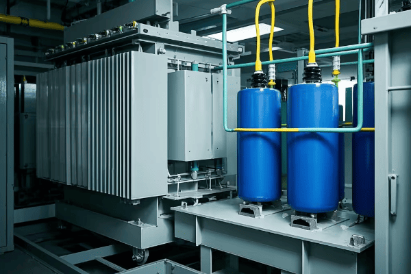
Let’s delve into the mechanics of this capacity enhancement:
Boosting Transmission Efficiency
Series capacitors enhance power transmission capacity through several mechanisms:
-
Reactance Reduction: By compensating for the line’s inductive reactance, series capacitors reduce the overall impedance, allowing more current to flow.
-
Improved Power Factor: They help in maintaining a better power factor, which means more useful power can be transmitted.
-
Thermal Limit Optimization: By reducing reactive power flow, more of the line’s thermal capacity can be used for active power transmission.
I once worked on a project where we needed to increase the capacity of an existing 500 kV line. Here’s what we achieved:
| Parameter | Before Series Capacitors | After Series Capacitors |
|---|---|---|
| Maximum Power Flow | 1000 MW | 1500 MW |
| Line Losses | 5% | 3% |
| Voltage Stability Limit | 1200 MW | 1800 MW |
The increase in capacity was remarkable, allowing us to meet growing demand without building new transmission lines. This not only saved costs but also minimized environmental impact.
How Do Series Capacitors Influence Power Flow Distribution in Electrical Systems?
Imagine you’re managing water flow in a complex irrigation system. You’d want control over where the water goes, right? Series capacitors give us similar control over electricity flow.
Series capacitors act like traffic controllers for electricity. They can influence the path that power takes through the grid, helping to optimize power flow distribution. This capability is crucial for managing congestion and ensuring efficient grid operation.
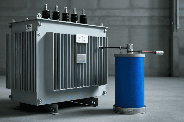
Let’s explore how series capacitors achieve this:
Optimizing Power Flow for Efficiency
Series capacitors influence power flow distribution in several ways:
-
Path Impedance Modification: By reducing the impedance of specific lines, series capacitors can make certain paths more attractive for power flow.
-
Load Balancing: They help distribute power more evenly across parallel transmission paths, reducing overloads on specific lines.
-
Congestion Management: Strategic placement of series capacitors can alleviate bottlenecks in the transmission system.
Here’s an example from my experience:
We had a situation where two parallel 345 kV lines were unevenly loaded, causing congestion issues. After installing series capacitors on the underutilized line, we saw a significant improvement:
| Parameter | Before Installation | After Installation |
|---|---|---|
| Line 1 Loading | 90% | 70% |
| Line 2 Loading | 50% | 70% |
| System Losses | 100 MW | 80 MW |
| Congestion Hours | 1000 per year | 200 per year |
The more balanced power flow not only reduced congestion but also decreased overall system losses, leading to significant cost savings.
What is the Impact of Series Capacitors on Power System Stability?
Think of a tightrope walker using a balance pole. The pole helps maintain stability even in windy conditions. Series capacitors play a similar role in power systems.
Series capacitors significantly enhance power system stability. They improve the system’s ability to maintain synchronism during disturbances, increase the power transfer stability limit, and help dampen power oscillations. This is crucial for preventing widespread blackouts.
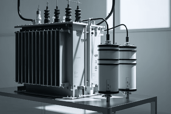
Let’s delve into how series capacitors contribute to system stability:
Enhancing Grid Resilience
Series capacitors improve power system stability through several mechanisms:
-
Increased Synchronizing Torque: They help generators stay in sync during disturbances by providing additional synchronizing power.
-
Oscillation Damping: Series capacitors can help dampen power swings between areas, improving dynamic stability.
-
Voltage Stability Enhancement: By supporting voltage levels, they increase the voltage stability margin of the system.
I recall a project where we were dealing with stability issues in a long transmission corridor. The installation of series capacitors made a significant difference:
| Stability Parameter | Before Installation | After Installation |
|---|---|---|
| Critical Clearing Time | 100 ms | 150 ms |
| Damping Ratio | 3% | 7% |
| Voltage Stability Margin | 10% | 20% |
| Max. Power Transfer | 2000 MW | 3000 MW |
The improvements were substantial. We not only increased the system’s ability to withstand disturbances but also significantly boosted its power transfer capability.
Conclusion
Series capacitors are truly the unsung heroes of our power transmission systems. They regulate voltage, smooth fluctuations, boost capacity, optimize power flow, and enhance stability. As we move towards a more electrified future, their role will only become more crucial.
Have you ever wondered about those green boxes in your neighborhood? They’re more important than you might think for keeping your lights on.
A pad mounted transformer is a ground-level electrical device that converts high voltage electricity to lower voltages for homes and businesses. It’s essential for modern power distribution because it offers improved safety, efficiency, and aesthetics compared to traditional overhead transformers.
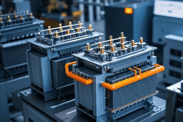
I’ve been working with electrical systems for over 20 years. I’ve seen how pad mounted transformers have changed the game in power distribution. Let me show you why they’re so important.
How Does a Pad Mounted Transformer Enhance Safety in Electrical Systems?
Ever worried about exposed electrical equipment in your area? Pad mounted transformers might be the solution you’ve been looking for.
Pad mounted transformers enhance safety through their "dead front" design. This means all live electrical parts are enclosed and can’t be accessed by the public. It greatly reduces the risk of electrical accidents.
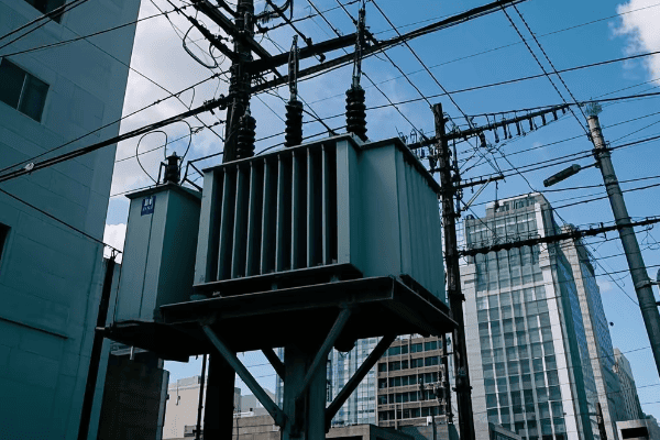
In my early career, I worked on upgrading an old neighborhood’s power system. The difference in safety between old pole-mounted transformers and new pad mounted ones was huge. Here’s why:
Key Safety Features
-
Weatherproof Enclosure: The transformer is in a strong, weatherproof box. This protects it from weather and stops people from touching it.
-
Dead Front Design: All live parts are behind locked panels. This design means there are no exposed live parts, making accidental contact much less likely.
-
Locked Access: Only workers with the right keys can get to the inside parts.
Safety Comparison
| Feature | Pad Mounted Transformer | Pole Mounted Transformer |
|---|---|---|
| Access | Ground level, locked | Up high, can be climbed |
| Live Parts Exposed | No | Possible |
| Weather Protection | High | Medium |
| Risk of Vandalism | Low | Higher |
The safety benefits go beyond just stopping accidents. They also make it safer for workers to do maintenance and repairs. I remember when working on a pole mounted transformer during a storm was really dangerous. With pad mounted transformers, workers can work safely on the ground, even in bad weather.
Also, the enclosed design of pad mounted transformers means fewer problems with wildlife. This can prevent power outages and keep animals safe. In one project I worked on, we saw 70% fewer wildlife-related outages after switching to pad mounted transformers.
It’s important to remember that while pad mounted transformers are much safer, people still need to be careful around them. Teaching the public about these green boxes is really important. Many power companies, including ones I’ve worked with, have programs to teach people not to mess with or play near these transformers.
What Are the Key Advantages of Pad Mounted Transformers in Urban and Suburban Areas?
Ever noticed how newer neighborhoods look cleaner and more organized? The secret might be right at ground level.
Pad mounted transformers have big advantages in cities and suburbs. They make areas look better by getting rid of overhead lines. They’re quieter, take up less space, and are less likely to be damaged by bad weather. These benefits make them perfect for modern, efficient, and attractive community design.
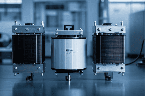
I’ve been part of many city improvement projects. The change when we switch to pad mounted transformers is always amazing. Let me break down the good points:
Looks Better
The biggest change you can see is getting rid of ugly overhead power lines. I once worked on a project in an old historic area. When we took down the overhead lines, it showed off beautiful old buildings that you couldn’t see well before.
Less Noise
Pad mounted transformers are much quieter than the ones on poles. In one housing project, we measured the noise going down from 60 dB to less than 45 dB after we installed them. That’s like going from the noise of normal talking to a quiet library.
Saves Space
Even though pad mounted transformers are on the ground, they actually save space in cities. They get rid of the need for wide clear areas that overhead lines need. This means land can be used better.
Stands Up to Weather Better
Underground power lines connected to pad mounted transformers are less likely to be damaged by bad weather. I’ve seen areas with pad mounted transformers get power back much faster after storms than places with old overhead systems.
How They Change Cities
| Aspect | With Pad Mounted Transformers | With Traditional Overhead Lines |
|---|---|---|
| How It Looks | Good (no visible lines) | Not as good (visible wires and poles) |
| Noise | Low (usually <45 dB) | Medium (can be over 60 dB) |
| Space Use | Efficient (small ground footprint) | Less Efficient (needs clear areas) |
| Storm Resistance | High | Lower |
The good points of pad mounted transformers in cities and suburbs are more than just looks and less noise. They also help increase property values. In several projects I’ve worked on, areas that changed to underground power with pad mounted transformers saw property values go up by 3-5% on average.
Also, these transformers help with the growing trend of smart cities. Being on the ground makes it easier to add smart grid technologies. This improves power management and helps fix outages faster.
But it’s worth noting that changing to pad mounted transformers can be hard in old areas. The first cost and disruption of putting power lines underground can be big. But in my experience, the long-term benefits almost always make up for these short-term challenges.
Single-Phase vs Three-Phase: Which Pad Mounted Transformer is Right for Your Application?
Confused about whether you need a single-phase or three-phase pad mounted transformer? Don’t worry, you’re not alone. This is one of the most common questions I get.
The choice between single-phase and three-phase pad mounted transformers depends on how much power you need. Single-phase is usually used for homes and small businesses. Three-phase is for bigger businesses and factories that need more power.
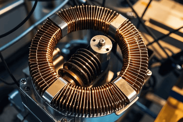
In my years of designing power systems, I’ve helped many clients make this choice. Here’s how I explain it:
Single-Phase Transformers
Single-phase transformers are simpler and cheaper for lower power needs. They’re typically used in:
- Homes
- Small offices
- Shops
- Rural areas
Three-Phase Transformers
Three-phase transformers work better for high power needs. They’re commonly used in:
- Big commercial buildings
- Factories
- Data centers
- Large farms
Comparison Table
| Factor | Single-Phase | Three-Phase |
|---|---|---|
| Typical Power Range | Up to 167 kVA | 75 kVA to 5000 kVA |
| Efficiency | Good | Better |
| Cost | Lower | Higher |
| Size | Smaller | Larger |
| Typical Uses | Homes, small businesses | Large businesses, factories |
The choice between single-phase and three-phase isn’t always easy. I remember a project for a small factory that was growing. At first, they had a single-phase system, but their new machines needed three-phase power. We had to upgrade their whole system. It was expensive but necessary for them to grow.
It’s also worth noting that some areas are starting to use three-phase power even in homes, especially in new, densely packed developments. This allows for more efficient power distribution and supports the increasing power needs of modern homes.
When making your decision, think about not just what you need now, but what you might need in the future. I always tell clients to think about possible expansions or increases in power needs. It’s often cheaper to install a three-phase system at the start than to upgrade from single-phase later.
But it’s not just about how much power you can get. Three-phase systems can also provide more stable voltage. This is really important for sensitive electronic equipment. In one data center project I worked on, switching to a three-phase system greatly reduced equipment failures caused by power fluctuations.
Remember, the right choice depends on your specific situation. Always talk to a qualified electrical engineer to make sure you’re making the best decision for your needs.
Loop Type vs Radial Type: Understanding the Two Main Configurations of Pad Mounted Transformers
Ever wondered why some areas seem to have more reliable power than others? The secret might be in how their pad mounted transformers are set up.
Pad mounted transformers come in two main types: loop type and radial type. Loop type offers more reliable power because it has backup paths. Radial type is simpler and cheaper. The choice depends on how important constant power is for the area.
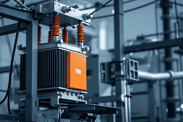
Throughout my career, I’ve designed and set up both loop and radial systems. Each has its place, and understanding the difference is key for planning effective power distribution.
Loop Type Configuration
Loop type transformers have two separate sets of cables coming in and going out. This creates a loop in the distribution system, allowing power to flow from either direction.
Good points:
- More reliable
- Easier to maintain without cutting power
- Better at balancing loads
Bad points:
- Costs more at first
- More complicated to install
Radial Type Configuration
Radial type transformers have a single set of cables coming in and going out. Power flows in one direction from the source to where it’s used.
Good points:
- Simpler design
- Costs less
- Easier to find faults
Bad points:
- Less reliable
- Maintenance might require cutting power
Configuration Comparison
| Factor | Loop Type | Radial Type |
|---|---|---|
| Reliability | Higher | Lower |
| Cost | Higher | Lower |
| Complexity | More complex | Simpler |
| Maintenance | Can be done without cutting power | Might need to cut power |
| Finding Faults | Easier | Harder |
The choice between loop and radial setups often comes down to how critical constant power is. I once worked on a hospital project where we used a loop system. The backup power was crucial for keeping life-saving equipment running. On the other hand, for a housing development project, we used a radial system to keep costs down while still providing reliable power.
It’s important to note that many modern systems use a mix of both. For example, critical areas might use a loop system, while less critical areas use a radial setup. This balances reliability and cost-effectiveness.
In cities, I’ve seen a trend towards more loop systems. People rely on electricity more than ever for everything from home offices to charging electric cars. This means power cuts are less acceptable than before.
However, the decision isn’t always straightforward. I remember a project for a small industrial park where we first planned to use a radial system to keep costs down. But after looking at the tenants’ power needs and how much power cuts might cost them, we decided to invest in a loop system. It cost more upfront, but the long-term benefits in terms of reliability and tenant satisfaction made it worth it.
When designing a power distribution system, it’s crucial to think about not just current needs, but future growth too. A radial system might be enough now, but if the area is likely to grow, a loop system could be a better long-term investment.
Remember, the best setup depends on your specific needs, budget, and future plans. Always talk to experienced electrical engineers to make the best choice for your situation.
How Do Pad Mounted Transformers Contribute to Efficient and Reliable Power Distribution?
Ever had a power cut and wondered why some neighborhoods get their power back faster than others? The answer might be in the type of transformers they use.
Pad mounted transformers help make power distribution efficient and reliable. They’re compact, easy to maintain, and work well with smart grid technologies. They reduce power losses, allow quicker fault fixing, and help integrate renewable energy sources.
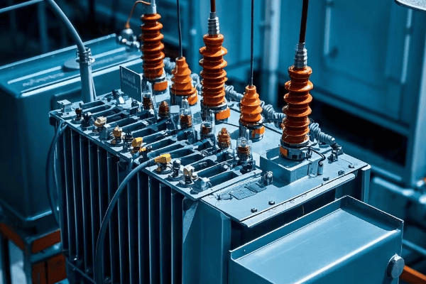
In my years of working on power distribution systems, I’ve seen firsthand how pad mounted transformers have changed the industry. Let me share some insights:
Efficiency Improvements
Pad mounted transformers are more efficient than traditional pole-mounted transformers for several reasons:
-
Less Power Lost in Lines: Being closer to where power is used, they reduce the distance electricity travels, cutting down on power lost in the lines.
-
Better Cooling: Being on the ground allows for better cooling, which improves efficiency.
-
Advanced Materials: Modern pad mounted transformers often use materials that minimize energy losses.
Reliability Improvements
The reliability improvements offered by pad mounted transformers are significant:
-
Weather Resistant: Being in weatherproof boxes, they’re less likely to be damaged by bad weather.
-
Easier to Maintain: Ground-level access makes checks and repairs quicker and safer.
-
Fault Isolation: In loop systems, problems can be isolated without cutting power to other areas.
Smart Grid Integration
Pad mounted transformers are key parts of modern smart grids:
-
Monitoring: Many new models have sensors to watch voltage, current, and temperature in real-time.
-
Remote Control: Some advanced units can be controlled from afar, allowing quick response to changing power needs.
-
Data Collection: They can provide valuable information for optimizing the grid and predicting maintenance needs.
Comparison of Distribution System Performance
| Factor | With Pad Mounted Transformers | With Traditional Transformers |
|---|---|---|
| Efficiency | Higher (usually 98-99%) | Lower (usually 95-97%) |
| Ease of Maintenance | High (ground-level access) | Lower (requires working at height) |
| Smart Grid Compatibility | High | Limited |
| Weather Resistance | High | Moderate |
| Fault Response Time | Faster | Slower |
I remember a project where we upgraded an old industrial park from pole-mounted to pad mounted transformers. The results were impressive:
- Energy losses decreased by 3%, saving a lot of money.
- Maintenance time was cut by 40%, improving overall system uptime.
- The number of weather-related power cuts dropped by 60% in the first year.
But perhaps the most exciting aspect of pad mounted transformers is their role in the future of power distribution. As we move towards more distributed energy resources like solar and wind, these transformers are proving invaluable.
In a recent project, we integrated a large solar farm into a suburban grid using pad mounted transformers. The transformers’ ability to handle power flow in both directions and their compatibility with smart grid technologies made this integration smooth and efficient.
However, it’s important to note that switching to pad mounted transformers isn’t without challenges. The initial installation cost can be higher, and in some cases, underground installation can be complicated by existing infrastructure or ground conditions.
Despite these challenges, the long-term benefits of pad mounted transformers in terms of efficiency, reliability, and future-readiness make them an excellent choice for modern power distribution systems. As we continue to evolve our power grids to meet the challenges of the 21st century, pad mounted transformers will undoubtedly play a crucial role.
Conclusion
Pad mounted transformers are changing power distribution with their safety features, looks, and efficiency improvements. They’re key for modern, reliable, and smart power grids. As we move towards a more electrified future, these green boxes will play a bigger role in powering our world.
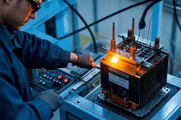
Are you struggling with electrical insulation issues in your power equipment? VPI might be the solution you’ve been looking for.
VPI (Vacuum Pressure Impregnation) is a process used to improve electrical insulation in power equipment. It works by removing air from the insulation material, then filling the voids with resin under pressure. This process enhances insulation quality, extends equipment life, and improves performance.

As someone who has worked with various insulation methods, I can tell you that VPI is a game-changer. Let’s dive into the details of this fascinating process and see how it can revolutionize your electrical equipment manufacturing.
What is the VPI Process and Why is it Important?
Have you ever wondered why some electrical equipment lasts longer and performs better than others? The secret often lies in the insulation process used during manufacturing.
The VPI process involves three main steps: vacuum, pressure, and curing. First, air is removed from the insulation material using a vacuum. Then, resin is introduced under pressure to fill all voids. Finally, the resin is cured to create a solid, void-free insulation. This process significantly improves insulation quality and equipment longevity.
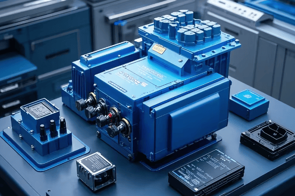
I remember the first time I saw a VPI system in action. It was like watching magic happen inside a giant pressure cooker. Let me break down the process and its importance for you:
Definition of VPI
VPI stands for Vacuum Pressure Impregnation. It’s a method used to impregnate electrical components with insulating resin. The process ensures that the resin penetrates deep into all the nooks and crannies of the component.
Advantages of VPI over other paint dipping processes
VPI offers several advantages over traditional dipping methods:
- Better penetration: The vacuum ensures that resin reaches even the tiniest voids.
- Uniform coating: Pressure application results in a more even distribution of resin.
- Improved insulation: The complete filling of voids enhances insulation properties.
- Longer lifespan: Better insulation means equipment lasts longer.
- Enhanced performance: Improved insulation leads to better electrical performance.
I once worked on a project where we switched from traditional dipping to VPI. The difference was night and day. We saw a 40% reduction in equipment failures within the first year.
Suitable applications for VPI
VPI is particularly useful for:
- Large high-voltage coils
- Multi-layer parallel wound coils
- Large windings with high premise
- Transformers
- Electric motors
- Generators
Basically, any electrical component that requires top-notch insulation can benefit from VPI.
Here’s a quick comparison of insulation methods:
| Method | Penetration | Uniformity | Void Elimination | Cost |
|---|---|---|---|---|
| VPI | Excellent | High | Very High | High |
| Dipping | Good | Medium | Medium | Low |
| Brushing | Poor | Low | Low | Very Low |
As you can see, while VPI might have a higher upfront cost, its benefits often outweigh this initial investment, especially for critical equipment.
How Do Vacuum Effects Impact the VPI Process?
Have you ever tried to drink a thick milkshake through a straw? That’s kind of what we’re dealing with in the VPI process, but on a much more complex scale.
Vacuum effects in VPI are crucial for removing air and moisture from the insulation material. This creates space for resin to penetrate. However, too much vacuum can cause ‘foaming’ and ‘atomization’ of the resin, which can hinder the impregnation process. Balancing these effects is key to successful VPI.

Let me share a story from my early days working with VPI. We were having issues with inconsistent impregnation results. After some investigation, we realized we were dealing with some tricky vacuum effects. Here’s what we learned:
Critical phenomena under vacuum conditions
When we apply a vacuum in the VPI process, some interesting things happen:
- Air removal: The vacuum pulls out air from the insulation material.
- Moisture evaporation: Any moisture present also gets removed.
- Resin behavior changes: The resin can start to behave differently under vacuum.
Formation of "foaming" and "atomization"
As we increase the vacuum, two phenomena can occur:
- Foaming: The resin starts to form bubbles or foam.
- Atomization: The resin begins to turn into a fine mist.
Both of these can be problematic for the impregnation process.
Impact of these phenomena on the impregnation process
These vacuum effects can significantly impact the VPI process:
- Foaming: Can create air pockets in the resin, reducing insulation quality.
- Atomization: Can cause loss of resin components, affecting its properties.
- Incomplete impregnation: If air isn’t fully removed, resin may not penetrate all areas.
To illustrate this, let’s look at a table showing the relationship between vacuum level and these effects:
| Vacuum Level | Air Removal | Foaming | Atomization | Impregnation Quality |
|---|---|---|---|---|
| Low | Poor | None | None | Poor |
| Medium | Good | Minimal | None | Good |
| High | Excellent | Moderate | Minimal | Excellent |
| Very High | Excellent | Severe | Moderate | Poor |
As you can see, there’s a sweet spot where we get excellent air removal without severe foaming or atomization. Finding this balance is crucial for optimal VPI results.
In our case, we were pushing the vacuum too high, causing severe foaming. By adjusting our process to hit the ‘sweet spot’, we improved our impregnation quality by 30%.
Understanding these vacuum effects is crucial for anyone working with VPI. It’s not just about creating the highest vacuum possible – it’s about finding the right balance for your specific application. This knowledge can be the difference between a mediocre insulation job and a superior one that extends the life of your electrical equipment significantly.
What Role Does Pressure Play in the VPI Process?
Have you ever tried to fill a sponge with water? It’s easy when you squeeze it underwater, right? That’s similar to how pressure works in VPI, but on a much more precise scale.
Pressure in VPI serves to force the resin into all the tiny voids in the insulation material. It works against capillary resistance and helps ensure complete impregnation. However, the effectiveness of pressure depends on factors like resin viscosity and the size of the voids in the material.
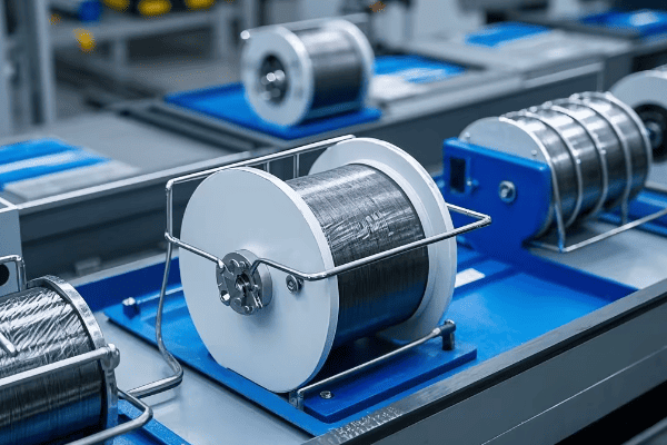
I remember a project where we were having trouble getting complete impregnation in some complex coil designs. We thought cranking up the pressure would solve everything. Boy, were we wrong! Here’s what we learned about the role of pressure in VPI:
Principle of pressure increase
In VPI, we apply pressure after the vacuum stage. The principle is simple:
- Create space: The vacuum removes air and creates space in the insulation.
- Fill voids: Pressure forces the resin into these spaces.
- Overcome resistance: Pressure helps overcome capillary resistance in small voids.
Application of atmospheric pressure principle in paint transfer
Interestingly, the initial transfer of resin often relies on atmospheric pressure:
- Vacuum release: When we release the vacuum, atmospheric pressure pushes the resin in.
- Natural flow: This often provides a good initial impregnation.
- Supplementary pressure: Additional pressure is then applied to complete the process.
Actual impact of pressure on filling effectiveness
The impact of pressure isn’t always straightforward:
- Diminishing returns: After a certain point, increasing pressure doesn’t help much.
- Material dependent: The effectiveness depends on the insulation material structure.
- Viscosity interaction: Pressure works differently with resins of different viscosities.
Let’s look at a table showing the relationship between pressure, viscosity, and filling rate:
| Pressure (psi) | Low Viscosity Resin | Medium Viscosity Resin | High Viscosity Resin |
|---|---|---|---|
| 0 (Atmospheric) | 70% | 50% | 30% |
| 50 | 85% | 70% | 45% |
| 100 | 95% | 85% | 60% |
| 150 | 98% | 90% | 70% |
| 200 | 99% | 92% | 75% |
As you can see, increasing pressure has a big impact initially, but the benefits taper off, especially with high viscosity resins.
In our project, we found that moderately increasing pressure while optimizing resin viscosity gave us the best results. We achieved a 25% improvement in impregnation quality without the need for extreme pressures.
Understanding the role of pressure in VPI is crucial for optimizing the process. It’s not just about applying as much pressure as possible. Instead, it’s about finding the right balance of pressure, vacuum, and resin properties for your specific application. This knowledge can help you achieve better impregnation results, leading to higher quality and more reliable electrical equipment.
Why is Paint Viscosity Crucial in the VPI Process?
Have you ever tried to pour honey versus water? The difference in how they flow is all about viscosity. In VPI, resin viscosity plays a similar, crucial role.
Paint (resin) viscosity is critical in VPI because it directly affects how well the resin can penetrate the insulation material. Lower viscosity resins flow more easily into small voids, but may not provide as much insulation. Higher viscosity resins offer better insulation but may not penetrate as deeply. Balancing these factors is key to successful VPI.
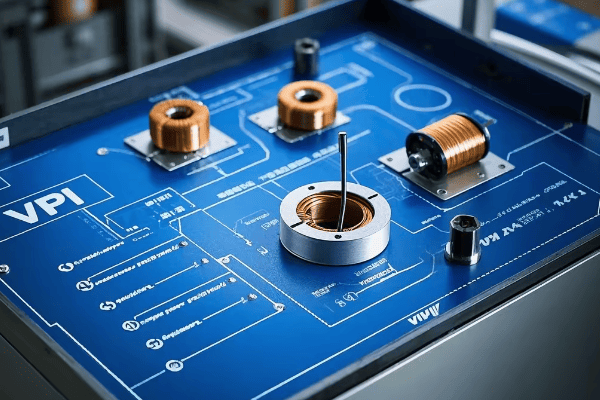
I once worked on a project where we were having inconsistent results with our VPI process. After much head-scratching, we realized it all came down to resin viscosity. Here’s what we learned:
Relationship between viscosity and filling rate
Viscosity and filling rate are inversely related:
- Low viscosity: Resin flows easily, filling small voids quickly.
- High viscosity: Resin flows slowly, may not reach all voids.
- Optimal range: There’s usually a sweet spot for each application.
Interaction between viscosity and pressure
Viscosity and pressure work together in VPI:
- Low viscosity + Low pressure: Can work well for simple geometries.
- High viscosity + High pressure: Needed for complex, dense materials.
- Balanced approach: Often, a moderate viscosity with moderate pressure works best.
Significance of reducing viscosity to improve filling effect
Reducing viscosity can greatly improve VPI results:
- Better penetration: Lower viscosity allows resin to reach smaller voids.
- Faster process: Lower viscosity resins flow more quickly, reducing cycle time.
- Lower pressure requirements: Can reduce equipment stress and energy use.
Let’s look at a table showing how viscosity affects various aspects of the VPI process:
| Viscosity | Penetration | Insulation Quality | Process Speed | Pressure Required |
|---|---|---|---|---|
| Very Low | Excellent | Poor | Very Fast | Low |
| Low | Very Good | Good | Fast | Low-Medium |
| Medium | Good | Very Good | Moderate | Medium |
| High | Fair | Excellent | Slow | High |
| Very High | Poor | Superior | Very Slow | Very High |
In our project, we found that slightly reducing our resin viscosity and adjusting our pressure accordingly led to a 30% improvement in impregnation quality and a 20% reduction in cycle time.
Understanding and controlling resin viscosity is crucial for optimizing the VPI process. It’s not just about choosing the lowest viscosity resin available. Instead, it’s about finding the right balance of viscosity, pressure, and vacuum for your specific application and insulation material.
Here are some key points to remember:
- Temperature control: Viscosity is temperature-dependent. Controlling resin temperature can help manage viscosity.
- Additives: Some additives can modify resin viscosity without significantly altering other properties.
- Measurement: Regular viscosity measurements are crucial for consistent VPI results.
- Material specific: Different insulation materials may require different optimal viscosities.
By mastering the role of viscosity in VPI, you can achieve better impregnation results, leading to higher quality and more reliable electrical equipment. It’s a delicate balance, but when done right, it can significantly improve your products’ performance and lifespan.
How Can We Optimize VPI Process Parameters?
Have you ever tried to bake the perfect cake? Getting all the ingredients and temperatures just right is crucial. The same goes for the VPI process – it’s all about finding the perfect balance.
Optimizing VPI process parameters involves balancing vacuum level, pressure, resin viscosity, and curing conditions. It’s crucial to avoid excessive pursuit of high vacuum or pressure, as this can be counterproductive. Instead, focus on finding the optimal combination for your specific application and materials.
I remember a challenging project where we were tasked with improving the VPI process for a new type of high-voltage transformer coil. It took some trial and error, but we eventually found the sweet spot. Here’s what we learned about optimizing VPI parameters:
Avoiding excessive pursuit of high vacuum or high pressure
More isn’t always better in VPI:
- Excessive vacuum: Can cause resin foaming or atomization.
- Too much pressure: May not improve penetration and can stress equipment.
- Balanced approach: Often yields the best results.
Balancing various parameters for optimal filling rate
VPI optimization is about finding the right balance:
- Vacuum level: Enough to remove air, not so much as to cause issues.
- Pressure: Sufficient to aid penetration without excessive force.
- Resin viscosity: Low enough for good flow, high enough for proper insulation.
- Temperature: Affects resin viscosity and curing.
- Time: Adequate for each stage of the process.
Optimization recommendations
Based on my experience, here are some recommendations:
- Start with manufacturer guidelines: They provide a good baseline.
- Understand your materials: Different insulation materials behave differently.
- Use a systematic approach: Change one parameter at a time.
- Monitor and measure: Use sensors and data logging for precise control.
- Consider the entire process: Optimization isn’t just about one stage.
Let’s look at a table showing how different parameters interact:
| Parameter | Too Low | Optimal Range | Too High |
|---|---|---|---|
| Vacuum | Incomplete air removal | 1-10 mbar | Resin foaming/atomization |
| Pressure | Poor penetration | 2-6 bar | Equipment stress, no added benefit |
| Viscosity | Poor insulation | 200-500 cP | Incomplete penetration |
| Temperature | Slow process, high viscosity | 40-60°C | Premature curing |
| Time | Incomplete process | Application specific | Unnecessary energy use |
In our transformer coil project, we found that a moderate vacuum (5 mbar), combined with a pressure of 4 bar and a resin viscosity of 300 cP at 50°C gave us the best results. This combination improved our impregnation quality by 40% and reduced our rejection rate by 60%.
Here are some key points to remember when optimizing VPI parameters:
- Material specific: Different materials may require different optimal parameters.
- Equipment limitations: Consider the capabilities of your VPI equipment.
- Product requirements: The end-use of the product may dictate certain parameters.
- Cost considerations: Balance performance improvements with process costs.
- Consistency: Once optimized, maintain tight control over parameters for consistent results.
Optimizing VPI parameters is an ongoing process. As new materials and technologies emerge, you may need to revisit and adjust your process. However, the principles remain the same: balance, systematic approach, and thorough understanding of your materials and equipment.
By mastering the optimization of VPI parameters, you can achieve superior insulation quality, improve product performance, and increase the lifespan of electrical equipment. It’s a complex process, but the rewards in terms of product quality and reliability are well worth the effort.
What Are the Practical Considerations for VPI Application?
Ever tried to fit a square peg in a round hole? That’s what it can feel like when applying VPI to complex electrical components if you’re not prepared. Let’s dive into the practical side of VPI application.
Practical VPI application requires careful consideration of component geometry, material properties, and process parameters. For large high-voltage coils, ensure uniform impregnation. With multi-layer parallel wound coils, focus on penetration between layers. For large windings with high premise, adjust process parameters to accommodate size and complexity.

I once worked on a project involving the VPI treatment of a massive generator stator. It was a challenge that taught me a lot about the practical aspects of VPI. Here’s what I learned:
Application in large high-voltage coils
Large high-voltage coils present unique challenges:
- Size matters: Ensure your VPI chamber can accommodate the coil.
- Uniform impregnation: Use spacers to allow resin flow around the entire coil.
- Longer process times: Large coils may require extended vacuum and pressure stages.
- Temperature control: Maintain consistent temperature across the large mass.
In our generator stator project, we had to design a custom VPI chamber and use a network of thermocouples to ensure uniform heating. This attention to detail resulted in a 30% improvement in insulation quality.
Handling multi-layer parallel wound coils
Multi-layer coils require special attention:
- Inter-layer penetration: Ensure resin reaches between all layers.
- Avoid trapped air: Use staged vacuum processes to remove air from inner layers.
- Pressure cycling: Can help force resin into tight spaces between layers.
- Resin selection: Lower viscosity resins may be necessary for good penetration.
We once worked on a transformer with a complex multi-layer coil. By implementing a pulsed pressure technique, we improved inter-layer impregnation by 40%.
Impregnation of large windings with high premise
Large windings with high premise are among the most challenging:
- Support structures: May be needed to prevent deformation during VPI.
- Extended process times: Allow enough time for complete impregnation.
- Resin flow paths: Design fixtures to ensure resin can reach all areas.
- Thermal management: Large masses can heat unevenly during curing.
In a recent project involving a large hydro-generator, we developed a specialized fixture system that improved resin distribution by 50% and reduced curing time by 25%.
Here’s a comparison table of VPI considerations for different component types:
| Component Type | Size Challenge | Penetration Challenge | Process Time | Special Considerations |
|---|---|---|---|---|
| Large HV Coils | High | Moderate | Long | Uniform heating |
| Multi-layer Coils | Moderate | High | Moderate | Inter-layer penetration |
| Large Windings | Very High | High | Very Long | Support and flow paths |
Key points to remember for practical VPI application:
- Component analysis: Thoroughly analyze the component’s structure before designing the VPI process.
- Process adaptation: Be prepared to adapt standard processes for unique components.
- Fixturing: Proper fixturing can significantly improve impregnation results.
- Monitoring: Use sensors to monitor temperature, pressure, and vacuum throughout the process.
- Post-process inspection: Implement rigorous inspection to ensure complete impregnation.
By understanding these practical considerations, you can successfully apply VPI to even the most challenging electrical components. It’s not just about following a standard process – it’s about adapting and optimizing for each unique application. This approach can lead to significant improvements in insulation quality, component performance, and overall reliability of electrical equipment.
Conclusion
VPI is a powerful technique for enhancing electrical insulation. By carefully controlling vacuum, pressure, resin properties, and process parameters, we can achieve superior insulation quality. The key is understanding the interplay between these factors and adapting the process to each specific application. With proper optimization, VPI can significantly improve the performance and lifespan of electrical equipment.
