The Solar Transformer Guide: Unlocking the Technical Core from PV Array to Grid
Introduction
Transformers that don’t match, run hot, or change the quality of the power make PV plants work less well. If not fixed, losses, trips, and fines will happen. A solar transformer separates1, boosts, and controls the output of an inverter so that solar energy can safely and efficiently connect to the grid.
The “Heart” of the PV System: The Main Job and Technical Problems of Solar Transformers
PV sites have to deal with limited space, changing output, and rigorous constraints about how to connect to other systems. Not paying attention to these causes problems and failures. Solar transformers made for this purpose create a safe, compliant connection between string/central inverters and the utility network, managing voltage and harmonics where they are most important.
What is a Solar Transformer? The Important Part It Plays in the Photovoltaic System
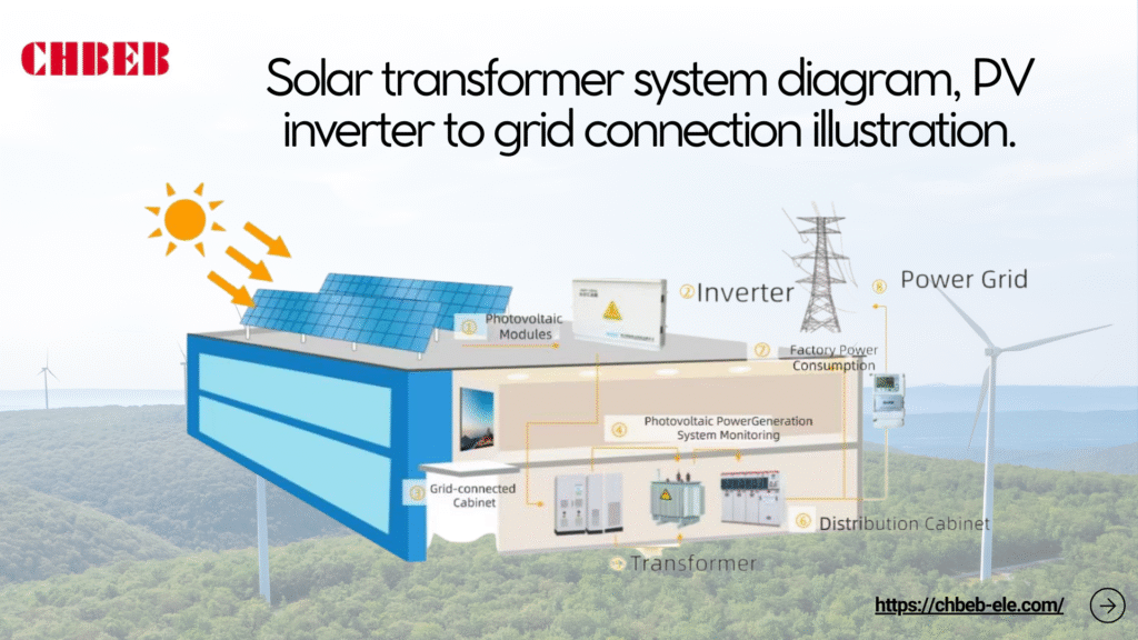
The solar transformer is the electrical “heart” that changes the output of a low-voltage inverter into medium-voltage levels for collection or export. It does this while making sure that everything is safe, works with other devices, and is reliable. It does more than just modify the voltage; it also has functions that are specific to how PV works:
- Galvanic isolation: This keeps the inverter circuits separate from the utility, which makes it possible to safely find and fix faults.
- Step-up conversion: This raises the normal outputs of inverters (about 400–1000 VAC) to MV feeders (about 11–35 kV) so that they can be sent more efficiently within the plant and to the grid.
- Vector group and zero-sequence control: Delta and star selections stop triplen harmonics, control neutral currents, and help with grounding schemes.
- DC bias tolerance: This stops leftover DC from inverters from causing core saturation and overheating.
- Impedance tuning: Changes the shape of fault currents and voltage regulation, keeping the collecting system stable during ramps and failures.
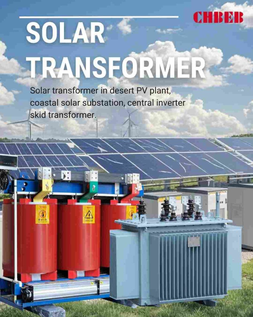
- Environmental resilience: Outdoor-rated enclosures, protection against corrosion, and classes for temperature rise that work in deserts, on the shore, or in the mountains.
- Integration: MV switchgear, protection, and metering are all in the same place in skid or power-station designs, which makes them easier to set up.
A Closer Look at the Two Technical Problems of Voltage and Harmonics
The output of the PV changes and has switching artifacts. If not handled, voltage swings and harmonics can lower yield and break grid codes. Solar transformers deal with both of them by making choices about taps, impedance, vector group, and thermal margins.
- Managing voltage: The inverter AC goes up and down with the amount of sunlight and the temperature. Set the right tap ranges (like ±2×2.5%) to keep the MV at the point of connections. OLTC isn’t prevalent in PV, but it can make sense for long feeders or weak grids.
- Ride-through and regulation: Make sure that the transformer’s impedance can handle low- and high-voltage ride-through without too much voltage drop when power ramps up quickly.
- Risk of DC injection: Even little DC parts can make the core flux reach saturation. Set DC tolerance and monitoring; make sure that the inverter’s DC-injection restrictions are followed.
- Harmonic control2: Multilevel switching lowers THD, although high-frequency parts increase stray losses. Use the shape of the winding, the shielding, and the location of the core and winding to keep the heating to a minimum.
- Vector group strategy: A delta on the inverter side can catch triplen harmonics and smooth out the currents that the MV system sees. A star on the MV side gives neutral/earthing where needed.
- To avoid resonance, think about cable capacitance and how filters interact with each other. Choose %Z and layout to keep amplification away from switching frequencies.
- PWM ripple can cause audible noise, which is called acoustic noise. Low-noise designs, clamping, and controlling flux density help keep complaints down near communities.
Practical Application: Choosing, Designing, and Future Trends
Bad ratings, bad cooling, or old specs waste money and energy. That hurts LCOE and compliance over time. Use a strict selection procedure and up-to-date monitoring to make sure you design things well now and are ready for what tomorrow will bring.
How to Pick the Best Solar Transformer: Important Factors and Design Issues
Make the specification based on measured demand, environmental stresses, and grid rules. Then check the thermal and electrical margins for PV’s heavy-duty ramp. Check out the list below.
- Power rating (kVA/MVA): The size of the inverter should be enough to handle the peak AC power and any growth or dirt that may occur.
- Primary and secondary voltages: Make sure that the inverter AC (for example, 480/690/800–1000 V) matches the collection/export MV (for example, 11/22/33 kV) and utility standards.
- Impedance (%Z)3: Set restrictions on the fault current, keep the voltage steady, and let several transformers work together on the same bus.
- Vector group: Dyn or Ynd variations are common alternatives for PV. Check with the utility to make sure the neutral and grounding approach is correct.
- Losses and efficiency: Look at the no-load/load losses over the predicted dispatch profile. Low losses lower the lifetime energy cost and heat.
- Cooling and insulation: ONAN/ONAF for most outdoor work; for greater fire point and sustainability, think about natural ester fluids, or dry-type fluids where liquids are not allowed.
- Thermal class and ambient: Give the temperature rise and the ambient temperature (for example, 40–50 °C in the desert) as well as the altitude derating. If necessary, include forced-air stages.
- DC tolerance and harmonics: Set limits for DC bias, K-factor, or an equivalent thermal allowance, and devise ways to deal with high-frequency ripple.
- Taps and regulation: Off-circuit taps are common. Only use OLTC if the greater complexity and maintenance are worth the extra voltage control value.
- Environment and corrosion: Coatings for C4/C5-M maritime and industrial environments, animal guards, sand shields, and IP/ingress protection that fit the site.
- Monitoring and protection: oil level and temperature (or winding RTDs), pressure relief, quick pressure rise, moisture indicators, and bushing or partial-discharge options.
- Standards and testing: Follow the IEC4/IEEE rules that apply; ask for routine test reports and, for important units, type/special tests.
| PV Scenario | Design Focus | Why It Matters |
|---|---|---|
| String inverters on long MV feeders | Higher %Z, wider taps, low-loss core | Stabilizes voltage along feeders; reduces feeder losses. |
| Central inverter block near substation | Compact footprint, high thermal margin | Handles concentrated heat; eases layout and maintenance. |
| Weak grid interconnection | Careful impedance, OLTC evaluation, robust vector group | Improves ride-through and voltage compliance under disturbances. |
| Desert/coastal environment | C5-M coatings, sand/salt ingress control, ester fluids | Extends service life, enhances fire safety and sustainability. |
| Hybrid PV + storage (bidirectional) | Bi-directional thermal design, dc-bias limits, monitoring | Supports charge/discharge cycling without overheating or saturation. |
How Solar Transformer Technology Has Changed Over Time to Make Your System Future-Proof
PV systems are scaling and digitizing. Designs that fit today may constrain tomorrow’s output or compliance. Build with headroom and adopt technologies that track where PV is going, not where it was.
- Higher DC bus and inverter power: 1500 Vdc arrays and higher-power blocks push transformer currents and thermal design. This means that there are large temperature rise margins and staged cooling.
- Materials and fluids: Amorphous cores reduce no-load losses. Natural esters enhance the fire point and biodegradability while also making the material more resistant to moisture.
- Digital monitoring: Online indications for temperature, humidity, and dissolved gas (where they apply) make it possible to plan maintenance ahead of time and cut down on downtime.
- Designing for good power quality: Advanced winding and shielding shapes cut down on stray losses caused by inverter switching. Vector groups are tailored to reduce harmonics.
- Hybrid and grid-forming readiness: Storage and grid-support functions add bidirectional flows and new fault characteristics; make sure that thermal and dielectric symmetry is maintained.
- Control of EMI and sound: Low-noise laminations, better clamping, and EMI shielding keep neighboring communities and sensitive equipment safe.
- Harsh-site packaging: IP ratings that are higher, sealed bushings, barriers for wildlife, and corrosion systems that are meant to last for decades, not just seasons.
- Modular power stations: Factory-installed transformer and MV switchgear skids cut down on schedules, make quality more consistent, and make O&M easier.
Conclusion
Solar transformers are not just ordinary transformers placed in PV plants — they are purpose-built to bridge the gap between the low-voltage output of inverters and the medium/high-voltage levels required by the utility grid.
Unlike conventional distribution transformers that step voltage down for end users, a solar transformer primarily works as a step-up device: it boosts a few hundred volts from PV inverters to 11 kV, 22 kV, or 33 kV for safe, efficient interconnection.
Why step-up is essential
- Reduces current for a given power level.
- Minimizes I2R line losses and cable heating.
- Enables reliable collection and delivery over distance to the grid POI.
PV-specific challenges a solar transformer must handle
- Voltage fluctuation: rapid ramps with irradiance and temperature.
- Harmonics & high-frequency ripple: from inverter PWM switching.
- DC injection risk: preventing core saturation and protection trips.
- Harsh environments: desert heat, coastal corrosion, wildlife ingress.
Design responses that ensure safety & cost control
- Appropriate impedance (%Z) and tap ranges for voltage stability and ride-through.
- Optimized vector group (e.g., Dyn/Ynd) for triplen-harmonic trapping and grounding strategy.
- Winding/core geometry and shielding to limit stray losses and acoustic noise.
- Thermal headroom with ONAN/ONAF cooling; options for natural esters or dry-type where required.
- Monitoring (winding/oil temperature, pressure relief, moisture/PD options) to reduce unplanned outages.
In short: choosing the right solar transformer is not just about “making the connection.” It is about ensuring stable transmission, reducing losses, protecting equipment, and aligning technology, safety, and environment with your project’s future growth.
- Solar inverter — Wikipedia ↩︎
- Harmonics in Power Systems — IEEE Xplore ↩︎
- Transformer Impedance and Fault Current — ScienceDirect ↩︎
- IEC Transformer Standards — IEC ↩︎
Learn More
Want to explore more transformer solutions? Download our latest product catalog or browse our product categories to find the right solution for your project.
