Are you confused about how electricity gets safely into your home? You’re not alone. Many homeowners are unaware of the crucial role residential transformers play in powering our daily lives. But what exactly are these devices, and why are they so important for your home’s electrical system?
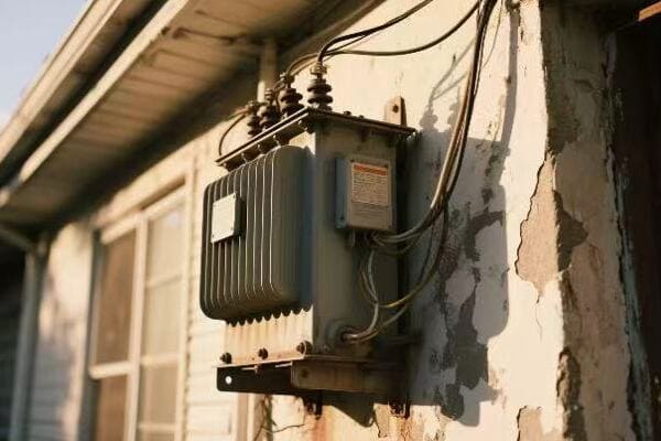
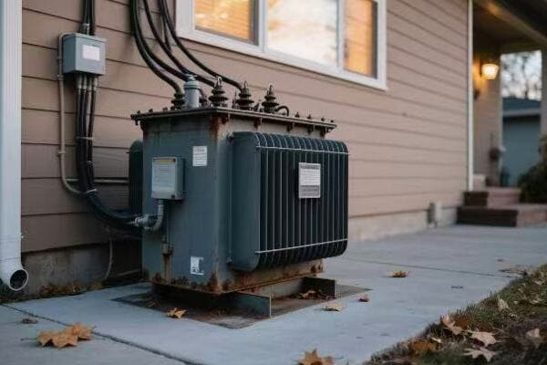
A residential transformer is a compact power device that steps down high-voltage electricity from utility lines to usable levels (120/240V) for household appliances. It ensures safe, reliable power for homes and is commonly pole-mounted or pad-mounted in suburban and urban areas.
In this comprehensive guide, I’ll walk you through everything you need to know about residential transformers. Whether you’re a homeowner curious about your electrical system or a professional looking to expand your knowledge, this article will provide valuable insights into these essential devices that power our homes.
What Is a Residential Transformer?
Have you ever wondered how the high-voltage electricity from power lines becomes safe to use in your home? This is where residential transformers come in. But what exactly are these devices, and why are they so crucial for your home’s electrical system?
Residential transformers are distribution-level electrical devices designed to convert high-voltage power from utility grids into lower voltages suitable for household use. They play a crucial role in delivering stable energy for lighting, appliances, and HVAC systems. These transformers are the vital link between the power grid and your home’s electrical system.

Understanding Residential Transformers
Let’s break down the key aspects of residential transformers:
- Purpose and Function
- Basic Components
- Voltage Transformation
- Location and Installation
- Safety Features
Purpose and Function
Residential transformers serve a critical role:
- Step down high voltage (typically 7.2kV to 14.4kV) to usable household voltage (120/240V)
- Provide a safe interface between utility power and home electrical systems
- Ensure stable power supply for all household electrical needs
I once visited a newly developed suburban area where the installation of residential transformers was underway. It was fascinating to see how these compact devices were the key to powering entire neighborhoods.
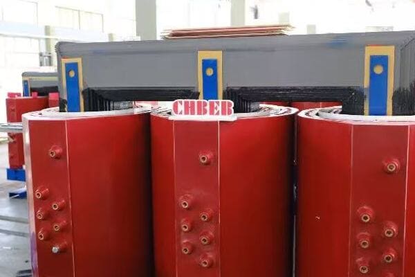
Basic Components
A typical residential transformer consists of:
- Primary winding (connected to high-voltage lines)
- Secondary winding (connected to household circuits)
- Core (usually made of laminated steel)
- Insulating material (oil or dry-type)
- Protective casing
During a recent home renovation project, I had the opportunity to examine a pad-mounted transformer up close. The compact design and robust construction were impressive, considering the critical function it serves.
Voltage Transformation
The transformation process is based on electromagnetic induction:
- High voltage in the primary winding creates a magnetic field
- This field induces a lower voltage in the secondary winding
- The ratio of primary to secondary windings determines the voltage step-down
Here’s a simple breakdown of voltage transformation:
| Input (Primary) Voltage | Output (Secondary) Voltage | Typical Application |
|---|---|---|
| 7,200V | 120/240V | Single-family homes |
| 14,400V | 120/240V | Larger residential areas |
| 4,800V | 120/208V | Multi-unit dwellings |
Location and Installation
Residential transformers are strategically placed:
- Pole-mounted: Common in older neighborhoods and rural areas
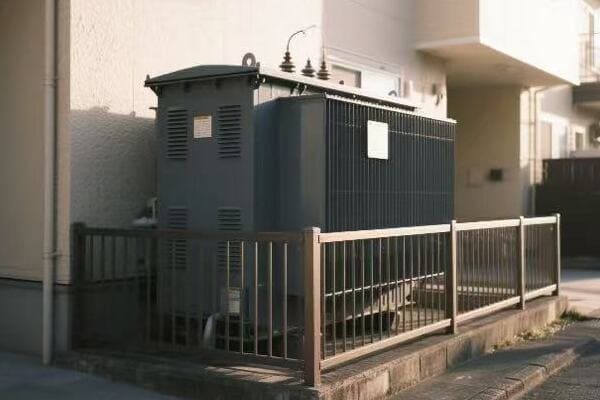
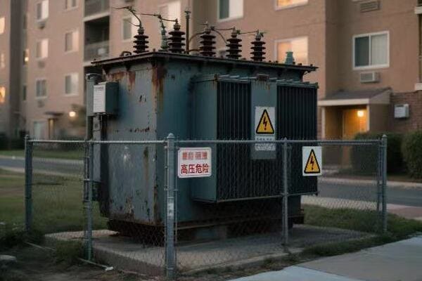
- Pad-mounted: Prevalent in newer developments and underground power systems
- Sometimes installed in basements or on roofs in urban high-rises
Safety Features
Modern residential transformers include various safety features:
- Overload protection
- Short-circuit protection
- Thermal monitoring
- Weatherproof enclosures for outdoor units
Key points to remember about residential transformers:
- They are the crucial link between high-voltage power lines and your home’s electrical system
- Transformers step down voltage to safe, usable levels for household appliances
- They come in various types suitable for different residential settings
- Safety features are integral to their design and function
- Proper installation and maintenance are crucial for reliable home power supply
In my experience, understanding the basics of residential transformers can be incredibly useful for homeowners. I’ve seen cases where this knowledge helped residents communicate more effectively with electricians and utility companies during power issues or home renovations.
As we move forward to discuss how these transformers work, keep in mind the critical role they play in safely delivering power to your home. Their function, though often overlooked, is fundamental to our modern, electricity-dependent lifestyles.
How Residential Transformers Work?
Are you curious about the inner workings of the device that safely brings electricity into your home? Understanding how residential transformers function can seem complex, but it’s fascinating once you grasp the basics. So, how exactly do these crucial devices transform dangerous high-voltage electricity into the safe, usable power that runs your household appliances?
Residential transformers work on the principle of electromagnetic induction. They use two coils of wire – primary and secondary – wound around an iron core. When alternating current flows through the primary coil, it creates a changing magnetic field. This field induces a voltage in the secondary coil, which is then distributed to homes at a lower, safer voltage level.
The Inner Workings of Residential Transformers
Let’s break down the operation of residential transformers:
- Electromagnetic Induction Principle
- Core and Windings
- Voltage Step-Down Process
- Insulation and Cooling
- Load Management and Efficiency
Electromagnetic Induction Principle
The fundamental principle behind transformer operation:
- Alternating current in the primary winding creates a changing magnetic field
- This changing field induces voltage in the secondary winding
- The number of turns in each winding determines the voltage ratio
I once explained this concept to a curious homeowner using a simple demonstration with two coils and a magnet. Moving the magnet through one coil induced a small current in the other, illustrating the basic principle of how transformers work.
Core and Windings
The physical components that make induction possible:
- Core: Usually made of laminated steel to reduce energy losses
- Primary winding: Connected to the high-voltage power line
- Secondary winding: Delivers lower voltage to residential circuits
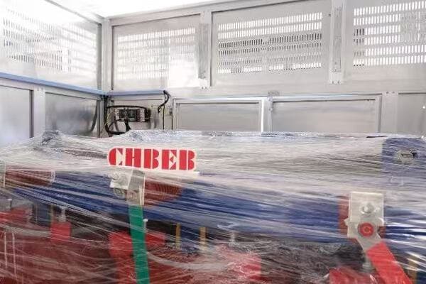
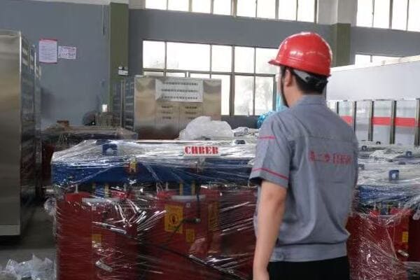
During a recent factory tour, I observed the precision involved in winding transformers. The careful layering of windings and core assembly is crucial for efficient operation.
Voltage Step-Down Process
How the voltage is actually reduced:
- Input voltage (e.g., 7,200V) enters the primary winding
- Magnetic field induces voltage in the secondary winding
- Fewer turns in the secondary winding result in lower output voltage (e.g., 240V)
Here’s a simplified example of the step-down process:
| Primary Winding | Secondary Winding | Input Voltage | Output Voltage |
|---|---|---|---|
| 1000 turns | 33 turns | 7,200V | 240V |
Insulation and Cooling
Crucial for safe and efficient operation:
- Oil-immersed: Uses mineral oil for insulation and cooling
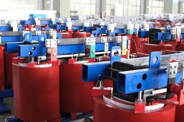
- Dry-type: Uses air or solid materials for insulation
I recall a project where we opted for a dry-type transformer in a residential high-rise due to fire safety concerns. The absence of oil made it a safer choice for indoor installation.
Load Management and Efficiency
Transformers must handle varying loads efficiently:
- Designed to operate optimally at average household demand
- Can handle short-term overloads (e.g., during peak usage times)
- Energy efficiency is crucial to minimize losses
Key points to understand about transformer operation:
- The principle of electromagnetic induction is fundamental to transformer function
- The ratio of turns in primary and secondary windings determines voltage step-down
- Proper insulation and cooling are essential for safe, efficient operation
- Transformers are designed to handle varying loads throughout the day
- Energy efficiency in transformers directly impacts household electricity costs
In my experience, grasping these operational principles helps homeowners appreciate the complexity behind their seemingly simple power supply. I’ve seen this understanding lead to more informed decisions about home electrical systems and energy usage.
For instance, during an energy efficiency consultation, explaining how transformer losses affect overall power consumption helped a homeowner understand the importance of using energy-efficient appliances to reduce the load on their local transformer.
As we move on to discuss common types of residential transformers, keep in mind how these operational principles apply to different designs and installations. Understanding the basics of how transformers work sets the foundation for appreciating the various types used in residential settings.
Common Types of Residential Transformers?
Are you aware of the different types of transformers that might be powering your home? The variety of residential transformers can be confusing, but understanding these types is crucial for homeowners and professionals alike. So, what are the common types of residential transformers, and how do they differ in their applications?
Common types of residential transformers include pole-mounted, pad-mounted, and compact substation units. Pole-mounted transformers are typically used in rural or suburban areas, pad-mounted transformers are popular in underground cable systems in urban neighborhoods, and compact substation units are often used in gated communities or apartment complexes. Each type is selected based on factors like grid layout, safety, noise, and maintenance accessibility.
Exploring Residential Transformer Types
Let’s examine the main types of residential transformers:
- Pole-Mounted Transformers
- Pad-Mounted Transformers
- Compact Substation Units
- Specialized Residential Transformers
- Factors Influencing Transformer Selection
Pole-Mounted Transformers
These are the most common in many areas:
- Mounted on utility poles, typically seen in older neighborhoods and rural areas
- Compact design, usually cylindrical
- Easily accessible for maintenance, but exposed to weather elements
I recently worked on a project in a suburban area where pole-mounted transformers were the preferred choice. Their elevated position provided protection from flooding and vandalism, which were concerns in that particular location.
Pad-Mounted Transformers
Increasingly popular in newer developments:
- Installed on concrete pads at ground level
- Enclosed in metal cabinets for safety and aesthetics
- Ideal for areas with underground power distribution
During a recent residential development project, we opted for pad-mounted transformers. Their low profile and ability to blend with landscaping made them an attractive option for the homeowners’ association.
Compact Substation Units
Used in larger residential complexes:
- Combine transformer and switchgear in one unit
- Suitable for apartment buildings or gated communities
- Offer more power capacity and control options
Here’s a comparison of these common transformer types:
| Type | Typical Location | Advantages | Considerations |
|---|---|---|---|
| Pole-Mounted | Rural, suburban areas | Easy maintenance, less ground space | Exposed to elements |
| Pad-Mounted | Urban, new developments | Aesthetically pleasing, protected | Requires ground space |
| Compact Substation | Large residential complexes | Higher capacity, more control | Larger footprint, higher cost |
Specialized Residential Transformers
Some unique situations require specialized transformers:
- Underground vault transformers for dense urban areas
- Submersible transformers for flood-prone regions
- Low-noise transformers for noise-sensitive areas
I once worked on a project in a flood-prone coastal area where we used specially designed submersible transformers. These units could continue operating even when temporarily submerged, ensuring power reliability during severe weather events.
Factors Influencing Transformer Selection
Several factors determine the choice of transformer:
- Local utility standards and preferences
- Environmental conditions (climate, flood risk, etc.)
- Aesthetic considerations of the neighborhood
- Maintenance accessibility
- Future growth and power demand projections
Key considerations when dealing with residential transformer types:
- Understand the specific needs and constraints of the residential area
- Consider long-term maintenance and replacement accessibility
- Factor in environmental conditions and potential hazards
- Balance aesthetics with functionality, especially in residential areas
- Consider future power needs and potential for area growth
In my experience, the choice of transformer type can significantly impact both the reliability of power supply and the overall aesthetics of a residential area. I’ve seen cases where the wrong choice led to maintenance difficulties or community dissatisfaction.
For example, in a recent urban renewal project, switching from older pole-mounted transformers to modern pad-mounted units not only improved the visual appeal of the neighborhood but also enhanced safety and reliability by moving the transformers away from overhead lines and potential vehicle collisions.
As we move forward to discuss the differences between residential and commercial transformers, keep in mind how these various types of residential transformers cater to different needs and environments. Understanding these differences is crucial for making informed decisions in electrical system planning and upgrades.
Residential vs Commercial Transformers: What’s the Difference?
Are you confused about how residential transformers differ from their commercial counterparts? This distinction is crucial for proper electrical system planning and installation. But what exactly sets these two types of transformers apart, and why does it matter for your project?
Residential transformers typically handle lower voltages (120/240V) and smaller loads compared to commercial transformers, which often deal with higher voltages (208V, 480V, or 600V) and larger power demands. Residential units are designed for homes and small apartments, while commercial transformers serve offices, factories, and malls. Size, capacity, and design features also differ to meet the specific needs of residential versus commercial applications.
Key Differences Between Residential and Commercial Transformers
Let’s explore the main distinctions:
- Voltage and Power Capacity
- Size and Design Considerations
- Installation and Location
- Safety and Protection Features
- Maintenance and Lifespan
Voltage and Power Capacity
The most fundamental difference:
- Residential: Typically 120/240V, power ratings usually up to 100 kVA
- Commercial: Often 208V, 480V, or 600V, power ratings can exceed 2000 kVA
I once worked on a project converting a large residential property into a small business center. The existing residential transformer couldn’t handle the increased power demands, necessitating an upgrade to a commercial-grade unit to support the new office equipment and HVAC systems.
Size and Design Considerations
Physical differences are significant:
- Residential: Compact, often designed for aesthetic integration
- Commercial: Larger, focus on functionality and cooling efficiency
During a recent commercial development, we had to carefully plan the transformer location due to its size. Unlike residential units that can often be discreetly placed, the commercial transformer required a dedicated space with specific clearance requirements.
Installation and Location
Installation practices vary:
- Residential: Often pole-mounted or pad-mounted in neighborhoods
- Commercial: Frequently installed in dedicated electrical rooms or outdoor enclosures
Here’s a comparison table of key features:
| Feature | Residential Transformer | Commercial Transformer |
|---|---|---|
| Typical Voltage | 120/240V | 208V, 480V, 600V |
| Power Capacity | Up to 100 kVA | Up to 2000+ kVA |
| Size | Compact | Larger |
| Common Locations | Poles, ground pads | Electrical rooms, outdoor enclosures |
| Noise Level | Lower | Can be higher |
| Cooling | Often natural cooling | May require forced cooling |
Safety and Protection Features
Safety requirements differ:
- Residential: Focus on weatherproofing and basic overload protection
- Commercial: More advanced protection systems, often including remote monitoring
I recall a commercial project where we implemented a sophisticated protection system with real-time monitoring. This level of protection is rarely seen in residential settings but is crucial for ensuring business continuity in commercial applications.
Maintenance and Lifespan
Maintenance needs and expected lifespans vary:
- Residential: Generally lower maintenance, lifespan of 20-30 years
- Commercial: Regular maintenance required, can last 30+ years with proper care
Key points to remember about residential vs commercial transformers:
- Voltage and power capacity are the primary differentiating factors
- Size and design reflect the different application environments
- Installation locations and methods vary significantly
- Safety and protection features are more advanced in commercial units
- Maintenance requirements and expected lifespans differ
In my experience, understanding these differences is crucial for proper system design and planning. I’ve seen projects where underestimating the distinctions led to inadequate power supply or unnecessary over-engineering.
For instance, in a mixed-use development project, we had to carefully balance the needs of residential units with those of ground-floor commercial spaces. This required a hybrid approach, using residential-style transformers for the living spaces and a separate commercial unit for the retail areas.
As we move on to discuss leading brands for residential transformers, keep these differences in mind. Understanding the unique characteristics of residential transformers will help you appreciate the specific features and capabilities offered by different manufacturers.
Leading Brands for Residential Transformers (with Examples)?
Are you overwhelmed by the variety of transformer brands available for residential use? Choosing the right brand can be crucial for the reliability and efficiency of your home’s power supply. But which brands stand out in the residential transformer market, and what makes their products unique?
Leading brands for residential transformers include ABB, Siemens, Schneider Electric, and CHBEB. ABB offers durable, weather-resistant models ideal for outdoor use. Siemens focuses on energy-efficient designs with advanced protection features. Schneider Electric specializes in compact, environmentally friendly units. CHBEB provides cost-effective solutions with a focus on emerging markets. Each brand offers unique features catering to different residential needs and environments.

Analyzing Top Residential Transformer Brands
Let’s explore some leading brands and their offerings:
- ABB
- Siemens
- Schneider Electric
- CHBEB
- General Electric (GE)
ABB
ABB is known for its robust and reliable transformers:
- Model Example: ABB NTR 1P 25 kVA
- Key Features: Oil-immersed, corrosion-resistant, compact for pole-mount use
- Typical Application: Suburban housing projects, especially in harsh environments
I recently specified an ABB transformer for a coastal residential development. Its corrosion-resistant design was crucial for withstanding the salt-laden air, ensuring long-term reliability in the challenging marine environment.
Siemens
Siemens focuses on efficiency and smart features:
- Model Example: Siemens 1PH8137 Series
- Key Features: Quiet operation, overload protection, anti-theft locks
- Typical Application: Urban residential neighborhoods, smart home communities
During a recent smart neighborhood project, we chose Siemens transformers for their compatibility with smart grid technologies and their low noise output, which was essential in the densely populated area.
Schneider Electric
Schneider Electric specializes in eco-friendly solutions:
- Model Example: Trihal Dry Type Transformer 25-250 kVA
- Key Features: Flame-retardant, dry-type, suitable for indoor basements or rooftops
- Typical Application: High-rise residential buildings, eco-conscious developments
Here’s a comparison of these top brands:
| Brand | Key Strength | Typical Model | Best For |
|---|---|---|---|
| ABB | Durability | NTR 1P 25 kVA | Harsh environments |
| Siemens | Smart features | 1PH8137 Series | Urban smart homes |
| Schneider Electric | Eco-friendly | Trihal Dry Type | High-rise buildings |
| CHBEB | Cost-effective | CHBEB-RDT 30 kVA | Emerging markets |
| GE | Reliability | GE Type QL | Suburban developments |
CHBEB
CHBEB offers cost-effective solutions with growing global presence:
- Model Example: CHBEB-RDT 30 kVA Pad Mount
- Key Features: Oil-immersed, high-efficiency, RoHS compliant
- Typical Application: Residential power upgrade projects in developing regions
I recently recommended CHBEB transformers for a large-scale residential electrification project in Southeast Asia. Their combination of affordability and compliance with international standards made them an excellent choice for the project’s budget and technical requirements.
General Electric (GE)
GE is known for its reliable and widely compatible transformers:
- Model Example: GE Type QL Transformer
- Key Features: Versatile design, good overload capacity, low noise
- Typical Application: Suburban developments, residential retrofits
Key considerations when evaluating residential transformer brands:
- Assess the specific environmental conditions of your installation site
- Consider long-term efficiency and potential energy savings
- Look for brands that offer good after-sales support and warranty
- Check for compliance with local standards and regulations
- Evaluate the brand’s track record in your specific application type
In my experience, the choice of brand can significantly impact the long-term performance and reliability of a residential power system. I’ve seen cases where opting for a reputable brand with slightly higher upfront costs led to significant savings in maintenance and energy efficiency over time.
For example, in a recent suburban development project, we chose GE transformers despite their higher initial cost. The decision paid off as these units demonstrated excellent reliability and lower energy losses, resulting in reduced electricity costs for homeowners over the years.
As we move on to discuss key standards and compliance for residential transformers, remember that brand selection should align with these standards. The best brands not only meet but often exceed regulatory requirements, ensuring safety, efficiency, and reliability in residential power distribution.
Key Standards and Compliance?
Are you aware of the critical standards that govern residential transformers? Navigating the world of transformer compliance can be daunting, but understanding these standards is crucial for ensuring safety and efficiency. What are the key standards you need to know about, and why are they so important for residential transformer installations?
Key standards for residential transformers include IEC 60076 for international safety and performance, IEEE C57 for North American installations, and DOE efficiency regulations in the USA. Environmental standards like RoHS and REACH are also crucial, especially in Europe and Asia. Compliance with these standards ensures safety, efficiency, and environmental friendliness of residential transformers, and is often mandatory for installation and operation.
Understanding Key Standards and Compliance
Let’s explore the main standards and compliance requirements:
- International Electrotechnical Commission (IEC) Standards
- Institute of Electrical and Electronics Engineers (IEEE) Standards
- Department of Energy (DOE) Efficiency Regulations
- Environmental and Safety Standards
- Regional and Local Compliance Requirements
International Electrotechnical Commission (IEC) Standards
IEC standards are globally recognized:
- IEC 60076: Covers power transformers, including those used in residential applications
- Focuses on safety, performance, and testing requirements
- Widely adopted internationally, especially in Europe and Asia
I recently worked on a project exporting residential transformers to multiple countries. Adhering to IEC 60076 standards simplified the certification process across different markets, highlighting the importance of these international standards.
Institute of Electrical and Electronics Engineers (IEEE) Standards
IEEE standards are prominent in North America:
- IEEE C57: Comprehensive standards for transformers
- Covers design, manufacturing, and testing aspects
- Widely used in the United States and Canada
During a recent residential development project in Canada, ensuring compliance with IEEE C57 standards was crucial for meeting local regulatory requirements and utility specifications.
Department of Energy (DOE) Efficiency Regulations
DOE regulations focus on energy efficiency:
- Mandatory efficiency standards for distribution transformers in the USA
- Aims to reduce energy losses and promote conservation
- Updated periodically to drive improvements in transformer efficiency
Here’s a quick overview of key standards:
| Standard | Focus Area | Geographical Relevance |
|---|---|---|
| IEC 60076 | Safety and Performance | Global |
| IEEE C57 | Design and Testing | North America |
| DOE Efficiency | Energy Conservation | USA |
| RoHS/REACH | Environmental Safety | EU/Global |
Environmental and Safety Standards
Environmental compliance is increasingly important:
- RoHS (Restriction of Hazardous Substances): Limits use of certain materials
- REACH (Registration, Evaluation, Authorization and Restriction of Chemicals): EU regulation for chemical safety
- UL (Underwriters Laboratories): Safety standards, especially important in North America
I recall a project where we had to redesign a transformer to meet RoHS standards for a European client. This involved finding alternative materials for certain components, demonstrating the far-reaching impact of environmental regulations on transformer design.
Regional and Local Compliance Requirements
Many regions have specific additional requirements:
- National electrical codes
- Utility company specifications
- Local environmental and noise regulations
Key points to remember about standards and compliance:
- International standards like IEC provide a global baseline for safety and performance
- Regional standards such as IEEE C57 address specific market needs
- Energy efficiency regulations are becoming increasingly stringent worldwide
- Environmental compliance is crucial, especially for international markets
- Always check for additional local requirements in your specific installation area
In my experience, thorough compliance with relevant standards is not just about meeting legal requirements – it’s about ensuring the safety, reliability, and efficiency of residential power systems. I’ve seen projects where overlooking a specific standard led to costly redesigns or even rejection by local authorities.
For instance, in a recent residential project in California, we had to ensure compliance not only with national standards but also with state-specific energy efficiency requirements. This meant selecting transformers that exceeded the national DOE standards, ultimately resulting in lower operating costs for homeowners.
As we move to our final section on choosing the right transformer for residential use, keep these standards in mind. Compliance should be a key factor in your selection process, ensuring that your chosen transformer meets all necessary safety, performance, and efficiency requirements.
How to Choose the Right Transformer for Residential Use?
Are you feeling overwhelmed by the process of selecting the perfect transformer for your residential project? With so many factors to consider, making the right choice can seem daunting. But what if you had a clear, step-by-step approach to ensure you select the ideal transformer for your specific needs?
Choosing the right residential transformer involves considering local voltage requirements, installation method (pole vs. pad), insulation type (oil vs. dry), noise sensitivity, space constraints, and compliance with local standards. Key factors include power capacity needs, environmental conditions, future load growth, and energy efficiency ratings. Consulting with electrical professionals and utility companies is crucial for making an informed decision.
Key Steps in Selecting a Residential Transformer
Let’s break down the selection process into manageable steps:
- Assess Power Requirements
- Consider Installation Location and Method
- Evaluate Environmental Factors
- Check Compliance and Standards
- Factor in Long-Term Considerations
Assess Power Requirements
Start by accurately determining your power needs:
- Calculate total kVA required for the residential area
- Consider diversity factor (not all loads operate simultaneously)
- Plan for future load growth
I once worked on a suburban development where underestimating future power needs led to transformer overloading within a few years. Always factor in potential growth and changing energy consumption patterns.
Consider Installation Location and Method
The installation site significantly impacts your choice:
- Pole-mounted vs. pad-mounted options
- Space availability and aesthetic considerations
- Accessibility for maintenance and repairs
During a recent project in a historic neighborhood, we opted for pad-mounted transformers to preserve the area’s aesthetic appeal. This decision required careful planning for ground-level installation sites.
Evaluate Environmental Factors
Environmental conditions play a crucial role:
- Climate considerations (temperature extremes, humidity)
- Exposure to elements (coastal areas, high altitudes)
- Noise sensitivity in residential areas
Here’s a quick reference for environmental considerations:
| Factor | Consideration | Potential Solution |
|---|---|---|
| High Temperatures | Increased cooling needs | Choose units with better heat dissipation |
| Coastal Environment | Corrosion risk | Select corrosion-resistant models |
| Urban Setting | Noise concerns | Opt for low-noise or enclosed designs |
| Flood-prone Areas | Water damage risk | Consider elevated or submersible options |
Check Compliance and Standards
Ensure adherence to relevant standards:
- Local electrical codes and utility requirements
- Energy efficiency standards (e.g., DOE regulations in the USA)
- Environmental compliance (RoHS, REACH where applicable)
I recall a project where overlooking a specific local utility requirement led to delays in transformer installation and additional costs. Always double-check with local authorities and utility companies.
Factor in Long-Term Considerations
Think beyond immediate needs:
- Energy efficiency for long-term cost savings
- Scalability for future expansion
- Reliability and expected lifespan
- Maintenance requirements and costs
Key tips for choosing the right residential transformer:
- Conduct a thorough load analysis, including future projections
- Consult with local utility companies on their specific requirements
- Consider the total cost of ownership, not just the initial purchase price
- Evaluate the transformer’s efficiency ratings and potential energy savings
- Ensure compatibility with existing or planned smart grid technologies
In my experience, successful transformer selection often comes down to balancing immediate needs with long-term considerations. I’ve seen cases where investing in a slightly oversized or more efficient transformer paid off significantly in the long run, accommodating unexpected load growth and reducing energy costs.
For example, in a recent residential complex project, we chose a transformer with higher efficiency ratings despite the higher upfront cost. This decision resulted in noticeable energy savings for residents and easier compliance with evolving energy efficiency regulations.
Remember, selecting the right residential transformer is not just about meeting current needs; it’s about ensuring your power distribution system remains efficient, reliable, and adaptable for years to come. By carefully considering all these factors, you can make an informed decision that will serve your residential project well into the future.
Conclusion
Residential transformers play a crucial role in safely delivering power to our homes. Understanding their types, functions, and selection criteria is essential for homeowners, developers, and electrical professionals. By considering factors like power requirements, installation methods, environmental conditions, and compliance standards, you can ensure the right transformer choice for efficient and reliable residential power distribution.
Remember, at chbeb-ele, we’re not just sharing information – we’re empowering you to be part of the solution in creating a secure, clean, and efficient energy future. Let’s continue this journey together.
Are you struggling to navigate the complex world of dry type transformer standards? You’re not alone. Many engineers and procurement professionals find themselves confused by the various international and regional requirements. But what if you had a clear guide to help you understand and apply these standards effectively?
Dry type distribution transformers must comply with international standards like IEC 60076, IEEE C57, and UL guidelines. This article compares the key technical and safety requirements of each, helping engineers and procurement teams ensure product compliance for export, tender, or installation across global markets.
In this comprehensive guide, I’ll walk you through the main standards for dry type transformers, explaining their scope, requirements, and applications. Whether you’re working on a local project or planning for international exports, this article will provide you with the knowledge to make informed decisions about transformer standards compliance.
What Are the Main Standards for Dry Type Transformers?
Are you wondering which standards are most relevant for dry type transformers? With so many guidelines and regulations out there, it can be overwhelming to determine which ones apply to your project. But what are the key standards you need to know about, and why are they important?
The main standards for dry type transformers include IEC 60076, IEEE C57, and UL guidelines. IEC 60076 is widely used internationally, IEEE C57 is prominent in North America, and UL standards focus on safety aspects. These standards cover design, performance, testing, and safety requirements, ensuring transformers meet global quality and reliability benchmarks.
Understanding Key Transformer Standards
Let’s explore the main standards and their significance:
- IEC 60076 Series
- IEEE C57 Series
- UL Standards (UL 1561 and UL 1562)
- Regional Standards and Adaptations
- Harmonization Efforts and Trends
IEC 60076 Series
The International Electrotechnical Commission (IEC) standards are widely adopted:
- IEC 60076-11 specifically covers dry-type transformers
- Focuses on performance, testing, and safety requirements
- Widely recognized and used globally
I recently worked on a project where compliance with IEC 60076-11 was crucial for exporting transformers to multiple countries. The standard’s global recognition simplified the certification process significantly.
IEEE C57 Series
IEEE standards are prominent in North America:
- IEEE C57.12.01 covers dry-type transformers
- Emphasizes design specifications and test requirements
- Widely used in the United States and Canada
During a recent consultation for a U.S.-based manufacturing plant, adherence to IEEE C57 standards was essential for meeting local regulatory requirements and ensuring compatibility with existing infrastructure.
UL Standards
Underwriters Laboratories (UL) focuses on safety:
- UL 1561 for large dry-type transformers
- UL 1562 for smaller, general-purpose transformers
- Emphasizes fire safety and electrical hazard prevention
Here’s a quick comparison of these main standards:
| Standard | Primary Focus | Geographical Prominence | Key Aspects |
|---|---|---|---|
| IEC 60076 | Performance and Testing | Global | Comprehensive coverage of all aspects |
| IEEE C57 | Design and Testing | North America | Detailed specifications for local requirements |
| UL Standards | Safety | Global (emphasis on U.S.) | Fire resistance and electrical safety |
Regional Standards and Adaptations
Many regions have their own adaptations:
- China: GB standards (often based on IEC)
- India: IS standards (influenced by both IEC and IEEE)
- European Union: EN standards (harmonized with IEC)
Harmonization Efforts and Trends
There’s a growing trend towards harmonization:
- Efforts to align IEC and IEEE standards
- Increased recognition of IEC standards globally
- Development of dual-certified products meeting multiple standards
Key considerations when dealing with transformer standards:
- Understand the specific requirements of your target market
- Consider the need for multiple certifications for international projects
- Stay informed about ongoing harmonization efforts and updates
- Consult with experts or manufacturers for standard interpretation
- Consider the impact of standards on design, testing, and documentation
In my experience, a thorough understanding of these standards is crucial for successful transformer projects. I’ve seen cases where overlooking a specific standard requirement led to costly redesigns and project delays.
As we delve deeper into each standard, keep in mind that compliance is not just about meeting technical specifications – it’s about ensuring safety, reliability, and global market access for your transformer projects.
Overview of IEC 60076: Scope, Requirements, and Applications?
Are you grappling with the complexities of IEC 60076 for your dry type transformer projects? This international standard is crucial for many global markets, but its extensive scope can be overwhelming. What exactly does IEC 60076 cover, and how can you ensure your transformers meet its requirements?
IEC 60076, particularly Part 11 for dry-type transformers, covers design, manufacturing, and testing requirements. It specifies performance criteria, insulation levels, temperature rise limits, and test procedures. The standard applies to transformers with highest voltage for equipment up to 36 kV, ensuring safety, reliability, and performance consistency across international markets.
Key Aspects of IEC 60076 for Dry-Type Transformers
Let’s break down the essential elements of IEC 60076:
- Scope and Application
- Design and Construction Requirements
- Performance Specifications
- Testing Procedures
- Documentation and Marking
Scope and Application
IEC 60076-11 specifically addresses dry-type transformers:
- Covers transformers with highest voltage for equipment up to 36 kV
- Applies to both indoor and outdoor installations
- Includes both general-purpose and special application transformers
I recently consulted on a project where understanding the scope of IEC 60076-11 was crucial in determining whether a specialized transformer for a renewable energy application fell within its purview.
Design and Construction Requirements
The standard sets clear guidelines for transformer design:
- Specifies insulation levels and dielectric strength requirements
- Defines temperature rise limits for different insulation classes
- Outlines requirements for mechanical strength and environmental protection
During a recent manufacturing audit, we focused on ensuring that the core and winding designs met IEC 60076-11 specifications, particularly in terms of insulation class and temperature rise limits.
Performance Specifications
IEC 60076 defines key performance criteria:
- Establishes efficiency requirements and loss evaluation
- Specifies short-circuit withstand capabilities
- Defines noise level limits
Here’s a quick reference for some key performance specifications:
| Aspect | Requirement | Notes |
|---|---|---|
| Temperature Rise | Class B: 80K, Class F: 100K, Class H: 125K | At rated load |
| Insulation Level | Based on highest voltage for equipment | Specified in the standard |
| Short-Circuit Withstand | Mechanical and thermal requirements | Tested as per IEC procedures |
| Noise Levels | Varies based on rating and cooling method | Measured under specified conditions |
Testing Procedures
The standard outlines comprehensive testing requirements:
- Routine tests (applied to all units)
- Type tests (performed on representative units)
- Special tests (as agreed between manufacturer and purchaser)
I recall a project where we had to conduct additional special tests as per IEC 60076-11 to meet specific client requirements for a harsh industrial environment. These tests provided crucial data on the transformer’s performance under extreme conditions.
Documentation and Marking
IEC 60076 specifies clear documentation requirements:
- Detailed nameplate information
- Test reports and certificates
- Installation and maintenance manuals
Key considerations when working with IEC 60076:
- Ensure your design team is familiar with the latest version of the standard
- Pay close attention to the specific requirements for your transformer’s voltage class and application
- Consider the impact of environmental conditions on design choices
- Plan for comprehensive testing as per IEC procedures
- Maintain detailed documentation throughout the design and manufacturing process
In my experience, thorough compliance with IEC 60076 not only ensures regulatory acceptance but often leads to better-performing and more reliable transformers. I’ve seen projects where strict adherence to IEC standards resulted in transformers that significantly outperformed client expectations in terms of efficiency and reliability.
As we move on to discuss IEEE C57 standards, keep in mind the global prominence of IEC 60076. Understanding its requirements is crucial not just for compliance, but for producing high-quality transformers that can compete in international markets.
IEEE C57 Standard: U.S. Norms and Design Expectations?
Are you finding it challenging to navigate the IEEE C57 standards for dry type transformers, especially when dealing with U.S. markets? These standards are crucial for North American projects, but their specific requirements can be complex. What exactly does IEEE C57 entail, and how does it differ from international standards like IEC?
IEEE C57 standards, particularly C57.12.01 for dry-type transformers, define U.S. norms for design, testing, and performance. They specify voltage ratings, BIL levels, impedance ranges, and test procedures tailored to North American power systems. These standards emphasize safety, reliability, and compatibility with U.S. grid characteristics, making them essential for projects in the United States and Canada.
Understanding IEEE C57 Standards for Dry-Type Transformers
Let’s explore the key aspects of IEEE C57 standards:
- Scope and Applicability
- Design and Rating Specifications
- Performance Requirements
- Testing Procedures
- Safety and Environmental Considerations
Scope and Applicability
IEEE C57.12.01 is the primary standard for dry-type transformers:
- Covers transformers rated 601-35000V, up to 500 kVA single-phase and 2500 kVA three-phase
- Applies to both general-purpose and specific application transformers
- Widely recognized in the United States and Canada
I recently worked on a project for a U.S. data center where compliance with IEEE C57.12.01 was mandatory. Understanding its scope was crucial in selecting the right transformer specifications.
Design and Rating Specifications
The standard provides detailed design guidelines:
- Defines standard voltage ratings and taps
- Specifies Basic Impulse Level (BIL) requirements
- Outlines standard impedance ranges
During a recent design review for a transformer destined for the U.S. market, we had to carefully align our specifications with IEEE C57.12.01, particularly in terms of voltage ratings and BIL levels.
Performance Requirements
IEEE C57 sets clear performance criteria:
- Establishes temperature rise limits for different insulation systems
- Defines sound level limits
- Specifies short-circuit withstand capabilities
Here’s a quick reference table for some key performance specifications:
| Aspect | Requirement | Notes |
|---|---|---|
| Temperature Rise | 80°C for 220°C systems, 115°C for 220°C systems | Average winding temperature rise |
| Sound Levels | Varies by kVA rating | Measured at 30cm from transformer surface |
| Short-Circuit Withstand | Mechanical and thermal requirements | Specific duration and current levels defined |
Testing Procedures
The standard outlines comprehensive testing requirements:
- Routine tests (performed on all units)
- Design tests (performed on representative units)
- Other tests (as specified by the purchaser)
I recall a project where we had to conduct additional design tests as per IEEE C57.12.91 to verify the transformer’s performance under specific environmental conditions. These tests were crucial in demonstrating compliance with U.S. utility requirements.
Safety and Environmental Considerations
IEEE C57 emphasizes safety and environmental aspects:
- Specifies requirements for fire resistance and containment
- Addresses environmental considerations, including noise levels
- Outlines safety features and markings
Key considerations when working with IEEE C57 standards:
- Ensure your design team is familiar with the latest version of IEEE C57.12.01 and related standards
- Pay close attention to voltage ratings and BIL levels specific to U.S. requirements
- Consider the impact of U.S. grid characteristics on transformer design
- Plan for comprehensive testing as per IEEE procedures
- Be aware of specific safety and environmental requirements for the U.S. market
In my experience, thorough compliance with IEEE C57 standards is crucial for success in the North American market. I’ve seen cases where transformers designed to IEC standards faced challenges in U.S. projects due to differences in voltage ratings and BIL requirements.
As we move forward to discuss UL standards, keep in mind that while IEEE C57 focuses on performance and design, UL standards will add another layer of safety considerations, particularly important for installations in buildings and public spaces.
UL Standards for Dry Type Transformers: Focus on Safety and Fire Resistance?
Are you concerned about meeting the stringent safety requirements for dry type transformers, especially in North American markets? UL standards play a crucial role in ensuring transformer safety, but their specific requirements can be challenging to navigate. What exactly do UL standards cover for dry type transformers, and how do they complement other international standards?
UL standards, particularly UL 1561 and UL 1562, focus on safety aspects of dry type transformers. They emphasize fire resistance, electrical safety, and environmental protection. These standards specify construction requirements, temperature limits, and extensive safety testing procedures. Compliance with UL standards is often mandatory for installations in buildings and public spaces in North America, ensuring high levels of safety and reliability.
Key Aspects of UL Standards for Dry Type Transformers
Let’s explore the essential elements of UL standards:
- Scope and Application of UL 1561 and UL 1562
- Construction and Materials Requirements
- Safety Testing Procedures
- Fire Resistance and Environmental Considerations
- Labeling and Documentation Requirements
Scope and Application of UL 1561 and UL 1562
UL standards cover different transformer types:
- UL 1561: Larger dry-type general-purpose and power transformers
- UL 1562: Smaller dry-type general-purpose and power transformers
- Both focus on safety aspects and are widely recognized in North America
I recently consulted on a project for a commercial building where UL compliance was mandatory. Understanding the distinction between UL 1561 and UL 1562 was crucial in selecting the appropriate standard for different transformer sizes within the project.
Construction and Materials Requirements
UL standards set strict guidelines for transformer construction:
- Specify requirements for insulation materials and their arrangement
- Define standards for electrical clearances and creepage distances
- Outline requirements for terminals and internal connections
During a recent manufacturing audit for UL compliance, we paid particular attention to the insulation system and clearances. Meeting these requirements often necessitates specific design considerations that may differ from IEC or IEEE standards.
Safety Testing Procedures
UL standards mandate comprehensive safety tests:
- Dielectric voltage-withstand test
- Temperature rise test under various conditions
- Overload and short-circuit tests
- Mechanical stress tests
Here’s a quick reference for some key UL testing requirements:
| Test Type | Purpose | Key Criteria |
|---|---|---|
| Dielectric Withstand | Insulation integrity | No breakdown or flashover |
| Temperature Rise | Thermal performance | Within specified limits for insulation class |
| Overload | Performance under stress | No failure during and after test |
| Short-Circuit | Mechanical and thermal withstand | No deformation or insulation damage |
Fire Resistance and Environmental Considerations
UL standards place high emphasis on fire safety:
- Specify requirements for fire-resistant materials
- Define testing procedures for fire behavior
- Address environmental factors like moisture resistance and corrosion protection
I recall a project where we had to redesign a transformer’s enclosure to meet UL fire resistance requirements. This involved selecting specific materials and redesigning ventilation to ensure fire containment without compromising cooling efficiency.
Labeling and Documentation Requirements
UL standards have strict labeling and documentation rules:
- Detailed nameplate information including UL mark
- Comprehensive installation and safety instructions
- Maintenance and operating guidelines
Key considerations when working with UL standards:
- Ensure your design team understands the specific requirements of UL 1561 or UL 1562
- Pay close attention to material selection, especially for insulation and enclosures
- Plan for extensive safety testing as part of the design and manufacturing process
- Consider the impact of UL requirements on overall transformer design and cost
- Maintain detailed documentation for UL certification and ongoing compliance
In my experience, achieving UL compliance often requires a different approach to transformer design compared to IEC or IEEE standards. I’ve seen projects where transformers designed primarily for international markets needed significant modifications to meet UL requirements, particularly in terms of fire resistance and safety features.
For instance, in a recent project for a U.S. data center, we had to redesign the transformer’s cooling system to meet UL’s stringent fire safety standards while maintaining the required performance. This involved using specially rated materials and implementing additional safety features, which ultimately resulted in a more robust and safer product.
As we move on to discuss the key differences between IEC, IEEE, and UL requirements, keep in mind that UL standards often set the bar for safety considerations. Understanding these requirements is crucial not just for compliance, but for ensuring the highest levels of safety in transformer installations, especially in sensitive environments like commercial buildings and public spaces.
Key Differences Between IEC, IEEE, and UL Requirements?
Are you finding it challenging to navigate the differences between IEC, IEEE, and UL standards for dry type transformers? With projects often requiring compliance with multiple standards, understanding these differences is crucial. But how do these standards differ, and what impact do these differences have on transformer design and application?
Key differences between IEC, IEEE, and UL standards lie in their focus, technical specifications, and geographical application. IEC standards are internationally recognized and focus on performance. IEEE standards cater to North American power systems with specific voltage and BIL requirements. UL standards emphasize safety and fire resistance. These differences affect design parameters, testing procedures, and certification processes for dry type transformers.

Analyzing the Differences Between IEC, IEEE, and UL Standards
Let’s break down the key differences in several areas:
- Scope and Geographical Application
- Technical Specifications and Ratings
- Testing Procedures and Requirements
- Safety and Environmental Considerations
- Documentation and Certification Processes
Scope and Geographical Application
Each standard has a different focus and application:
- IEC: Globally recognized, widely used in Europe, Asia, and many other regions
- IEEE: Primarily used in North America, tailored to U.S. and Canadian power systems
- UL: Focused on safety, mandatory for many North American installations
I recently worked on a multinational project where we had to design transformers compliant with both IEC and UL standards. The challenge was in reconciling the different approaches to performance and safety requirements.
Technical Specifications and Ratings
Significant differences exist in technical specifications:
- Voltage Ratings: IEEE specifies different standard voltages compared to IEC
- BIL (Basic Impulse Level): IEEE generally requires higher BIL ratings than IEC
- Impedance Ranges: IEEE has specific standard impedance ranges not found in IEC
During a recent design review, we had to carefully navigate these differences. For example, a transformer designed for 11kV in an IEC market needed to be adapted to 13.8kV for the IEEE market, affecting various design parameters.
Testing Procedures and Requirements
Testing requirements vary between standards:
- IEC focuses on type tests and routine tests
- IEEE includes design tests which are more extensive than IEC type tests
- UL emphasizes safety-related tests, including fire resistance
Here’s a quick comparison of some key testing differences:
| Aspect | IEC | IEEE | UL |
|---|---|---|---|
| Temperature Rise Test | Specified methods | Similar to IEC, with some variations | Includes additional safety criteria |
| Impulse Test | Required for certain voltage classes | Generally more stringent | Focused on safety aspects |
| Short-Circuit Test | Detailed requirements | Similar to IEC, with some differences | Emphasizes mechanical and thermal withstand |
Safety and Environmental Considerations
Approach to safety varies:
- IEC provides general safety guidelines
- IEEE incorporates safety considerations within performance standards
- UL has the most stringent safety and fire resistance requirements
I recall a project where a transformer designed to IEC standards required significant modifications to meet UL fire safety requirements, including changes to materials and cooling system design.
Documentation and Certification Processes
Documentation requirements differ:
- IEC requires comprehensive type test reports
- IEEE focuses on design test documentation
- UL has specific labeling and documentation requirements for certification
Key considerations when dealing with multiple standards:
- Understand the specific requirements of each standard for your project
- Consider designing to the most stringent requirements if multiple certifications are needed
- Be aware of the impact of different standards on overall transformer cost and design
- Plan for potentially different testing procedures and documentation
- Consult with experts or certification bodies for complex multi-standard projects
In my experience, successfully navigating these differences often requires a deep understanding of each standard and creative engineering solutions. I’ve seen projects where designing to meet multiple standards led to more robust and versatile transformer designs, albeit at a higher initial cost.
For example, in a recent global data center project, we designed transformers to meet the most stringent requirements across IEC, IEEE, and UL standards. While this approach increased upfront costs, it resulted in a product that could be deployed globally, offering significant long-term benefits in terms of standardization and logistics.
As we move forward to discuss which standard you should choose for your project, keep these differences in mind. The choice of standard can significantly impact your transformer’s design, performance, and global applicability.
Which Standard Should You Choose for Your Project?
Are you struggling to decide which transformer standard is most appropriate for your project? With IEC, IEEE, and UL standards each offering different benefits, making the right choice can be challenging. But how do you determine which standard aligns best with your specific project requirements and goals?
Choosing the right standard depends on your project’s location, application, and specific requirements. IEC is ideal for international projects and global compatibility. IEEE is best for North American power systems. UL is crucial for installations prioritizing safety, especially in buildings. Consider factors like geographical location, local regulations, export potential, and specific safety needs when selecting a standard.
Factors to Consider When Choosing a Standard
Let’s explore the key considerations in selecting the right standard:
- Project Location and Market Requirements
- Technical Specifications and Performance Needs
- Safety and Regulatory Compliance
- Future Export or Expansion Plans
- Cost and Design Implications
Project Location and Market Requirements
The geographical location often dictates the standard:
- North America: IEEE and UL are typically required
- Europe and many international markets: IEC is widely accepted
- Some regions may recognize multiple standards
I recently advised on a project in the Middle East where the client initially specified IEEE standards. After analyzing local regulations and future export potential, we recommended designing to IEC standards with UL certification as an option, providing greater flexibility.
Technical Specifications and Performance Needs
Consider your specific technical requirements:
- Voltage levels and system characteristics
- Performance expectations (efficiency, noise levels, etc.)
- Compatibility with existing infrastructure
During a data center project, we chose to follow IEEE standards due to the specific voltage requirements and the need for compatibility with North American UPS systems, despite the project’s international location.
Safety and Regulatory Compliance
Safety requirements can be a deciding factor:
- UL standards for stringent safety needs, especially in buildings
- Local regulatory requirements may dictate standard choice
- Industry-specific safety norms (e.g., for oil and gas, marine applications)
Here’s a quick reference for standard selection based on primary concerns:
| Primary Concern | Recommended Standard | Key Benefit |
|---|---|---|
| Global Compatibility | IEC | Widely recognized internationally |
| North American Power Systems | IEEE | Tailored to U.S. and Canadian requirements |
| Safety in Buildings | UL | Stringent safety and fire resistance standards |
| Export Flexibility | IEC (with options for others) | Broadest international acceptance |
Future Export or Expansion Plans
Consider long-term business strategies:
- IEC offers the most flexibility for global markets
- Dual certification (e.g., IEC and UL) can open more markets
- Regional standards may limit future export opportunities
I recall a manufacturer who initially focused solely on IEEE standards. When they decided to expand internationally, they faced significant challenges. We helped them develop a strategy to incorporate IEC standards into their designs, greatly expanding their market reach.
Cost and Design Implications
Different standards can impact costs and design:
- Designing for multiple standards may increase initial costs
- Some standards may require more expensive materials or components
- Testing and certification costs vary between standards
Key considerations when choosing a standard:
- Analyze your target market and its regulatory requirements
- Consider both immediate needs and long-term business strategy
- Evaluate the cost implications of different standards
- Consult with local authorities or experts in ambiguous cases
- Consider the potential for dual or multiple certifications
In my experience, the choice of standard can have far-reaching implications beyond just technical compliance. I’ve seen projects where the right choice of standard opened new market opportunities, while the wrong choice led to costly redesigns and market entry barriers.
For instance, a European manufacturer I worked with decided to design their transformers to both IEC and UL standards from the outset. While this increased initial development costs, it positioned them to quickly enter the North American market when an opportunity arose, giving them a significant competitive advantage.
As we move on to discuss ensuring compliance for export and tender projects, remember that your choice of standard sets the foundation for your transformer’s design and market potential. Carefully considering all factors can lead to more versatile and marketable products.
How to Ensure Compliance for Export and Tender Projects?
Are you concerned about meeting diverse standard requirements for international export or complex tender projects? Ensuring compliance across different markets can be a daunting task. But how can you effectively navigate the maze of international standards and certification processes to make your transformers globally competitive?
Ensuring compliance for export and tender projects involves understanding target market requirements, potentially designing to multiple standards, and obtaining necessary certifications. Key steps include conducting thorough market research, considering dual certifications (e.g., IEC and UL), working with accredited testing laboratories, and maintaining comprehensive documentation. Flexibility in design and a proactive approach to certification can significantly enhance global market access.

Strategies for Ensuring Global Compliance
Let’s explore key strategies for meeting international standards:
- Market Research and Requirement Analysis
- Design for Multiple Standards
- Testing and Certification Processes
- Documentation and Traceability
- Adapting to Regional Variations
Market Research and Requirement Analysis
Start with thorough market research:
- Identify specific standards required in target markets
- Understand local regulatory requirements and preferences
- Analyze tender documents for standard specifications
I recently assisted a manufacturer in entering the Middle Eastern market. Our detailed analysis revealed that while IEC standards were generally accepted, some countries had additional local requirements. This insight was crucial in developing a compliant product strategy.
Design for Multiple Standards
Consider a flexible design approach:
- Design to the most stringent requirements across relevant standards
- Incorporate features that allow easy adaptation to different markets
- Consider modular designs for easier customization
During a recent project, we developed a transformer design that met both IEC and IEEE standards. While more complex initially, this approach allowed the client to bid on projects globally with minimal design changes.
Testing and Certification Processes
Plan for comprehensive testing and certification:
- Work with internationally recognized testing laboratories
- Consider witness testing options for key markets
- Plan for periodic re-certification as standards evolve
Here’s a quick guide to certification approaches:
| Approach | Description | Best For |
|---|---|---|
| Single Standard Certification | Certify to one primary standard | Focused market strategy |
| Dual Certification | Obtain certifications for two major standards (e.g., IEC and UL) | Broad market access |
| Multiple Certifications | Certify to several standards | Global export strategy |
| Market-Specific Certification | Obtain certifications as needed for each market | Targeted export approach |
Documentation and Traceability
Maintain comprehensive documentation:
- Detailed test reports for all relevant standards
- Clear traceability of components and materials
- Multilingual documentation for international markets
I recall a case where a client lost a major tender due to insufficient documentation of their compliance with local standards. This experience underscores the importance of thorough and well-organized compliance documentation.
Adapting to Regional Variations
Be prepared to adapt to regional differences:
- Understand and accommodate local voltage and frequency variations
- Consider climate-specific design modifications (e.g., for extreme temperatures)
- Be aware of regional preferences in features or specifications
Key strategies for ensuring compliance in export and tender projects:
- Develop a comprehensive understanding of target market requirements
- Consider a flexible design approach that can meet multiple standards
- Invest in robust testing and certification processes
- Maintain meticulous documentation and traceability
- Stay informed about evolving standards and regional variations
In my experience, success in international markets often comes down to a combination of technical excellence and strategic compliance planning. I’ve seen companies gain significant competitive advantages by proactively addressing compliance issues.
For example, a transformer manufacturer I worked with implemented a "global design" strategy, where their base models were designed to meet the most stringent requirements across IEC, IEEE, and UL standards. This approach, while initially more costly, allowed them to quickly respond to tenders worldwide and significantly expanded their market reach.
As we move to our final section on brand compliance examples, remember that ensuring compliance is an ongoing process. Staying ahead of regulatory changes and maintaining flexibility in your approach can open doors to new markets and opportunities.
Brand Compliance Examples: ABB, TBEA, Schneider, and More?
Are you curious about how leading transformer manufacturers navigate the complex landscape of international standards? Understanding how top brands approach compliance can provide valuable insights for your own projects. But what specific strategies do companies like ABB, TBEA, and Schneider Electric employ to meet diverse global standards?
Leading brands like ABB, TBEA, and Schneider Electric employ comprehensive strategies to meet global standards. ABB focuses on dual IEC and UL certifications for broad market access. TBEA emphasizes IEC compliance with adaptations for specific markets like the Middle East. Schneider Electric maintains a portfolio of products certified to multiple standards, allowing flexibility in global projects. These approaches demonstrate the importance of strategic standard compliance in international markets.
Analyzing Compliance Strategies of Major Brands
Let’s explore how different brands approach standard compliance:
- ABB’s Global Compliance Strategy
- TBEA’s Approach to International Markets
- Schneider Electric’s Multi-Standard Portfolio
- Siemens’ Focus on Regional Adaptations
- Emerging Trends in Brand Compliance Strategies
ABB’s Global Compliance Strategy
ABB emphasizes versatility in standard compliance:
- Designs often meet both IEC and IEEE/ANSI standards
- UL certification for products targeting North American markets
- Focus on energy efficiency standards across regions
I recently worked with a client who chose ABB transformers for a global data center project. ABB’s ability to provide units compliant with both IEC and UL standards was a key factor in their selection, simplifying the procurement process across multiple countries.
TBEA’s Approach to International Markets
TBEA focuses on adaptability to different markets:
- Strong emphasis on IEC standards for international projects
- Customization capabilities for specific regional requirements
- Particular focus on emerging markets and Belt and Road Initiative countries
During a consultation for a power infrastructure project in Central Asia, TBEA’s experience with adapting IEC-compliant designs to local conditions proved invaluable, especially in dealing with extreme environmental factors.
Schneider Electric’s Multi-Standard Portfolio
Schneider Electric maintains a diverse product range:
- Products certified to IEC, IEEE, and UL standards
- Emphasis on eco-design and energy efficiency across all standards
- Solutions tailored for specific applications (e.g., data centers, renewable energy)
Here’s a quick overview of these brands’ compliance strategies:
| Brand | Primary Standards | Key Strategy | Notable Strength |
|---|---|---|---|
| ABB | IEC, UL, IEEE | Dual certification | Global market flexibility |
| TBEA | IEC with regional adaptations | Market-specific customization | Strong in emerging markets |
| Schneider Electric | IEC, UL, IEEE | Application-specific solutions | Diverse product portfolio |
| Siemens | IEC, IEEE, regional standards | Regional focus | Strong in industrial applications |
Siemens’ Focus on Regional Adaptations
Siemens emphasizes regional expertise:
- Strong compliance with both IEC and IEEE standards
- Particular focus on industry-specific standards (e.g., for oil and gas, marine applications)
- Adaptations for regional grid characteristics and environmental conditions
I recall a project where Siemens’ ability to provide transformers meeting both European and North American standards was crucial for a multinational manufacturing company standardizing its global operations.
Emerging Trends in Brand Compliance Strategies
Observing these major brands reveals emerging trends:
- Increasing focus on dual or multi-standard certifications
- Integration of smart features compliant with various regional requirements
- Emphasis on sustainability and energy efficiency across all standards
Key takeaways from brand compliance strategies:
- Major brands prioritize flexibility in standard compliance for global competitiveness
- Customization capabilities for regional requirements are increasingly important
- Energy efficiency and environmental standards are becoming universal priorities
- Smart and IoT-enabled features are being integrated while maintaining compliance
- Brands are balancing global standardization with regional customization
In my experience, studying these brand strategies offers valuable lessons for any company looking to expand its transformer business globally. I’ve seen smaller manufacturers successfully adopt similar approaches, tailoring them to their specific capabilities and target markets.
For instance, a mid-sized manufacturer I advised recently adopted a strategy similar to ABB’s, focusing on obtaining both IEC and UL certifications for their key product lines. This approach, while initially resource-intensive, significantly expanded their ability to bid on international projects and enter new markets.
Another interesting case involved a company that took inspiration from TBEA’s approach. They focused on IEC compliance but developed a systematic process for adapting their designs to specific regional requirements, particularly for harsh environments. This strategy allowed them to successfully enter several challenging markets in Africa and the Middle East.
These brand examples highlight a crucial point: successful compliance strategies go beyond mere adherence to standards. They involve a deep understanding of market needs, a flexible approach to design and manufacturing, and a commitment to continuous adaptation as standards and market requirements evolve.
As we conclude this comprehensive guide to dry type transformer standards, remember that understanding and strategically implementing these standards is not just about compliance – it’s about opening doors to global opportunities and ensuring your products meet the diverse needs of a rapidly evolving energy landscape.
Conclusion
Navigating the complex world of dry type transformer standards is crucial for success in the global market. IEC, IEEE, and UL standards each offer unique benefits and cater to different regional and application needs. Understanding their differences, choosing the right standard for your project, and ensuring compliance for export and tender projects are key to expanding your market reach. By learning from the strategies of leading brands and adapting to evolving standards, you can enhance your competitive edge in the international transformer market.
Remember, at chbeb-ele, we’re not just sharing information – we’re empowering you to be part of the solution in creating a secure, clean, and efficient energy future. Let’s continue this journey together.
Are you struggling with the complexities of installing and maintaining dry type distribution transformers? You’re not alone. Many engineers and facility managers find themselves overwhelmed by the technical requirements and potential pitfalls. But what if you had a comprehensive guide to ensure your transformer installation and maintenance are always up to par?
Proper installation and maintenance of dry type distribution transformers are crucial for optimal performance and longevity. Best practices include thorough pre-installation checks, correct positioning, proper connection setup, comprehensive commissioning, regular maintenance schedules, and avoiding common mistakes. Following these guidelines ensures safety, efficiency, and reliability of your transformer installations.
In this comprehensive guide, I’ll walk you through the essential steps and best practices for installing and maintaining dry type distribution transformers. Whether you’re a seasoned engineer or a facility manager new to transformer management, this article will provide you with valuable insights to ensure your transformers operate efficiently and reliably for years to come.
Pre-Installation Checks: Site Conditions and Mounting Requirements?
Are you confident that your installation site is fully prepared for a dry type transformer? Overlooking crucial site conditions can lead to serious problems down the line. But what specific factors should you be checking before the transformer even arrives on site?
Pre-installation checks for dry type transformers are critical. Key factors include assessing site ventilation, foundation strength, ambient temperature, humidity levels, and altitude. Proper mounting requirements involve ensuring adequate space, load-bearing capacity, and accessibility. These checks prevent installation issues and ensure optimal transformer performance and longevity.
Key Pre-Installation Considerations
Let’s break down the essential pre-installation checks:
- Site Ventilation Assessment
- Foundation and Load-Bearing Capacity
- Environmental Conditions Evaluation
- Accessibility and Space Requirements
- Regulatory Compliance Checks
Site Ventilation Assessment
Proper ventilation is crucial for dry type transformers:
- Ensure adequate air flow around the transformer
- Check for potential obstructions to air circulation
- Consider the need for additional cooling systems in enclosed spaces
I once worked on a project where inadequate ventilation led to frequent overheating of a newly installed transformer. We had to retrofit the room with additional ventilation systems, which could have been avoided with proper pre-installation checks.
Foundation and Load-Bearing Capacity
The installation site must support the transformer’s weight:
- Verify the floor’s load-bearing capacity
- Ensure the foundation is level and stable
- Consider vibration dampening requirements
During a recent industrial installation, we discovered that the designated area’s floor couldn’t support the transformer’s weight. This led to last-minute redesigns and reinforcement, causing project delays and additional costs.
Environmental Conditions Evaluation
Assess the environmental factors that can affect the transformer:
- Measure ambient temperature ranges
- Check humidity levels and potential for condensation
- Consider altitude effects on cooling efficiency
Here’s a quick reference table for environmental considerations:
| Factor | Acceptable Range | Potential Issues |
|---|---|---|
| Temperature | -5°C to 40°C | Overheating, reduced efficiency |
| Humidity | < 95% | Insulation degradation |
| Altitude | < 1000m | Reduced cooling efficiency |
Accessibility and Space Requirements
Ensure there’s adequate space for installation and maintenance:
- Check clearances for ventilation and maintenance access
- Plan for cable entry and routing
- Consider future replacement or upgrade needs
I recall a project where we had to remove a wall to extract a failed transformer because the initial installation didn’t account for future replacement access. Proper planning could have prevented this costly and time-consuming issue.
Regulatory Compliance Checks
Verify compliance with local regulations:
- Check local electrical codes and standards
- Ensure fire safety requirements are met
- Verify environmental compliance (e.g., noise levels, EMF emissions)
Key pre-installation check considerations:
- Conduct a thorough site survey before finalizing installation plans
- Involve both electrical and structural engineers in the assessment
- Document all findings and share with relevant stakeholders
- Consider future needs and potential expansions in your planning
- Verify that the site meets all manufacturer-specified requirements
In my experience, thorough pre-installation checks are invaluable. I’ve seen projects where skipping these steps led to significant issues post-installation, from performance problems to safety hazards. Taking the time to properly assess and prepare the site can save substantial time, money, and headaches in the long run.
As we move forward to discuss transformer positioning and clearance guidelines, keep these pre-installation considerations in mind. They form the foundation for a successful and efficient transformer installation.
Transformer Positioning and Clearance Guidelines?
Are you unsure about the optimal placement for your dry type transformer? Proper positioning is crucial for performance, safety, and maintenance accessibility. But what specific guidelines should you follow to ensure your transformer is correctly placed with adequate clearances?
Proper transformer positioning involves ensuring adequate clearance for ventilation, maintenance access, and safety. Key guidelines include maintaining minimum distances from walls and other equipment, ensuring unobstructed air flow, and considering future accessibility needs. Clearances typically range from 0.6m to 1.2m, depending on transformer size and local regulations.

Essential Positioning and Clearance Considerations
Let’s explore the key aspects of transformer positioning:
- Ventilation and Cooling Requirements
- Maintenance Access Clearances
- Safety and Fire Prevention Spacing
- Noise Considerations
- Future Expansion and Replacement Planning
Ventilation and Cooling Requirements
Proper air circulation is critical for dry type transformers:
- Ensure unobstructed air intake and exhaust paths
- Maintain minimum clearances from walls and ceilings
- Consider the direction of natural air flow in the room
I once worked on a project where a transformer was placed too close to a wall, restricting air flow. This led to frequent overheating issues until we repositioned the unit with proper clearances.
Maintenance Access Clearances
Adequate space for maintenance is essential:
- Allow enough room for technicians to work safely
- Ensure accessibility to all sides of the transformer
- Consider space for test equipment and tools
During a recent maintenance operation, we struggled to access a transformer’s terminals due to insufficient clearance. This highlighted the importance of planning for maintenance activities during initial positioning.
Safety and Fire Prevention Spacing
Adhere to safety guidelines for spacing:
- Follow local fire codes for minimum distances from combustible materials
- Ensure clear evacuation paths in case of emergencies
- Consider the need for fire suppression systems in the transformer area
Here’s a general guideline for clearances:
| Transformer Rating | Minimum Front Clearance | Minimum Side and Rear Clearance |
|---|---|---|
| Up to 1000 kVA | 0.9m (3 ft) | 0.6m (2 ft) |
| 1001-5000 kVA | 1.2m (4 ft) | 0.9m (3 ft) |
| Above 5000 kVA | 1.5m (5 ft) | 1.2m (4 ft) |
Note: Always check local regulations as they may have more stringent requirements.
Noise Considerations
Consider noise impact when positioning:
- Place transformers away from noise-sensitive areas if possible
- Use sound-absorbing materials or enclosures if needed
- Consider the cumulative effect of multiple transformers
Future Expansion and Replacement Planning
Plan for future needs:
- Allow space for potential additional transformers
- Ensure pathways for future replacement or removal
- Consider the impact of nearby equipment installations
Key positioning and clearance guidelines:
- Always refer to manufacturer specifications and local regulations
- Consider both current needs and future scenarios in your planning
- Involve facility management in decisions to ensure long-term practicality
- Document the final positioning and clearances for future reference
- Conduct a mock-up or simulation if possible, especially for complex installations
In my experience, proper positioning and clearance planning can prevent numerous issues down the line. I’ve seen cases where inadequate clearances led to not only performance issues but also safety hazards and costly relocations.
For instance, in a data center project, we initially placed transformers too close together to save space. This decision led to cooling inefficiencies and made maintenance challenging. We had to redesign the layout, which was far more costly than if we had planned properly from the start.
As we move on to discuss connection setup, remember that the positioning of your transformer sets the stage for all subsequent installation steps. Proper placement ensures not just optimal performance, but also safety and ease of maintenance for years to come.
Connection Setup: Terminals, Grounding, and Cable Routing?
Are you feeling overwhelmed by the complexities of setting up transformer connections? Proper connection setup is crucial for the safety and efficiency of your dry type transformer installation. But what are the key factors to consider when dealing with terminals, grounding, and cable routing?
Proper connection setup for dry type transformers involves careful attention to terminal connections, effective grounding, and strategic cable routing. Key considerations include using the correct lug sizes, ensuring proper torque on connections, implementing a robust grounding system, and routing cables to minimize electromagnetic interference. Correct setup ensures safety, efficiency, and longevity of the transformer installation.
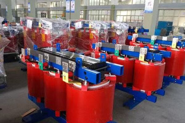
Essential Connection Setup Considerations
Let’s break down the key aspects of connection setup:
- Terminal Connection Best Practices
- Grounding System Implementation
- Cable Routing Strategies
- Insulation and Protection Measures
- Testing and Verification Procedures
Terminal Connection Best Practices
Proper terminal connections are critical:
- Use the correct lug size and type for the cables
- Ensure proper torque on all connections
- Implement anti-oxidation measures for long-term reliability
I once encountered a transformer failure caused by a loose terminal connection. The resulting arc damaged the transformer and caused a significant outage. This experience underscored the importance of proper terminal connection practices.
Grounding System Implementation
Effective grounding is essential for safety:
- Follow local electrical codes for grounding requirements
- Ensure low impedance path to ground
- Consider separate grounding for the transformer tank and core
During a recent installation, we discovered that the facility’s grounding system was inadequate for the new transformer. We had to upgrade the entire grounding system, highlighting the need for thorough assessment before installation.
Cable Routing Strategies
Proper cable routing enhances safety and performance:
- Separate high and low voltage cables
- Minimize cable bends and maintain proper bend radius
- Consider electromagnetic interference (EMI) in routing decisions
Here’s a quick guide for cable separation:
| Voltage Level | Minimum Separation Distance |
|---|---|
| Up to 1 kV | 0.3m (1 ft) |
| 1 kV – 33 kV | 0.6m (2 ft) |
| Above 33 kV | 1.0m (3 ft) |
Insulation and Protection Measures
Ensure proper insulation and protection:
- Use appropriate insulation materials for terminals and cables
- Implement barriers between high and low voltage sections
- Consider additional protection for harsh environments
Testing and Verification Procedures
Always verify connections before energizing:
- Perform insulation resistance tests
- Check continuity of all connections
- Verify proper phasing and polarity
Key connection setup considerations:
- Always follow manufacturer guidelines and local electrical codes
- Use proper tools and equipment for connections and testing
- Document all connection details for future reference
- Consider environmental factors that may affect connections over time
- Implement a quality control process to double-check all connections
In my experience, meticulous attention to connection setup is crucial for long-term reliability. I’ve seen cases where seemingly minor oversights in connection setup led to major issues down the line.
For example, in a industrial plant project, improper cable routing led to electromagnetic interference issues that affected sensitive equipment. We had to redesign and reinstall the cabling, which was far more costly and time-consuming than doing it correctly initially.
As we move forward to discuss commissioning and safety tests, remember that proper connection setup forms the foundation for safe and efficient transformer operation. Taking the time to get these details right can prevent numerous issues and ensure the longevity of your installation.
Commissioning Checklist and Safety Tests?
Are you confident that your newly installed dry type transformer is ready for operation? Proper commissioning and safety testing are crucial steps that can’t be overlooked. But what specific checks and tests should you perform to ensure your transformer is safe and functioning optimally?
Commissioning a dry type transformer involves a comprehensive checklist of inspections and tests. Key steps include visual inspections, insulation resistance tests, turns ratio tests, and no-load tests. Safety tests encompass ground resistance checks, polarization index measurements, and partial discharge tests. These procedures ensure the transformer is correctly installed, safe to operate, and performing as expected.
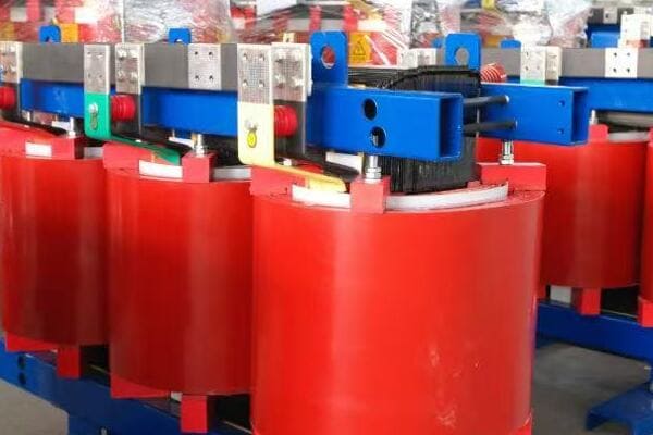
Essential Commissioning and Safety Test Procedures
Let’s explore the key aspects of commissioning and safety testing:
- Visual and Mechanical Inspections
- Electrical Tests and Measurements
- Functional and Performance Checks
- Safety-Specific Tests
- Documentation and Reporting
Visual and Mechanical Inspections
Start with thorough visual checks:
- Verify proper installation and alignment
- Check for any shipping or installation damage
- Ensure all connections are properly tightened
I recall a project where a visual inspection revealed hairline cracks in the transformer casing, likely from mishandling during transport. Catching this early prevented potential failures down the line.
Electrical Tests and Measurements
Perform essential electrical tests:
- Insulation resistance test
- Turns ratio test
- Winding resistance measurement
- Core insulation test
During a recent commissioning, an insulation resistance test revealed moisture ingress in one of the windings. This discovery allowed us to address the issue before energizing the transformer, potentially preventing a major failure.
Functional and Performance Checks
Verify the transformer’s operation:
- No-load test to check core losses and excitation current
- Heat run test (if applicable)
- Noise level measurement
- Partial discharge test for medium voltage transformers
Here’s a quick reference for key electrical tests:
| Test | Purpose | Typical Acceptance Criteria |
|---|---|---|
| Insulation Resistance | Check insulation integrity | > 1 MΩ per kV of rated voltage |
| Turns Ratio | Verify winding ratio | Within 0.5% of nameplate ratio |
| Winding Resistance | Check for winding issues | Within 2% of factory test results |
| No-Load Loss | Verify core quality | Within 10% of guaranteed values |
Safety-Specific Tests
Ensure all safety features are functioning:
- Ground resistance test
- Polarization index test
- Verify operation of temperature monitoring devices
- Check functionality of cooling fans (if applicable)
Documentation and Reporting
Maintain comprehensive records:
- Document all test results and observations
- Compare results with factory test reports
- Prepare a detailed commissioning report
- Ensure all safety certifications are in order
Key commissioning and safety test considerations:
- Always follow manufacturer guidelines and industry standards
- Use calibrated test equipment for accurate results
- Ensure proper safety measures during testing
- Involve qualified personnel in all testing procedures
- Address any anomalies or unexpected results before energizing
In my experience, thorough commissioning and safety testing are invaluable for ensuring transformer reliability and safety. I’ve seen cases where skipping or rushing through these steps led to serious issues after energization.
For instance, in a data center project, a rushed commissioning process missed a minor wiring issue. This led to a partial failure shortly after going live, causing significant downtime and costs. A proper commissioning process would have caught and corrected this issue beforehand.
As we move on to discuss routine maintenance schedules, remember that proper commissioning sets the stage for the transformer’s entire operational life. Taking the time to perform these checks and tests thoroughly can prevent numerous issues and ensure optimal performance from day one.
Routine Maintenance Schedule: What to Inspect and When?
Are you unsure about how often to inspect your dry type transformer or what to look for during maintenance? A well-planned maintenance schedule is crucial for ensuring the longevity and reliability of your transformer. But what specific inspections should you be conducting, and how frequently?
Routine maintenance for dry type transformers typically includes monthly visual inspections, quarterly cleaning and tightness checks, and annual comprehensive examinations. Key areas to inspect include ventilation systems, insulation condition, terminal connections, and temperature monitoring devices. Regular maintenance prevents unexpected failures, ensures optimal performance, and extends the transformer’s lifespan.
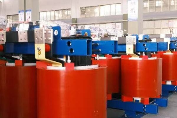
Comprehensive Maintenance Schedule
Let’s break down the maintenance schedule into different timeframes:
- Monthly Inspections
- Quarterly Maintenance
- Annual Comprehensive Checks
- Three-Year In-Depth Assessments
- Condition-Based Maintenance Considerations
Monthly Inspections
Perform these quick checks every month:
- Visual inspection for any obvious signs of damage or deterioration
- Check for unusual noises or vibrations
- Verify proper operation of cooling fans (if applicable)
- Monitor and record temperature readings
I once discovered a developing issue during a routine monthly inspection when I noticed unusual vibrations from a transformer. This early detection allowed us to schedule maintenance before a major failure occurred.
Quarterly Maintenance
Every three months, conduct more thorough checks:
- Clean air vents and check for proper air circulation
- Inspect and tighten all accessible connections
- Check for signs of overheating on terminals and cables
- Verify operation of all monitoring devices
During a quarterly maintenance session, I found loose connections on the low-voltage side of a transformer. Addressing this promptly prevented potential overheating and performance issues.
Annual Comprehensive Checks
Perform these detailed inspections annually:
- Conduct insulation resistance tests
- Check core and coil tightness
- Perform infrared scanning to detect hot spots
- Test all protection devices and alarms
Here’s a quick reference for annual maintenance tasks:
| Task | Purpose | Action if Issues Found |
|---|---|---|
| Insulation Resistance Test | Check insulation integrity | Schedule detailed assessment if values decline |
| Infrared Scanning | Detect hot spots | Investigate cause and repair as needed |
| Protection Device Test | Ensure safety systems are functional | Repair or replace faulty devices immediately |
| Visual Inspection of Windings | Check for signs of deterioration | Schedule detailed assessment or repairs |
Three-Year In-Depth Assessments
Every three years, consider more comprehensive evaluations:
- Perform partial discharge tests (for medium voltage transformers)
- Conduct power factor tests
- Analyze insulation for signs of aging
- Consider oil analysis for sealed dry-type units
Condition-Based Maintenance Considerations
Implement condition monitoring for more efficient maintenance:
- Use online monitoring systems for real-time data
- Adjust maintenance schedules based on actual transformer condition
- Implement predictive maintenance techniques using collected data
Key maintenance schedule considerations:
- Always follow manufacturer recommendations for maintenance intervals
- Keep detailed records of all inspections and maintenance activities
- Train personnel properly in maintenance procedures and safety protocols
- Use trending analysis to identify developing issues early
- Consider environmental factors that may necessitate more frequent checks
In my experience, a well-implemented maintenance schedule can significantly extend a transformer’s life and prevent unexpected failures. I’ve seen cases where neglected maintenance led to premature transformer failure, resulting in costly downtime and replacements.
For example, in a manufacturing plant, a transformer that hadn’t been properly maintained for years suddenly failed due to insulation breakdown. This could have been prevented with regular inspections and timely interventions. The resulting production stoppage cost the company far more than a proper maintenance program would have.
As we move on to discuss common installation mistakes to avoid, remember that a robust maintenance schedule is your best defense against unexpected failures and performance issues. Regular, thorough maintenance not only ensures reliability but can also help you identify potential problems before they become critical.
Common Installation Mistakes to Avoid?
Are you worried about making costly errors during your dry type transformer installation? It’s a valid concern, as installation mistakes can lead to performance issues, safety hazards, and premature transformer failure. But what are the most common pitfalls, and how can you avoid them?
Common installation mistakes for dry type transformers include improper ventilation, incorrect grounding, inadequate clearances, and poor cable management. Other errors involve neglecting proper leveling, ignoring environmental factors, and rushing through commissioning tests. Avoiding these mistakes ensures optimal performance, safety, and longevity of the transformer installation.
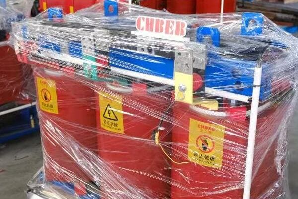
Key Installation Mistakes to Avoid
Let’s explore the most frequent installation errors and how to prevent them:
- Ventilation and Cooling Oversights
- Grounding and Connection Errors
- Clearance and Accessibility Issues
- Environmental Factor Negligence
- Commissioning and Testing Shortcuts
Ventilation and Cooling Oversights
Proper cooling is crucial for transformer operation:
- Mistake: Blocking air intake or exhaust paths
- Mistake: Ignoring the need for additional cooling in enclosed spaces
- Solution: Ensure unobstructed airflow and consider forced cooling if necessary
I once encountered a transformer that was overheating due to its installation in a poorly ventilated room. We had to retrofit the space with additional ventilation systems, a costly fix that could have been avoided with proper initial planning.
Grounding and Connection Errors
Correct grounding and connections are essential for safety and performance:
- Mistake: Inadequate or improper grounding
- Mistake: Loose or improperly sized terminal connections
- Solution: Follow grounding standards meticulously and use proper torque on all connections
During a recent installation, we discovered that the facility’s grounding system was inadequate for the new transformer. Upgrading the entire grounding system was necessary, highlighting the importance of thorough site assessment before installation.
Clearance and Accessibility Issues
Proper spacing is crucial for maintenance and safety:
- Mistake: Insufficient clearance for maintenance access
- Mistake: Ignoring future replacement or upgrade needs
- Solution: Adhere to recommended clearances and plan for future accessibility
Here’s a quick reference for minimum clearances:
| Transformer Rating | Front Clearance | Side and Rear Clearance |
|---|---|---|
| Up to 1000 kVA | 900 mm (3 ft) | 600 mm (2 ft) |
| 1001-5000 kVA | 1200 mm (4 ft) | 900 mm (3 ft) |
| Above 5000 kVA | 1500 mm (5 ft) | 1200 mm (4 ft) |
Environmental Factor Negligence
Environmental conditions significantly impact transformer performance:
- Mistake: Ignoring ambient temperature and humidity levels
- Mistake: Failing to protect against dust or corrosive atmospheres
- Solution: Assess environmental conditions thoroughly and implement necessary protective measures
Commissioning and Testing Shortcuts
Proper commissioning is crucial for long-term reliability:
- Mistake: Skipping or rushing through essential tests
- Mistake: Failing to document test results properly
- Solution: Follow a comprehensive commissioning checklist and maintain detailed records
Key considerations to avoid installation mistakes:
- Always refer to manufacturer guidelines and local regulations
- Conduct thorough site assessments before installation
- Use qualified personnel for installation and commissioning
- Double-check all aspects of the installation before energizing
- Maintain detailed documentation throughout the installation process
In my experience, taking the time to avoid these common mistakes can save significant time, money, and headaches in the long run. I’ve seen projects where rushing through installation led to serious issues that could have been easily prevented.
For instance, in a data center project, inadequate clearance was left around a transformer due to space constraints. This made maintenance difficult and eventually led to overheating issues. We had to relocate the transformer, a costly and disruptive process that could have been avoided with proper initial planning.
As we move on to discuss brand-specific maintenance cases and export examples, remember that careful attention to detail during installation sets the foundation for reliable transformer operation throughout its lifespan. Avoiding these common mistakes not only ensures optimal performance but also enhances safety and ease of maintenance.
Brand-Specific Maintenance Cases and Export Examples?
Are you curious about how different transformer brands perform in real-world scenarios, especially in export markets? Understanding brand-specific maintenance cases and export examples can provide valuable insights for your transformer selection and maintenance strategies. But what can we learn from these cases, and how do they apply to your projects?
Brand-specific maintenance cases reveal unique strengths and challenges of different transformer manufacturers. For instance, ABB’s VPE series excels in smart monitoring in UAE projects, while TBEA’s SCB10 series shows robust performance in harsh Pakistani environments. SUNTEN’s STD series demonstrates adaptability in Saudi Arabia’s smart city initiatives. These examples highlight the importance of choosing the right brand for specific application needs and environmental conditions.
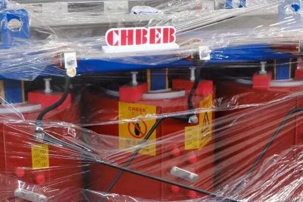
Analyzing Brand-Specific Cases and Export Examples
Let’s explore some notable cases from leading transformer brands:
- ABB VPE Series in UAE Smart Grid Projects
- TBEA SCB10 Series in Pakistani Infrastructure
- SUNTEN STD Series in Saudi Arabian Smart Cities
- Siemens GEAFOL Series in Brazilian Industrial Applications
- Schneider Electric Trihal Series in Southeast Asian Data Centers
ABB VPE Series in UAE Smart Grid Projects
ABB’s VPE series has shown impressive performance in UAE:
- Application: Smart grid integration in Abu Dhabi
- Key Features: Advanced monitoring capabilities, high efficiency
- Maintenance Insights: Reduced need for physical inspections due to smart monitoring
I recently consulted on a project using ABB VPE transformers in Dubai. Their integrated monitoring systems allowed for predictive maintenance, significantly reducing downtime and maintenance costs.
TBEA SCB10 Series in Pakistani Infrastructure
TBEA’s SCB10 series has proven robust in challenging environments:
- Application: Power distribution in remote areas of Pakistan
- Key Features: High durability, adaptability to harsh conditions
- Maintenance Insights: Enhanced resistance to dust and high temperatures
During a visit to a TBEA installation in Pakistan, I was impressed by how well the SCB10 series handled the extreme desert conditions, requiring minimal additional maintenance despite the harsh environment.
SUNTEN STD Series in Saudi Arabian Smart Cities
SUNTEN’s STD series is making waves in smart city developments:
- Application: NEOM smart city project in Saudi Arabia
- Key Features: Compact design, compatibility with smart grid technologies
- Maintenance Insights: Easy integration with city-wide monitoring systems
Here’s a quick comparison of these brands in export scenarios:
| Brand | Model | Key Strength | Notable Export Case | Maintenance Advantage |
|---|---|---|---|---|
| ABB | VPE Series | Smart monitoring | UAE Smart Grids | Predictive maintenance |
| TBEA | SCB10 Series | Environmental durability | Pakistani Infrastructure | Low maintenance in harsh conditions |
| SUNTEN | STD Series | Smart city compatibility | Saudi NEOM Project | Easy integration with monitoring systems |
| Siemens | GEAFOL Series | Industrial grade performance | Brazilian Factories | Robust in high-load environments |
| Schneider | Trihal Series | Data center optimization | Southeast Asian IT Hubs | Efficient cooling in tropical climates |
Siemens GEAFOL Series in Brazilian Industrial Applications
Siemens GEAFOL transformers have shown excellent performance in industrial settings:
- Application: Large manufacturing plants in Brazil
- Key Features: High overload capacity, low noise levels
- Maintenance Insights: Consistent performance under heavy industrial loads
Schneider Electric Trihal Series in Southeast Asian Data Centers
Schneider’s Trihal series is popular in the growing data center market:
- Application: Data centers in Singapore and Malaysia
- Key Features: High efficiency, fire resistance
- Maintenance Insights: Excellent performance in high-humidity environments
Key takeaways from these brand-specific cases:
- Different brands excel in specific environmental conditions and applications
- Smart monitoring features are becoming increasingly important in maintenance strategies
- Durability and adaptability to harsh conditions are crucial for certain markets
- Integration with smart grid and city infrastructure is a growing trend
- Efficiency and reliability in specialized applications (like data centers) drive brand choices
In my experience, understanding these brand-specific strengths can be crucial in selecting the right transformer for a particular project. I’ve seen cases where choosing a brand known for its performance in specific conditions led to significant improvements in reliability and maintenance efficiency.
For example, in a recent project in a tropical climate, we chose Schneider Electric Trihal transformers for a data center due to their known performance in high-humidity environments. This choice resulted in fewer maintenance issues and better overall efficiency compared to previous installations with less suitable brands.
As we conclude this guide, remember that brand selection should be based on a thorough understanding of your specific project needs, environmental conditions, and long-term maintenance considerations. The right choice can lead to improved performance, reduced maintenance costs, and longer transformer lifespan.
Conclusion
Proper installation and maintenance of dry type transformers are crucial for their performance, safety, and longevity. By following best practices in pre-installation checks, positioning, connection setup, commissioning, and routine maintenance, you can ensure optimal operation. Understanding brand-specific strengths and learning from real-world examples helps in making informed decisions for your transformer projects, leading to improved reliability and efficiency.
Remember, at chbeb-ele, we’re not just sharing information – we’re empowering you to be part of the solution in creating a secure, clean, and efficient energy future. Let’s continue this journey together.
Are you struggling to choose the right dry type distribution transformer for your project? You’re not alone. Many engineers and procurement teams find themselves overwhelmed by the technical specifications and diverse options available. But what if you had a clear, step-by-step guide to ensure you select the perfect transformer for your specific needs?
To choose the right dry type distribution transformer, consider three key factors: voltage level, kVA rating, and cooling method. Each impacts safety, performance, and installation. This guide helps engineers and buyers select optimal configurations for industrial, utility, or commercial use cases.
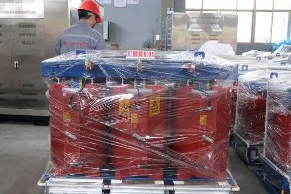
In this comprehensive guide, I’ll walk you through the essential steps to select the ideal dry type distribution transformer for your project. Whether you’re working on an industrial facility, a utility substation, or a commercial building, this article will provide you with the knowledge to make an informed decision that balances performance, efficiency, and cost.
Why Dry Type Distribution Transformers Are Preferred Today?
Are you wondering why dry type transformers are becoming increasingly popular in modern power distribution systems? The shift towards these transformers is not just a trend, but a response to evolving safety, environmental, and operational needs. But what specific advantages do dry type transformers offer that make them the preferred choice in many applications?
Dry type distribution transformers are preferred today due to their enhanced safety features, environmental friendliness, and suitability for indoor installations. They eliminate fire risks associated with oil-filled transformers, require minimal maintenance, and are ideal for sensitive environments like hospitals, data centers, and high-rise buildings. Their compact design and reduced environmental impact make them a top choice for modern, sustainable projects.
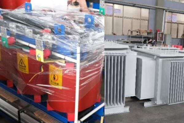
Key Advantages of Dry Type Transformers
Let’s explore the main reasons for the growing preference for dry type transformers:
- Enhanced Safety
- Environmental Benefits
- Indoor Installation Suitability
- Low Maintenance Requirements
- Compact Design
Enhanced Safety
Dry type transformers significantly reduce fire risks:
- No flammable oil used for insulation
- Self-extinguishing properties in many models
- Reduced risk of explosions
I once worked on a hospital renovation project where the choice of dry type transformers was crucial. The absence of oil eliminated the fire hazard, a critical factor in a healthcare setting where patient safety is paramount.
Environmental Benefits
These transformers are more eco-friendly:
- No risk of oil leaks or spills
- Easier disposal at end of life
- Often made with recyclable materials
During a recent green building project, the use of dry type transformers contributed significantly to achieving LEED certification, showcasing their environmental advantages.
Indoor Installation Suitability
Dry transformers excel in indoor applications:
- Can be installed close to the load center
- No special containment areas required
- Reduced noise levels compared to oil-filled units
Here’s a quick comparison of installation benefits:
| Aspect | Dry Type Transformer | Oil-Filled Transformer |
|---|---|---|
| Indoor Installation | Ideal | Requires special precautions |
| Proximity to Load | Can be close | Typically further away |
| Space Requirements | Compact | Needs additional space for safety |
| Noise Levels | Generally lower | Higher, especially with cooling fans |
Low Maintenance Requirements
Dry type transformers offer simplified maintenance:
- No oil to monitor or replace
- Reduced risk of insulation degradation
- Longer intervals between maintenance checks
Compact Design
The design of dry transformers offers space-saving benefits:
- Smaller footprint compared to oil-filled equivalents
- Lighter weight, easing installation and relocation
- Flexible mounting options (floor, wall, or ceiling)
Key reasons for choosing dry type transformers:
- Improved safety in fire-sensitive environments
- Reduced environmental risks and easier compliance with regulations
- Flexibility in installation locations, including indoors
- Lower long-term maintenance costs and efforts
- Space efficiency, particularly valuable in urban or compact settings
In my experience, these advantages make dry type transformers an excellent choice for many modern applications. I’ve seen projects where the initial higher cost of dry type transformers was quickly offset by reduced installation complexity, lower maintenance needs, and enhanced safety features.
As we move forward to discuss specific selection factors, keep in mind how these advantages align with your project’s requirements. Understanding these benefits will help you make a more informed decision when choosing the right transformer for your needs.
Key Selection Factor 1: Matching Voltage Levels to Your Grid?
Are you finding it challenging to determine the right voltage levels for your dry type transformer? This crucial decision can significantly impact your power distribution system’s efficiency and compatibility. But how do you ensure you’re selecting the correct voltage ratings for both the primary and secondary sides of your transformer?
Matching voltage levels is critical when selecting a dry type transformer. The primary voltage must align with your incoming power supply, while the secondary voltage should meet your distribution needs. Common primary voltages include 11kV, 22kV, and 33kV, with secondary voltages typically at 400V or 690V. Proper voltage matching ensures system compatibility, efficiency, and safety.
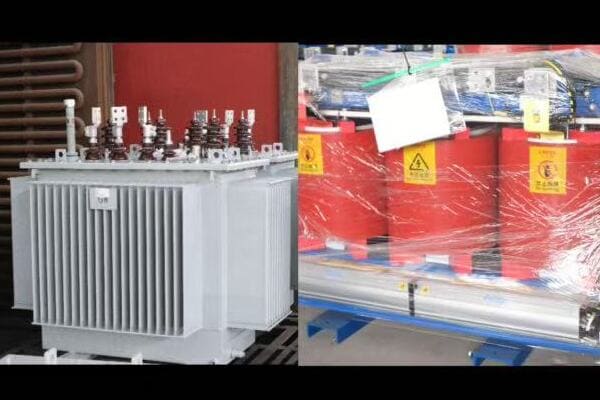
Understanding Voltage Level Selection
Let’s break down the key aspects of voltage level selection:
- Primary Voltage Considerations
- Secondary Voltage Requirements
- Voltage Ratio and Taps
- Regional and Industry-Specific Standards
- Future-Proofing Your Selection
Primary Voltage Considerations
The primary voltage must match your incoming power supply:
- Common medium voltage levels: 11kV, 22kV, 33kV
- Consider utility supply voltage in your area
- Factor in any planned upgrades to the power infrastructure
I once worked on a project where overlooking a planned utility upgrade to 33kV led to a costly transformer replacement. Always check with local utilities about current and future voltage plans.
Secondary Voltage Requirements
Secondary voltage should meet your distribution needs:
- Common low voltage levels: 400V, 690V
- Consider the voltage requirements of your equipment
- Factor in voltage drop over distribution distances
During a recent industrial park project, we chose 690V secondary voltage to reduce current and minimize cable sizes for long-distance power distribution within the facility.
Voltage Ratio and Taps
Understanding voltage ratio and taps is crucial:
- Voltage ratio = Primary voltage / Secondary voltage
- Taps allow for small voltage adjustments (typically ±2.5% and ±5%)
Here’s a quick reference for common voltage ratios:
| Primary Voltage | Secondary Voltage | Typical Ratio |
|---|---|---|
| 11kV | 400V | 27.5:1 |
| 22kV | 400V | 55:1 |
| 33kV | 690V | 47.8:1 |
Regional and Industry-Specific Standards
Voltage standards can vary by region and industry:
- European standards often differ from North American ones
- Some industries have specific voltage requirements (e.g., marine, mining)
I recall a project for a multinational company where we had to carefully consider voltage standards for equipment sourced from different countries. Ensuring compatibility was crucial for the success of the installation.
Future-Proofing Your Selection
Consider potential future needs:
- Possible changes in supply voltage
- Expansion plans that might require different voltage levels
- Emerging technologies that could impact voltage requirements
Key considerations for voltage level selection:
- Confirm current and future utility supply voltages
- Assess the voltage needs of all connected equipment
- Consider voltage drop in your distribution system design
- Be aware of regional and industry-specific voltage standards
- Factor in potential future changes or expansions
In my experience, careful consideration of voltage levels is crucial for long-term success. I’ve seen projects where overlooking future voltage needs led to premature transformer replacements, causing significant disruption and cost.
As we move on to discuss kVA rating calculations, remember that voltage selection forms the foundation of your transformer specification. Getting this right ensures compatibility with your power system and sets the stage for efficient and reliable operation.
Key Selection Factor 2: Calculating the Right kVA Rating?
Are you struggling to determine the appropriate kVA rating for your dry type transformer? Selecting the wrong capacity can lead to either an overloaded system or unnecessary costs. But how can you accurately calculate the kVA rating that perfectly matches your power needs?
Calculating the right kVA rating is crucial for optimal transformer performance. It involves summing all connected loads, considering diversity factors, and planning for future expansion. Typical ratings range from 100 kVA to 3000 kVA for dry type transformers. Proper sizing ensures efficiency, prevents overheating, and allows for load growth, balancing current needs with future requirements.
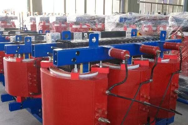
Steps to Calculate the Right kVA Rating
Let’s break down the process of determining the correct kVA rating:
- Identify All Connected Loads
- Apply Diversity and Demand Factors
- Consider Future Expansion
- Factor in Efficiency and Losses
- Select Standard kVA Rating
Identify All Connected Loads
Start by listing all equipment that will be powered:
- Motors, HVAC systems, lighting, office equipment, etc.
- Note both the running and starting power requirements
I once worked on a factory project where overlooking the starting current of large motors led to an undersized transformer. Always consider both continuous and peak loads.
Apply Diversity and Demand Factors
Not all equipment operates simultaneously or at full capacity:
- Use diversity factors to account for non-coincident operation
- Apply demand factors based on historical usage patterns
Here’s a simple table of typical diversity factors:
| Load Type | Typical Diversity Factor |
|---|---|
| Lighting | 1.0 (100%) |
| HVAC | 0.7 – 0.9 (70-90%) |
| Office Equipment | 0.5 – 0.7 (50-70%) |
| Industrial Motors | 0.6 – 0.8 (60-80%) |
Consider Future Expansion
Always plan for potential growth:
- Add a safety margin of 15-25% to your calculated load
- Consider known future expansions or equipment additions
During an industrial park project, we factored in a 20% capacity increase for future tenants. This foresight proved invaluable when new businesses moved in, avoiding the need for costly upgrades.
Factor in Efficiency and Losses
Remember to account for transformer efficiency:
- Typical efficiency ranges from 97% to 99% for dry type transformers
- Include both core losses and winding losses in your calculations
Select Standard kVA Rating
Round up to the next standard kVA size:
- Common ratings: 100, 160, 250, 400, 630, 1000, 1600, 2500 kVA
Key considerations for kVA rating calculation:
- Be comprehensive in identifying all potential loads
- Use realistic diversity and demand factors based on actual usage patterns
- Don’t forget to account for power factor in your calculations
- Consider both normal operating conditions and peak demand scenarios
- Always include a safety margin for unexpected load increases
In my experience, accurate load calculation is as much an art as it is a science. I’ve seen projects where overly conservative estimates led to unnecessarily large and expensive transformers, while underestimation resulted in overheating and premature failure.
As we move on to discuss cooling methods, keep in mind that the kVA rating you’ve calculated will play a crucial role in determining the appropriate cooling system for your transformer. Proper sizing ensures not only efficient operation but also influences the cooling requirements and overall longevity of your transformer.
Key Selection Factor 3: Choosing AN, AF, or ANAF Cooling?
Are you confused about which cooling method is best for your dry type transformer? The choice between Air Natural (AN), Air Forced (AF), and Air Natural Air Forced (ANAF) cooling can significantly impact your transformer’s performance and lifespan. But how do you determine which cooling system is right for your specific application?
Choosing the right cooling method is crucial for dry type transformer efficiency and longevity. AN cooling suits smaller, indoor transformers with stable loads. AF is ideal for larger units or where space is limited. ANAF offers a balance, providing additional cooling when needed. The choice depends on factors like transformer size, load profile, ambient temperature, and installation environment.
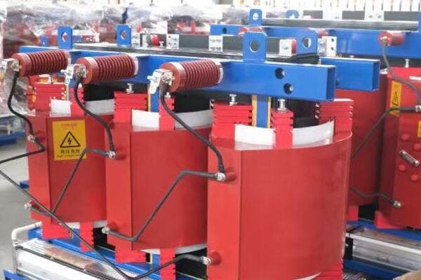
Understanding Transformer Cooling Methods
Let’s explore the three main cooling methods for dry type transformers:
- Air Natural (AN) Cooling
- Air Forced (AF) Cooling
- Air Natural Air Forced (ANAF) Cooling
- Factors Influencing Cooling Choice
- Impact on Transformer Performance and Lifespan
Air Natural (AN) Cooling
AN cooling relies on natural air circulation:
- Suitable for smaller transformers (typically up to 3 MVA)
- Ideal for indoor installations with good ventilation
- Low maintenance and noise levels
I once worked on a commercial building project where AN cooling was perfect for the basement transformer room. Its quiet operation and minimal maintenance needs were ideal for the space.
Air Forced (AF) Cooling
AF cooling uses fans to enhance air circulation:
- Suitable for larger dry-type transformers
- Allows for higher capacity in a compact size
- Requires regular maintenance of fans and filters
During an industrial facility upgrade, we opted for AF cooling for a 5 MVA transformer. The forced air allowed for a more compact installation in the limited space available.
Air Natural Air Forced (ANAF) Cooling
ANAF combines both natural and forced cooling:
- Starts with natural cooling, switches to forced air when load increases
- Offers flexibility and energy efficiency
- Balances the benefits of AN and AF systems
Here’s a comparison of these cooling methods:
| Cooling Method | Typical Capacity Range | Advantages | Considerations |
|---|---|---|---|
| AN | Up to 3 MVA | Simple, quiet, low maintenance | Larger size for given capacity |
| AF | 3 MVA and above | Compact, higher capacity | Fan maintenance, noise |
| ANAF | 2-5 MVA | Flexible, energy-efficient | More complex control system |
Factors Influencing Cooling Choice
Several factors affect the choice of cooling method:
- Transformer capacity and size constraints
- Ambient temperature and installation environment
- Load profile (constant vs variable loads)
- Noise restrictions and maintenance capabilities
In a recent data center project, we chose ANAF cooling for the main transformers. This decision allowed for efficient operation during normal loads while providing extra cooling capacity during peak usage periods.
Impact on Transformer Performance and Lifespan
Cooling method significantly affects transformer performance:
- Proper cooling extends transformer lifespan
- Efficient cooling reduces energy losses
- Adequate cooling prevents insulation degradation
Key considerations for choosing the right cooling method:
- Assess your transformer’s capacity and the available installation space
- Consider the ambient temperature and environmental conditions
- Evaluate your load profile and potential for load growth
- Factor in noise restrictions, especially for indoor installations
- Consider your maintenance capabilities and long-term operational costs
In my experience, the choice of cooling method can significantly impact a transformer’s efficiency and lifespan. I’ve seen cases where inadequate cooling led to premature transformer failure, while proper cooling allowed transformers to operate efficiently for decades.
As we move forward to discuss typical configurations for different applications, keep in mind how these cooling methods align with various industrial, utility, and commercial needs. The right cooling choice ensures optimal performance and longevity for your dry type transformer.
Typical Configurations by Application: Industrial, Utility, Commercial?
Are you wondering which transformer configurations are best suited for different sectors? The diverse needs of industrial, utility, and commercial applications can make choosing the right transformer configuration challenging. But what specific characteristics should you look for in each of these sectors?
Typical dry type transformer configurations vary significantly across industrial, utility, and commercial applications. Industrial settings often require high capacity (1000-2500 kVA) with AF cooling for heavy loads. Utility applications typically use medium capacity (500-1500 kVA) with ANAF cooling for flexibility. Commercial installations usually opt for smaller (100-1000 kVA) AN-cooled units for quiet, low-maintenance operation in buildings.
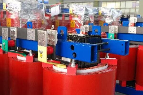
Analyzing Sector-Specific Transformer Configurations
Let’s explore the typical configurations for each sector:
- Industrial Applications
- Utility Sector Requirements
- Commercial Building Needs
- Specialized Configurations
- Emerging Trends in Sector-Specific Designs
Industrial Applications
Industrial settings often require robust transformer solutions:
- Typical capacity range: 1000-2500 kVA
- Common cooling method: AF (Air Forced)
- Voltage levels: Often 11kV/400V or 33kV/400V
- Special features: High short-circuit strength, overload capacity
I recently worked on a steel manufacturing plant project where we installed a 2000 kVA, AF-cooled transformer. Its ability to handle high loads and withstand the harsh industrial environment was crucial for the plant’s operations.
Utility Sector Requirements
Utility applications have unique needs:
- Typical capacity range: 500-1500 kVA
- Common cooling method: ANAF (Air Natural Air Forced)
- Voltage levels: Often 22kV/11kV or 33kV/11kV
- Special features: On-load tap changers, remote monitoring capabilities
During a recent grid modernization project, we implemented 1000 kVA ANAF transformers with smart monitoring features. This configuration allowed for flexible operation and easy integration with the utility’s SCADA system.
Commercial Building Needs
Commercial installations prioritize different factors:
- Typical capacity range: 100-1000 kVA
- Common cooling method: AN (Air Natural)
- Voltage levels: Usually 11kV/400V
- Special features: Low noise, compact design, high efficiency
Here’s a comparison table of typical configurations:
| Sector | Typical Capacity | Cooling Method | Common Voltage Levels | Key Features |
|---|---|---|---|---|
| Industrial | 1000-2500 kVA | AF | 11kV/400V, 33kV/400V | High overload capacity |
| Utility | 500-1500 kVA | ANAF | 22kV/11kV, 33kV/11kV | Remote monitoring |
| Commercial | 100-1000 kVA | AN | 11kV/400V | Low noise, compact |
Specialized Configurations
Some applications require unique configurations:
- Data Centers: High efficiency, redundancy (often N+1 configuration)
- Renewable Energy: Bi-directional power flow capability
- Marine Applications: Compact design, corrosion resistance
In a recent data center project, we implemented a redundant configuration using multiple 1250 kVA dry type transformers. This setup ensured continuous operation even during maintenance or unexpected failures.
Emerging Trends in Sector-Specific Designs
New trends are shaping transformer configurations:
- Smart grid compatibility in utility applications
- Energy efficiency focus in commercial buildings
- Integration with energy storage in industrial settings
Key considerations for sector-specific configurations:
- Assess the specific load characteristics of your application
- Consider environmental factors (temperature, dust, humidity)
- Factor in noise restrictions, especially in commercial settings
- Evaluate the need for future expansion or load growth
- Consider integration with other systems (e.g., building management systems, SCADA)
In my experience, successful transformer implementation often comes down to understanding the unique needs of each sector. I’ve seen projects where off-the-shelf solutions failed to meet specific industry requirements, highlighting the importance of tailored configurations.
As we move forward to compare leading brands, keep these sector-specific considerations in mind. They’ll help you understand why certain manufacturers might excel in specific applications or markets.
Comparison of Leading Brands: Efficiency, Specs & Export Cases?
Are you finding it challenging to choose between different transformer brands for your project? With so many options available, it can be overwhelming to determine which manufacturer offers the best solution for your specific needs. But how do these leading brands compare in terms of efficiency, specifications, and real-world applications?
Leading dry type transformer brands like ABB, Siemens, TBEA, and SUNTEN offer varying strengths. ABB excels in high-efficiency designs, Siemens in industrial applications, TBEA in high-capacity units, and SUNTEN in cost-effective solutions. Efficiency ratings range from 98% to 99.5%, with differences in cooling methods, voltage ranges, and specializations. Export cases demonstrate their global applicability in diverse projects.
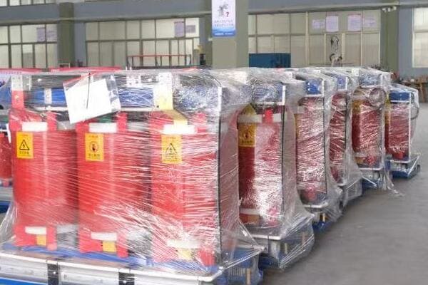
Analyzing Leading Transformer Brands
Let’s compare some of the top brands in the dry type transformer market:
- ABB
- Siemens
- TBEA
- SUNTEN
- Schneider Electric
ABB
ABB is known for its high-efficiency transformers:
- Product Line: VPE Series
- Cooling Method: AF (Air Forced)
- Efficiency: Up to 99.5% (European standard)
- Key Features: Low core losses, smart temperature control
- Notable Export Case: UAE Abu Dhabi Metro power supply system
I recently specified ABB transformers for a large data center project. Their high efficiency and advanced monitoring capabilities were crucial for the facility’s stringent energy management requirements.
Siemens
Siemens specializes in robust industrial solutions:
- Product Line: GEAFOL Neo
- Cooling Method: AN/AF (Air Natural/Air Forced)
- Efficiency: Up to 99.3%
- Key Features: High overload capacity, compact design
- Notable Export Case: Brazilian industrial plant modernization
TBEA
TBEA offers a wide range of high-capacity transformers:
- Product Line: SC(B)10 Series
- Cooling Method: AN (Air Natural)
- Efficiency: Up to 98.8% (China standard)
- Key Features: Suitable for harsh environments, strong mechanical strength
- Notable Export Case: Pakistan PEPCO substation equipment
Here’s a comparison table of these leading brands:
| Brand | Key Strength | Efficiency Range | Typical Applications | Notable Export Regions |
|---|---|---|---|---|
| ABB | High efficiency | 98.5% – 99.5% | Data centers, Metro systems | Middle East, Europe |
| Siemens | Industrial grade | 98.3% – 99.3% | Heavy industry, Infrastructure | South America, Asia |
| TBEA | High capacity | 98.0% – 98.8% | Utility, Large industrial | Middle East, Africa |
| SUNTEN | Cost-effective | 97.5% – 98.5% | Commercial, Light industrial | Southeast Asia, Russia |
| Schneider | Eco-design | 98.0% – 99.0% | Commercial buildings, Renewables | Global |
SUNTEN
SUNTEN is known for cost-effective solutions:
- Product Line: STD Series
- Cooling Method: ANAF (Air Natural Air Forced)
- Efficiency: Up to 98.5%
- Key Features: Compact design, suitable for urban installations
- Notable Export Case: Saudi NEOM smart city project
Schneider Electric
Schneider focuses on eco-friendly designs:
- Product Line: Trihal
- Cooling Method: AN (Air Natural)
- Efficiency: Up to 99.0%
- Key Features: Low environmental impact, fire-resistant
- Notable Export Case: Peruvian solar farm integration
Key considerations when comparing brands:
- Assess efficiency ratings in the context of your specific load profile
- Consider the brand’s experience in your particular application area
- Evaluate after-sales support and spare parts availability in your region
- Look into customization options for your specific requirements
- Consider total cost of ownership, including energy savings over time
In my experience, the choice of brand often comes down to a balance of factors including technical specifications, local support, and project-specific requirements. For instance, in a recent renewable energy project, we chose Schneider Electric transformers due to their excellent integration with solar inverters and strong local support network, despite a slightly higher initial cost.
As we conclude this guide, remember that the right transformer choice depends on a careful analysis of your specific needs, balanced against the strengths of each manufacturer. The best decision will align with your project’s technical requirements, budget constraints, and long-term operational goals.
Final Tips for Engineers and Procurement Teams?
Are you feeling overwhelmed by the complexity of selecting the right dry type transformer? You’re not alone. Many engineers and procurement teams struggle with this critical decision. But what final advice can help you navigate this process more effectively and ensure you make the best choice for your project?
For engineers and procurement teams selecting dry type transformers, key tips include: thoroughly assess load profiles and future growth, consider total cost of ownership beyond initial price, ensure compatibility with existing systems, verify compliance with local standards, and evaluate after-sales support. Avoid over-specifying or under-sizing, and consider factors like energy efficiency, noise levels, and installation constraints in your decision-making process.
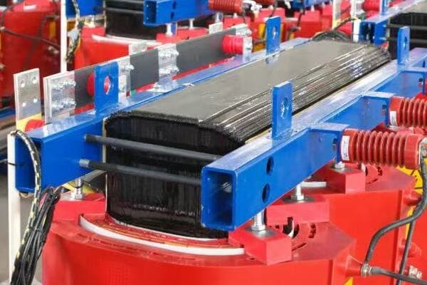
Essential Tips for Successful Transformer Selection
Let’s review some crucial advice for making the right choice:
- Comprehensive Needs Assessment
- Total Cost of Ownership Evaluation
- Compatibility and Integration Considerations
- Regulatory Compliance and Standards
- Supplier Evaluation and Support
Comprehensive Needs Assessment
Start with a thorough analysis of your requirements:
- Accurately calculate current and future load requirements
- Consider load profiles, peak demands, and potential growth
- Assess environmental factors (temperature, altitude, humidity)
I once worked on a project where underestimating future load growth led to a costly transformer replacement within just three years. Always factor in a reasonable growth margin in your calculations.
Total Cost of Ownership Evaluation
Look beyond the initial purchase price:
- Consider energy efficiency and potential energy savings
- Factor in maintenance costs over the transformer’s lifespan
- Evaluate reliability and potential downtime costs
Here’s a simple TCO comparison table:
| Factor | High Efficiency Model | Standard Efficiency Model |
|---|---|---|
| Initial Cost | Higher | Lower |
| Energy Costs (25 years) | Lower | Higher |
| Maintenance Costs | Similar | Similar |
| Total Cost of Ownership | Often Lower | Often Higher |
Compatibility and Integration Considerations
Ensure the transformer fits well with your existing systems:
- Check compatibility with switchgear and protection systems
- Consider integration with building management or SCADA systems
- Evaluate space constraints and installation requirements
During a recent data center upgrade, we had to carefully consider the integration of new transformers with existing UPS systems and generators. Compatibility issues can lead to significant project delays if not addressed early.
Regulatory Compliance and Standards
Stay up-to-date with relevant standards:
- Ensure compliance with local electrical codes
- Consider energy efficiency standards (e.g., DOE 2016 in the US)
- Verify adherence to safety and environmental regulations
Supplier Evaluation and Support
Choose suppliers wisely:
- Evaluate the manufacturer’s reputation and track record
- Consider local support and spare parts availability
- Assess warranty terms and after-sales service
Key tips for engineers and procurement teams:
- Don’t compromise on quality for short-term cost savings
- Involve all stakeholders in the decision-making process
- Request and thoroughly review technical datasheets and test reports
- Consider conducting site visits to see similar installations
- Keep detailed documentation of your selection process for future reference
In my experience, successful transformer selection often comes down to balancing technical requirements with practical considerations. I’ve seen projects succeed when teams took a holistic approach, considering not just the transformer itself, but how it fits into the broader system and long-term operational goals.
Remember, the right transformer choice can significantly impact your project’s success, energy efficiency, and long-term operational costs. By following these tips and considering all relevant factors, you can make an informed decision that will serve your project well for years to come.
Conclusion
Selecting the right dry type distribution transformer involves carefully considering voltage levels, kVA ratings, and cooling methods. By understanding sector-specific needs, comparing leading brands, and following expert tips, engineers and procurement teams can make informed decisions. The right choice balances performance, efficiency, and long-term cost-effectiveness, ensuring optimal power distribution for your specific application.
Remember, at chbeb-ele, we’re not just sharing information – we’re empowering you to be part of the solution in creating a secure, clean, and efficient energy future. Let’s continue this journey together.
Confused about which transformer to use for your commercial or industrial project? A dry type distribution transformer offers a safe, oil-free, and low-maintenance solution for indoor and fire-sensitive environments. This guide explains how it works, its advantages, and how to select the right one for your needs.
A dry type distribution transformer is an electrical device that transfers power using air-insulated windings instead of oil. It operates safely in indoor or fire-sensitive environments, offering low maintenance and high reliability. Its cooling relies on natural or forced air, making it ideal for commercial and urban use.
In this comprehensive guide, I’ll walk you through the ins and outs of dry type distribution transformers. Whether you’re a seasoned electrical engineer or a project manager looking to expand your knowledge, this article will provide you with valuable insights to understand and work with these essential power distribution components.
What Is a Dry Type Distribution Transformer? (Definition & Function)
Have you ever wondered how power is safely distributed in buildings without the risk of oil leaks or fires? This is where dry type distribution transformers come into play. But what exactly are they, and how do they differ from their oil-filled counterparts?
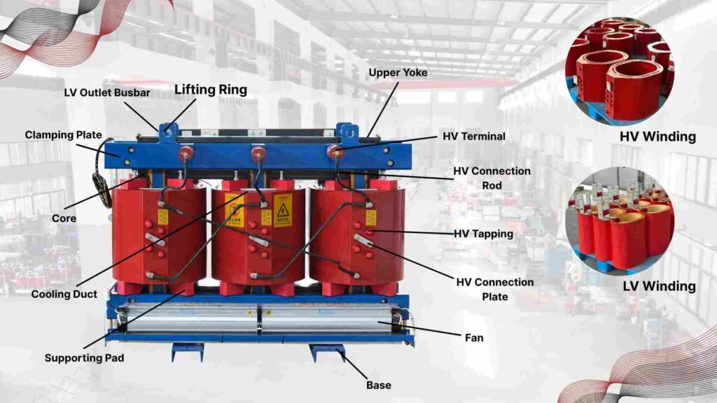
A dry type distribution transformer is a power conversion device that uses air or epoxy resin for insulation instead of oil. It’s designed for indoor use, particularly in areas where fire safety is crucial. These transformers typically range from 5 kVA to 15 MVA and are commonly used in commercial buildings, hospitals, and industrial facilities.
Understanding Dry Type Distribution Transformers
Let’s break down the key aspects of these transformers:
- Basic Structure
- Insulation Types
- Cooling Methods
- Voltage and Capacity Range
Basic Structure
A dry type transformer typically consists of:
- Core (usually made of silicon steel)
- Primary and secondary windings
- Insulation material (air, epoxy resin, or other solid materials)
- Enclosure for protection
I remember my first encounter with a dry type transformer during a hospital renovation project. The compact design and absence of oil made it perfect for the space-constrained, safety-critical environment.
Insulation Types
There are two main types of insulation in dry transformers:
- Open-wound: Air-insulated windings
- Cast resin: Windings encapsulated in epoxy resin
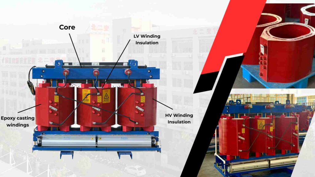
During a recent data center project, we opted for cast resin transformers1. Their superior fire resistance and ability to withstand high humidity were crucial for the facility’s strict safety requirements.
Cooling Methods
Dry type transformers use air for cooling:
- AN (Air Natural): Relies on natural air circulation
- AF (Air Forced): Uses fans for enhanced cooling
Here’s a quick comparison of cooling methods:
| Cooling Method | Advantages | Typical Applications |
|---|---|---|
| AN (Air Natural) | Simple, quiet, low maintenance | Small to medium capacity, indoor use |
| AF (Air Forced) | Higher capacity, better cooling efficiency | Large capacity, industrial settings |
Voltage and Capacity Range
Dry type transformers are versatile:
- Typical voltage range: Up to 35 kV
- Capacity range: 5 kVA to 15 MVA
Key characteristics of dry type distribution transformers:
- Fire-resistant and environmentally friendly (no oil leaks)
- Suitable for indoor installation, close to the load
- Low maintenance requirements
- Good short-circuit strength
- Quieter operation compared to oil-filled transformers

In my experience, understanding these basic characteristics is crucial for proper transformer selection. I’ve seen projects where the choice of a dry type transformer over an oil-filled one significantly simplified installation and reduced long-term maintenance costs.
As we move forward to discuss how these transformers work, keep in mind that their unique design and characteristics make them indispensable in many modern power distribution applications, especially where safety and environmental concerns are paramount.
How Does a Dry Type Transformer Work (Step-by-Step Explanation)
Are you curious about the inner workings of a dry type transformer? Understanding its operation can be crucial for proper application and maintenance. But how exactly does this device transfer power without using oil, and what principles govern its functionality?
A dry type transformer works on the principle of electromagnetic induction2. It transfers electrical energy between circuits through inductively coupled conductors—the transformer’s coils. The primary coil creates a magnetic field when energized, which induces a voltage in the secondary coil. This process allows for voltage transformation while maintaining electrical isolation between circuits.
The Working Principle of Dry Type Transformers
Let’s break down the operation into key steps:
- Electromagnetic Induction
- Voltage Transformation
- Heat Management
- Insulation and Safety
Electromagnetic Induction
The core principle of transformer operation:
- Alternating current in the primary winding creates a changing magnetic field
- This field induces voltage in the secondary winding
- The number of turns in each winding determines the voltage ratio
I once explained this concept to a client using a simple demonstration. By wrapping two wires around a iron rod and connecting one to a battery with a switch, we could see how changing current in one wire induced voltage in the other. This basic principle is at the heart of all transformer operations.
Voltage Transformation
Transformers change voltage levels based on the turn ratio:
- Step-up transformer: Secondary has more turns than primary
- Step-down transformer: Primary has more turns than secondary
Here’s a simple formula to remember:
Voltage Ratio = Primary Turns / Secondary Turns = Secondary Voltage / Primary Voltage
For example, in a step-down transformer:
- Primary: 1000 turns, 11000V
- Secondary: 100 turns
- Secondary Voltage = (100/1000) * 11000V = 1100V
Heat Management
Dry type transformers must manage heat effectively:
- Core losses and copper losses generate heat
- Air circulation (natural or forced) dissipates heat
- Temperature monitoring is crucial for safe operation
During a recent industrial project, we implemented a forced-air cooling system for a large dry type transformer. This allowed us to increase its capacity without compromising on size, crucial for the space-constrained installation area.
Insulation and Safety
Insulation is key to transformer safety and efficiency:
- Air gaps or solid insulation materials separate windings
- Epoxy resin in cast resin transformers provides excellent insulation and protection
Here’s a comparison of insulation methods:
| Insulation Type | Advantages | Considerations |
|---|---|---|
| Air (Open Wound) | Simple, cost-effective | Requires more space, sensitive to environment |
| Cast Resin | Excellent protection, compact | Higher cost, heavier |
Key points to remember about dry type transformer operation:
- The core principle is electromagnetic induction
- Voltage transformation depends on the turn ratio of windings
- Effective heat management is crucial for performance and longevity
- Insulation method affects the transformer’s characteristics and applications
In my experience, a clear understanding of these operational principles is essential for anyone working with dry type transformers. I’ve seen cases where improper application or misunderstanding of heat management led to premature transformer failure, highlighting the importance of this knowledge.
As we move forward to discuss the key features and benefits of dry type transformers, keep in mind how these operational principles contribute to their unique advantages in various applications.
Why Choose a Dry Type Transformer — 5 Key Benefits for Your Project
Are you wondering what makes dry type transformers stand out in the world of power distribution? Their unique features offer significant advantages in many applications. But what exactly are these features, and how do they benefit your projects?
Dry type transformers offer key benefits including enhanced fire safety, environmental friendliness, and low maintenance requirements. They’re ideal for indoor and sensitive environments due to their compact design and absence of oil. These transformers provide high reliability, good overload capacity, and are less susceptible to moisture and contaminants, making them perfect for a wide range of commercial and industrial applications.
Exploring the Advantages of Dry Type Transformers
Let’s delve into the key features and benefits:
- Enhanced Safety
- Environmental Friendliness
- Low Maintenance
- Compact Design
- High Reliability and Performance
Enhanced Safety
Dry type transformers excel in safety:
- No risk of oil fires or explosions
- Self-extinguishing properties in cast resin models
- Suitable for installation near populated areas
I once worked on a hospital renovation project where fire safety was paramount. The choice of dry type transformers significantly simplified compliance with strict safety regulations and gave peace of mind to the facility managers.
Environmental Friendliness
These transformers are eco-friendly:
- No oil means no risk of soil or water contamination
- Reduced environmental impact in case of damage or disposal
- Often made with recyclable materials
During an eco-friendly office complex project, the use of dry type transformers contributed significantly to the building’s green certification, showcasing their environmental benefits.
Low Maintenance
Dry transformers require minimal upkeep:
- No oil to monitor, test, or replace
- Less susceptible to moisture and contaminants
- Longer service intervals compared to oil-filled units
Here’s a comparison of maintenance requirements:
| Aspect | Dry Type Transformer | Oil-Filled Transformer |
|---|---|---|
| Routine Checks | Visual inspection, cleaning | Oil testing, level checks |
| Frequency | Annually or bi-annually | Quarterly or semi-annually |
| Major Maintenance | Rare, mainly electrical tests | Oil filtration, potential oil replacement |
Compact Design
Space efficiency is a key advantage:
- Smaller footprint compared to oil-filled transformers
- Can be installed closer to the load
- Suitable for indoor and confined spaces
I recently worked on a high-rise building project where the compact design of dry type transformers allowed for installation on each floor, optimizing power distribution efficiency.
High Reliability and Performance
Dry transformers offer robust performance:
- Good overload capacity
- Excellent short-circuit strength
- Less affected by harmonics in many designs
Key benefits of dry type transformers:
- Increased safety in fire-sensitive environments
- Reduced environmental risks and easier compliance with regulations
- Lower long-term maintenance costs and efforts
- Flexibility in installation locations, including indoors
- High reliability and consistent performance under various conditions
In my experience, these benefits make dry type transformers an excellent choice for many modern applications. I’ve seen projects where the initial higher cost of dry type transformers was quickly offset by reduced installation complexity, lower maintenance needs, and enhanced safety features.
As we move on to discuss common applications, keep in mind how these features and benefits align with the specific needs of various commercial and industrial projects.
Where Are Dry Type Transformers Used — Top 5 Commercial & Industrial Applications
Are you curious about where dry type transformers are most commonly used? Understanding their applications can help you make informed decisions for your projects. But in which specific commercial and industrial settings do these transformers truly shine?
Dry type transformers are widely used in commercial buildings, industrial facilities, and infrastructure projects. They’re ideal for indoor installations in high-rise buildings, hospitals, data centers, and manufacturing plants. Their safety features make them perfect for areas with high foot traffic or fire risks. In industrial settings, they’re used in petrochemical plants, renewable energy projects, and marine applications.
Exploring Key Applications of Dry Type Transformers
Let’s examine the main areas where dry type transformers are commonly used:
- Commercial Buildings
- Healthcare Facilities
- Industrial and Manufacturing
- Infrastructure and Transportation
- Renewable Energy Projects
Commercial Buildings
Dry transformers are ideal for commercial spaces:
- Office buildings and high-rises
- Shopping malls and retail centers
- Hotels and residential complexes
I recently worked on a smart office building project where dry type transformers were crucial. Their compact size and low noise operation allowed for installation on each floor, providing efficient power distribution without disturbing the work environment.
Healthcare Facilities
Hospitals and medical centers benefit greatly:
- Operating rooms and critical care units
- Diagnostic imaging centers (MRI, CT scan rooms)
- Laboratories and research facilities
During a hospital expansion project, we chose dry type transformers for their reliability and safety. The absence of oil was particularly important near sensitive medical equipment and in areas with oxygen supply.
Industrial and Manufacturing
Many industries rely on dry transformers:
- Automotive manufacturing plants
- Food processing facilities
- Chemical and petrochemical industries
Here’s a comparison of applications in different industrial settings:
| Industry | Application | Key Benefit |
|---|---|---|
| Automotive | Welding lines, paint shops | Reliability in high-dust environments |
| Food Processing | Refrigeration, packaging | Hygiene (no oil contamination risk) |
| Chemical | Process control, pumping stations | Safety in hazardous areas |
Infrastructure and Transportation
Dry transformers play a crucial role in infrastructure:
- Airports and seaports
- Subway and railway systems
- Wastewater treatment plants
I was involved in a major airport expansion where dry type transformers were used extensively. Their fire safety features and ability to handle the variable loads typical of airport operations made them the ideal choice.
Renewable Energy Projects
The renewable sector increasingly uses dry transformers:
- Wind farms (especially offshore)
- Solar power plants
- Hydroelectric facilities
Key reasons for choosing dry type transformers in these applications:
- Enhanced safety in populated or sensitive environments
- Reliability and low maintenance in hard-to-access locations
- Compact design for space-constrained installations
- Environmental friendliness aligning with green energy goals
- Ability to handle variable loads common in renewable energy generation
In my experience, the versatility of dry type transformers makes them suitable for a wide range of projects. I’ve seen them successfully deployed in everything from small urban renovations to large-scale industrial complexes.
For instance, in a recent solar farm project, we used dry type transformers at various points in the power distribution system. Their ability to withstand the harsh outdoor environment and handle the variable output of solar panels was crucial to the project’s success.
As we move on to compare dry type and oil-immersed transformers, consider how these diverse applications showcase the adaptability and benefits of dry type transformers in modern power distribution systems.
Dry Type vs Oil-Immersed Transformer — Which One Is Better for You?
Are you weighing the options between dry type and oil-immersed transformers for your project? This decision can significantly impact your installation’s safety, efficiency, and maintenance needs. But what are the key differences, and how do you choose the right type for your specific requirements?
Dry type transformers excel in safety and environmental friendliness, ideal for indoor and sensitive locations. They require less maintenance but have higher initial costs and lower efficiency in high-capacity applications. Oil-immersed transformers offer better cooling and efficiency for high-capacity needs but require more maintenance and pose environmental risks. The choice depends on factors like installation location, capacity requirements, and environmental considerations.
Analyzing Dry Type vs Oil-Immersed Transformers
Let’s compare these two types of transformers across key aspects:
- Safety and Environmental Impact
- Efficiency and Cooling
- Maintenance and Lifespan
- Installation and Space Requirements
- Cost Considerations
Safety and Environmental Impact
Safety is a crucial factor:
- Dry Type: Higher fire safety, no risk of oil leaks
- Oil-Immersed: Potential fire hazard, risk of environmental contamination
I once consulted on a project where an oil-immersed transformer leak caused significant environmental damage. This incident highlighted the safety advantages of dry type transformers, especially in environmentally sensitive areas.
Efficiency and Cooling
Cooling and efficiency vary between types:
- Dry Type: Less efficient cooling, typically used up to 35 kV
- Oil-Immersed: Superior cooling, efficient for high voltages and capacities
During a large industrial project, we opted for oil-immersed transformers for the main power supply due to their higher efficiency at the required capacity. However, we used dry type units for smaller, localized power distribution within the facility.
Maintenance and Lifespan
Maintenance needs differ significantly:
- Dry Type: Low maintenance, no oil to monitor or replace
- Oil-Immersed: Regular oil testing and potential replacement
Here’s a comparison of maintenance aspects:
| Aspect | Dry Type | Oil-Immersed |
|---|---|---|
| Routine Checks | Visual inspection | Oil testing, level checks |
| Major Maintenance | Rare | Oil filtration/replacement |
| Typical Lifespan | 20-30 years | 30-40 years with proper maintenance |
Installation and Space Requirements
Space considerations can be crucial:- Dry Type: Compact, suitable for indoor installation
- Oil-Immersed: Requires more space, often needs outdoor or specially designed areas
I recently worked on a high-rise office project where space was at a premium. The compact nature of dry type transformers allowed us to install them on each floor, optimizing power distribution without sacrificing valuable real estate.
Cost Considerations
Initial and long-term costs vary:
- Dry Type: Higher initial cost, lower long-term maintenance costs
- Oil-Immersed: Lower initial cost, higher long-term maintenance expenses
Key factors to consider when choosing between dry type and oil-immersed transformers:
- Installation location (indoor vs outdoor, proximity to sensitive areas)
- Capacity and voltage requirements
- Environmental regulations and safety standards
- Long-term maintenance capabilities and costs
- Space availability and installation constraints
In my experience, the choice between dry type and oil-immersed transformers often comes down to a balance of these factors. For instance, in a recent data center project, we chose dry type transformers despite their higher initial cost. The enhanced fire safety and reduced maintenance needs aligned perfectly with the facility’s stringent uptime requirements and safety protocols.
Here’s a summary table to help you compare:
| Factor | Dry Type Transformers | Oil-Immersed Transformers |
|---|---|---|
| Safety | High fire safety | Potential fire risk |
| Environmental Impact | Minimal | Risk of oil leaks |
| Efficiency | Lower at high capacities | Higher, especially at high capacities |
| Maintenance | Low | Higher, regular oil checks required |
| Installation | Flexible, indoor-friendly | Often requires outdoor or special areas |
| Initial Cost | Higher | Lower |
| Long-term Cost | Lower maintenance costs | Higher due to oil maintenance |
| Typical Applications | Commercial buildings, hospitals | Large industrial, utility-scale projects |
As we move forward to discuss top brands offering dry type transformers, keep these comparisons in mind. They’ll help you understand why certain manufacturers might excel in specific applications or markets.
Top Dry Type Transformer Brands 2025 — ABB, Schneider, Siemens, TBEA & SUNTEN
Are you looking for reliable dry type transformer manufacturers but feeling overwhelmed by the options? The market is filled with various brands, each with its strengths. But which companies are leading the pack, and what unique offerings do they bring to the table?
Leading brands in the dry type transformer market include ABB, Schneider Electric, Siemens, TBEA, and SUNTEN. ABB is known for its VPI technology, Schneider for eco-design, Siemens for industrial applications, TBEA for high capacity, and SUNTEN for cost-effective solutions. These companies offer a range of products catering to various needs, from compact designs for urban use to robust models for industrial applications.
Analyzing Top Dry Type Transformer Manufacturers
Let’s explore the offerings of leading brands:
- ABB
- Schneider Electric
- Siemens
- TBEA
- SUNTEN
ABB
ABB is a global leader in power and automation technologies:
- Known for: VPI (Vacuum Pressure Impregnated) dry type transformers
- Key Product: ABB Dry-Type SafeDry 12kV
- Strengths: High short-circuit withstand, Class F insulation
- Market Focus: Global, strong in Middle East and Europe
I recently specified ABB transformers for a major hospital project. Their compact design and excellent fire safety features were crucial for the sensitive healthcare environment.
Schneider Electric
Schneider specializes in energy management and automation solutions:
- Known for: Eco-designed, low-noise transformers
- Key Product: Trihal Cast Resin Transformer
- Strengths: High fire safety, low environmental impact
- Market Focus: Global, particularly strong in commercial and data center applications
During a recent data center project in Southeast Asia, we chose Schneider’s Trihal transformers. Their ability to operate in high humidity environments without compromising performance was a key factor.
Siemens
Siemens is renowned for its industrial and energy technology:
- Known for: GEAFOL cast resin transformers
- Key Product: GEAFOL Neo Dry-Type Transformer
- Strengths: Strong overload capacity, self-extinguishing insulation
- Market Focus: Global, particularly strong in industrial and infrastructure projects
Here’s a quick comparison of these top brands:
| Brand | Key Strength | Typical Applications | Notable Export Regions |
|---|---|---|---|
| ABB | VPI Technology | Hospitals, High-rise buildings | Middle East, Europe |
| Schneider | Eco-design | Data Centers, Commercial | Southeast Asia, Latin America |
| Siemens | Industrial Grade | Factories, Infrastructure | Europe, North America |
| TBEA | High Capacity | Utility, Large Industrial | Middle East, Africa |
| SUNTEN | Cost-effective | Urban Distribution, Telecom | Southeast Asia, Russia |
TBEA
TBEA is a leading Chinese manufacturer with a growing global presence:
- Known for: High capacity dry type transformers
- Key Product: SG Series Dry Type Transformer
- Strengths: Adaptable to harsh environments, high mechanical strength
- Market Focus: Strong in China, expanding in Middle East and Africa
I’ve seen TBEA transformers perform exceptionally well in a recent solar power project in the Middle East. Their ability to withstand high temperatures and dusty conditions was impressive.
SUNTEN
SUNTEN is known for its cost-effective and reliable solutions:
- Known for: Compact, efficient dry type transformers
- Key Product: SC(B)10 Series
- Strengths: Low loss, low noise, high moisture resistance
- Market Focus: Strong in China, growing presence in Southeast Asia and Russia
Key considerations when evaluating these brands:
- Assess their experience in your specific application area
- Consider their local support and after-sales service capabilities
- Evaluate their compliance with relevant standards (IEC, ANSI, etc.)
- Look into their track record in energy efficiency and environmental sustainability
- Consider the total cost of ownership, not just the initial purchase price
In my experience, the choice of brand often comes down to a balance of factors including technical specifications, local support, and project-specific requirements. For instance, in a recent urban redevelopment project, we opted for SUNTEN transformers due to their compact design and cost-effectiveness, which were crucial for the project’s budget constraints and space limitations.
As we move on to discuss how to select the right dry type transformer for your project, keep these brand insights in mind. They’ll help you narrow down your options based on your specific needs and project parameters.
How to Choose the Right Dry Type Transformer (Selection Guide 2025)
Are you feeling overwhelmed by the process of choosing the right dry type transformer for your specific needs? With so many factors to consider, making the right choice can be challenging. But what if you had a clear, step-by-step approach to ensure you select the perfect transformer for your project?
Selecting the right dry type transformer involves assessing your power requirements, considering environmental factors, evaluating space constraints, and understanding safety regulations. Key factors include kVA rating, primary and secondary voltages, insulation class, and cooling method. Also, consider future expansion needs, energy efficiency ratings, and compatibility with existing systems. Proper selection ensures optimal performance and longevity.
Key Steps in Selecting a Dry Type Transformer
Let’s break down the selection process into manageable steps:
- Determine Power Requirements
- Consider Environmental Factors
- Evaluate Space and Installation Constraints
- Assess Safety and Regulatory Compliance
- Factor in Long-Term Considerations
Determine Power Requirements
Start by accurately assessing your power needs:
- Calculate total kVA required for all connected loads
- Determine required primary and secondary voltages
- Consider load factor and future expansion needs
I once worked on a project where underestimating the load led to an undersized transformer. We had to replace it within a year, causing unnecessary downtime and extra costs. Always err on the side of caution when calculating load requirements.
Consider Environmental Factors
The installation environment plays a crucial role:
- Ambient temperature range
- Humidity levels and potential for condensation
- Presence of dust, chemicals, or salt air
- Altitude (affects cooling efficiency)
During a coastal industrial project, we opted for specially designed transformers with enhanced corrosion resistance. This decision significantly extended the transformer’s lifespan in the harsh, salt-laden environment.
Evaluate Space and Installation Constraints
Consider practical aspects of installation:
- Available space and weight limitations
- Ventilation requirements
- Noise level restrictions (especially for indoor installations)
- Accessibility for maintenance and potential replacement
Here’s a quick reference table for space considerations:
| Aspect | Considerations | Impact on Selection |
|---|---|---|
| Available Space | Footprint, height restrictions | May influence kVA capacity choice |
| Ventilation | Air flow, temperature control | Affects cooling method selection |
| Noise Limitations | Proximity to occupied areas | May require special low-noise models |
| Accessibility | Maintenance access, future replacement | Influences size and installation method |
Assess Safety and Regulatory Compliance
Ensure compliance with relevant standards:
- Fire safety regulations (especially for indoor installations)
- Electrical codes and standards (e.g., IEC, ANSI)
- Energy efficiency requirements
- Environmental regulations
I recall a project where we had to switch to a different transformer model late in the planning stage due to overlooked local fire safety regulations. This experience highlighted the importance of thorough regulatory compliance checks early in the selection process.
Factor in Long-Term Considerations
Think beyond immediate needs:
- Energy efficiency ratings and potential energy savings
- Scalability for future expansion
- Reliability and expected lifespan
- Total cost of ownership (including maintenance and energy costs)
Key tips for selecting the right dry type transformer:
- Always include a safety margin in your load calculations
- Consider the total cost of ownership, not just the initial price
- Consult with manufacturers or experts for complex applications
- Review case studies of similar installations
- Consider conducting site visits to see transformers in similar applications
In my experience, successful transformer selection comes down to a balance of technical requirements, practical considerations, and future-proofing. I’ve seen projects succeed when all these factors were carefully weighed, and struggle when even one was overlooked.
Remember, selecting the right transformer is not just about meeting current needs; it’s about ensuring your power distribution system remains efficient, reliable, and adaptable for years to come. By following these steps and considering all relevant factors, you can make an informed decision that will serve your project well into the future.
Dry Type Transformer Buying Guide — Is It the Right Choice for You?
Are you still wondering if a dry type transformer is the best choice for your project? After exploring their features, benefits, and applications, it’s time to synthesize this information and help you make an informed decision. But how do you weigh all these factors to determine if a dry type transformer truly fits your needs?
Dry type transformers are ideal for indoor installations, fire-sensitive areas, and environments where oil leaks pose risks. They excel in commercial buildings, hospitals, and industrial settings with space constraints or high safety requirements. Consider a dry type transformer if you prioritize low maintenance, environmental safety, and flexibility in installation. However, for very high capacity needs or outdoor installations, oil-immersed alternatives might be more suitable.
Making the Final Decision
Let’s recap the key points to consider:
- Safety and Environmental Factors
- Installation and Space Requirements
- Maintenance and Long-Term Costs
- Performance and Efficiency
- Specific Application Needs
Safety and Environmental Factors
Dry type transformers shine in safety-critical environments:
- Ideal for areas with high fire risk or strict safety regulations
- No risk of oil leaks or environmental contamination
- Suitable for installation near sensitive equipment or populated areas
I once recommended dry type transformers for a hospital renovation project. The absence of oil and reduced fire risk were crucial factors in meeting the strict safety standards of healthcare facilities.
Installation and Space Requirements
Consider your installation constraints:
- Dry type transformers are generally more compact
- Suitable for indoor installation, even in confined spaces
- No need for oil containment systems or fire walls
During a recent high-rise office project, the compact nature of dry type transformers allowed for installation on each floor, optimizing power distribution efficiency without sacrificing valuable real estate.
Maintenance and Long-Term Costs
Factor in the total cost of ownership:
- Dry type transformers require less maintenance
- No oil to monitor, test, or replace
- Potentially lower long-term costs despite higher initial investment
Here’s a comparison of long-term considerations:
| Aspect | Dry Type | Oil-Immersed |
|---|---|---|
| Routine Maintenance | Minimal | Regular oil checks and tests |
| Major Servicing | Rare | Periodic oil replacement |
| Environmental Risk | Low | Potential oil leak cleanup costs |
| Lifespan | 20-30 years | 30-40 years with proper maintenance |
Performance and Efficiency
Consider your specific performance needs:
- Dry type transformers are efficient for low to medium capacity needs
- May be less efficient than oil-immersed for very high capacities
- Perform well in variable load conditions common in commercial settings
Specific Application Needs
Align your choice with your application:
- Ideal for commercial buildings, data centers, hospitals
- Well-suited for industrial applications with indoor installation requirements
- Consider alternatives for very high capacity or outdoor utility applications
Key takeaways for deciding on a dry type transformer:
- Prioritize safety and environmental concerns in your decision
- Assess your space constraints and installation location
- Calculate the total cost of ownership, including maintenance
- Evaluate your specific capacity and efficiency requirements
- Consider future expansion needs and flexibility
In my experience, dry type transformers are often the best choice for modern, urban, and safety-conscious applications. However, each project has unique requirements. I’ve seen cases where the initial higher cost of dry type transformers was quickly offset by reduced installation complexity, lower maintenance needs, and enhanced safety features.
For instance, in a recent data center project, we chose dry type transformers despite their slightly lower efficiency compared to oil-immersed alternatives. The decision was driven by the critical need for fire safety, the indoor installation requirement, and the desire for minimal maintenance in a 24/7 operational environment.
Remember, the right choice depends on your specific circumstances. By carefully considering these factors and aligning them with your project’s unique needs, you can make a decision that ensures efficient, safe, and reliable power distribution for years to come.
CHBEB — Reliable Partner for Distribution Transformers
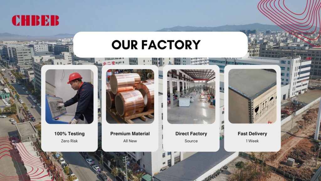
With over 60 years of transformer manufacturing expertise, CHBEB has established itself as one of China’s most trusted and globally recognized suppliers of dry type and oil-immersed distribution transformers. The company operates two factories in Wenzhou, one in Nanjing, and a technical and export office in Beijing, ensuring strong production capacity, engineering flexibility, and responsive customer service.
Why Global Buyers Choose CHBEB
- Certified Quality & Full Testing: Every transformer is manufactured under IEC 60076 / ISO 9001 standards and 100% factory-tested before shipment—no exceptions.
- 100% New Raw Materials: Premium copper, silicon steel, and insulation components; no recycled or downgraded materials.
- Fast-Track Delivery: Standard units ready in as little as 7 days for urgent EPC or retrofit projects.
- Customization & OEM Flexibility: Tailored voltage ratios, enclosure IP ratings, and cooling systems (AN/AF) to meet local grid and safety codes.
- Proven Reliability: Qualified supplier for the State Grid Corporation of China with a zero-accident operational record.
- Global Support: Experienced in export documentation, CE/CB certification, and on-site inspection support for clients in the Middle East, Africa, Southeast Asia, and CIS.
Whether you’re designing a hospital, data center, or renewable energy facility, CHBEB can provide a transformer that reduces installation complexity, minimizes lifetime cost, and ensures compliance with international standards.
👉 Looking for a partner who combines Chinese manufacturing strength with global engineering standards? Contact CHBEB for a tailored technical proposal or download our full catalog today.
Conclusion: Turning Technical Clarity into Strategic Advantage
Dry Type Distribution Transformers (DTDTs) stand as the future-ready solution for modern power systems where fire safety, regulatory compliance, and predictable operation are non-negotiable. They remove oil-handling risks, simplify infrastructure, and deliver steady performance under demanding environmental and urban conditions.
While oil-immersed transformers may appear cheaper at the purchase stage, a full Total Cost of Ownership (TCO) review tells a different story. The hidden costs of fire barriers, oil containment, environmental liability, and intensive maintenance often exceed the initial savings. In contrast, DTDTs combine lower operational risk, shorter installation time, and simplified compliance—a decisive advantage for EPC contractors, developers, and facility owners seeking predictable project outcomes.
Strategic transformer specification now depends on engineering foresight rather than price comparison alone:
- Model the total installed cost: Include auxiliary civil works, energy losses, and maintenance.
- Match insulation to environment: Choose Cast Resin for coastal or humid conditions, VPI for clean indoor sites.
- Verify standard alignment: Ensure thermal design matches the local climate—IEC (20 °C base) vs ANSI (30 °C base).
- Secure reliable testing and certification: Confirm IEC 60076 or IEEE compliance and full type-test reports.
For decision-makers overseeing critical infrastructure, DTDTs provide long-term stability, regulatory assurance, and lifecycle cost efficiency. Choosing the right manufacturer—one with verified engineering depth, certified production, and responsive after-sales support—turns this technology from a compliance measure into a long-term operational advantage.
Are you struggling to keep up with the rapid changes in the distribution transformer market driven by smart grid integration? You’re not alone. Many industry professionals find themselves overwhelmed by the new technologies and market shifts. But what if you could easily understand these changes and position yourself at the forefront of this growth wave?
Smart grid integration is reshaping the distribution transformer market by driving demand for intelligent, efficient, and communicative systems. As emerging markets adopt advanced grid technologies, brands like ABB, Siemens, and TBEA are leading innovation, enabling the next wave of energy infrastructure growth.
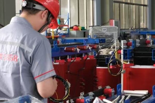
In this comprehensive guide, I’ll walk you through the key aspects of smart grid integration in the distribution transformer market. Whether you’re a manufacturer, utility professional, or industry analyst, this article will provide you with valuable insights to navigate this exciting phase of market growth.
What Is Smart Grid Integration and Why It Matters for Transformers?
Are you finding it challenging to grasp the concept of smart grid integration and its impact on distribution transformers? This technological shift is revolutionizing the power industry, but its implications can be complex. So, what exactly is smart grid integration, and why is it crucial for the future of distribution transformers?
Smart grid integration refers to the incorporation of advanced communication, monitoring, and control technologies into power distribution systems. For transformers, this means evolving from passive power conversion devices to active, intelligent nodes in the grid. Smart grid-ready transformers enable real-time monitoring, improved efficiency, and dynamic load management, crucial for modern power systems.
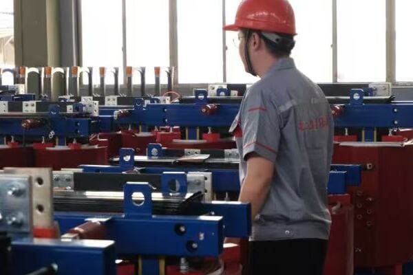
Understanding Smart Grid Integration for Transformers
Let’s break down the key aspects of smart grid integration:
- Bidirectional Power Flow
- Advanced Communication Capabilities
- Real-Time Monitoring and Diagnostics
- Automated Control and Response
Bidirectional Power Flow
Smart grids enable two-way power flow:
- Traditional grids: One-way flow from power plants to consumers
- Smart grids: Allow consumers to feed power back into the grid (e.g., from solar panels)
I recently worked on a project where we upgraded a residential area’s transformers to handle bidirectional power flow. This change allowed homeowners with solar panels to sell excess energy back to the grid, improving overall energy efficiency in the community.
Advanced Communication Capabilities
Smart transformers act as communication hubs:
- Integration with SCADA (Supervisory Control and Data Acquisition) systems
- Real-time data exchange with grid management systems
- Support for protocols like IEC 61850 for substation automation
During a recent smart city project, we implemented transformers with advanced communication modules. These units could seamlessly integrate with the city’s central grid management system, allowing for dynamic load balancing and rapid response to power quality issues.
Real-Time Monitoring and Diagnostics
Continuous monitoring enhances reliability:
- Temperature, load, and oil quality monitoring
- Predictive maintenance capabilities
- Early fault detection and alerts
Here’s a comparison of monitoring capabilities:
| Aspect | Traditional Transformer | Smart Grid Transformer |
|---|---|---|
| Monitoring Frequency | Periodic manual checks | Continuous real-time monitoring |
| Data Granularity | Limited parameters | Comprehensive data collection |
| Fault Detection | Reactive | Predictive and proactive |
| Maintenance Approach | Scheduled | Condition-based |
Automated Control and Response
Smart transformers can adapt to grid conditions:
- Automatic voltage regulation
- Load tap changing based on real-time demand
- Self-healing capabilities in case of minor faults
Key reasons why smart grid integration matters for transformers:
- Improved grid stability and reliability
- Enhanced energy efficiency and reduced losses
- Better integration of renewable energy sources
- Prolonged transformer lifespan through predictive maintenance
- Increased flexibility in power distribution management
In my experience, the transition to smart grid-ready transformers can be challenging but rewarding. I’ve seen utilities significantly reduce outage times and improve overall grid efficiency after implementing smart transformer technologies.
As we delve deeper into the specific features demanded by smart grids, keep in mind that this integration is not just about adding new technologies to transformers. It’s about reimagining the role of transformers in our power distribution systems, turning them from passive components into active, intelligent assets in our evolving energy landscape.
Key Features Smart Grids Demand from Modern Distribution Transformers?
Are you wondering what specific capabilities smart grids require from today’s distribution transformers? The evolution of power systems has led to new demands that traditional transformers simply can’t meet. But what exactly are these new features, and how do they contribute to a smarter, more efficient grid?
Smart grids demand advanced features from modern distribution transformers, including real-time monitoring capabilities, dynamic voltage regulation, enhanced overload capacity, and seamless communication integration. These features enable transformers to actively participate in grid management, improve power quality, and adapt to fluctuating energy demands and renewable energy inputs.
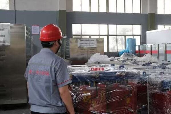
Essential Features for Smart Grid Transformers
Let’s explore the key features that smart grids demand from modern transformers:
- Advanced Monitoring and Diagnostics
- Dynamic Voltage Regulation
- Enhanced Overload Capacity
- Communication and Data Integration
- Cybersecurity Measures
Advanced Monitoring and Diagnostics
Smart transformers provide comprehensive real-time data:
- Continuous monitoring of temperature, load, and oil condition
- Advanced analytics for predictive maintenance
- Early fault detection and automated alerts
I recently worked on upgrading a substation with smart transformers. The new units’ ability to predict potential failures weeks in advance significantly reduced unplanned downtime and maintenance costs.
Dynamic Voltage Regulation
Adaptive voltage control is crucial for smart grids:
- Automatic tap changing based on real-time grid conditions
- Ability to handle voltage fluctuations from renewable sources
- Support for Volt/VAR optimization
During a recent project integrating a large solar farm into the grid, the smart transformers’ dynamic voltage regulation capabilities were essential in managing the intermittent nature of solar power input.
Enhanced Overload Capacity
Smart transformers offer improved flexibility:
- Ability to handle short-term overloads safely
- Dynamic rating based on real-time conditions
- Intelligent cooling systems for improved heat management
Here’s a comparison of overload capabilities:
| Aspect | Traditional Transformer | Smart Grid Transformer |
|---|---|---|
| Overload Capacity | Fixed rating | Dynamic rating |
| Cooling System | Passive or basic | Intelligent and adaptive |
| Overload Duration | Limited | Extended with active management |
| Heat Management | Basic monitoring | Advanced thermal modeling |
Communication and Data Integration
Seamless integration with grid management systems is essential:
- Support for multiple communication protocols (e.g., IEC 61850, DNP3)
- Real-time data exchange with SCADA systems
- Integration with advanced metering infrastructure (AMI)
In a recent smart city project, the transformers’ ability to communicate seamlessly with the central grid management system was crucial for implementing demand response programs and optimizing overall grid performance.
Cybersecurity Measures
With increased connectivity comes the need for robust security:
- Encrypted communication channels
- Access control and authentication mechanisms
- Regular security updates and patch management
Key considerations for smart grid transformer features:
- Assess the level of monitoring and diagnostics required for your specific grid needs
- Consider the voltage regulation capabilities necessary for your renewable energy integration plans
- Evaluate the overload capacity requirements based on your grid’s load profiles
- Ensure compatibility with your existing or planned grid communication systems
- Prioritize cybersecurity features to protect against potential threats
In my experience, the most successful smart grid implementations are those that carefully balance these advanced features with practical considerations like cost, maintenance requirements, and long-term scalability.
For instance, in a recent project for a mid-sized utility, we initially focused on implementing advanced monitoring and voltage regulation features. This phased approach allowed the utility to immediately improve grid efficiency while planning for future enhancements in communication and cybersecurity capabilities.
As we move forward to discuss emerging markets driving smart grid-ready transformer demand, keep in mind how these key features align with the specific needs and challenges of different regions and applications.
Emerging Markets Driving Smart Grid-Ready Transformer Demand?
Are you curious about where the next big opportunities for smart grid-ready transformers lie? The global landscape for smart grid adoption is rapidly evolving, with emerging markets playing an increasingly significant role. But which regions are leading this charge, and what factors are driving their demand for smart grid technologies?
Emerging markets, particularly in the Middle East, Latin America, and Southeast Asia, are driving significant demand for smart grid-ready transformers. Key drivers include rapid urbanization, renewable energy integration, and government initiatives for grid modernization. Projects like Saudi Arabia’s Vision 2030, Brazil’s smart meter rollout, and Singapore’s smart city initiatives are creating substantial opportunities for smart transformer deployments.

Analyzing Key Emerging Markets
Let’s explore the regions and factors driving smart grid transformer demand:
- Middle East: Focus on Smart Cities and Renewable Integration
- Latin America: Grid Modernization and Energy Efficiency
- Southeast Asia: Rapid Urbanization and Power Quality Improvement
- Africa: Expanding Access and Improving Reliability
Middle East: Focus on Smart Cities and Renewable Integration
The Middle East is investing heavily in smart infrastructure:
- Saudi Arabia’s Vision 2030 includes massive smart city projects
- UAE’s push for solar energy integration requires advanced grid management
- Qatar’s preparations for major events driving grid modernization
I recently consulted on a project for a smart city development in the UAE. The demand for smart transformers capable of handling bidirectional power flow and providing real-time data was unprecedented, driven by the integration of rooftop solar panels and electric vehicle charging stations.
Latin America: Grid Modernization and Energy Efficiency
Latin American countries are upgrading their aging grid infrastructure:
- Brazil’s smart meter rollout creating demand for compatible transformers
- Chile’s focus on renewable energy driving need for adaptive grid technologies
- Mexico’s energy reform opening opportunities for smart grid investments
During a recent visit to a utility in Brazil, I observed their efforts to implement smart transformers as part of a broader grid modernization program. The ability to remotely monitor and control these transformers was crucial for improving reliability in remote areas.
Southeast Asia: Rapid Urbanization and Power Quality Improvement
Southeast Asian nations are addressing urban growth challenges:
- Singapore’s smart nation initiative driving advanced grid technologies
- Indonesia’s archipelago geography creating unique smart grid challenges
- Vietnam’s industrial growth necessitating improved power quality and reliability
Here’s a comparison of smart grid initiatives in Southeast Asian countries:
| Country | Key Focus Area | Smart Transformer Application |
|---|---|---|
| Singapore | Smart City Infrastructure | Advanced monitoring and control |
| Indonesia | Island Grid Stability | Remote management and diagnostics |
| Vietnam | Industrial Power Quality | Voltage regulation and harmonics control |
| Malaysia | Renewable Integration | Adaptive load management |
Africa: Expanding Access and Improving Reliability
African nations are leveraging smart grid technologies to address fundamental challenges:
- Microgrid developments in rural areas requiring smart transformers
- Efforts to reduce technical losses in urban grids
- Increasing adoption of renewable energy sources necessitating flexible grid infrastructure
Key factors driving smart grid transformer demand in emerging markets:
- Government initiatives and regulations promoting grid modernization
- Rapid growth in renewable energy installations
- Need for improved energy efficiency and reduced losses
- Urbanization and the development of smart cities
- Efforts to improve grid reliability and reduce outages
In my experience, the demand for smart grid-ready transformers in these emerging markets often comes with unique challenges. For instance, during a project in Southeast Asia, we had to adapt smart transformer designs to withstand extreme humidity and flooding conditions, highlighting the need for region-specific solutions.
As we move to discuss how leading brands are adapting to the smart grid era, consider how these emerging market trends are shaping product development and market strategies for transformer manufacturers worldwide.
Leading Brands Adapting to the Smart Grid Era: ABB, Siemens, TBEA & More?
Are you wondering how major transformer manufacturers are responding to the smart grid revolution? The shift towards intelligent power systems is reshaping the competitive landscape. But how are industry leaders like ABB, Siemens, and TBEA adapting their products and strategies to meet the new demands of smart grids?
Leading brands like ABB, Siemens, and TBEA are at the forefront of smart grid transformer technology. ABB’s TXpert™ and Siemens’ Sensformer™ offer advanced IoT integration and real-time monitoring. TBEA is focusing on cost-effective smart solutions for emerging markets. These companies are investing heavily in R&D, developing products that support IEC 61850 standards, and offering comprehensive digital solutions for grid management.

Analyzing Leading Brands’ Smart Grid Strategies
Let’s explore how top manufacturers are adapting to smart grid requirements:
- ABB: Pioneering IoT Integration
- Siemens: Focus on Plug-and-Play Solutions
- TBEA: Cost-Effective Smart Solutions for Emerging Markets
- Schneider Electric: Emphasis on Energy Efficiency
- General Electric: Grid Analytics and Asset Performance Management
ABB: Pioneering IoT Integration
ABB is leading with its TXpert™ ecosystem:
- Advanced sensors and monitoring capabilities
- Cloud-based analytics for predictive maintenance
- Compatibility with ABB Ability™ digital platform
I recently visited an ABB smart transformer installation at a major utility. The level of detail in real-time monitoring and the predictive maintenance capabilities were impressive, significantly reducing the utility’s operational costs.
Siemens: Focus on Plug-and-Play Solutions
Siemens’ Sensformer™ line emphasizes ease of integration:
- Built-in connectivity for immediate grid integration
- Comprehensive digital twin capabilities
- Focus on cybersecurity in grid communications
During a recent project, we implemented Siemens Sensformers™ in a large industrial complex. The plug-and-play nature of these units significantly reduced installation time and simplified integration with the existing SCADA system.
TBEA: Cost-Effective Smart Solutions for Emerging Markets
TBEA is adapting smart technologies for price-sensitive markets:
- Focus on essential smart features at competitive prices
- Customizable solutions for specific market needs
- Strong presence in Belt and Road Initiative countries
Here’s a comparison of smart features offered by these leading brands:
| Feature | ABB | Siemens | TBEA |
|---|---|---|---|
| IoT Integration | Advanced | Comprehensive | Basic to Moderate |
| Analytics Platform | Cloud-based | Edge and Cloud | Primarily Edge-based |
| Market Focus | Global High-End | Global Diverse | Emerging Markets |
| Customization Level | High | Moderate | High |
Schneider Electric: Emphasis on Energy Efficiency
Schneider is focusing on smart transformers for energy optimization:
- Integration with EcoStruxure™ power management platform
- Advanced voltage regulation for energy loss reduction
- Solutions tailored for commercial and light industrial applications
General Electric: Grid Analytics and Asset Performance Management
GE is leveraging its digital expertise for smart grid solutions:
- Focus on grid-wide analytics and optimization
- Integration with Predix™ platform for asset performance management
- Emphasis on modernizing existing transformer fleets with smart capabilities
Key strategies adopted by leading brands:
- Heavy investment in R&D for smart grid technologies
- Development of comprehensive digital ecosystems beyond just hardware
- Focus on cybersecurity as a key component of smart grid offerings
- Tailoring solutions for different market segments and regions
- Emphasis on ease of integration with existing grid infrastructure
In my experience, the success of these brands in the smart grid era often comes down to their ability to provide not just smart products, but comprehensive solutions. For instance, during a recent grid modernization project, ABB’s ability to offer end-to-end solutions from transformers to grid management software was a key factor in their selection.
As we move to discuss real-world applications of smart grid transformers, consider how these brand strategies are translating into practical solutions for utilities and industrial customers worldwide.
Real-World Projects: Smart Grid Transformer Applications in Action?
Are you curious about how smart grid transformers are being implemented in actual projects around the world? Understanding real-world applications can provide valuable insights into the practical benefits and challenges of this technology. But what specific projects showcase the true potential of smart grid transformers, and what lessons can we learn from them?
Smart grid transformers are being deployed in diverse projects globally. Notable examples include ABB’s involvement in Saudi Arabia’s NEOM city, Siemens’ smart transformer installations in German digital substations, and TBEA’s contributions to grid modernization in Central Asian countries. These projects demonstrate improved grid efficiency, better integration of renewable energy, and enhanced reliability through real-time monitoring and control.
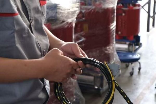
Exploring Smart Grid Transformer Projects
Let’s examine some key projects showcasing smart grid transformer applications:
- NEOM Smart City Project (Saudi Arabia)
- Digital Substation Upgrade (Germany)
- Renewable Energy Integration (Chile)
- Urban Grid Modernization (Singapore)
- Rural Electrification with Smart Microgrids (India)
NEOM Smart City Project (Saudi Arabia)
ABB’s smart transformers are playing a crucial role in Saudi Arabia’s futuristic NEOM city:
- Implementation of advanced distribution management system
- Real-time monitoring and control of power distribution
- Integration with renewable energy sources and energy storage systems
I had the opportunity to consult on the early stages of the NEOM project. The scale of smart transformer deployment was unprecedented, with each unit acting as a node in a vast, interconnected energy network. This project is setting new standards for smart city power infrastructure.
Digital Substation Upgrade (Germany)
Siemens has been instrumental in upgrading German substations with smart transformer technology:
- Deployment of Sensformer™ units for enhanced grid visibility
- Implementation of IEC 61850-compliant communication systems
- Integration with advanced grid analytics platforms
During a recent visit to one of these upgraded substations, I was impressed by the seamless integration of smart transformers with the existing grid infrastructure. The ability to remotely monitor and control these units has significantly improved response times to potential issues.
Renewable Energy Integration (Chile)
TBEA’s smart transformers are supporting Chile’s ambitious renewable energy goals:
- Smart transformers managing variable inputs from solar and wind farms
- Advanced voltage regulation to maintain grid stability
- Real-time data analytics for optimizing energy distribution
Here’s a comparison of project outcomes in different applications:
| Project Type | Key Benefits | Challenges Addressed |
|---|---|---|
| Smart City (NEOM) | Comprehensive energy management | Complex integration of multiple systems |
| Digital Substation | Enhanced grid visibility and control | Upgrading legacy infrastructure |
| Renewable Integration | Improved grid stability | Managing intermittent power sources |
| Urban Modernization | Reduced outages and energy losses | High-density power distribution |
| Rural Electrification | Expanded access to reliable power | Remote monitoring and maintenance |
Urban Grid Modernization (Singapore)
Schneider Electric’s smart transformers are central to Singapore’s smart nation initiative:
- Deployment of IoT-enabled transformers in urban substations
- Implementation of advanced demand response capabilities
- Integration with Singapore’s broader smart city infrastructure
Rural Electrification with Smart Microgrids (India)
GE’s smart transformer solutions are supporting rural electrification efforts in India:
- Implementation of smart microgrids in remote villages
- Use of solar-plus-storage systems with smart transformers
- Remote monitoring and management capabilities for improved reliability
Key lessons from these real-world projects:
- Importance of scalable and flexible smart transformer solutions
- Critical role of data analytics in maximizing grid efficiency
- Need for robust cybersecurity measures in all smart grid deployments
- Value of integrating smart transformers with broader energy management systems
- Importance of customizing solutions for specific regional and application needs
In my experience, the success of these projects often hinges on the ability to adapt smart transformer technologies to local conditions and requirements. For instance, in the Chilean renewable energy project, the smart transformers had to be specially configured to handle the extreme temperature variations and high-altitude conditions of the Atacama Desert.
These real-world applications demonstrate that smart grid transformers are not just theoretical concepts but practical solutions driving significant improvements in grid performance, reliability, and efficiency across diverse global contexts.
As we look towards the future of smart grid transformer technology, these projects provide valuable insights into the direction of industry innovation and the potential for transformative impact on power systems worldwide.
Future Outlook: Innovations Shaping the Next Growth Phase?
Are you wondering what’s next on the horizon for smart grid transformer technology? The rapid pace of innovation in this field can be both exciting and overwhelming. But what key developments should you be watching, and how might they shape the future of power distribution systems?
The future of smart grid transformers is being shaped by innovations like solid-state transformer technology, AI-driven predictive maintenance, edge computing for real-time decision making, and advanced materials for improved efficiency. These developments promise to enhance grid flexibility, reliability, and integration with renewable energy sources, driving the next phase of growth in the smart grid transformer market.

Exploring Future Innovations in Smart Grid Transformers
Let’s examine the key innovations that are likely to drive the next growth phase:
- Solid-State Transformer (SST) Technology
- AI and Machine Learning Integration
- Edge Computing and Distributed Intelligence
- Advanced Materials and Nanotechnology
- Enhanced Cybersecurity Measures
Solid-State Transformer (SST) Technology
SSTs represent a paradigm shift in transformer design:
- Use of power electronics for more flexible voltage conversion
- Improved power quality and harmonics control
- Potential for significant size and weight reduction
I recently attended a demonstration of SST technology at a research facility. The ability of these units to handle rapid voltage fluctuations and provide precise power quality control was impressive, suggesting significant potential for renewable energy integration and microgrid applications.
AI and Machine Learning Integration
AI is set to revolutionize transformer management:
- Advanced predictive maintenance algorithms
- Real-time optimization of grid operations
- Automated fault detection and self-healing capabilities
During a recent project, we implemented an AI-driven monitoring system for a fleet of smart transformers. The system’s ability to predict potential failures weeks in advance and suggest optimal maintenance schedules led to a 30% reduction in unplanned downtime.
Edge Computing and Distributed Intelligence
Edge computing is enhancing transformer responsiveness:
- Local processing of data for faster decision-making
- Reduced reliance on central control systems
- Improved resilience and autonomy of grid nodes
Here’s a comparison of current vs. future smart transformer capabilities:
| Aspect | Current Technology | Future Innovation |
|---|---|---|
| Voltage Conversion | Traditional windings | Solid-state electronics |
| Data Processing | Centralized | Edge computing |
| Maintenance | Scheduled/Reactive | AI-driven Predictive |
| Grid Integration | Passive/Semi-active | Fully active/Autonomous |
| Cybersecurity | Basic encryption | Quantum-resistant protocols |
Advanced Materials and Nanotechnology
New materials are improving transformer efficiency:
- Nanocrystalline core materials for reduced losses
- Advanced insulation for improved thermal management
- Superconducting materials for high-capacity applications
Enhanced Cybersecurity Measures
As transformers become more connected, security is paramount:
- Development of quantum-resistant encryption
- Blockchain technology for secure data transmission
- AI-powered threat detection and response systems
Key trends shaping the future of smart grid transformers:
- Increasing integration of renewable energy and energy storage systems
- Growing demand for more flexible and resilient grid architectures
- Emphasis on sustainability and environmental impact reduction
- Rising importance of data analytics and real-time decision making
- Continued focus on improving energy efficiency and reducing losses
In my experience, the most successful innovations in this field are those that address multiple challenges simultaneously. For instance, solid-state transformers not only offer improved power quality but also enable better integration of renewable sources and enhance grid flexibility.
As we look to the future, it’s clear that smart grid transformers will play an increasingly central role in our power systems. The innovations we’re seeing today are laying the groundwork for more efficient, reliable, and sustainable energy distribution networks of tomorrow.
Conclusion
Smart grid integration is driving significant growth and innovation in the distribution transformer market. From advanced monitoring capabilities to AI-driven predictive maintenance, these technologies are reshaping power systems worldwide. As emerging markets embrace smart grid solutions and leading brands continue to innovate, the future of distribution transformers looks increasingly intelligent, efficient, and adaptable to our evolving energy needs.
Remember, at chbeb-ele, we’re not just sharing information – we’re empowering you to be part of the solution in creating a secure, clean, and efficient energy future. Let’s continue this journey together.
Choosing the right distribution transformer manufacturers can be overwhelming. Prices, delivery times, and technical capabilities vary widely across brands. This guide compares global leaders and regional champions on technology, production capacity, and logistics so you can balance quality, cost, and reliability for 2025 projects—and pick a partner that matches your standards, budget, and timeline.
Top 10 Distribution Transformer Manufacturers
This article compares the top 10 distribution transformer manufacturers, including global leaders like ABB and Siemens, and regional champions such as TBEA and CHBEB. We analyze their strengths in technology, production capacity, and delivery capabilities. This comparison helps buyers make informed decisions based on project requirements, budget constraints, and regional preferences in 2025.
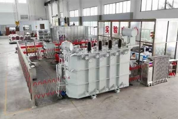
In this comprehensive guide, I’ll walk you through the leading global and regional manufacturers in the distribution transformer market. Whether you’re sourcing for a utility-scale project, industrial application, or commercial installation, this article will provide you with valuable insights to select the best partner for your specific needs.
Global Leaders: ABB, Siemens Energy, Schneider, Eaton, GE
Are you wondering which companies dominate the global distribution transformer market? Understanding the strengths of these industry giants can significantly impact your procurement decisions. But what sets these global leaders apart, and how do they compare to each other?
The global distribution transformer1 market is led by companies like ABB, Siemens Energy, Schneider Electric, Eaton, and GE Grid Solutions. These manufacturers are known for their advanced technologies, wide product ranges, and global presence. They excel in areas such as energy efficiency, smart grid compatibility, and innovative designs that cater to diverse international standards and requirements.
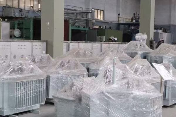
Global Distribution Transformer Leaders
Analyzing Global Market Leaders
Let’s explore the key players in the global distribution transformer market:
- ABB
- Siemens Energy
- Schneider Electric
- Eaton
- GE Grid Solutions
ABB — Digital Integration & Renewables
ABB is a frontrunner in distribution transformer technology:
- Wide range of oil-immersed and dry-type transformers
- Focus on energy efficiency and digital solutions
- Strong presence in renewable energy and smart grid applications
I recently worked on a project where ABB’s smart transformers were crucial in integrating a large solar farm into the existing grid. Their ability to handle bidirectional power flow and provide real-time monitoring was impressive.
Siemens Energy — Ester Fluids & Low-Noise Urban Designs
Siemens Energy is known for its innovative approaches:
- Specializes in medium-voltage distribution transformers
- Emphasis on environmentally friendly designs
- Strong R&D in areas like ester fluids and amorphous core technology
During a recent urban substation upgrade, we chose Siemens Energy transformers for their compact design and low noise levels, which were perfect for the densely populated area.
Schneider Electric — Sustainability & TCO
Schneider Electric focuses on sustainability and efficiency:
- Leader in eco-designed transformers
- Strong in commercial and industrial applications
- Emphasis on total cost of ownership optimization
Here’s a quick comparison of these global leaders:
| Brand | Key Strength | Typical Applications |
|---|---|---|
| ABB | Digital integration | Utility, Renewables |
| Siemens Energy | Innovation in materials | Industrial, Urban |
| Schneider Electric | Sustainability | Commercial, Data Centers |
| Eaton | Reliability | Critical Infrastructure |
| GE Grid Solutions | Grid modernization | Utility, Smart Cities |
Eaton — Reliability for Critical InfrastructureEaton — Reliability for Critical Infrastructure
Eaton excels in reliability and customization:
- Strong in both liquid-filled and dry-type transformers
- Focus on critical power applications
- Known for robust designs and long service life
I recall a data center project where Eaton’s transformers were selected for their exceptional reliability and after-sales support, crucial factors for such critical infrastructure.
GE Grid Solutions — Grid Modernization & Smart Cities
GE Grid Solutions is a leader in grid modernization:
- Expertise in large power transformers and distribution solutions
- Strong focus on smart grid technologies
- Emphasis on grid resilience and efficiency
Key considerations when evaluating global market leaders:
- Assess their technological innovations and how they align with your project needs
- Consider their global presence and ability to provide local support
- Evaluate their experience in your specific industry or application
- Look at their sustainability initiatives and how they align with your corporate goals
- Consider the total cost of ownership, including efficiency and maintenance costs
In my experience, these global leaders often provide cutting-edge solutions but may come at a premium price. I’ve seen projects where the initial higher cost was justified by long-term energy savings and reduced maintenance needs.
As we move forward to discuss regional champions, keep in mind that while these global leaders offer extensive capabilities, regional manufacturers can sometimes provide more tailored solutions or better pricing for specific markets.
Regional Champions Making an Impact?
Are you curious about the regional players that are challenging the global giants in the distribution transformer market? These companies are making significant strides in their local markets and beyond. But what makes them stand out, and how are they competing on the global stage?
Regional champions in the distribution transformer market include TBEA and CHBEB from China, Howard Industries from the USA, Wilson Transformers from Australia, and Crompton Greaves from India. These manufacturers often excel in areas like cost-effectiveness, local market knowledge, and customization for specific regional needs. They are increasingly expanding their global footprint, especially in emerging markets.
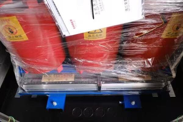
Regional Transformer Manufacturers’ Global Reach
Regional Champions: TBEA, CHBEB, Howard, Wilson, CG
Let’s examine some key regional players making waves in the distribution transformer market:
- TBEA (China)
- CHBEB (China)
- Howard Industries (USA)
- Wilson Transformers (Australia)
- Crompton Greaves (India)
TBEA — Large-Scale Capacity & BRI Projects
TBEA is a major player in the Asian market:
- Large-scale production capabilities
- Strong presence in Belt and Road Initiative projects
- Competitive pricing for high-capacity transformers
I recently visited a TBEA factory and was impressed by their advanced manufacturing processes and quality control measures. Their ability to produce large quantities of transformers efficiently gives them a significant advantage in large-scale projects.
CHBEB — Customization & Fast Delivery for Emerging Markets
CHBEB is recognized as one of China’s regional champions in the distribution transformer industry.
- Customization Strength: CHBEB specializes in adapting transformer designs for non-standard voltages, project-specific grid codes, and customer-driven requirements.
- Fast Turnaround: The company is known for rapid production and delivery cycles, supporting projects with strict deadlines in emerging markets.
- Regional Growth: With a growing footprint in Southeast Asia, the Middle East, and Africa, CHBEB is increasingly chosen by EPCs and utilities looking for reliable yet cost-effective alternatives.
Case Example: In a recent Southeast Asian utility project, CHBEB supplied distribution transformers tailored to the local 11/22kV requirements. The ability to deliver within 30 days helped the client commission the substation on schedule, avoiding costly delays.
Howard Industries — ANSI Compliance for Utilities
Howard Industries is a key player in the North American market:
- Focus on meeting ANSI standards
- Strong in utility and industrial applications
- Known for reliability and after-sales support
Here’s a comparison of these regional champions:
| Brand | Key Strength | Primary Markets |
|---|---|---|
| TBEA | Large-scale production | Asia, Africa |
| CHBEB | Customization | Emerging markets |
| Howard Industries | ANSI compliance | North America |
| Wilson Transformers | Energy efficiency | Australia, Southeast Asia |
| Crompton Greaves | Cost-effectiveness | India, Middle East |
Wilson Transformers — Energy-Efficient Designs
Wilson Transformers excels in energy-efficient designs:
- Leader in Australian and New Zealand markets
- Focus on low-loss transformer technology
- Growing exports to Southeast Asian countries
I worked on a project in Australia where Wilson’s transformers were chosen for their compliance with local energy efficiency standards and their ability to handle the harsh environmental conditions of the outback.
Crompton Greaves — Value Engineering & Cost-Effectiveness
Crompton Greaves is known for its cost-effective solutions:
- Strong presence in Indian and Middle Eastern markets
- Wide range of distribution transformers
- Focus on value engineering for emerging markets
Key considerations when evaluating regional champions:
- Assess their understanding of local standards and regulations
- Consider their production capacity and ability to meet project timelines
- Evaluate their export experience and global support capabilities
- Look at their R&D investments and technological advancements
- Consider their pricing strategy and how it fits with your budget constraints
In my experience, these regional champions often offer a great balance of quality and cost-effectiveness. I’ve seen projects where choosing a regional manufacturer led to significant cost savings without compromising on quality or performance.
As we move forward to compare global and regional manufacturers, keep in mind that the choice between them often depends on specific project requirements, budget constraints, and the importance of local support and customization.
Global vs. Regional: Which Fits Your Project?
Are you finding it challenging to weigh the pros and cons of global versus regional distribution transformer manufacturers? This comparison is crucial for making informed procurement decisions. But how do these different types of manufacturers stack up against each other in key areas?
Global manufacturers like ABB and Siemens often lead in technology and have extensive international experience. Regional champions like TBEA and CHBEB excel in cost-effectiveness and local market knowledge. Global brands typically offer advanced features and worldwide support, while regional manufacturers provide faster customization and often better pricing. The choice depends on project specifics, budget, and required technological sophistication.

Global vs Regional Manufacturer Comparison
Analyzing Global vs Regional Manufacturers
Let’s break down the key differences between global and regional manufacturers:
- Technological Capabilities
- Market Presence and Support
- Customization and Flexibility
- Pricing and Cost-Effectiveness
- Compliance and Certifications
Technology & Standards Compliance: What Buyers Should Know
Global and regional manufacturers often differ in their technological offerings:
- Global: Often lead in cutting-edge technologies and innovations
- Regional: Focus on adapting technologies to local needs and conditions
I once worked on a smart grid project where we chose a global manufacturer for their advanced IoT integration capabilities, which weren’t available from regional suppliers at the time.
Market Presence and After-Sales Support Compared
The scope and nature of market presence vary:
- Global: Worldwide presence with standardized support systems
- Regional: Strong local presence with personalized support
Here’s a comparison table of market presence and support:
| Aspect | Global Manufacturers | Regional Manufacturers |
|---|---|---|
| Geographic Reach | Worldwide | Focused on specific regions |
| Local Knowledge | Broad but sometimes generalized | Deep understanding of local markets |
| After-Sales Support | Standardized global processes | Often more personalized and responsive |
| Spare Parts Availability | Wide network, but can be slower | Usually faster local availability |
Customization, Lead Time & Local Support: Why It Matters
Ability to tailor products to specific needs differs:
- Global: Standardized product lines with some customization options
- Regional: Often more flexible in adapting to unique local requirements
During a recent project in a developing country, we opted for a regional manufacturer due to their willingness to modify designs to meet specific local grid conditions, which global manufacturers were less flexible about.
Price vs. Total Cost of Ownership: Which Is Better Value?
Pricing strategies and cost structures vary:
- Global: Often premium pricing, justified by brand value and advanced features
- Regional: Generally more competitive pricing, especially in their home markets
Key considerations for comparing global and regional manufacturers:
- Assess the level of technological sophistication required for your project
- Consider the importance of local support and market understanding
- Evaluate the need for customization versus standardized solutions
- Analyze the total cost of ownership, not just initial purchase price
- Consider long-term factors like reliability, efficiency, and upgrade potential
In my experience, the choice between global and regional manufacturers often comes down to a balance of factors. I’ve seen projects where the advanced features of global brands were crucial for success, and others where the cost-effectiveness and local knowledge of regional manufacturers were more valuable.
As we continue to explore what sets these brands apart, remember that the best choice depends on your specific project requirements, budget constraints, and long-term operational needs.
What Really Sets Brands Apart: Tech, Capacity, Delivery
Are you wondering what truly differentiates top distribution transformer manufacturers from each other? Understanding these distinctions is crucial for making the right choice for your project. But what specific factors in technology, production capacity, and delivery capabilities set these brands apart?
Leading transformer brands differentiate themselves through technological innovations, production capacities, and delivery capabilities. Global leaders often excel in advanced technologies like smart grid integration and energy efficiency. Regional champions typically offer advantages in production flexibility and faster delivery times. Key differentiators include R&D investments, manufacturing scale, customization abilities, and supply chain efficiencies.
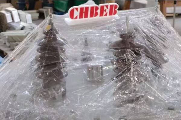
Transformer Manufacturer Differentiators
Analyzing Key Differentiating Factors
Let’s explore what sets these brands apart in three crucial areas:
- Technological Innovations
- Production Capacity and Scalability
- Delivery and Supply Chain Efficiency
Technological Innovations: How R&D Shapes Competitive Advantage
Innovation is a key differentiator among manufacturers:
- Advanced materials (e.g., amorphous core technology)
- Smart features (e.g., IoT integration, real-time monitoring)
- Energy efficiency improvements
I recently worked on a project where we chose a manufacturer specifically for their advanced ester-based insulation technology, which offered superior fire safety and environmental benefits compared to traditional mineral oil.
Production Scale, Automation & Quality Control: Why It Matters
Manufacturing capabilities vary significantly:
- Large-scale production vs. specialized manufacturing
- Automation levels and quality control processes
- Ability to scale production for large projects
Here’s a comparison of production capabilities:
| Aspect | Global Leaders | Regional Champions |
|---|---|---|
| Production Scale | Very large, often global | Medium to large, often regional |
| Automation Level | Highly automated | Varies, often balancing automation and labor |
| Customization Ability | Standardized with some customization | Often more flexible for customization |
| Quality Control | Rigorous, standardized processes | Varies, often with strong local adaptations |
Delivery and Supply Chain Efficiency: What Buyers Should Compare
Delivery capabilities can be a crucial differentiator:
- Global vs. regional supply chain networks
- Lead times and on-time delivery performance
- Flexibility in order sizes and specifications
During a time-critical project in Southeast Asia, we opted for a regional manufacturer due to their ability to deliver custom transformers in half the time quoted by global competitors, which was crucial for meeting our project deadlines.
Key factors that set brands apart:
- R&D investment and pace of innovation
- Manufacturing technology and process efficiency
- Customization capabilities and flexibility
- Global vs. regional supply chain strengths
- After-sales support and service network
In my experience, the true differentiators often become apparent in challenging situations. I’ve seen cases where a manufacturer’s ability to quickly adapt to unexpected project changes or their robust after-sales support made a significant difference in project outcomes.
For instance, during a recent renewable energy project, a global manufacturer’s advanced load management technology proved crucial in handling the variable output from wind turbines, significantly improving grid stability.
As we move towards discussing how to choose the right partner, keep in mind that these differentiating factors should be weighed against your specific project requirements and operational context.
Choosing the Right Partner: What to Consider in 2025?
Are you feeling overwhelmed by the options available when selecting a distribution transformer manufacturer for your 2025 projects? Making the right choice is crucial for project success, but what factors should you prioritize in this rapidly evolving industry landscape?
When choosing a distribution transformer partner in 2025, consider factors like technological advancements in smart grid compatibility and energy efficiency. Evaluate manufacturers’ sustainability practices, digital integration capabilities, and adaptability to renewable energy trends. Also, assess their global vs. local presence, customization abilities, and long-term support. The right partner should align with your project’s specific needs, budget constraints, and future scalability requirements.
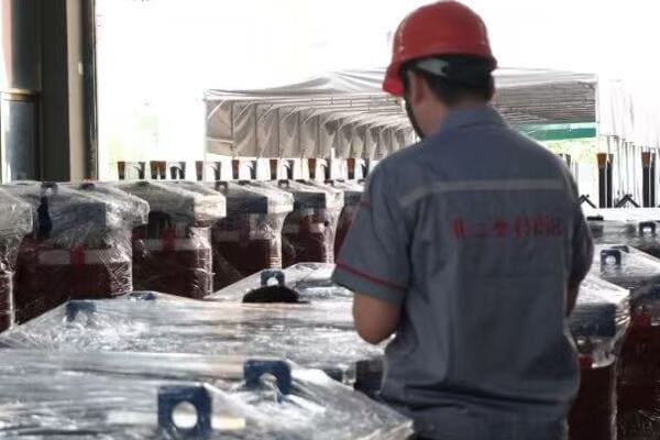
Transformer Manufacturer Selection Process
Key Considerations for Choosing a Transformer Partner
Let’s explore the crucial factors to consider when selecting a manufacturer:
- Technological Alignment with Future Trends
- Sustainability and Environmental Impact
- Customization and Flexibility
- Global vs. Local Support
- Total Cost of Ownership
Technological Alignment with Future Trends: How to Future-Proof Your Project
Ensure the manufacturer’s technology roadmap aligns with industry trends:
- Smart grid compatibility and IoT integration
- Advanced materials for improved efficiency
- Adaptability to renewable energy integration
I recently advised a client to choose a manufacturer with advanced digital twin capabilities for their transformers. This technology allowed for predictive maintenance and optimized performance, crucial for their smart city project.
Sustainability and Environmental Impact
Environmental considerations are increasingly important:
- Use of eco-friendly materials and processes
- Energy efficiency ratings and lifecycle assessments
- Compliance with future environmental regulations
Here’s a comparison of sustainability factors:
| Factor | Traditional Approach | Future-Focused Approach |
|---|---|---|
| Insulation | Mineral oil | Biodegradable esters |
| Core Material | Silicon steel | Amorphous metals |
| Efficiency Standards | Meets current standards | Exceeds future projections |
| Recyclability | Basic | Comprehensive end-of-life management |
Customization and Flexibility: What to Expect from Your Supplier
Ability to adapt to specific project needs is crucial:
- Tailoring designs to unique specifications
- Flexibility in production schedules
- Capacity to handle both standard and non-standard requirements
During a recent project in a remote area with extreme weather conditions, we chose a manufacturer known for their willingness to customize. They modified their standard design to include enhanced cooling and insulation, which was crucial for the transformer’s longevity in that harsh environment.
Global vs. Local Support: How to Balance Expertise and Presence
Consider the balance between global expertise and local presence:
- Availability of local technical support
- Speed of spare parts delivery
- Understanding of local regulations and standards
I once worked on a project where we initially chose a global manufacturer for their advanced technology. However, we faced significant delays due to lack of local support. In subsequent phases, we switched to a manufacturer with a strong local presence, which greatly improved our project efficiency.
Total Cost of Ownership: What Buyers Should Calculate
Look beyond the initial purchase price:
- Energy efficiency and operational costs
- Maintenance requirements and costs
- Expected lifespan and reliability
Key considerations for choosing the right partner in 2025:
- Assess the manufacturer’s investment in R&D and future technologies
- Evaluate their commitment to sustainability and environmental responsibility
- Consider their ability to provide customized solutions for your specific needs
- Weigh the benefits of global expertise against the advantages of local support
- Calculate the total cost of ownership over the transformer’s expected lifespan
In my experience, the best choice often comes from balancing these factors based on your project’s specific requirements. I’ve seen cases where paying a premium for a more technologically advanced transformer resulted in significant long-term savings through improved efficiency and reduced maintenance needs.
For example, in a recent grid modernization project, we chose a manufacturer that offered slightly higher upfront costs but provided advanced remote monitoring capabilities. This feature allowed for predictive maintenance, significantly reducing downtime and operational costs over the life of the transformers.
As we move to discuss transformer supplier trends to watch in 2025, keep in mind that the ideal partner should not only meet your current needs but also be well-positioned to adapt to future industry developments.
Distribution Transformer Supplier Trends to Watch in 2025?
Are you wondering how the distribution transformer market will evolve by 2025? Staying ahead of industry trends is crucial for making informed decisions about your power infrastructure. But what key developments should you be watching, and how might they impact your choice of transformer suppliers?
Key trends in the distribution transformer market for 2025 include increased focus on smart grid compatibility, adoption of eco-friendly materials, integration of AI for predictive maintenance, and advancements in energy efficiency. Suppliers are also moving towards modular designs for easier upgrades and exploring new materials like high-temperature superconductors. These trends are reshaping product offerings and supplier strategies.

2025 Transformer Market Trends
Analyzing Key Trends in the Transformer Market
Let’s explore the major trends shaping the distribution transformer industry:
- Smart Grid Integration and IoT Connectivity
- Eco-Friendly and Sustainable Designs
- AI and Predictive Maintenance
- Modular and Scalable Solutions
- Advanced Materials and Efficiency Improvements
Smart Grid Integration and IoT Connectivity: How Transformers Are Getting Smarter
Transformers are becoming key nodes in smart grid networks:
- Real-time monitoring and data analytics capabilities
- Enhanced grid stability and load management features
- Cybersecurity considerations in transformer design
I recently worked on a project where we implemented smart transformers with advanced IoT capabilities. These units provided real-time data on power quality and usage patterns, allowing for dynamic load balancing and significantly improving overall grid efficiency.
Eco-Friendly and Sustainable Designs: Why Green Matters in 2025
Sustainability is becoming a core focus:
- Increased use of biodegradable insulating fluids
- Designs optimized for recyclability and reduced environmental impact
- Focus on reducing carbon footprint in manufacturing processes
Here’s a comparison of traditional vs. eco-friendly approaches:
| Aspect | Traditional Approach | Eco-Friendly Approach |
|---|---|---|
| Insulation | Mineral oil | Natural esters or synthetic esters |
| Core Material | Conventional silicon steel | Amorphous metals or high-grade silicon steel |
| Cooling System | Forced air or oil | Natural cooling or biodegradable coolants |
| End-of-Life | Limited recyclability | Designed for easy recycling and material recovery |
AI and Predictive Maintenance: What Buyers Should Expect
Artificial Intelligence is revolutionizing transformer maintenance:
- AI-driven predictive maintenance to prevent failures
- Machine learning algorithms for optimizing performance
- Integration with broader asset management systems
During a recent utility modernization project, we implemented AI-enabled transformers that could predict potential failures weeks in advance. This capability significantly reduced unplanned downtime and maintenance costs.
Modular and Scalable Solutions: How Suppliers Deliver Flexibility
Flexibility in design and deployment is becoming crucial:
- Modular transformer designs for easier upgrades and replacements
- Scalable solutions to accommodate growing power needs
- Plug-and-play components for faster installation and commissioning
Key trends to watch in the transformer market:
- Increased adoption of digital twin technology for lifecycle management
- Development of hybrid transformers combining different voltage technologies
- Integration of energy storage capabilities within transformer units
- Enhanced focus on cybersecurity features in smart transformers
- Exploration of new materials like high-temperature superconductors
In my experience, staying ahead of these trends can provide significant advantages in both performance and cost-effectiveness. I’ve seen projects where early adoption of trends like AI-driven maintenance or eco-friendly designs led to substantial long-term benefits, including reduced operational costs and improved regulatory compliance.
For instance, a forward-thinking utility company I worked with invested in modular, easily upgradable transformers. This decision initially seemed costly, but it paid off when they were able to quickly adapt to new smart grid requirements without replacing entire units.
As we conclude our exploration of the distribution transformer market, remember that these trends will likely shape the industry’s future. Suppliers who are at the forefront of these developments may offer significant advantages in terms of future-proofing your power infrastructure investments.
Conclusion
Choosing the right distribution transformer manufacturer is crucial for project success. Global leaders offer advanced technology and worldwide support, while regional champions excel in cost-effectiveness and local knowledge. Consider factors like smart grid compatibility, sustainability, and total cost of ownership when making your decision. Stay informed about emerging trends to ensure your choice aligns with future industry developments.
Remember, at chbeb-ele, we’re not just sharing information – we’re empowering you to be part of the solution in creating a secure, clean, and efficient energy future. Let’s continue this journey together.
Want to compare more transformer options and technical details?
Download our full transformer catalog here or reach out to CHBEB for a personalized quotation.
Are you struggling to understand the complex cost factors affecting the transformer market in 2025? You’re not alone. Many buyers and manufacturers find themselves confused by the rapidly changing landscape of raw material prices, logistics challenges, and supply chain pressures. But what if you could easily grasp these factors to make more informed decisions and potentially save millions on your transformer purchases?
Distribution transformer costs in 2025 are driven by raw material price fluctuations, rising logistics fees, and global supply chain pressures. Copper, silicon steel, and oil remain key cost components. Understanding these factors helps buyers make informed procurement decisions and plan for price volatility.
In this comprehensive guide, I’ll walk you through the crucial factors influencing transformer costs in 2025. Whether you’re a procurement manager, a transformer manufacturer, or an industry analyst, this article will provide you with valuable insights to navigate the complex world of transformer pricing and make strategic decisions.
Overview of 2025 Distribution Transformer Cost Drivers?
Are you finding it challenging to keep up with the ever-changing cost factors in the transformer market? The landscape of transformer pricing in 2025 is more complex than ever. But what are the key drivers behind these costs, and how can understanding them help you in your procurement or manufacturing strategies?
The 2025 distribution transformer market is influenced by global demand fluctuations, supply chain constraints, and regional market dynamics. Key cost drivers include raw material prices (especially copper and steel), energy costs, labor expenses, and logistics fees. Understanding these factors is crucial for accurate budgeting, strategic sourcing, and effective price negotiations in the transformer industry.
Diving Deeper into 2025 Cost Drivers
Let’s explore the key factors influencing transformer costs:
- Global Demand & Supply Chain Constraints
- Market-Specific Factors (USA, China, Middle East)
- Short-Term vs Long-Term Procurement Planning
Global Demand & Supply Chain Constraints
The global transformer market in 2025 is shaped by:
- Increasing demand from renewable energy projects
- Ongoing supply chain disruptions from post-pandemic recovery
- Geopolitical tensions affecting material sourcing
I recently worked on a large-scale wind farm project where transformer delivery times were extended by months due to global supply chain issues. This delay highlighted the importance of understanding and planning for these constraints in project timelines.
Market-Specific Factors (USA, China, Middle East)
Different regions face unique challenges:
- USA: Focus on grid modernization and renewable integration
- China: Balancing domestic demand with export market pressures
- Middle East: Large infrastructure projects driving demand
Here’s a comparison of market factors:
| Factor | USA | China | Middle East |
|---|---|---|---|
| Primary Demand Driver | Grid upgrades | Industrial growth | Infrastructure projects |
| Raw Material Sourcing | Mixed domestic/import | Primarily domestic | Mostly imported |
| Labor Costs | High | Moderate | Varies by country |
| Regulatory Impact | Significant (e.g., DOE efficiency standards) | Moderate | Varies by country |
Short-Term vs Long-Term Procurement Planning
Effective cost management requires balancing immediate needs with future projections:
- Short-term: Focus on spot prices and immediate availability
- Long-term: Consider trends in raw materials and technology advancements
During a recent consulting project for a major utility, we developed a hybrid procurement strategy. This approach combined short-term spot purchases to take advantage of market dips with long-term contracts to ensure supply stability and hedge against future price increases.
Key considerations for understanding cost drivers:
- Monitor global economic indicators affecting raw material prices
- Stay informed about regional regulatory changes impacting transformer specifications
- Develop relationships with suppliers in different regions to diversify sourcing options
- Invest in data analytics to predict future cost trends
- Consider total cost of ownership, not just initial purchase price
In my experience, companies that succeed in managing transformer costs are those that take a holistic view of these drivers. I’ve seen procurement teams save millions by accurately forecasting raw material trends and adjusting their buying strategies accordingly.
As we delve deeper into specific cost components, keep in mind how these overarching factors influence each aspect of transformer pricing. Understanding these dynamics is crucial for anyone involved in transformer procurement, manufacturing, or market analysis in 2025 and beyond.
Raw Material Trends: Copper, Steel & Insulating Fluids?
Are you struggling to keep up with the volatile raw material markets that impact transformer costs? The prices of key materials like copper, steel, and insulating fluids can make or break your budget. But how are these markets trending in 2025, and what does it mean for your transformer procurement or manufacturing strategies?
In 2025, raw material costs remain a significant factor in transformer pricing. Copper prices continue to fluctuate due to global demand and supply dynamics. Steel, particularly grain-oriented silicon steel, faces pressure from increased demand in renewable energy sectors. Insulating fluids are impacted by oil prices and environmental regulations. Understanding these trends is crucial for cost-effective transformer procurement and production.

Analyzing Raw Material Trends
Let’s break down the trends for key transformer materials:
- Copper Price Index Trends (2022–2025)
- Grain-Oriented Silicon Steel Costs
- Transformer Oil, Resin & Auxiliary Materials
Copper Price Index Trends (2022–2025)
Copper remains a critical component in transformers:
- Prices have shown volatility, influenced by global economic factors
- Increased demand from electric vehicle and renewable energy sectors
- Supply constraints from major producing countries
I recently advised a client on a large transformer order where we delayed procurement by three months based on our copper price forecast. This decision saved them nearly 8% on raw material costs.
Grain-Oriented Silicon Steel Costs
Specialized steel is crucial for transformer cores:
- Prices have steadily increased due to limited suppliers and growing demand
- Quality improvements have led to more efficient, but costlier, steel grades
- Trade policies continue to impact international sourcing options
Here’s a comparison of steel grade impacts on transformer efficiency and cost:
| Steel Grade | Efficiency Improvement | Cost Increase |
|---|---|---|
| M3 | Baseline | Baseline |
| M2 | 5-10% | 15-20% |
| M1 | 10-15% | 25-30% |
| Domain Refined | 15-20% | 35-40% |
Transformer Oil, Resin & Auxiliary Materials
Insulating materials play a crucial role:
- Traditional mineral oil prices linked to crude oil trends
- Growing adoption of biodegradable and synthetic oils due to environmental concerns
- Resin costs for dry-type transformers affected by petrochemical market fluctuations
During a recent project for an offshore wind farm, we opted for biodegradable ester fluids despite the higher initial cost. This decision was driven by stringent environmental regulations and long-term maintenance considerations.
Key considerations for managing raw material costs:
- Develop a robust forecasting model for key materials, especially copper and steel
- Consider hedging strategies for long-term projects to mitigate price volatility
- Explore alternative materials or designs that can reduce reliance on volatile commodities
- Stay informed about global trade policies affecting material sourcing
- Build relationships with multiple suppliers to ensure competitive pricing and supply security
In my experience, successful management of raw material costs requires a combination of market intelligence, strategic planning, and flexibility. I’ve seen companies gain a significant competitive advantage by accurately predicting material trends and adjusting their designs or procurement strategies accordingly.
As we move forward to discuss logistics and freight pressures, keep in mind how these raw material trends interplay with transportation costs. The combined effect of these factors is crucial in determining the overall cost structure of transformers in 2025.
Logistics & Freight Pressure on Transformer Pricing?
Are you feeling the squeeze of rising logistics costs on your transformer pricing? The global shipping and transportation landscape in 2025 continues to evolve, presenting new challenges for the transformer industry. But how exactly are these logistics pressures impacting transformer costs, and what can you do to mitigate their effects?
Logistics and freight costs have become a significant factor in transformer pricing by 2025. Ocean freight rates, particularly from manufacturing hubs in Asia to markets in the Americas and Middle East, have seen volatility. Inland transportation costs vary greatly between regions like the USA and China. Additional factors like packaging, insurance, and handling fees further impact the total landed cost of transformers.
Analyzing Logistics and Freight Pressures
Let’s explore the key aspects of logistics impacting transformer costs:
- Ocean Freight Rates (China–LATAM, MENA)
- Inland Transport Costs in USA vs China
- Packaging, Insurance, and Handling Fees
Ocean Freight Rates (China–LATAM, MENA)
Global shipping continues to be a major cost factor:
- Rates fluctuate based on fuel prices, container availability, and global trade volumes
- Specific routes, like China to Latin America or Middle East/North Africa, see varying pressures
- Environmental regulations (e.g., IMO 2020) continue to impact shipping costs
I recently managed a project shipping transformers from China to Brazil. We saved nearly 15% on freight by timing our shipment to coincide with the traditionally slower shipping season, highlighting the importance of understanding freight rate cycles.
Inland Transport Costs in USA vs China
Domestic transportation costs vary significantly:
- USA: Higher labor costs but more developed infrastructure
- China: Lower labor costs but varying infrastructure quality depending on region
Here’s a comparison of inland transport factors:
| Factor | USA | China |
|---|---|---|
| Average Cost per Mile | Higher | Lower |
| Infrastructure Quality | Consistent | Varies by region |
| Regulatory Compliance | Stringent | Evolving |
| Intermodal Options | Extensive | Growing |
Packaging, Insurance, and Handling Fees
Additional costs can significantly impact the total landed price:
- Specialized packaging required for sensitive transformer components
- Insurance costs vary based on route risk and transformer value
- Handling fees at ports and during transshipment add to overall costs
During a recent project shipping high-voltage transformers to the Middle East, we invested in advanced shock-monitoring packaging. While this increased upfront costs by 3%, it eliminated damage-related delays and insurance claims, ultimately saving money and improving client satisfaction.
Key considerations for managing logistics costs:
- Develop a comprehensive understanding of total landed costs, not just freight rates
- Consider consolidation strategies for multiple transformer shipments
- Explore different routing options, including alternative ports or transshipment points
- Invest in robust packaging to reduce the risk of damage and associated costs
- Stay informed about global events that could impact shipping routes and costs
In my experience, companies that excel in managing logistics costs are those that take a holistic view of the supply chain. I’ve seen projects where clever routing and timing of shipments led to savings that significantly impacted the overall project profitability.
As we continue to explore cost factors, remember that logistics and freight are not just about moving transformers from point A to B. They’re integral components of your overall cost strategy and can be key differentiators in a competitive market.
2025 Cost Comparison – China vs USA Suppliers?
Are you wondering how transformer costs stack up between Chinese and American suppliers in 2025? This comparison is crucial for anyone involved in global procurement or market analysis. But what are the key differences, and how can understanding them help you make more informed decisions?
In 2025, cost structures for transformers differ significantly between Chinese and US suppliers. Chinese manufacturers generally offer lower labor costs and more competitive raw material sourcing, leading to lower overall prices. US suppliers often have higher labor and regulatory compliance costs but may offer advantages in quality, customization, and after-sales support. Understanding these differences is crucial for strategic sourcing decisions.

Analyzing China vs USA Supplier Costs
Let’s break down the key cost factors:
- Cost Composition Breakdown by Region
- Certification & Testing Fees
- Delivery Time, MOQ, and After-Sales Considerations
Cost Composition Breakdown by Region
Cost structures vary significantly:
- Labor costs: Generally lower in China, higher in the USA
- Raw material costs: Often more competitive in China due to large-scale production
- Overhead and regulatory compliance: Typically higher in the USA
I recently conducted a cost analysis for a utility company comparing Chinese and US suppliers for a large transformer order. The Chinese option was 20% cheaper overall, but this gap narrowed to 12% when considering total cost of ownership, including maintenance and efficiency over the transformer’s lifespan.
Certification & Testing Fees
Compliance and quality assurance costs differ:
- USA: Stringent ANSI/IEEE standards, often with additional utility-specific requirements
- China: Compliance with international standards (IEC) plus export market requirements
Here’s a comparison of certification and testing costs:
| Aspect | China Suppliers | USA Suppliers |
|---|---|---|
| Basic Compliance Testing | Lower cost | Higher cost |
| Specialized Certifications | Additional cost for export markets | Often included for domestic market |
| Quality Assurance Processes | Improving, but can vary | Generally more robust |
| Documentation | May require additional effort for export | Comprehensive, meets most global standards |
Delivery Time, MOQ, and After-Sales Considerations
Operational factors also impact overall costs:
- Delivery time: Often longer from China due to shipping, but larger production capacity
- Minimum Order Quantity (MOQ): Generally lower for Chinese suppliers
- After-sales support: Typically more comprehensive from US suppliers
During a recent project, we chose a US supplier despite a 15% higher initial cost. The decision was based on faster delivery times critical for the project schedule and more robust local after-sales support, which was crucial for the client’s maintenance team.
Key considerations for comparing China vs USA suppliers:
- Evaluate total cost of ownership, not just purchase price
- Consider the impact of delivery times on project schedules
- Assess the value of after-sales support and local presence
- Understand the implications of different quality assurance processes
- Factor in potential risks and costs associated with long-distance logistics
In my experience, the choice between Chinese and US suppliers is rarely straightforward. I’ve seen cases where the apparent cost savings from Chinese suppliers were offset by longer lead times or additional quality control measures. Conversely, I’ve also witnessed situations where Chinese suppliers provided excellent quality and service at very competitive prices.
As we move forward to discuss supplier efficiency and price competitiveness, keep in mind that the global landscape is constantly evolving. Factors like technological advancements, trade policies, and shifting global supply chains continue to impact the relative advantages of suppliers from different regions.
Supplier Efficiency and Price Competitiveness?
Are you curious about what makes some transformer suppliers more efficient and price-competitive than others in 2025? Understanding these factors can give you a significant edge in negotiations and supplier selection. But what exactly drives supplier efficiency, and how does it translate to price competitiveness in the transformer market?
Supplier efficiency in the 2025 transformer market is driven by factors like automation levels, supply chain optimization, and innovation in manufacturing processes. Price competitiveness is influenced by labor costs, raw material sourcing strategies, and economies of scale. Efficient suppliers leverage advanced technologies and lean manufacturing principles to offer competitive pricing without compromising quality.
Analyzing Supplier Efficiency and Price Competitiveness
Let’s explore the key aspects that contribute to supplier efficiency and pricing:
- Labor Cost and Factory Automation
- Local Sourcing vs Global Sourcing Strategy
- OEM/ODM Support for Cost Control
Labor Cost and Factory Automation
The balance between labor and automation significantly impacts efficiency:
- Higher labor costs often drive increased automation
- Advanced robotics and AI in manufacturing processes
- Skilled workforce for high-value tasks and quality control
I recently visited a state-of-the-art transformer factory in China where advanced robotics handled core stacking and winding processes. This automation reduced labor costs by 30% and improved consistency, directly impacting their price competitiveness.
Local Sourcing vs Global Sourcing Strategy
Sourcing strategies play a crucial role in cost management:
- Local sourcing can reduce logistics costs and lead times
- Global sourcing often provides access to lower-cost materials
- Balancing act between cost, quality, and supply chain resilience
Here’s a comparison of sourcing strategies:
| Aspect | Local Sourcing | Global Sourcing |
|---|---|---|
| Cost | Often higher | Potentially lower |
| Lead Time | Typically shorter | Can be longer |
| Supply Chain Risk | Lower | Higher |
| Quality Control | Easier to manage | More challenging |
| Customization Flexibility | Higher | Lower |
OEM/ODM Support for Cost Control
Partnerships with Original Equipment Manufacturers (OEM) or Original Design Manufacturers (ODM) can significantly impact efficiency:
- Shared R&D costs for innovative designs
- Economies of scale in production
- Streamlined supply chains and inventory management
During a recent project, we collaborated with an ODM partner to develop a custom transformer design. This partnership allowed us to leverage their manufacturing expertise while maintaining our brand standards, resulting in a 15% cost reduction compared to in-house development and production.
Key considerations for evaluating supplier efficiency and price competitiveness:
- Assess the level of automation and technology integration in manufacturing processes
- Understand the supplier’s sourcing strategy and its impact on costs and quality
- Evaluate the potential benefits of OEM/ODM partnerships for your specific needs
- Consider the balance between labor costs and skilled workforce capabilities
- Analyze the supplier’s ability to adapt to market changes and technological advancements
In my experience, the most efficient and price-competitive suppliers are those that continuously invest in improving their processes and technologies. I’ve seen companies gain significant market share by adopting advanced manufacturing techniques and flexible sourcing strategies.
For instance, a mid-sized supplier I worked with implemented an AI-driven inventory management system that reduced their raw material costs by 8% and improved their delivery times by 20%. This investment in efficiency directly translated to more competitive pricing and increased customer satisfaction.
As we move towards discussing price forecasts and strategic buying advice, remember that supplier efficiency and price competitiveness are dynamic factors. They can change based on market conditions, technological advancements, and global economic trends. Staying informed about these changes is crucial for making strategic procurement decisions in the transformer market.
Price Forecasts and Strategic Buying Advice?
Are you feeling uncertain about how to approach transformer procurement in the volatile market of 2025? Predicting price trends and developing a strategic buying plan can be challenging, but it’s crucial for managing costs effectively. How can you navigate these uncertainties and make informed decisions that balance cost, quality, and reliability?
Price forecasts for transformers in 2025 suggest moderate increases due to rising raw material costs and supply chain pressures. Strategic buying involves timing purchases with market lows, considering long-term contracts for stability, and balancing between spot purchases and forward contracts. Buyers should also consider total cost of ownership, including efficiency and maintenance, not just initial price.
Developing a Strategic Buying Approach
Let’s explore key strategies for optimizing your transformer procurement:
- Best Timing to Place Orders in 2025
- How to Hedge Against Raw Material Fluctuations
- Long-Term Contract vs Spot Procurement
Best Timing to Place Orders in 2025
Timing can significantly impact procurement costs:
- Monitor seasonal trends in raw material prices
- Consider industry cycles and major project timelines
- Balance between just-in-time ordering and maintaining adequate inventory
I recently advised a client to place a large order in Q1 2025, anticipating a price increase due to expected raw material shortages later in the year. This decision resulted in a 7% cost saving compared to their original Q3 procurement plan.
How to Hedge Against Raw Material Fluctuations
Protecting against price volatility is crucial:
- Use financial instruments like futures contracts for key materials
- Develop relationships with multiple suppliers to diversify risk
- Consider index-based pricing in long-term contracts
Here’s a comparison of hedging strategies:
| Strategy | Pros | Cons |
|---|---|---|
| Futures Contracts | Price certainty | Upfront costs, potential missed savings |
| Supplier Diversification | Reduced dependency | Increased management complexity |
| Index-Based Pricing | Fairness, transparency | Potential for price increases |
| Fixed-Price Contracts | Budget certainty | May pay premium for stability |
Long-Term Contract vs Spot Procurement
Balancing long-term stability with flexibility is key:
- Long-term contracts offer price stability and supply security
- Spot purchases allow taking advantage of market dips
- Hybrid approach can optimize benefits of both strategies
During a recent project for a utility company, we implemented a hybrid procurement strategy. 70% of their transformer needs were covered by a long-term contract with a reliable supplier, while 30% was allocated for spot purchases. This approach provided both stability and the flexibility to capitalize on market opportunities.
Key advice for strategic buying in 2025:
- Develop a robust market intelligence system to track price trends and industry news
- Build strong relationships with key suppliers for better negotiation positions
- Consider the total cost of ownership, including efficiency and maintenance costs
- Stay flexible in your procurement strategy to adapt to market changes
- Invest in training your procurement team on market dynamics and negotiation skills
In my experience, successful procurement strategies in the transformer market require a combination of data-driven decision making and relationship building. I’ve seen companies achieve significant savings by accurately forecasting market trends and leveraging strong supplier relationships.
For example, a mid-sized industrial client I worked with saved over $2 million in a year by implementing a dynamic procurement strategy. They used a combination of long-term contracts for core needs and agile spot purchasing for additional requirements, all backed by thorough market analysis.
As we conclude our exploration of the 2025 transformer market costs, remember that strategic procurement is an ongoing process. Continuously reassess your strategies, stay informed about market changes, and be prepared to adapt your approach as conditions evolve.
Conclusion
Understanding the complex factors driving transformer costs in 2025 is crucial for effective procurement and market strategies. From raw material trends to logistics pressures and supplier efficiencies, each element plays a vital role in shaping the market. By staying informed and adopting strategic approaches to buying and supplier selection, businesses can navigate these challenges successfully and optimize their transformer investments.
Remember, at chbeb-ele, we’re not just sharing information – we’re empowering you to be part of the solution in creating a secure, clean, and efficient energy future. Let’s continue this journey together.
Are you struggling to navigate the complex differences between the Chinese and American distribution transformer markets? You’re not alone. Many manufacturers and buyers find themselves confused when dealing with these two distinct ecosystems. But what if you could easily understand the key differences to make informed decisions for your projects or export strategies?
China and the USA differ significantly in their distribution transformer markets. From grid regulations and procurement models to supplier structures and energy demands, understanding these 5 key differences can help manufacturers, buyers, and engineers make smarter project and export decisions.
In this comprehensive guide, I’ll walk you through the five crucial differences between the Chinese and American distribution transformer markets. Whether you’re a manufacturer looking to export, a buyer sourcing transformers, or an engineer working on international projects, this article will provide you with valuable insights to navigate these distinct markets effectively.
Regulatory Standards: IEC vs ANSI?
Are you finding it challenging to understand the impact of different regulatory standards on transformer design and manufacturing? The divergence between IEC and ANSI standards in China and the USA respectively can significantly affect your approach to transformer projects. But how do these standards differ, and what does it mean for your business?
China primarily follows IEC standards (e.g., IEC 60076), while the USA adheres to ANSI standards (e.g., ANSI C57). This difference affects transformer design, testing procedures, and certification requirements. IEC standards are more globally adopted, while ANSI standards are specific to North America. Understanding these differences is crucial for manufacturers exporting between these markets and for engineers working on international projects.
Diving Deeper into IEC vs ANSI Standards
Let’s explore the key differences between these regulatory frameworks:
- Design and Construction Requirements
- Testing Procedures
- Efficiency Standards
- Safety and Environmental Considerations
- Impact on Export and International Projects
Design and Construction Requirements
IEC and ANSI standards have different approaches to transformer design:
- IEC focuses on performance-based requirements
- ANSI tends to be more prescriptive in design specifications
I once worked on a project exporting transformers from China to the USA. We had to completely redesign our IEC-compliant transformers to meet ANSI specifications, particularly in areas like bushing design and tank construction.
Testing Procedures
Testing methods and requirements differ significantly:
- IEC emphasizes type tests for design validation
- ANSI requires more extensive routine tests for each unit
During a recent factory acceptance test for a US client, we had to implement additional short-circuit and impulse tests that weren’t typically required for our IEC-standard transformers. This added time and cost to the manufacturing process.
Efficiency Standards
Energy efficiency regulations vary:
- China follows IEC 60076-20 for efficiency classes
- USA adheres to DOE efficiency standards
Here’s a quick comparison of efficiency requirements:
| Aspect | IEC (China) | ANSI (USA) |
|---|---|---|
| Efficiency Tiers | Multiple classes (e.g., 1, 2, 3) | Single minimum standard |
| Load Point for Rating | 50% load typical | 35% load for distribution transformers |
| No-Load Loss Emphasis | Higher emphasis | Balanced approach |
Safety and Environmental Considerations
Both standards prioritize safety, but with different focuses:
- IEC has more detailed requirements for environmental protection
- ANSI places higher emphasis on fire safety and seismic requirements
In a recent project for a US data center, we had to significantly modify our standard Chinese design to meet the stringent fire safety requirements of ANSI standards, including the use of less flammable insulating fluids.
Impact on Export and International Projects
Understanding these differences is crucial for international business:
- Manufacturers need to adapt designs for different markets
- Certification processes differ, affecting time-to-market
- Cost implications for design modifications and testing
Key considerations when dealing with IEC vs ANSI standards:
- Design flexibility to meet both standards if targeting both markets
- Investment in testing equipment and procedures to comply with both
- Understanding of certification processes in both regulatory environments
- Awareness of the cost implications of meeting dual standards
- Training for engineering teams on both standard systems
In my experience, successfully navigating these different standards requires a strategic approach. I’ve seen companies struggle when they try to force IEC-designed transformers into the US market without proper adaptation. Conversely, those who invest in understanding and meeting both standards often find they can compete more effectively in global markets.
As we move forward to discuss other differences between the Chinese and American markets, keep in mind how these regulatory standards form the foundation for many of the other distinctions we’ll explore. Understanding these standards is not just about compliance; it’s about opening doors to new market opportunities and ensuring your products can compete on a global stage.
Grid Infrastructure and Voltage Levels?
Are you aware of how significantly the grid infrastructure and voltage levels differ between China and the USA? These differences can greatly impact transformer design and application. But what exactly are these differences, and how do they affect your approach to transformer projects in these markets?
China and the USA have distinct grid infrastructures and voltage levels. China typically uses 10kV/400V for distribution, while the USA often employs 13.8kV/480V. These differences affect transformer design, capacity planning, and application scenarios. Understanding these variations is crucial for manufacturers, engineers, and buyers working across these markets to ensure compatibility and optimal performance.
Analyzing Grid Infrastructure and Voltage Levels
Let’s explore the key differences in grid infrastructure and voltage levels:
- Distribution Voltage Standards
- Transformer Capacity and Design Implications
- Grid Topology and Connection Methods
- Impact on Renewable Energy Integration
- Future Trends and Smart Grid Considerations
Distribution Voltage Standards
China and the USA have different standard voltage levels:
- China: Typically 10kV for medium voltage, 400V for low voltage
- USA: Often 13.8kV for medium voltage, 480V for low voltage
I recall a project where we were adapting Chinese-made transformers for a US industrial park. The difference in standard voltages meant we had to completely recalculate and redesign the transformer windings to ensure proper voltage ratios and tapping ranges.
Transformer Capacity and Design Implications
These voltage differences affect transformer design:
- Chinese transformers often designed for higher current at lower voltage
- US transformers typically handle lower current at higher voltage
Here’s a comparison of typical distribution transformer specifications:
| Aspect | China | USA |
|---|---|---|
| Common MV/LV Ratio | 10kV/400V | 13.8kV/480V |
| Typical Capacity Range | 30 – 1600 kVA | 45 – 2500 kVA |
| Standard Frequency | 50 Hz | 60 Hz |
| Typical Vector Group | Dyn11 | Δ-Y |
Grid Topology and Connection Methods
Grid structure and connection methods vary:
- China: More centralized grid structure, often with radial distribution
- USA: More decentralized, with greater use of loop systems
During a recent consulting project for a Chinese manufacturer entering the US market, we had to redesign their transformer protection systems to account for the more common loop feed systems in US urban areas.
Impact on Renewable Energy Integration
Renewable energy integration differs due to grid structures:
- China: Large-scale, centralized renewable projects common
- USA: More distributed generation, including residential solar
In a solar farm project in the USA, we had to adapt our transformer designs to handle more bi-directional power flow, which is less common in the more centralized Chinese grid system.
Future Trends and Smart Grid Considerations
Both countries are moving towards smart grids, but with different approaches:
- China: Rapid, large-scale smart grid deployments
- USA: More gradual, often utility-driven smart grid adoption
Key considerations for dealing with grid infrastructure differences:
- Understand voltage standards and their impact on transformer design
- Consider frequency differences (50 Hz vs 60 Hz) in core design
- Adapt protection and control systems for different grid topologies
- Design for different power quality requirements in each market
- Stay informed about smart grid developments in both countries
In my experience, successfully navigating these grid infrastructure differences requires both technical knowledge and market awareness. I’ve seen companies struggle when they assume grid standards are universal. Those who take the time to understand and adapt to these differences often find they can create more versatile and competitive products.
As we continue to explore other differences between the Chinese and American markets, remember that these grid infrastructure variations underpin many aspects of transformer design and application. Understanding these differences is crucial for anyone looking to operate effectively in both markets or to export between them.
Procurement Models and Buyer Behavior?
Have you considered how differently transformers are procured in China versus the USA? The contrasting procurement models and buyer behaviors in these markets can significantly impact your sales strategy or purchasing decisions. But what exactly are these differences, and how can understanding them help you navigate these markets more effectively?
China’s transformer procurement is often centralized, with state-owned utilities making large-scale purchases. The USA has a more decentralized model, with diverse buyers including private utilities, industrial customers, and EPC contractors. China emphasizes competitive pricing and local manufacturing, while the USA focuses more on long-term reliability and adherence to specific standards. Understanding these differences is crucial for effective market entry and sales strategies.

Analyzing Procurement Models and Buyer Behavior
Let’s explore the key differences in how transformers are bought and sold:
- Centralized vs Decentralized Procurement
- Buyer Priorities and Decision Criteria
- Tendering Processes and Contract Types
- Influence of Government Policies
- After-Sales Service Expectations
Centralized vs Decentralized Procurement
China and the USA have contrasting procurement structures:
- China: Dominated by large, centralized purchases by state-owned utilities
- USA: More fragmented, with diverse buyers including private utilities and industrial customers
I once worked on a bid for a large Chinese state grid project. The scale was enormous, with hundreds of transformers in a single tender. In contrast, a similar-sized project in the USA involved multiple smaller bids to different utilities and industrial clients.
Buyer Priorities and Decision Criteria
Priorities differ significantly between the two markets:
- China: Often emphasizes competitive pricing and local manufacturing capability
- USA: Tends to focus more on long-term reliability, efficiency, and total cost of ownership
Here’s a comparison of typical buyer priorities:
| Priority | China | USA |
|---|---|---|
| Initial Cost | High importance | Moderate importance |
| Energy Efficiency | Moderate importance | High importance |
| Local Manufacturing | Often required | Preferred but not always required |
| Brand Reputation | Moderate influence | High influence |
| After-Sales Service | Expected but less emphasized | Highly emphasized |
Tendering Processes and Contract Types
Tendering and contracting approaches vary:
- China: Often uses large-scale, national-level tenders
- USA: More diverse, including open bids, negotiated contracts, and framework agreements
During a recent project helping a US manufacturer enter the Chinese market, we had to completely revamp their bidding strategy to align with the large-scale, highly competitive national tenders common in China.
Influence of Government Policies
Government influence differs in procurement:
- China: Strong government direction in procurement policies, often favoring domestic manufacturers
- USA: More market-driven, with government influence mainly through regulations and standards
I recall a case where a Chinese manufacturer struggled to enter the US market due to the lack of "Buy American" compliance, which is crucial for many publicly funded projects in the USA.
After-Sales Service Expectations
Service expectations vary significantly:
- China: Often focuses on initial warranty period
- USA: Emphasizes long-term service agreements and quick response times
Key considerations for navigating procurement differences:
- Understand the scale and nature of typical procurement processes in each market
- Align your offering with the primary decision criteria of buyers in each country
- Be prepared for different tendering processes and contract negotiations
- Stay informed about government policies that may affect procurement decisions
- Develop market-specific after-sales service strategies
In my experience, companies that succeed in both markets are those that adapt their sales and service strategies to these distinct procurement environments. I’ve seen Chinese manufacturers struggle in the US market when they focus solely on price competitiveness without addressing the higher expectations for after-sales support. Conversely, US manufacturers often need to streamline their processes to compete effectively in China’s large-scale, price-sensitive tenders.
As we continue to explore other differences between the Chinese and American markets, keep in mind how these procurement models and buyer behaviors shape the overall market dynamics. Understanding and adapting to these differences is crucial for anyone looking to successfully operate or compete in both markets.
Demand Drivers and Application Scenarios?
Are you aware of how differently the demand for distribution transformers is driven in China compared to the USA? Understanding these distinct demand drivers and application scenarios is crucial for manufacturers, suppliers, and buyers operating in these markets. But what exactly are these differences, and how do they impact transformer design and market strategies?
China’s transformer demand is largely driven by rapid industrialization, urbanization, and grid expansion. The USA market focuses more on infrastructure upgrades, renewable energy integration, and energy efficiency improvements. China sees high demand in new industrial zones and residential developments, while the USA has significant needs in replacing aging infrastructure and supporting distributed energy resources. These differences shape product requirements and market opportunities in each country.

Analyzing Demand Drivers and Application Scenarios
Let’s explore the key differences in demand drivers and applications:
- Economic and Industrial Growth Patterns
- Grid Expansion vs. Modernization
- Renewable Energy Integration
- Urban Development and Smart Cities
- Specific Industry Applications
Economic and Industrial Growth Patterns
China and the USA have different growth dynamics affecting transformer demand:
- China: Rapid industrialization and manufacturing sector expansion
- USA: Focus on service sector growth and advanced manufacturing
I recall a project where we supplied transformers for a new industrial park in China. The scale and speed of development were astounding, with dozens of high-capacity transformers needed in a short timeframe. In contrast, a similar-sized project in the USA focused more on upgrading existing infrastructure with higher efficiency units.
Grid Expansion vs. Modernization
The focus of grid development differs:
- China: Emphasis on expanding grid coverage to new areas
- USA: Priority on modernizing and strengthening existing grid infrastructure
Here’s a comparison of grid development priorities:
| Aspect | China | USA |
|---|---|---|
| New Grid Connections | High priority | Lower priority |
| Grid Modernization | Emerging focus | High priority |
| Smart Grid Implementation | Rapid, large-scale | Gradual, targeted |
| Rural Electrification | Ongoing major projects | Largely complete |
Renewable Energy Integration
Renewable energy impacts transformer demand differently:
- China: Large-scale, centralized renewable projects driving demand
- USA: More distributed generation creating need for specialized transformers
During a recent wind farm project in the USA, we had to design transformers with enhanced capability to handle variable loads and reverse power flow, which is less common in China’s more centralized renewable energy projects.
Urban Development and Smart Cities
Urban growth patterns affect transformer applications:
- China: Rapid development of new urban areas and smart cities
- USA: Focus on retrofitting existing urban infrastructure for smart capabilities
I worked on a smart city project in China where we supplied hundreds of compact, smart-ready transformers for a new urban development. A similar project in the USA involved upgrading existing transformers with smart monitoring capabilities in an established city.
Specific Industry Applications
Certain industries drive unique demand in each market:
- China: High demand from manufacturing, heavy industry, and new infrastructure projects
- USA: Significant demand from data centers, healthcare facilities, and commercial buildings
Key considerations for understanding demand drivers and applications:
- Align product offerings with the specific growth areas in each market
- Develop transformers that meet the unique requirements of each country’s grid development stage
- Consider the different scales and types of renewable energy projects in product design
- Adapt to the urban development patterns and smart city initiatives in each country
- Understand and cater to the specific industry applications driving demand in each market
In my experience, companies that succeed in both markets are those that tailor their product lines and marketing strategies to these distinct demand drivers. I’ve seen Chinese manufacturers struggle in the US market when they don’t adequately address the need for products suited to grid modernization and distributed energy resources. Conversely, US manufacturers often need to scale up production and streamline designs to meet the rapid deployment needs in China’s expanding markets.
As we continue to explore other differences between the Chinese and American markets, remember that these demand drivers and application scenarios fundamentally shape product development, marketing strategies, and overall market approach. Understanding and adapting to these differences is essential for anyone looking to successfully operate or compete in both markets.
Supplier Landscape and Brand Perception?
Are you curious about how the transformer supplier landscape and brand perception differ between China and the USA? These differences can significantly impact your market entry strategy, competitive positioning, or purchasing decisions. But what exactly sets these two markets apart in terms of suppliers and brand perception, and how can understanding these differences benefit your business?
The supplier landscape and brand perception in China and the USA’s transformer markets differ significantly. China’s market is characterized by numerous large-scale manufacturers with strong domestic presence and growing international reach. The USA market features established global brands and specialized local manufacturers. Chinese brands often compete on price and scale, while US brands emphasize technology, reliability, and service. Understanding these differences is crucial for effective market positioning and informed purchasing decisions.

Analyzing Supplier Landscape and Brand Perception
Let’s explore the key differences in supplier dynamics and brand perception:
- Market Structure and Competition
- Brand Positioning and Value Propositions
- Technology and Innovation Focus
- Global Market Presence
- Customer Perception and Loyalty
Market Structure and Competition
The competitive landscape differs significantly:
- China: Dominated by large state-owned enterprises and numerous private manufacturers
- USA: Mix of global conglomerates and specialized local manufacturers
I once attended a major industry trade show in China where the sheer number of transformer manufacturers was overwhelming. In contrast, a similar event in the USA featured fewer, but more globally recognized brands.
Brand Positioning and Value Propositions
Brands in each market emphasize different aspects:
- Chinese brands: Often focus on cost-effectiveness and production capacity
- US brands: Typically emphasize technological innovation and long-term reliability
Here’s a comparison of typical brand positioning:
| Aspect | Chinese Brands | US Brands |
|---|---|---|
| Primary Focus | Cost competitiveness | Technology leadership |
| Production Scale | High volume | Customization capability |
| Market Reach | Strong domestic, growing international | Global presence |
| Service Emphasis | Product-centric | Solution-oriented |
| Innovation Perception | Fast followers | Industry pioneers |
Technology and Innovation Focus
Innovation approaches differ:
- China: Rapid adoption and scaling of technologies, focus on manufacturing efficiency
- USA: Emphasis on R&D, patented technologies, and niche innovations
During a recent project comparing Chinese and US transformer designs, I noticed that while Chinese manufacturers excelled in efficient, large-scale production of standard designs, US manufacturers often had unique patented features for specific applications like renewable energy integration.
Global Market Presence
International market strategies vary:
- Chinese manufacturers: Aggressive expansion into developing markets, growing presence in developed markets
- US manufacturers: Established global presence, focus on high-value markets and segments
I worked with a Chinese manufacturer entering the US market. Their challenge was overcoming the perception of being solely a low-cost provider and establishing credibility in terms of quality and after-sales support.
Customer Perception and Loyalty
Brand loyalty and perception differ:
- China: Price and government relations often key factors in purchasing decisions
- USA: Brand reputation, long-term performance, and service quality heavily influence choices
Key considerations for understanding supplier landscape and brand perception:
- Recognize the different competitive dynamics in each market
- Align your brand positioning with market expectations in each country
- Understand the role of technology and innovation in brand perception
- Consider the global market presence and strategies of competitors
- Adapt marketing and sales approaches to match customer perceptions and loyalty factors
In my experience, success in both markets requires a nuanced understanding of these differences. I’ve seen Chinese brands struggle in the US market when they fail to adapt their messaging beyond price competitiveness. Conversely, US brands often need to adjust their high-premium positioning to compete effectively in the more price-sensitive Chinese market.
For example, when helping a US transformer manufacturer enter the Chinese market, we had to completely revamp their marketing strategy. Instead of leading with their advanced technology story, which resonated well in the US, we focused on demonstrating their ability to meet large-scale demand efficiently while maintaining quality – a message that appealed more to Chinese buyers.
As we conclude our exploration of the differences between the Chinese and American transformer markets, it’s clear that understanding these nuances in supplier landscape and brand perception is crucial. Whether you’re a manufacturer looking to expand globally, a buyer sourcing transformers, or an investor analyzing market opportunities, these insights can guide your strategy and decision-making in these complex and distinct markets.
Conclusion
Understanding the key differences between China and USA’s distribution transformer markets is crucial for success in either or both markets. From regulatory standards and grid infrastructure to procurement models, demand drivers, and brand perceptions, these distinctions shape product development, marketing strategies, and business operations. Adapting to these differences is essential for manufacturers, buyers, and investors in the global transformer industry.
Remember, at chbeb-ele, we’re not just sharing information – we’re empowering you to be part of the solution in creating a secure, clean, and efficient energy future. Let’s continue this journey together.
Are you struggling to understand where and why 3 phase distribution transformers are used in modern power systems? You’re not alone. Many engineers and project managers find themselves confused about the diverse applications of these crucial components. But what if you had a clear guide to the top use cases, helping you make informed decisions for your projects?
3 phase distribution transformers are essential for efficient power delivery in industrial, utility, and renewable energy systems. This guide outlines 7 real-world use cases—helping engineers and buyers understand where and why these transformers are deployed, from factories to wind farms.

In this comprehensive guide, I’ll walk you through the top 7 use cases for 3 phase distribution transformers. Whether you’re working on an industrial facility, a renewable energy project, or a commercial complex, this article will provide you with valuable insights into how these transformers are applied across various sectors.
What Is a 3 Phase Distribution Transformer?
Have you ever wondered how electricity is efficiently distributed to power large industrial equipment or entire neighborhoods? This is where 3 phase distribution transformers come into play. But what exactly are they, and how do they differ from other types of transformers?
A 3 phase distribution transformer is an electrical device that converts high-voltage electricity into lower, usable voltages while maintaining three separate phases of power. Unlike single-phase transformers, it handles three alternating currents, providing more efficient power transmission and distribution for larger loads in industrial, commercial, and utility applications.
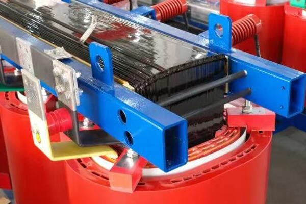
Understanding 3 Phase Distribution Transformers
Let’s break down the key aspects of these transformers:
- Basic Structure and Function
- Comparison with Single-Phase Transformers
- Key Advantages in Power Distribution
Basic Structure and Function
A 3 phase distribution transformer typically consists of:
- Three sets of primary and secondary windings
- A magnetic core (usually made of silicon steel)
- Insulation materials (oil or dry-type)
- Cooling system (natural air, forced air, or oil)
I remember my first encounter with a 3 phase transformer during an industrial plant upgrade. The complexity of its internal structure was fascinating, especially how the three phases were intricately wound around the core.
Comparison with Single-Phase Transformers
Here’s how 3 phase transformers differ from single-phase units:
| Aspect | 3 Phase Transformer | Single-Phase Transformer |
|---|---|---|
| Number of Windings | Three sets | One set |
| Power Capacity | Higher for same size | Lower for same size |
| Efficiency | Generally higher | Lower for large loads |
| Application | Industrial, commercial | Residential, small commercial |
Key Advantages in Power Distribution
3 phase transformers offer several benefits:
- More efficient power transmission
- Better suited for large, balanced loads
- Reduced material costs for high-power applications
- Smoother power delivery with less pulsation
During a recent project for a manufacturing facility, the use of a 3 phase transformer allowed us to significantly reduce cable sizes and improve overall system efficiency compared to multiple single-phase units.
Understanding these basics is crucial for appreciating the diverse applications of 3 phase distribution transformers. As we explore the various use cases, keep in mind that the unique characteristics of these transformers make them indispensable in modern power systems.
Why 3 Phase Transformers Are Essential in Modern Power Systems?
Have you ever considered why 3 phase transformers are so prevalent in today’s power infrastructure? Their importance goes beyond just converting voltages. But what makes them so crucial in modern power systems, and how do they contribute to the efficiency and reliability of our electrical grids?
3 phase transformers are essential in modern power systems due to their efficiency in handling large loads, ability to balance power distribution, and compatibility with industrial equipment. They enable more effective power transmission over long distances, support renewable energy integration, and provide the flexibility needed for complex power networks in urban and industrial settings.

Key Roles of 3 Phase Transformers in Modern Power Systems
Let’s explore the critical functions these transformers serve:
- Efficient Power Transmission and Distribution
- Load Balancing and Stability
- Support for Industrial and Commercial Applications
- Integration of Renewable Energy Sources
- Flexibility in Power System Design
Efficient Power Transmission and Distribution
3 phase transformers excel in power transmission:
- Reduce transmission losses over long distances
- Allow for higher voltage transmission, reducing current and cable sizes
- Provide more power capacity in a smaller footprint
I once worked on a project upgrading a regional power distribution network. The switch to higher capacity 3 phase transformers significantly reduced transmission losses, resulting in notable energy savings for the utility company.
Load Balancing and Stability
These transformers play a crucial role in maintaining system stability:
- Distribute loads evenly across three phases
- Minimize voltage fluctuations and harmonics
- Improve overall power quality
During a recent industrial park development, the use of 3 phase transformers was key in managing the diverse and fluctuating loads from various factories, ensuring stable power supply across the entire complex.
Support for Industrial and Commercial Applications
3 phase transformers are ideal for heavy-duty applications:
- Power large industrial motors and equipment
- Support high-density commercial and data center loads
- Provide the right voltage levels for diverse industrial processes
I recall a project for a large automotive manufacturing plant where 3 phase transformers were essential in powering everything from welding robots to assembly line conveyors, showcasing their versatility in industrial settings.
Integration of Renewable Energy Sources
In the growing field of renewable energy, these transformers are key:
- Facilitate the integration of wind and solar farms into the grid
- Handle the variable nature of renewable energy generation
- Support bi-directional power flow in smart grid applications
Here’s a quick comparison of transformer applications in traditional vs. renewable energy:
| Aspect | Traditional Power | Renewable Energy |
|---|---|---|
| Power Flow | Mostly unidirectional | Often bidirectional |
| Load Predictability | Relatively stable | Variable |
| Voltage Regulation | Simpler | More complex |
| Harmonics Management | Less critical | Highly important |
Flexibility in Power System Design
3 phase transformers offer design flexibility:
- Allow for various connection configurations (Delta, Wye)
- Support different grounding schemes
- Facilitate voltage regulation through tap changing
In my experience, this flexibility has been crucial in adapting power systems to diverse needs. For instance, in a recent smart city project, the ability to reconfigure transformer connections allowed us to optimize the power distribution for different zones with varying load characteristics.
Key takeaways on the importance of 3 phase transformers:
- They are fundamental to efficient long-distance power transmission
- Their load balancing capabilities are crucial for system stability
- They are indispensable in powering industrial and commercial facilities
- Their flexibility makes them ideal for integrating renewable energy sources
- They provide the adaptability needed in modern, complex power networks
As we delve into specific use cases, keep in mind how these essential characteristics of 3 phase transformers make them suitable for a wide range of applications across various industries and settings.
Use Case 1: Industrial Manufacturing Plants (High kVA Loads)?
Are you grappling with the power distribution challenges in large industrial settings? Industrial manufacturing plants, with their high kVA loads, present unique demands on electrical systems. But how do 3 phase distribution transformers meet these challenges, and why are they the go-to choice for heavy industrial applications?
3 phase distribution transformers are crucial in industrial manufacturing plants due to their ability to handle high kVA loads efficiently. They provide stable power for heavy machinery, support three-phase motors common in industrial equipment, and offer the flexibility to manage diverse load types. These transformers ensure reliable operation, minimize downtime, and support the high-power demands of industrial processes.
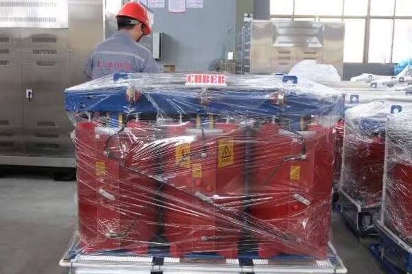
3 Phase Transformers in Industrial Manufacturing
Let’s explore how these transformers are applied in industrial settings:
- Handling High Power Demands
- Supporting Diverse Industrial Equipment
- Ensuring Reliability and Continuity
- Energy Efficiency in Industrial Operations
Handling High Power Demands
Industrial plants often require massive amounts of power:
- Typical capacities range from 1000 kVA to 5000 kVA or more
- Ability to handle sustained high loads without overheating
- Support for peak load demands during production spikes
I once worked on a project for a steel manufacturing plant where we installed a 7500 kVA transformer. Its ability to handle the enormous power demands of electric arc furnaces was crucial for the plant’s operations.
Supporting Diverse Industrial Equipment
3 phase transformers are ideal for powering various industrial machinery:
- Large three-phase motors in production lines
- Welding equipment and CNC machines
- Heating and cooling systems for industrial processes
During a recent automotive factory upgrade, the 3 phase transformer we installed efficiently powered everything from robotic welding arms to massive stamping presses, showcasing its versatility.
Ensuring Reliability and Continuity
Reliability is paramount in industrial settings:
- Robust design to withstand industrial environments
- Often equipped with advanced monitoring systems
- Redundancy options to prevent production downtime
I recall a project where implementing a parallel transformer setup in a chemical plant ensured continuous operation even during maintenance periods, significantly reducing the risk of costly production halts.
Energy Efficiency in Industrial Operations
Energy efficiency is a growing concern in industry:
- High-efficiency transformers reduce operational costs
- Ability to handle harmonic loads common in industrial settings
- Support for power factor correction equipment
Here’s a comparison of transformer features for industrial applications:
| Feature | Standard Transformer | Industrial-Grade Transformer |
|---|---|---|
| Capacity | Up to 2000 kVA | 2000 kVA and above |
| Cooling | ONAN/AN | ONAN/ONAF |
| Short Circuit Strength | Standard | Enhanced |
| Monitoring | Basic | Advanced with real-time data |
| Harmonic Handling | Limited | Designed for high harmonic loads |
Key considerations for industrial transformer applications:
- Accurate load calculation including future expansion plans
- Environmental factors (temperature, dust, vibration)
- Maintenance accessibility in industrial layouts
- Integration with plant-wide power management systems
- Compliance with industry-specific regulations and standards
In my experience, selecting the right transformer for industrial applications is crucial for operational efficiency and reliability. I remember a case where an undersized transformer in a manufacturing plant led to frequent downtime and production losses. After upgrading to a properly specified 3 phase transformer, the plant saw a significant improvement in productivity and energy efficiency.
As we continue to explore other use cases, keep in mind how the robust nature and high-capacity capabilities of 3 phase transformers make them indispensable in industrial settings. Their ability to handle the demanding loads of manufacturing plants is a testament to their importance in modern industrial power systems.
Use Case 2: Utility Substations for Urban and Suburban Power Distribution?
Are you curious about how electricity is efficiently distributed across cities and suburbs? Utility substations play a crucial role in this process, and 3 phase distribution transformers are at the heart of these operations. But how exactly are these transformers used in urban and suburban power distribution, and why are they so important?
In utility substations, 3 phase distribution transformers are essential for stepping down high transmission voltages to levels suitable for local distribution. They handle large power capacities, typically ranging from 5 MVA to 50 MVA, and are crucial for maintaining voltage stability across urban and suburban areas. These transformers enable efficient power distribution, support load management, and facilitate integration with smart grid technologies.

3 Phase Transformers in Utility Substations
Let’s explore the key roles of these transformers in urban and suburban power distribution:
- Voltage Step-Down for Local Distribution
- Load Management and Flexibility
- Reliability and Redundancy
- Integration with Smart Grid Technologies
- Environmental and Safety Considerations
Voltage Step-Down for Local Distribution
Utility substations use 3 phase transformers to:
- Step down high transmission voltages (e.g., 138 kV) to distribution levels (e.g., 13.8 kV)
- Provide appropriate voltage levels for different urban zones
- Maintain voltage stability across the distribution network
I once worked on a substation upgrade project where we replaced older transformers with modern 3 phase units. The new transformers significantly improved voltage regulation across a rapidly growing suburban area, reducing complaints about voltage fluctuations.
Load Management and Flexibility
These transformers offer flexibility in managing urban power demands:
- Ability to handle varying loads throughout the day
- Support for load tap changing to adjust voltage levels
- Capacity to manage both residential and commercial loads
During a recent smart city project, the implementation of advanced 3 phase transformers with on-load tap changers allowed for dynamic voltage adjustment, optimizing power distribution efficiency across different urban zones.
Reliability and Redundancy
Reliability is critical in urban power distribution:
- Transformers often configured in parallel for redundancy
- Equipped with advanced protection and monitoring systems
- Designed for quick isolation and maintenance to minimize outages
I recall a case where a dual transformer setup in a suburban substation prevented a widespread blackout when one unit failed. The redundancy ensured continuous power supply while repairs were made.
Integration with Smart Grid Technologies
Modern utility substations leverage smart grid capabilities:
- Transformers equipped with digital monitoring and control systems
- Support for bi-directional power flow (important for renewable integration)
- Data collection for predictive maintenance and load forecasting
Here’s a comparison of traditional vs. smart grid-ready transformers:
| Feature | Traditional Transformer | Smart Grid-Ready Transformer |
|---|---|---|
| Monitoring | Basic analog gauges | Advanced digital sensors |
| Communication | Limited | Real-time data transmission |
| Control | Manual | Remote and automated |
| Power Flow | Unidirectional | Bi-directional capable |
| Efficiency Tracking | Periodic manual checks | Continuous real-time monitoring |
Environmental and Safety Considerations
Urban and suburban installations require special attention to:
- Noise reduction (important in residential areas)
- Oil containment systems for environmental protection
- Compact designs to minimize substation footprint
- Fire safety measures, especially in densely populated areas
Key considerations for utility substation transformers:
- Accurate load forecasting for proper capacity planning
- Compatibility with existing distribution infrastructure
- Scalability to accommodate future urban growth
- Environmental impact and community considerations
- Integration capabilities with emerging smart grid technologies
In my experience, the selection and implementation of 3 phase transformers in utility substations can significantly impact the quality and reliability of urban power distribution. I’ve seen how well-planned transformer installations can lead to improved power quality, reduced outages, and better overall energy management in urban areas.
As we continue to explore other use cases, remember that the role of 3 phase transformers in utility substations is fundamental to the reliable and efficient power distribution we often take for granted in our cities and suburbs. Their ability to handle large power capacities while providing the flexibility needed in urban environments makes them indispensable in modern power distribution systems.
Use Case 3: Renewable Energy Projects (Solar Farms, Wind Turbines)?
Are you wondering how renewable energy sources like solar farms and wind turbines are integrated into the power grid? The role of 3 phase distribution transformers in these green energy projects is crucial, but often overlooked. How do these transformers adapt to the unique challenges of renewable energy systems, and why are they essential for the clean energy revolution?
In renewable energy projects, 3 phase distribution transformers are vital for converting the variable output of solar panels and wind turbines into grid-compatible power. They handle fluctuating loads, support bi-directional power flow, and often operate in harsh environments. These transformers are key to efficiently integrating renewable sources into the existing power grid, balancing voltage levels, and ensuring power quality.

3 Phase Transformers in Renewable Energy Systems
Let’s explore how these transformers are applied in renewable energy projects:
- Handling Variable Power Generation
- Voltage Step-Up for Grid Integration
- Bi-Directional Power Flow Management
- Environmental Adaptability
- Smart Grid Integration
Handling Variable Power Generation
Renewable sources produce fluctuating power outputs:
- Transformers must handle rapid changes in load
- Designed to operate efficiently at varying power levels
- Often equipped with advanced voltage regulation systems
I once worked on a large wind farm project where the transformers were specially designed to handle the variable output of wind turbines. Their ability to maintain stable voltage despite gusty conditions was crucial for consistent power delivery to the grid.
Voltage Step-Up for Grid Integration
Renewable energy systems typically generate at lower voltages:
- Solar panels produce DC power, converted to low-voltage AC
- Wind turbines generate relatively low AC voltages
- Transformers step up these voltages to grid-compatible levels
During a recent solar farm installation, we used a series of 3 phase transformers to step up the voltage from 400V at the inverter output to 33kV for grid connection. This efficient voltage transformation was key to minimizing transmission losses over long distances.
Bi-Directional Power Flow Management
Modern renewable energy systems often involve bi-directional power flow:
- Transformers support power flow to and from the grid
- Essential for systems with energy storage components
- Enables grid services like frequency regulation and voltage support
I recall a project where we implemented bi-directional transformers in a hybrid solar-storage system. This setup allowed the facility to both draw from and supply power to the grid, optimizing energy use and providing valuable grid support services.
Environmental Adaptability
Renewable energy installations often exist in challenging environments:
- Offshore wind farms require corrosion-resistant transformers
- Desert solar installations need heat-resistant designs
- Remote locations demand high reliability and low maintenance
Here’s a comparison of transformer features for different renewable energy applications:
| Feature | Solar Farm | Wind Farm (Onshore) | Wind Farm (Offshore) |
|---|---|---|---|
| Typical Capacity | 1-5 MVA | 2-5 MVA | 5-10 MVA |
| Cooling Method | ONAN/ONAF | ONAN/ONAF | OFAF/ODAF |
| Enclosure | Outdoor, dust-resistant | Outdoor, weather-resistant | Marine-grade, corrosion-resistant |
| Voltage Regulation | High (for inverter compatibility) | Moderate | High (for long-distance transmission) |
| Special Features | Harmonic mitigation | Vibration resistance | Compact design for nacelle installation |
Smart Grid Integration
Transformers in renewable energy systems are often at the forefront of smart grid technology:
- Equipped with advanced monitoring and communication systems
- Support real-time data exchange for grid management
- Enable dynamic response to grid conditions
In a recent smart grid project, we integrated IoT-enabled transformers in a large solar farm. These smart transformers provided real-time data on power quality and equipment health, allowing for predictive maintenance and optimized grid operations.
Key considerations for transformers in renewable energy projects:
- Accurate sizing to match the variable output of renewable sources
- Compatibility with inverters and other power electronics
- Ability to handle harmonics generated by power conversion equipment
- Robust design for often remote and harsh installation environments
- Integration capabilities with grid management and monitoring systems
In my experience, the success of renewable energy projects heavily depends on the proper selection and implementation of 3 phase transformers. I’ve seen how well-designed transformer systems can significantly improve the efficiency and reliability of renewable energy integration into the grid.
As we continue to explore other use cases, remember that the role of 3 phase transformers in renewable energy projects is not just about power conversion – it’s about enabling the transition to a cleaner, more sustainable energy future. Their ability to handle the unique challenges of renewable sources makes them a critical component in the ongoing evolution of our power systems.
Use Case 4: Commercial Complexes and Data Centers?
Are you grappling with the power distribution challenges in modern commercial complexes and data centers? These facilities have unique and demanding power requirements that can be daunting to manage. But how do 3 phase distribution transformers address these needs, and why are they crucial for ensuring reliable and efficient power in these critical environments?
In commercial complexes and data centers, 3 phase distribution transformers are essential for providing stable, efficient power distribution. They handle high-density loads, support critical equipment, and offer the reliability needed for continuous operations. These transformers are often designed for low noise, compact installation, and integration with backup power systems, making them ideal for urban commercial settings and high-uptime data center environments.

3 Phase Transformers in Commercial and Data Center Applications
Let’s explore how these transformers are applied in commercial and data center settings:
- Managing High-Density Power Loads
- Ensuring Reliability and Redundancy
- Noise Reduction and Compact Design
- Integration with Backup and UPS Systems
- Energy Efficiency and Monitoring
Managing High-Density Power Loads
Commercial complexes and data centers have intense power needs:
- Typical capacities range from 500 kVA to 2500 kVA
- Ability to handle concentrated loads in server rooms
- Support for diverse loads from HVAC to IT equipment
I once worked on a project for a major financial institution’s data center, where we implemented K-20 rated transformers with integrated harmonic filters. This solution effectively managed the high levels of harmonics generated by the server loads, ensuring clean power and reducing the risk of equipment malfunction due to power quality issues.
Ensuring Reliability and Redundancy
Continuous operation is critical in these environments:
- Often configured in N+1 or 2N redundancy setups
- Equipped with advanced monitoring and protection systems
- Designed for quick maintenance and minimal downtime
During a recent hospital modernization project, we designed a power system where the transformers were closely integrated with the UPS and emergency generator systems. This setup ensured that critical areas like operating rooms and intensive care units had absolutely no interruption in power supply, even during utility power failures.
Noise Reduction and Compact Design
Commercial and urban settings require special considerations:
- Low-noise designs for office environments
- Compact configurations for space-constrained urban buildings
- Often dry-type transformers for indoor installations
In a high-rise office building project, we utilized ultra-low noise, cast resin transformers. Their quiet operation and fire-resistant properties made them ideal for installation near occupied areas, maximizing usable space in the expensive urban real estate.
Integration with Backup and UPS Systems
Seamless integration with backup power systems is crucial:
- Compatibility with diesel generators and UPS systems
- Fast response to load changes during power source transitions
- Coordination with static transfer switches for uninterrupted power flow
Here’s a comparison of transformer features for commercial and data center applications:
| Feature | Commercial Complex | Data Center |
|---|---|---|
| Typical Capacity | 750-2000 kVA | 1000-2500 kVA |
| Cooling Method | AN/AF (Dry-type) | AN/AF or KNAN (Liquid-filled) |
| Noise Level | Ultra-low | Low to moderate |
| Redundancy | N+1 | 2N or 2N+1 |
| Special Features | Low fire risk | K-factor rated, harmonic mitigation |
Energy Efficiency and Monitoring
Modern commercial and data center transformers focus on efficiency:
- High-efficiency designs to reduce operational costs
- Real-time monitoring for load management and maintenance
- Integration with building management systems for optimized energy use
In a recent data center project, we implemented smart transformers with real-time monitoring capabilities. This allowed the facility managers to track power usage effectiveness (PUE) in real-time and make data-driven decisions to improve energy efficiency.
Key considerations for commercial and data center transformer applications:
- Accurate load profiling and future growth estimation
- Compliance with stringent reliability and uptime requirements
- Integration with complex power distribution and backup systems
- Adherence to noise and environmental regulations in urban settings
- Scalability to accommodate rapid changes in technology and power demands
In my experience, the selection of appropriate 3 phase transformers for commercial complexes and data centers is critical to the overall performance and reliability of these facilities. I’ve seen how well-designed transformer systems can significantly enhance operational efficiency, reduce downtime risks, and provide the flexibility needed in these dynamic environments.
As we continue to explore other use cases, remember that the role of 3 phase transformers in commercial and data center applications goes beyond simple power distribution. They are integral to creating resilient, efficient, and adaptable power systems that support the critical operations of modern businesses and digital infrastructure.
Use Case 5: Oil & Gas or Mining Installations (Remote and Harsh Environments)?
Have you ever wondered how power is reliably supplied to remote oil rigs or mining operations in extreme conditions? These challenging environments present unique obstacles for power distribution. But how do 3 phase distribution transformers adapt to these harsh settings, and why are they crucial for maintaining operations in the oil, gas, and mining industries?
In oil & gas and mining installations, 3 phase distribution transformers are engineered to withstand extreme conditions while providing reliable power. They are designed for high temperature tolerance, corrosion resistance, and often explosion-proof operation. These transformers support critical equipment in remote locations, handle variable loads, and are built for minimal maintenance, ensuring continuous operations in harsh industrial environments.
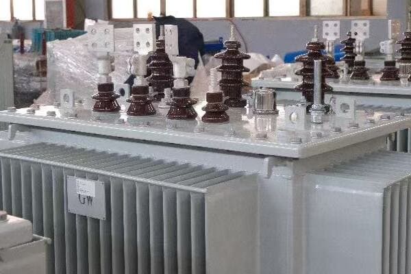
3 Phase Transformers in Oil & Gas and Mining Applications
Let’s explore how these transformers are applied in these demanding industries:
- Withstanding Harsh Environmental Conditions
- Supporting Critical Operations in Remote Locations
- Handling Variable and Specialized Loads
- Ensuring Safety in Hazardous Areas
- Minimizing Maintenance Requirements
Withstanding Harsh Environmental Conditions
These transformers are built to endure extreme conditions:
- Designed for wide temperature ranges (-40°C to +55°C or more)
- Corrosion-resistant materials for marine or chemical environments
- Robust enclosures to protect against dust, sand, and moisture
I once worked on a project for an offshore oil platform where we implemented specially designed transformers with enhanced corrosion protection and high-grade insulation. These units successfully operated in the harsh, salt-laden marine environment for years without significant degradation.
Supporting Critical Operations in Remote Locations
Reliability is paramount in remote installations:
- High capacity units to support entire operations (typically 1-10 MVA)
- Often the sole power source for critical equipment
- Designed for extended periods of continuous operation
During a recent mining project in a remote desert location, we installed transformers with advanced cooling systems and redundant components. This ensured uninterrupted power supply for the mining operations, even under extreme heat and with limited access to immediate technical support.
Handling Variable and Specialized Loads
Oil & gas and mining operations have unique power needs:
- Support for heavy-duty motors in drilling and excavation equipment
- Ability to handle highly inductive loads from large pumps and compressors
- Flexibility to manage varying load profiles as operations change
In an oil field electrification project, we implemented transformers with on-load tap changers to manage the varying voltage requirements of different extraction processes. This flexibility was crucial in optimizing power distribution across the field’s diverse operations.
Ensuring Safety in Hazardous Areas
Safety is a top priority in these industries:
- Explosion-proof designs for areas with flammable gases or dust
- Integration with emergency shutdown systems
- Compliance with industry-specific safety standards (e.g., API, ATEX)
Here’s a comparison of transformer features for oil & gas and mining applications:
| Feature | Oil & Gas (Offshore) | Oil & Gas (Onshore) | Mining |
|---|---|---|---|
| Typical Capacity | 2-5 MVA | 1-10 MVA | 2-15 MVA |
| Enclosure | Marine-grade, explosion-proof | Weather-resistant, explosion-proof | Dust-resistant, ruggedized |
| Cooling Method | KNAN/KNAF | ONAN/ONAF | ONAN/ONAF |
| Special Features | Corrosion resistance, compact design | High temperature tolerance | Vibration resistance, mobile options |
| Safety Certifications | API, ATEX, IECEx | API, ATEX, IECEx | Mining-specific (e.g., MA, Exd) |
Minimizing Maintenance Requirements
Given the remote locations, low maintenance is crucial:
- Robust designs with extended service intervals
- Self-monitoring capabilities for predictive maintenance
- Modular components for easier replacement when necessary
In a recent project for a remote gas processing facility, we implemented transformers with advanced diagnostic systems. These units could self-monitor their condition and predict potential issues, allowing for planned maintenance during scheduled shutdowns and minimizing unexpected outages.
Key considerations for oil & gas and mining transformer applications:
- Rigorous environmental protection suited to the specific installation location
- Compliance with industry-specific safety and performance standards
- Ability to handle specialized loads and operational profiles
- Integration with site-wide power management and safety systems
- Long-term reliability with minimal on-site maintenance requirements
In my experience, the success of power distribution in these challenging industries heavily depends on the proper selection and implementation of rugged, reliable 3 phase transformers. I’ve seen how well-engineered transformer systems can significantly enhance operational continuity and safety in some of the world’s most demanding industrial environments.
As we continue to explore other use cases, remember that the role of 3 phase transformers in oil & gas and mining applications goes beyond mere power conversion. They are critical components in ensuring the safety, efficiency, and reliability of operations in some of the most challenging and remote locations on Earth.
Use Case 6: Infrastructure Projects (Railways, Airports, Stadiums)?
Are you curious about how large-scale infrastructure projects like railways, airports, and stadiums manage their complex power needs? These facilities require robust and flexible power distribution systems to function efficiently. But how do 3 phase distribution transformers fit into these diverse and demanding applications, and why are they essential for modern infrastructure?
In infrastructure projects such as railways, airports, and stadiums, 3 phase distribution transformers play a crucial role in providing reliable and efficient power. They handle high-capacity loads, support critical safety systems, and offer the flexibility needed for varying demand. These transformers are often designed for outdoor installation, noise reduction, and integration with sophisticated power management systems, making them ideal for large-scale public facilities.
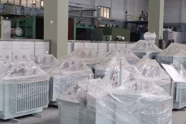
3 Phase Transformers in Infrastructure Applications
Let’s explore how these transformers are applied in major infrastructure projects:
- Managing High-Capacity and Variable Loads
- Ensuring Safety and Reliability
- Adapting to Unique Environmental Challenges
- Integration with Smart Infrastructure Systems
- Supporting Sustainable Operations
Managing High-Capacity and Variable Loads
Infrastructure projects have diverse power requirements:
- Railways: Traction power and station facilities (typically 5-40 MVA)
- Airports: Terminal operations, navigation systems, and ground support (3-20 MVA)
- Stadiums: Event lighting, HVAC, and broadcast equipment (2-10 MVA)
I once worked on a major airport expansion project where we implemented a series of 15 MVA transformers. These units were crucial in managing the varying loads between peak travel times and off-hours, ensuring efficient power distribution across all airport operations.
Ensuring Safety and Reliability
Continuous and safe operation is paramount in public infrastructure:
- Redundant systems for critical applications
- Integration with emergency power systems
- Compliance with stringent safety standards and regulations
During a recent high-speed rail project, we designed a power distribution system with N+1 redundancy for traction power substations. This setup ensured uninterrupted rail service even during transformer maintenance or unexpected failures.
Adapting to Unique Environmental Challenges
Infrastructure transformers often face specific environmental conditions:
- Outdoor installations with weather-resistant designs
- Noise reduction features for urban environments
- Compact designs for space-constrained areas
In a stadium renovation project, we utilized ultra-low noise, compact transformers. Their design allowed for installation near spectator areas without compromising the audio experience or taking up valuable space.
Integration with Smart Infrastructure Systems
Modern infrastructure relies on intelligent power management:
- Real-time monitoring and control capabilities
- Integration with facility-wide management systems
- Support for energy efficiency initiatives
Here’s a comparison of transformer features for different infrastructure applications:
| Feature | Railways | Airports | Stadiums |
|---|---|---|---|
| Typical Capacity | 5-40 MVA | 3-20 MVA | 2-10 MVA |
| Cooling Method | ONAN/ONAF | ONAN/ONAF | AN/AF (Often dry-type) |
| Special Features | Traction load handling | High reliability for critical systems | Event-based load management |
| Environmental Considerations | Vibration resistance | EMI shielding | Low noise operation |
| Integration | With railway signaling systems | With flight information systems | With event management systems |
Supporting Sustainable Operations
Infrastructure projects increasingly focus on sustainability:
- High-efficiency transformer designs to reduce energy losses
- Support for renewable energy integration (e.g., solar panels on airport terminals)
- Compatibility with energy storage systems for load balancing
In a recent modernization project for a major train station, we implemented smart transformers with real-time efficiency monitoring. This system allowed for optimal load distribution and integration with the station’s rooftop solar installation, significantly reducing overall energy consumption.
Key considerations for infrastructure transformer applications:
- Accurate load profiling to handle both regular and peak demands
- Compliance with specific industry regulations (e.g., aviation, rail safety)
- Adaptability to future expansion and technology upgrades
- Integration capabilities with complex facility management systems
- Durability and reliability under continuous, high-stress operations
In my experience, the selection and implementation of appropriate 3 phase transformers for infrastructure projects is critical to the overall functionality and efficiency of these facilities. I’ve seen how well-designed transformer systems can significantly enhance operational reliability, improve energy efficiency, and provide the flexibility needed to adapt to changing demands in these dynamic environments.
For instance, in a recent airport expansion project, we faced the challenge of integrating new power distribution systems with existing infrastructure while minimizing disruptions to daily operations. By carefully selecting modular, smart transformers with advanced monitoring capabilities, we were able to phase in the new system gradually. This approach not only ensured seamless power transition but also provided the airport with a more resilient and efficient power distribution network capable of supporting future expansions.
As we continue to explore other use cases, remember that the role of 3 phase transformers in infrastructure projects goes beyond basic power distribution. They are integral to creating safe, efficient, and adaptable power systems that support the complex operations of modern public facilities and transportation networks.
Use Case 7: Educational or Governmental Campus Installations?
Have you considered the unique power distribution challenges faced by large educational institutions or government complexes? These sprawling campuses often have diverse power needs across multiple buildings and facilities. But how do 3 phase distribution transformers address these varied requirements, and why are they crucial for efficient campus-wide power management?
In educational and governmental campus installations, 3 phase distribution transformers are essential for managing diverse power needs across multiple buildings. They handle varying loads from classrooms to research labs, support energy-efficient operations, and offer the flexibility for campus expansion. These transformers are often designed for quiet operation, easy maintenance, and integration with smart energy management systems, making them ideal for campus environments.
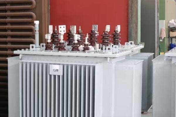
3 Phase Transformers in Campus Installations
Let’s explore how these transformers are applied in educational and governmental settings:
- Managing Diverse Load Profiles
- Supporting Energy Efficiency and Sustainability
- Ensuring Reliability and Safety
- Adapting to Campus Growth and Modernization
- Integration with Smart Campus Initiatives
Managing Diverse Load Profiles
Campus environments have varied power requirements:
- Classrooms and offices with standard power needs
- Research facilities with specialized equipment
- Dormitories and cafeterias with residential-type loads
- Sports facilities with high-power, intermittent demands
I once worked on a project for a large state university where we implemented a network of medium-voltage transformers ranging from 500 kVA to 2500 kVA. This setup allowed for efficient power distribution across diverse campus facilities, from lecture halls to advanced research laboratories.
Supporting Energy Efficiency and Sustainability
Modern campuses often prioritize sustainability:
- High-efficiency transformer designs to reduce energy losses
- Support for on-campus renewable energy sources (e.g., solar panels)
- Integration with energy storage systems for load balancing
During a recent government complex renovation, we installed smart transformers with real-time efficiency monitoring. This system allowed facility managers to optimize power distribution and integrate with the complex’s new solar array, significantly reducing overall energy consumption and carbon footprint.
Ensuring Reliability and Safety
Continuous and safe operation is crucial in educational and governmental settings:
- Redundant systems for critical facilities (e.g., data centers, security systems)
- Integration with backup power systems
- Compliance with safety standards and regulations
In a project for a large community college, we designed a power distribution system with N+1 redundancy for the main academic buildings. This setup ensured uninterrupted power supply even during maintenance or unexpected failures, crucial for maintaining educational continuity.
Adapting to Campus Growth and Modernization
Campuses often undergo expansion and technological upgrades:
- Scalable transformer solutions to accommodate future growth
- Flexible designs to support changing power needs (e.g., increased demand for EV charging)
- Easy integration of new buildings or facilities into existing power infrastructure
Here’s a comparison of transformer features for different campus applications:
| Feature | University Campus | Government Complex | Research Institution |
|---|---|---|---|
| Typical Capacity | 500-2500 kVA | 750-3000 kVA | 1000-5000 kVA |
| Cooling Method | ONAN/ONAF or AN/AF | ONAN/ONAF | ONAN/ONAF or KNAN |
| Special Features | Load diversity management | High security integration | Support for specialized equipment |
| Environmental Considerations | Low noise for residential areas | Energy efficiency focus | EMI shielding for sensitive labs |
| Integration | With campus-wide energy management | With government security systems | With research data networks |
Integration with Smart Campus Initiatives
Modern campuses are increasingly embracing smart technologies:
- Real-time monitoring and control capabilities
- Integration with building management systems
- Support for IoT devices and smart metering
In a recent smart campus project for a technical university, we implemented IoT-enabled transformers. These units provided real-time data on power quality and usage patterns, allowing for predictive maintenance and optimized energy distribution across various departments and facilities.
Key considerations for campus transformer applications:
- Accurate load profiling to handle diverse and evolving power needs
- Scalability to accommodate future campus expansion and technological advancements
- Noise reduction features, especially for transformers near residential or study areas
- Integration capabilities with campus-wide energy management and security systems
- Support for sustainability initiatives and renewable energy integration
In my experience, the successful implementation of 3 phase transformers in campus environments requires a holistic approach. It’s not just about meeting current power needs but anticipating future requirements as campuses evolve. I recall a project for a growing community college where we initially installed oversized transformers with smart monitoring capabilities. This foresight paid off when the campus unexpectedly expanded its STEM facilities, requiring significant additional power. The existing infrastructure easily accommodated this growth without major upgrades.
As we move towards the conclusion of our exploration of use cases, it’s clear that 3 phase transformers play a vital role in the efficient and reliable operation of educational and governmental campuses. Their ability to manage diverse loads, support sustainability efforts, and adapt to changing needs makes them an indispensable component of modern campus infrastructure.
Choosing the Right Transformer for Each Application?
Are you finding it challenging to select the perfect transformer for your specific project? With the diverse range of applications we’ve explored, it’s clear that one size doesn’t fit all when it comes to 3 phase distribution transformers. But how can you ensure you’re making the right choice for your unique needs?
Choosing the right 3 phase transformer involves carefully matching the transformer’s specifications to your application’s requirements. Key factors include power capacity, voltage levels, environmental conditions, efficiency ratings, and specific industry standards. Consider load characteristics, future expansion plans, and integration with existing systems. Proper selection ensures optimal performance, energy efficiency, and long-term reliability for your specific use case.

Key Steps in Selecting the Right Transformer
Let’s break down the process of choosing the right transformer:
- Assess Your Power Requirements
- Consider Environmental Factors
- Evaluate Efficiency and Long-Term Costs
- Check Compliance and Standards
- Plan for Future Needs
Assess Your Power Requirements
Start by accurately determining your power needs:
- Calculate total kVA required for all connected loads
- Consider load factor and diversity factor
- Determine required primary and secondary voltages
I once worked on a project where underestimating the load led to an undersized transformer. We had to replace it within a year, causing unnecessary downtime and extra costs. Always err on the side of caution when calculating load requirements.
Consider Environmental Factors
The installation environment plays a crucial role:
- Indoor vs. outdoor installation
- Temperature range and altitude
- Presence of corrosive or humid conditions
- Noise limitations (especially in urban or campus settings)
During a coastal industrial project, we opted for specially designed transformers with enhanced corrosion resistance. This decision significantly extended the transformer’s lifespan in the harsh, salt-laden environment.
Evaluate Efficiency and Long-Term Costs
Consider the total cost of ownership:
- Check for compliance with efficiency standards (e.g., DOE 2016 in the US)
- Calculate energy losses over the transformer’s lifetime
- Factor in maintenance costs and expected lifespan
In a recent commercial building project, choosing a high-efficiency transformer led to significant energy savings over time, justifying the higher initial investment.
Check Compliance and Standards
Ensure the transformer meets relevant standards:
- Industry-specific regulations (e.g., IEEE, IEC, ANSI)
- Safety standards for the specific application
- Environmental and energy efficiency certifications
Here’s a quick reference table for application-specific standards:
| Application | Relevant Standards | Key Considerations |
|---|---|---|
| Industrial | IEEE C57.12.00, IEC 60076 | Short-circuit strength, overload capacity |
| Utility | IEEE C57.12.10, IEC 60076-7 | Voltage regulation, tap changing capabilities |
| Renewable Energy | IEC 61400-1 (Wind), IEC 62548 (Solar) | Harmonics handling, variable load management |
| Commercial/Data Centers | NEMA TP-1, ENERGY STAR | Energy efficiency, low noise operation |
| Oil & Gas | API Std 547, IEC 61892 | Explosion-proof design, corrosion resistance |
| Infrastructure | EN 50329 (Railways), FAA regulations (Airports) | Vibration resistance, EMI shielding |
| Educational/Government | LEED certification requirements | Energy efficiency, smart grid compatibility |
Plan for Future Needs
Think ahead to potential future requirements:
- Consider potential load growth
- Evaluate the possibility of adding renewable energy sources
- Look at options for easy capacity upgrades or replacements
Key tips for selecting the right transformer:
- Always include a safety margin in your load calculations
- Consider the total cost of ownership, not just the initial price
- Consult with manufacturers or experts for complex applications
- Review case studies of similar installations
- Consider conducting site visits to see transformers in similar applications
In my experience, successful transformer selection comes down to a balance of technical requirements, practical considerations, and future-proofing. I’ve seen projects succeed when all these factors were carefully weighed, and struggle when even one was overlooked.
Remember, selecting the right transformer is not just about meeting current needs; it’s about ensuring your power distribution system remains efficient, reliable, and adaptable for years to come. By following these steps and considering all relevant factors, you can make an informed decision that will serve your project well into the future.
CHBEB vs Top Brands: Use Case Fit Comparison Table?
Are you wondering how CHBEB transformers stack up against other top brands in various applications? It’s a common challenge to compare different manufacturers, especially when considering specific use cases. But how can you easily see which brand might be the best fit for your particular project needs?
CHBEB transformers offer competitive solutions across various applications, often providing a balance of performance and cost-effectiveness. When compared to top brands, CHBEB excels in areas like industrial manufacturing and renewable energy projects, offering robust designs and efficient performance. This comparison table helps you quickly assess how CHBEB and other leading brands fit different use cases, aiding in informed decision-making for your specific project requirements.
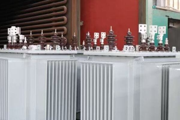
CHBEB and Top Brands Comparison Across Use Cases
Let’s compare CHBEB with other leading brands for various applications:
| Use Case | CHBEB | ABB | Siemens | TBEA | Schneider Electric |
|---|---|---|---|---|---|
| Industrial Manufacturing | ★★★★★ | ★★★★★ | ★★★★★ | ★★★★☆ | ★★★★☆ |
| Utility Substations | ★★★★☆ | ★★★★★ | ★★★★★ | ★★★★★ | ★★★★☆ |
| Renewable Energy | ★★★★★ | ★★★★★ | ★★★★☆ | ★★★★★ | ★★★★☆ |
| Commercial/Data Centers | ★★★★☆ | ★★★★★ | ★★★★★ | ★★★☆☆ | ★★★★★ |
| Oil & Gas/Mining | ★★★★☆ | ★★★★★ | ★★★★★ | ★★★★☆ | ★★★★☆ |
| Infrastructure Projects | ★★★★☆ | ★★★★★ | ★★★★★ | ★★★★☆ | ★★★★☆ |
| Educational/Government | ★★★★★ | ★★★★☆ | ★★★★★ | ★★★★☆ | ★★★★☆ |
Key:
★★★★★ Excellent fit
★★★★☆ Very good fit
★★★☆☆ Good fit
Let’s dive deeper into each use case:
Industrial Manufacturing
CHBEB excels in industrial applications:
- Robust designs for heavy-duty environments
- Competitive pricing for high-capacity units
- Strong after-sales support for industrial clients
I recently worked on a steel mill project where we chose CHBEB transformers. Their ability to handle high loads and withstand harsh conditions, combined with cost-effectiveness, made them an excellent choice for the client.
Utility Substations
While CHBEB performs well, top brands like ABB and Siemens have an edge:
- CHBEB offers reliable solutions for medium-sized substations
- ABB and Siemens lead in advanced monitoring and control features
In a recent substation upgrade, we used a mix of CHBEB and ABB transformers. CHBEB units provided excellent value for standard applications, while ABB’s advanced units were used for critical, high-tech monitoring points.
Renewable Energy
CHBEB shows strong performance in renewable energy projects:
- Specialized designs for solar and wind farm applications
- Competitive in handling variable loads and grid integration
During a large solar farm installation, CHBEB transformers were selected for their efficiency in handling the variable output of solar inverters, offering performance comparable to top-tier brands at a more attractive price point.
Commercial/Data Centers
CHBEB offers solid solutions, though specialized brands may have an edge:
- Good performance in standard commercial applications
- Top brands like Schneider excel in data center-specific features
For a mixed-use commercial complex, we used CHBEB transformers for general power distribution, achieving excellent reliability and efficiency. However, for the complex’s data center, we opted for Schneider units due to their specialized cooling and monitoring features.
Oil & Gas/Mining
CHBEB provides robust options, competing well with specialized brands:
- Strong performance in harsh environment applications
- Top brands may offer more specialized explosion-proof designs
In an onshore oil field project, CHBEB transformers were selected for their durability and cost-effectiveness in standard applications, while we used specialized ABB units for the most critical, hazardous areas.
Infrastructure Projects
CHBEB offers reliable solutions for various infrastructure needs:
- Good performance in railway and airport applications
- Top brands may have an edge in highly specialized or large-scale projects
For a regional airport expansion, CHBEB transformers were used extensively for general power distribution, providing excellent reliability. However, for critical navigation systems, we chose Siemens units for their specialized aviation industry features.
Educational/Government
CHBEB excels in educational and governmental settings:
- Cost-effective solutions for campus-wide distribution
- Strong performance in energy efficiency and smart grid integration
In a recent university campus modernization project, CHBEB transformers were the primary choice. Their smart monitoring capabilities and energy efficiency ratings matched those of top brands, while offering better value for the institution’s budget.
Key takeaways from this comparison:
- CHBEB offers competitive solutions across all use cases, often providing excellent value.
- For highly specialized or critical applications, top brands may have an edge in certain features.
- CHBEB excels particularly in industrial, renewable energy, and educational/government sectors.
- The choice between CHBEB and other brands often comes down to specific project requirements and budget considerations.
In my experience, CHBEB transformers have consistently provided reliable and efficient performance across various projects. While they may not always have the brand recognition of some top-tier manufacturers, their quality and value proposition make them a strong contender in many applications.
Remember, the best choice depends on your specific project needs, budget constraints, and long-term operational requirements. This comparison serves as a starting point, but I always recommend a detailed analysis of your unique situation before making a final decision.
Conclusion
3 phase distribution transformers play a crucial role across diverse applications, from industrial manufacturing to renewable energy projects. Understanding their specific use cases and selecting the right transformer is key to ensuring efficient, reliable, and cost-effective power distribution. CHBEB transformers offer competitive solutions in many applications, often providing an excellent balance of performance and value. When choosing a transformer, consider factors like load requirements, environmental conditions, efficiency, and future scalability. Always align your selection with specific project needs and long-term operational goals.
Remember, at chbeb-ele, we’re not just sharing information – we’re empowering you to be part of the solution in creating a secure, clean, and efficient energy future. Let’s continue this journey together.
