Introduction
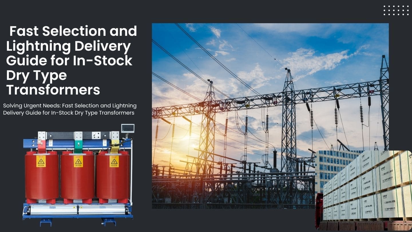
When a transformer breaks down without warning, every hour of downtime costs money, puts strain on customers, and requires urgent calls to suppliers. In-stock dry-type transformers are a solid way to get what you need right now. They’re pre-tested, ready to ship, and certified for use right away, so you don’t have to wait weeks for a custom build.
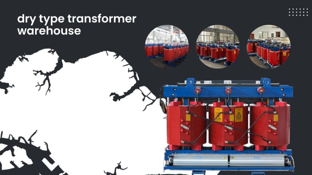
Rapid Selection: How to Find Your Model in Our Live Inventory
When time is running out, consumers need speed, not a lot of quotes. With a live inventory system, engineers can quickly check stock levels, compare ratings, and confirm delivery windows. While your transformer is on its way, you can arrange the installation.
The In-Stock Advantage: Why Choose Stock Over Custom for Urgent Projects
Every project manager has faced this problem: the transformer on site fails, and a replacement must arrive within days. Choosing a stock unit eliminates design time, approvals, and material lead delays.
Some of the main benefits of having transformers in stock are:
- No waiting for production: Each unit is already put together and tested.
- Cost is easy to predict: the price is set and there are no fees for changing the design.
- Verified performance: The units have passed factory tests that are done regularly.
- Shorter logistics chain: shipping directly from the regional warehouse.
In-stock dry-type transformers give you peace of mind when you need it most, whether you need to quickly replace a transformer, improve a substation, or set up a temporary power supply.
Live Inventory Catalog: A Quick Look at Common Capacities and Important Specs
Here is a list of the most common in-stock capacities and configurations that are usually available:
| Capacity (kVA) | High Voltage | Low Voltage | Cooling | Insulation Class | Typical Applications |
|---|---|---|---|---|---|
| 50–315 | 10 / 0.4 kV | 0.4 kV | AN | F | Commercial buildings, schools |
| 400–800 | 10 / 0.4 kV | 0.4 kV | AN | F | Factories, workshops |
| 1000–1600 | 10 / 0.4 kV | 0.4 kV | AF | H | Data centers, hospitals |
| 2000–3150 | 35 / 10 kV | 10 / 0.4 kV | AF | H | Public utilities, substations |
All of the units on the list have been tested in the factory according to IEC 600761 standards. This makes sure that they have minimal loss, stable insulation, and can safely work with both steady and changing loads.
The 3-Step Quick Selection Method: A Way to Match Needs Right Away Without Making Mistakes
Step 1: Check the voltage and capacity
Add up all the loads and then add 25% for safety and growth. Make sure the voltage levels match the network (usually 10/0.4 or 35/10 kV).
Step 2: Choose the type of installation and cooling
Pick AN (air natural) for normal indoor use or AF (air forced) for places with a lot of weight or not enough room.
Step 3: Check the environmental needs
Check the insulation class, IP protection, and noise level against the conditions on the location. Check the humidity and ventilation before making your final decision.
Once these conditions are met, you can reserve, test, and ship your transformer in as little as 24 hours.
Service Commitment: Nationwide Lightning Delivery and Zero-Risk Quality
Quick delivery is only important if the quality is certain. Transformers that are in stock are not leftover stock; they are certified items that meet the same criteria as units that are produced to order.
Logistics Timeline: Delivery all around the country and promised lead times (broken down by region)
Quick responses are achievable thanks to good logistics. Regional warehouses and coordinated transportation networks make sure that the whole country is covered without any problems.
| Region | Dispatch Time | Average Transit | Total Delivery |
|---|---|---|---|
| Eastern & Southern China | Within 24h | 1–2 days | 2–3 days |
| Central & Northern China | Within 24h | 2–3 days | 3–4 days |
| Western & Northeast China | Within 48h | 3–4 days | 4–6 days |
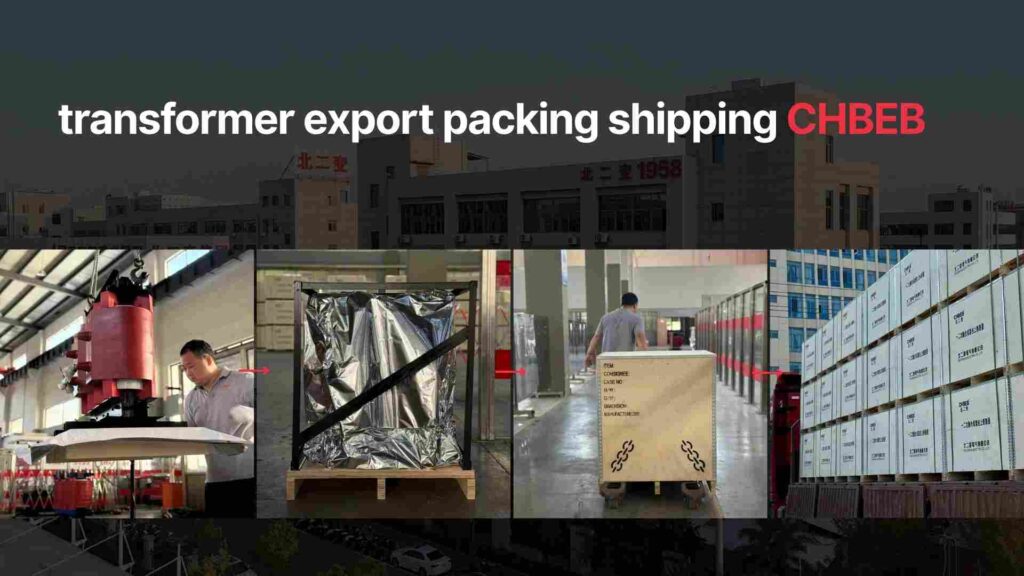
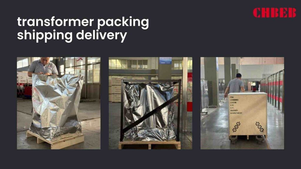
Each product is safely packed with pallets that don’t shake, corners that don’t break, and sealed wrapping2. Long-distance transportation uses temperature-controlled trucks to keep the insulation intact.
With real-time shipment tracking, project managers can keep an eye on every step of the process, from leaving the warehouse to arriving at the site, so installation crews can get ready right away.
Quality Guarantee: All In-Stock Units Have International Standard Certification
Just because something is urgent doesn’t mean it’s not checked. Before being put in stock, all dry-type transformers that are in stock go through comprehensive standard testing. There is a full test report with every machine, and the serial number makes it easy to find.
Tests that are common include:
- Checking the winding resistance and vector group
- Measurement of load and no-load loss
- Tests for withstanding induced and applied voltage
- Tests for partial discharge and insulating resistance
Under IEC 60076, ISO 9001, and ISO 14001 systems, all units are made and tested. Each one comes with a one-year warranty from the factory and lifelong technical assistance for maintenance or changing settings.
⚙️ CHBEB — Reliable Partner for In-Stock Dry-Type Distribution Transformers
With over 60 years of transformer manufacturing expertise, CHBEB has become one of China’s most trusted suppliers of dry-type and distribution transformers.
The company operates two factories in Wenzhou, one in Nanjing, and a technical and logistics office in Beijing, ensuring both strong production capacity and fast nationwide delivery.
Why Buyers Trust CHBEB
- Proven Reliability: A qualified supplier for the State Grid Corporation of China, with a spotless record of zero major accidents.
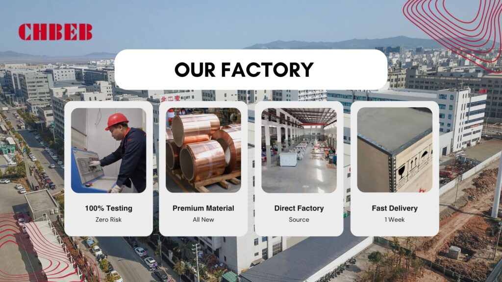
- Strict Quality Commitment: Every transformer is made from 100% new copper, premium-grade silicon steel, and Class F/H insulation, guaranteeing long-term performance and low loss.
- Comprehensive Testing: Each in-stock transformer is fully tested before release, covering no-load and load loss, insulation resistance, and partial discharge per IEC 60076.
- Fast-Track Delivery: Standard models are ready to dispatch within 24 hours, ensuring critical projects stay on schedule.
- Custom Stock Planning: Flexible inventory management aligns with clients’ procurement cycles and regional demand.
- Global Reach: Exported to Russia, Southeast Asia, Africa, and Belt and Road countries, CHBEB transformers meet ISO 9001, ISO 14001, and CE/CB international standards.
Whether it’s a time-sensitive replacement or a high-reliability dry-type transformer for long-term operation, CHBEB delivers what modern projects need most — speed, precision, and confidence backed by decades of engineering experience.
👉 Looking for a distribution transformer manufacturer that combines Chinese manufacturing strength with international standards?Contact CHBEB for a tailored solution or Download our full transformer catalog here.
Frequently Asked Questions (FAQ)
1. How soon can a dry-type transformer be delivered?
Standard CHBEB models can be dispatched within 24 hours. Delivery to Eastern or Southern China takes 2–3 days; nationwide coverage completes within six days. Custom models typically require 15–25 days for production and testing.
2. What kVA capacities are available in stock?
Typical inventory covers 50 to 3150 kVA units with 10/0.4 kV and 35/10 kV ratings. Contact our engineers for real-time stock confirmation.
3. What’s the difference between in-stock and custom transformers?
In-stock transformers are standard models that have passed all factory tests and are ready to ship. Custom transformers are tailored to special parameters such as altitude, connection group, or cooling type. Both follow IEC 60076 and ISO 9001 quality procedures.
4. Are in-stock transformers reliable?
Absolutely. Each unit is brand-new and certified—not excess inventory. Every transformer undergoes full routine and type testing, with a test report and traceable serial number.
5. How can I quickly confirm the voltage level I need?
Simply provide your equipment list or input/output voltage requirements. Our engineers can calculate capacity and voltage rating within 30 minutes to match your grid standard.
6. Can a dry-type transformer be shipped the same day?
Yes. Orders confirmed before 12 p.m. can be tested, packed, and shipped the same day. Urgent projects can be scheduled for overnight loading and express dispatch.
7. What does “nationwide lightning delivery” mean?
CHBEB guarantees the following lead times:
West & Northeast China: 4–6 days
Every shipment includes real-time tracking and arrival notification.
East & South China: 48 hours delivery
Central & North China: 3–4 days
Conclusion
In-stock dry-type transformers are no longer just a stopgap for urgent projects— they offer a practical path to reliability, compliance, and speed in modern power distribution.
Each fully tested and IEC-certified unit gives engineers the confidence to act quickly without compromising safety or quality. Combined with real-time logistics and technical support, in-stock solutions help ensure power continuity across industries.
As 2025 projects demand faster delivery and proven performance, experienced manufacturers like CHBEB demonstrate how readiness, testing discipline, and long-term reliability can coexist—turning emergency supply into engineered assurance.
Introduction
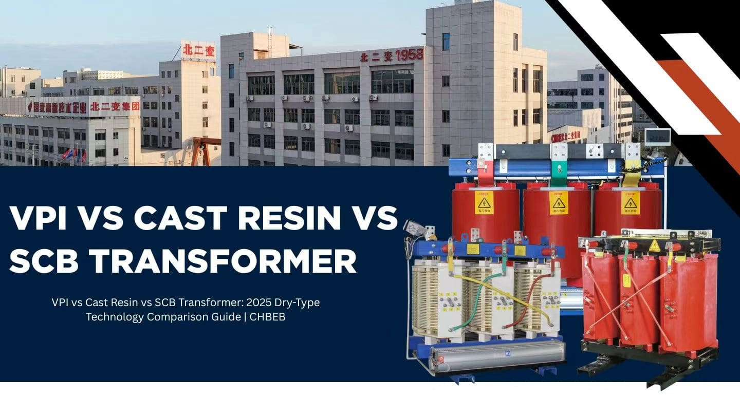
It shouldn’t feel like a gamble to pick the correct transformer. But one small detail—the type of insulation—can cause projects to lose money or put people at risk. If you’re building an industrial plant or a public building, knowing the distinctions between VPI, Cast Resin, and SCB dry-type transformers will help you make a decision that you can be sure is safe.
Understanding the Basics: What “Dry-Type Transformer” Really Means
Transformers don’t always need oil to work. “Dry-type” just indicates that the windings are insulated and cooled by air or solid materials instead of oil. These units are safer to use inside, better for the environment, and need less upkeep.
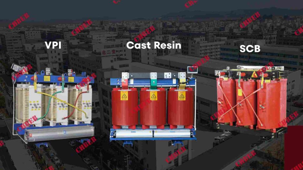
Some of the most common dry-type technologies are:
VPI (Vacuum Pressure Impregnation)
Cast Resin (Epoxy Encapsulated)
SCB Series: Standard Dry-Type Distribution Transformers
They all do the same electrical job: move power. However, they differ in the materials they are made of, how they are made, and how well they work over time.
Cost & Procurement: How Each Technology Affects Your Budget and Timeline
When time is short, price and lead time are important. But a cheap bid up front doesn’t always guarantee the lowest long-term expense.
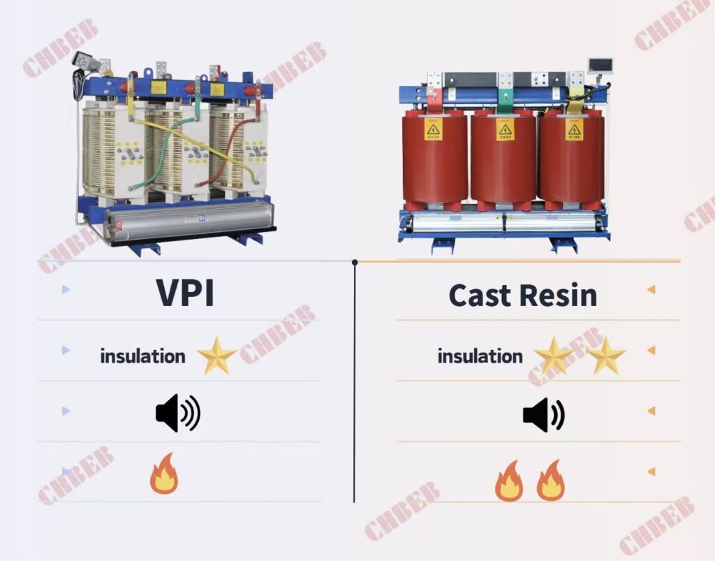
VPI: Quick and Cheap
VPI transformers1 are manufactured by putting varnish on the windings while they are under vacuum and pressure. This makes a strong coating.
Pros: Cheap, quick shipping, and easy to fix.
Cons: It doesn’t resist fire and water very well.
💰 Usually 10–25% less expensive than cast resin kinds, making them great for tasks that need to balance speed and cost.
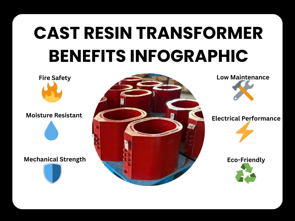
Cast Resin: Strong and Fire-Safe
When epoxy resin is put into molds and hardens around the windings, it makes a completely sealed system.
Pros: Very safe from fire, doesn’t attract moisture, and puts itself out.
Cons: More expensive, takes longer to make, and is harder to fix.
🔥 Best for hospitals, tunnels, and metro systems where uptime and fire risk are very important.
The Balanced Option in the SCB Series
The SCB family includes both VPI and cast resin technologies:
- SCB10/11 → VPI-based for flexibility and low cost
- SCB12: Made of cast resin for more safety and dependability
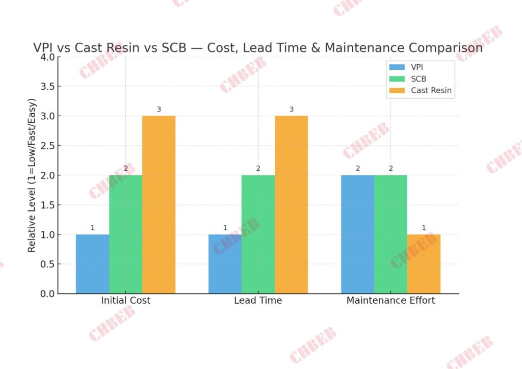
| Feature | VPI Transformer | Cast Resin Transformer | SCB Series |
|---|---|---|---|
| Insulation Medium | Varnish impregnation | Solid epoxy resin | Both types |
| Fire Resistance | Good | Excellent | Depends on model |
| Moisture Resistance | Medium | Excellent | Varies |
| Maintenance | Simple | Minimal | Moderate |
| Cost | Lower | Higher | Mid-range |
Risk and Reliability: What Happens After Commissioning
You can see the cost, but you can’t see the risk. After it is turned on, the reliability of your transformer depends on the weather and how well it works in a fire.
Fire and Safety Performance
Choose Cast Resin if your site has severe fire restrictions.
It has epoxy insulation that puts itself out and doesn’t make much smoke when it breaks down.
VPI systems can catch fire, but they won’t burn up at high temperatures. They are good for factories and regular commercial buildings.
Resistant to Moisture and the Environment
VPI transformers work best in clean, indoor areas.
High humidity can steadily damage varnish insulation, though, especially in coastal, tropical, or underground areas.
Cast resin units are completely sealed, making them great for hard or corrosive settings since they keep out dust and moisture.
Time for Maintenance and Downtime
- VPI: Easier to keep up with or re-impregnate during an overhaul.
- Cast resin: Doesn’t need much care, but it’s hard to fix if it gets broken.
Cast resin makes your site more stable for longer and causes fewer service interruptions if you can’t get to it easily.
Life-Cycle Economics: Beyond Initial CAPEX
The cost up front is simply one element of the situation. Over the course of 20 years, differences in efficiency, loss level, and downtime might affect the picture of the real cost.
| Factor | VPI | Cast Resin |
|---|---|---|
| Initial Cost | Lower | Higher |
| Fire & Moisture Risk | Medium | Very Low |
| Maintainability | Easy | Limited |
| Expected Lifespan | 20–25 years | 25–30 years |
| Best Application | Industrial / Commercial | Public or Mission-Critical Sites |
💡 TCO Insight:
Think about how much energy is lost (when the machine is not running and when it is), how often it needs maintenance, and how long it takes to replace it.
Sometimes spending more money on capital expenses today can save you money over the long term and cause fewer problems.
Choosing Smart: Match Type to Your Project
There is no one “best” transformer for everyone; there is just the one that works best for your needs and budget.
When to Choose VPI
- You need transformers that are cheap or can be delivered quickly.
- The place is dry, clean, and easy to get to.
- There is a moderate risk of fire, and maintenance access is possible.
When to Use Cast Resin
- Safety from fire or water is a must.
- The area is near the seaside, humid, or partly outside.
- The expenses of downtime are higher than the savings up front.
When to Choose SCB Series
- You want a dry-type solution that is standardized and meets IEC standards.
- The facility has indoor distribution for offices, malls, and data centers.
- You want a good mix between safety, expense, and upkeep.
Practical Examples
🏭 Factory (Inland Industrial Zone):
Select VPI for cost efficiency and simple maintenance.
🚇 Metro Tunnel (Coastal City):
Select Cast Resin for moisture immunity and fire safety.
🏢 Commercial Data Center:
Select SCB12 Cast Resin for high reliability and silent operation.
Each choice fits the environment — not just the budget.
⚙️ CHBEB — Reliable Partner for Cast Resin Dry Type Transformers

With over 60 years of transformer manufacturing experience, CHBEB specializes in Cast Resin Dry Type Transformers — delivering high safety, low maintenance, and long-term reliability for modern power distribution systems. The company also provides VPI and SCB series solutions to meet the diverse technical and budgetary needs of global clients.
Operating two factories in Wenzhou, one in Nanjing, and a technical & export office in Beijing, CHBEB ensures engineering precision, fast OEM customization, and responsive international support.
- Core Expertise: Cast Resin dry-type transformers from 100 kVA to 5000 kVA, designed for hospitals, data centers, tunnels, and renewable projects.
- Certified Quality: Built under IEC 60076 and ISO 9001 standards, with 100% factory routine and type testing before shipment.
- High-Grade Materials: 100% new copper windings, Class F/H epoxy resin, and premium silicon steel to ensure low losses and long service life.
- Fast Delivery: Standard models ready within 7–10 days; urgent OEM orders fulfilled within one week.
- Global Projects: Proven reliability across the Middle East, Southeast Asia, Africa, and CIS, with CE/CB certifications and full export documentation.
Whether your project requires VPI for cost efficiency or Cast Resin for fire safety and durability, CHBEB provides the right dry-type transformer engineered for total lifecycle performance.
👉 Contact CHBEB today for a customized Cast Resin transformer2 solution, or download our 2025 Dry Type Transformer Catalog.
Conclusion
VPI offers flexibility and cost control. Cast Resin ensures safety and durability. SCB bridges the two with balance and standardization.
The smartest engineers don’t ask which is “best” — they ask which aligns with their environment, safety standards, and long-term reliability goals.
In a world where uptime, sustainability, and compliance define project success, choosing the right dry-type technology isn’t just a technical decision — it’s a strategic investment in safety and performance that lasts for decades.
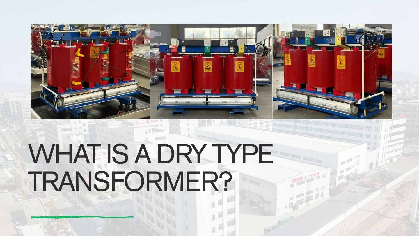
What Is a Dry Type Transformer? A Quick-Start Guide for Beginners
Introduction
A lot of buyers mix up dry and oil-immersed transformers. This can lead to wrong choices, safety hazards, and higher expenditures. This quick-start guide tells you what a dry type transformer is, how it works, and when it’s the best option.
Fundamentals: Definition, Structure, and the Core Safety Principle
PAS lead: Oil systems make people worry about fires, leaks, and frequent checks. These worries make projects take longer and make it harder to find a good place to put them. Dry type transformers get rid of all the oil, giving modern buildings safe, clean, low-maintenance power.
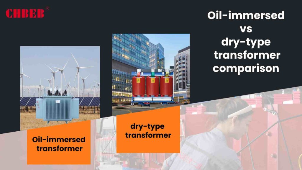
Concept Overview: The Main Difference Between Oil-Based Units and Other Units
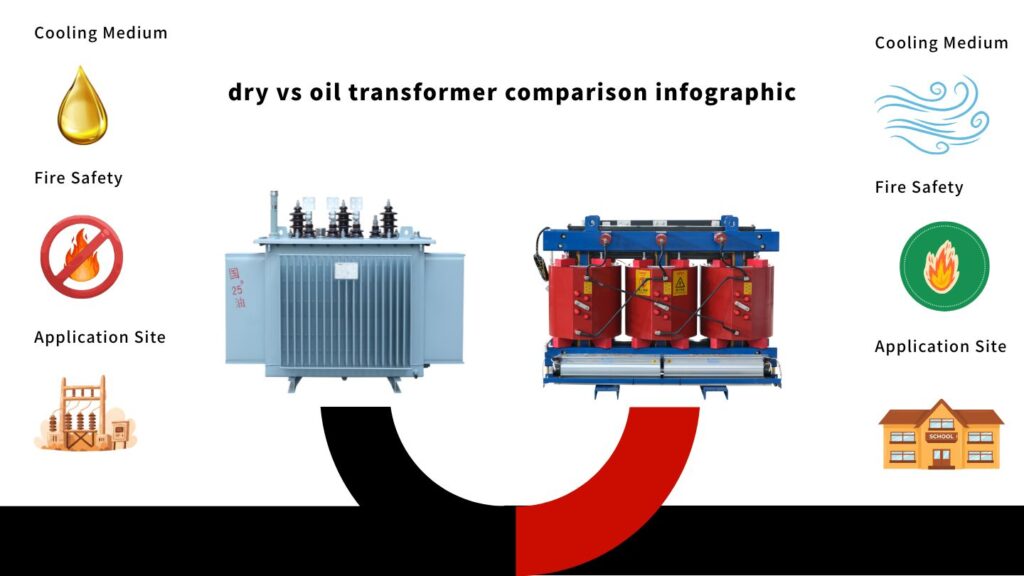
Mineral or ester oil is used to insulate and cool oil-immersed transformers. Air and solid insulation (such varnish or epoxy glue) are used in dry type transformers. Getting rid of liquid lowers the chance of leaks, makes it easier to get building permits, and lowers the amount of fire load in buildings.
| Comparison | Oil-Immersed Transformer | Dry Type Transformer |
|---|---|---|
| Cooling & Insulation | Oil bath; liquid dielectric | Air cooling; solid dielectric |
| Fire Load | Higher (combustible oil) | Very low (no oil) |
| Maintenance | Oil testing, sealing, filtration | Minimal; visual checks, cleaning |
| Typical Placement | Outdoor yards, substations | Indoor rooms, public buildings |
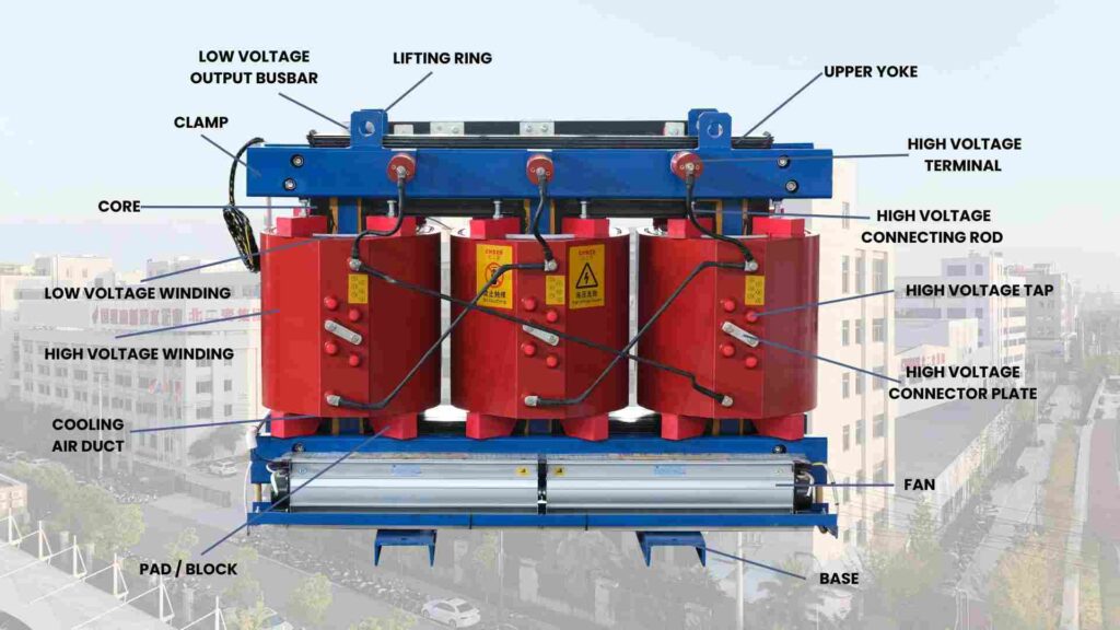
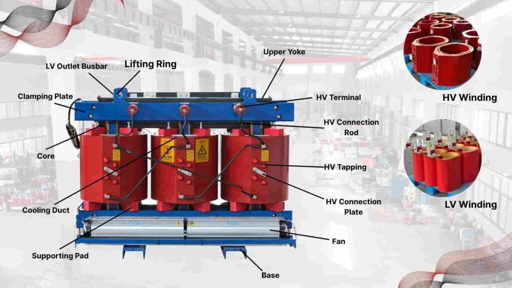
A Look Inside: The Three Main Parts of a Dry Transformer
- Core: Stacks of grain-oriented silicon steel1 make a magnetic channel with minimal loss and stable induction.
- Windings: Copper or aluminum wires that are insulated with varnish or epoxy give the wires dielectric strength and heat resistance.
- Cooling Path: Natural air (AN) or forced air (AF) carries heat away from coils to keep the temperature from going too high.
Result: It runs quietly, regulates itself consistently, and lasts a long time, all without having to deal with oil or spills.
The Value Proposition: Core Benefits and Internal Types
PAS lead: A lot of people are afraid that not using oil will make them less productive. That doubt can stop safer updates. Modern dry kinds fulfill the same performance standards, but they are safer, more sustainable, and easier to use every day.
Three Big Benefits: Safety from Fire, Eco-Friendliness, and the Fact That It Doesn’t Need Any Maintenance
- No combustible oil means a lot less fire load and easier indoor fire safety architecture.
- Eco-Friendliness: No oil leaks or trash; green buildings are easier to follow environmental rules.
- Low Maintenance: No sampling or filtration; regular checks focus on cleanliness, ventilation, and terminations.
| Benefit | What It Means | Impact |
|---|---|---|
| Safety | Minimal fire and spill risk | Better fit for hospitals, schools, transit, data centers |
| Environment | No oil handling or contamination | Smoother approvals; fewer mitigation systems |
| Operations | Simpler inspections and cleaning | Lower OPEX and downtime over service life |
A Simple Explanation of the Key Selection Difference Between VPI and Cast Resin
It depends on the environment, the job, and the budget whether to use VPI or cast resin. This short guide will help you match type to risk and performance.
| Feature | VPI (Vacuum Pressure Impregnated) | Cast Resin (Epoxy Encapsulated) |
|---|---|---|
| Insulation System | Varnish impregnated windings | Solid epoxy cast coils |
| Moisture Resistance | Good | Excellent (suited to humid/coastal) |
| Mechanical Strength | Good | Very high; robust under short-circuit stress |
| Typical Use | Commercial/light industrial indoors | Heavy-duty, harsh, or corrosive sites |
| Budget Sensitivity | Generally lower CAPEX | Higher CAPEX; lower risk in tough sites |
Quick tip: If you’re on a tight budget, go with VPI for interior projects. If you’re worried about humidity, pollution, or mechanical stress, go with cast resin.
Decision Making: Dry vs. Oil—When and Why to Choose Dry?
PAS lead: The price up front typically makes people buy oil. That choice can incorporate fire systems, spill controls, and service that happens on a regular basis. Dry type units take away those problems, which helps keep budgets in check for the life of the asset.
The Ultimate Trade-Off: Weighing Cost, Capacity, and Maintenance
| Parameter | Dry Type Transformer | Oil-Immersed Transformer |
|---|---|---|
| Initial Cost | Often higher | Often lower |
| Maintenance | Minimal; no oil handling | Oil testing, sealing, filtration |
| Cooling Efficiency | Moderate (AN/AF) | High (oil convection) |
| Fire/Spill Risk | Very low | Present; requires mitigation |
| Best Fit | Indoor, public, renewables, metro | Outdoor yards, high-capacity substations |
Use dry type when you want to keep fire load to a minimum, installations are indoors or in public places, and you want low lifetime maintenance.
When outside nameplate capacity and cooling performance are more important than extra safety measures and service routines, use oil-immersed
.
Frequently Asked Questions (FAQ)
1. What is a dry type transformer?
A dry type transformer transfers electrical energy using air or resin insulation instead of oil. It’s clean, safe, and ideal for indoor or fire-sensitive environments such as hospitals, offices, and renewable projects.
2. What’s the difference between dry type and oil-immersed transformers?
Oil-immersed transformers use insulating oil for cooling and insulation, while dry type units rely on air or solid resin. Dry transformers are safer, require less maintenance, and can be installed indoors.
3. Can a dry type transformer catch fire?
It’s extremely unlikely. Dry type transformers use non-flammable materials such as epoxy resin or air insulation, eliminating the fire and explosion risks linked to oil-immersed designs.
4. Do dry type transformers need maintenance?
They require minimal maintenance. Routine inspections focus on ventilation, dust removal, and terminal tightening—no oil testing or replacement is needed throughout their service life.
5. Which is better: Cast Resin or VPI dry type transformer?
Both are reliable. VPI is cost-effective for clean indoor environments, while Cast Resin provides superior moisture and mechanical protection in humid or heavy-duty sites.
6. Can dry type transformers be used outdoors?
Yes. When housed in a sealed IP45 or higher-rated enclosure, dry transformers operate safely outdoors, even in humid, coastal, or dusty environments.
7. Why are dry type transformers usually more expensive than oil types?
Their solid insulation and fireproof design raise initial cost, but they save money over time through reduced maintenance, no oil handling, and enhanced safety compliance.
⚙️ CHBEB — Reliable Partner for Dry Type Distribution Transformers

When it comes to dry type transformer manufacturing, CHBEB stands among China’s most experienced and trusted suppliers. With over 60 years of transformer production expertise, the company has mastered both technical precision and global reliability — serving utilities, EPC contractors, and industrial buyers worldwide.
Our Manufacturing Network
CHBEB operates two factories in Wenzhou, one in Nanjing, and a Beijing office, ensuring large-scale production capacity and fast global delivery. Each factory is equipped with advanced VPI and Cast Resin production lines that comply with IEC 600762, ISO9001, and CE standards.
Why CHBEB for Dry Type Transformers:
- High-End Materials: Every unit uses 100% new copper, Class F/H insulation, and premium silicon steel for maximum efficiency.
- Full Testing Assurance: All dry type transformers undergo strict routine and type tests — including insulation resistance, partial discharge, and temperature rise.
- Proven Reliability: CHBEB is a qualified supplier for the State Grid Corporation of China, maintaining a zero-accident record in global projects.
- Fast OEM/ODM Service: From prototype to batch delivery, customized orders can be completed in as little as one week for urgent projects.
- Global Focus: With exports to Russia, Southeast Asia, Africa, and Belt & Road countries, CHBEB supports local distributors and contractors with on-site service and certification assistance.
- Green Manufacturing: Our dry type transformers are designed for fire safety, low noise, and eco-compliance, ideal for hospitals, schools, and renewable energy systems.
💡 Looking for a reliable dry type transformer manufacturer that combines Chinese manufacturing strength with international quality?
👉 Contact CHBEB today at [email protected] or visit www.chbeb-ele.com to get your customized solution or download our full dry type transformer catalog.
Conclusion
Dry type transformers represent the new standard for safe, efficient, and environmentally responsible power distribution.
By eliminating oil, they reduce fire and spill risks while simplifying installation and maintenance — a clear advantage for modern commercial and industrial projects.
When properly designed and certified, VPI and Cast Resin types deliver decades of stable performance with minimal lifetime cost.
For project engineers and procurement managers, the key is to look beyond price tags — true value lies in tested quality, transparent materials, and proven reliability from a trusted manufacturer.
Dry Type Transformer Quote Request Guide: Fast, Accurate, and Expert Procurement Support
Introduction
It shouldn’t be hard or take a long time to get quotes for transformers. A lot of buyers have to wait days merely to acquire partial quotations, which wastes time on the project. CHBEB fixes this by giving you accurate quotes in less than 24 hours through a quick, professional, and open process.
Speed and Accuracy: How to Submit a Quote Request Efficiently
Every hour counts when transformer projects have to meet tight deadlines. Construction or tender submissions can be put on hold if people don’t respond quickly or if they don’t give all the information they need. That’s why CHBEB has designed a simple, engineering-verified approach for quotes that will save you time and make sure everything is correct.
Promise of the Quote Process: We will respond to your price request within 24 hours.
When vendors don’t have a clear plan or don’t grasp the technology, things typically get delayed. When you ask a question at CHBEB, it gets right to our sales team, which is backed by engineers. They will analyze your parameters and provide you a price within 24 hours, guaranteed.
Our workflow:
- Get your question (email, form, or WhatsApp).
- The engineer checks the load, voltage, and design specs.
- Factory certified price and delivery time.
- Sent a PDF quote with shipping options if needed.
💡 Tip: Always attach datasheets, load requirements, or photos of old equipment for a faster match.
Critical Parameter Checklist: Essential Project Information for Accurate Pricing
Prices that are wrong or, even worse, equipment that doesn’t line up are caused by incomplete data. To give a good quote, please give the important design and operating parameters stated below.
| Category | Required Details | Example |
|---|---|---|
| Capacity (kVA) | Rated power output | 1600 kVA |
| Primary Voltage | Input voltage range | 10 kV |
| Secondary Voltage | Output voltage range | 400 V / 415 V |
| Frequency | 50 Hz / 60 Hz | 50 Hz |
| Connection Type | Dyn11, Yyn0, etc. | Dyn11 |
| Cooling Method | AN / AF (natural or forced air) | AN |
| Insulation Class | F / H | F |
| Protection Level | IP23 / IP44 / IP54 | IP23 |
| Installation Site | Indoor / Outdoor | Indoor |
| Standard | IEC 60076 / ANSI / GB | IEC 60076 |
✅ Giving these 10 things will make sure that the design is perfect, the materials are the best they can be, and the final quote is accurate within ±3%.
How We Help You Choose the Right Transformer for Free
It can be hard to choose between different technologies and vendors. CHBEB’s engineers look at your needs and suggest the optimum design for you at no extra cost, taking into account performance, lifetime, and budget.
- How to choose between Cast Resin and VPI.
- Advice on whether to use copper or aluminum for winding.
- Calculating losses, efficiency, and total cost of ownership.
- Comparing insulation and IP ratings for safety on the site.
🧠 The result is that you get not only a quote, but also a technical recommendation that is tailored to the long-term success of your project.
Price Transparency: The Four Core Factors Driving Dry-Type Transformer Cost
A lot of shoppers get confused by hidden markups and unclear prices. CHBEB breaks down every part that affects the final price of your transformer so that the buying process is transparent and fair.
Cost Trade-Offs Between Copper and Aluminum1 and Cast Resin and VPI in Materials and Technology
It could seem like a good idea to choose cheaper materials, but that can hurt performance. The cost, efficiency, weight, and fire safety of each material and insulation scheme are all different.
| Option | Advantages | Considerations | Cost Level |
|---|---|---|---|
| Copper Windings | Higher conductivity, lower losses, better overload capacity | Heavier, higher material cost | $$$ |
| Aluminum Windings | Lower weight, lower initial cost | Slightly higher losses | $$ |
| Cast Resin Insulation | Full encapsulation, moisture & fire resistance | Higher manufacturing cost | $$$ |
| VPI (Vacuum Pressure Impregnation) | Economical, easy maintenance, repairable | Slightly lower insulation grade | $$ |

⚙️ CHBEB customizes solutions by keeping your site’s humidity, temperature, and budget in check to get the best return on investment.
Long-Term View: Analyzing the Efficiency Class and Total Cost of Ownership (TCO)
If you only look at the price you pay, you could not see future costs. Transformer losses make up more than 60% of the total cost over the course of its life. This means that saving energy now will save you money in the long run.
| Efficiency Class | Typical Loss Reduction | Estimated Energy Savings (15 Years) |
|---|---|---|
| Tier I (Standard) | – | – |
| Tier II (Eco-Design) | ≈ 5% | ≈ US $6,000 – 10,000 |
| Tier III (Premium Efficiency) | ≈ 10% | ≈ US $12,000 – 18,000 |
🌍 CHBEB’s engineers will do a free TCO comparison for you to assist you pick the efficiency class that will save you the most money on energy over the long term.
Quality and Service: The Cornerstone of Trust
A low quote doesn’t mean much if the quality and service after the sale aren’t assured. CHBEB builds trust with its clients by using certified quality systems and being open about its after-sales support.
International Certifications: UL, CE, and ISO ensure that the project meets all requirements.
Global initiatives need to be sure of safety and compliance. IEC 600762 says that all CHBEB dry-type transformers must go through type and routine testing, and they all have international certificates that are recognized around the world.
- ISO 9001, ISO 14001, and ISO 45001 are standards for managing quality, safety, and the environment.
- CE and UL certification are required for the EU and North American markets.
- Type-Test Reports: rise in temperature, impulse, noise, and partial discharge.
Service After the Sale:
- Technical support around the clock.
- Help with global logistics and installation.
- Support for spare parts and lifetime advice.
🏆 The State Grid Corporation of China and multinational EPC contractors trust every CHBEB transformer because they are reliable.
CHBEB — Reliable Partner for Distribution Transformers
With over 60 years of transformer manufacturing expertise, CHBEB has established itself as one of China’s most trusted and globally recognized suppliers of dry type and oil-immersed distribution transformers. The company operates two factories in Wenzhou, one in Nanjing, and a technical and export office in Beijing, ensuring strong production capacity, engineering flexibility, and responsive customer service.
Why Global Buyers Choose CHBEB
- Certified Quality & Full Testing: Every transformer is manufactured under IEC 60076 / ISO 9001 standards and 100% factory-tested before shipment—no exceptions.
- 100% New Raw Materials: Premium copper, silicon steel, and insulation components; no recycled or downgraded materials.
- Fast-Track Delivery: Standard units ready in as little as 7 days for urgent EPC or retrofit projects.
- Customization & OEM Flexibility: Tailored voltage ratios, enclosure IP ratings, and cooling systems (AN/AF) to meet local grid and safety codes.
- Proven Reliability: Qualified supplier for the State Grid Corporation of China with a zero-accident operational record.
- Global Support: Experienced in export documentation, CE/CB certification, and on-site inspection support for clients in the Middle East, Africa, Southeast Asia, and CIS.
Whether you’re designing a hospital, data center, or renewable energy facility, CHBEB can provide a transformer that reduces installation complexity, minimizes lifetime cost, and ensures compliance with international standards.
👉 Looking for a partner who combines Chinese manufacturing strength with global engineering standards? Contact CHBEB for a tailored technical proposal or download our full catalog today.
💬 FAQ Section
Frequently Asked Questions (FAQ)
1. How long does it take to receive a dry-type transformer quote?
Usually within 24 hours after we receive your complete parameters. Our engineers immediately verify the data and confirm price and lead time for accuracy.
2. Which parameters have the biggest impact on transformer pricing?
The most important are capacity (kVA), high/low voltage, winding material (copper or aluminum), insulation method (VPI or cast resin), and the protection level or installation environment.
3. What’s the price difference between copper and aluminum windings?
Copper transformers are typically 15–25% more expensive, but they offer higher efficiency and overload capacity. CHBEB helps balance performance and budget for your project.
4. Do you provide UL-certified dry-type transformers?
Yes. CHBEB supplies transformers with UL, CE, ISO 9001, and IEC 60076 compliance — suitable for both EU and North American engineering projects.
5. Can you help me calculate the capacity if I’m not sure?
Absolutely. Just share your equipment list, load type, or site photos, and our engineers will calculate the optimal capacity and connection scheme for free.
6. Is a cast resin transformer more expensive than a VPI type?
Generally, yes — about 10–20% higher due to its superior fire resistance and moisture protection. CHBEB recommends the best option depending on your site conditions.
7. What is the delivery time for dry-type transformers?
Standard models are ready within 15–25 days. Customized units depend on capacity and specifications; all lead times are clearly stated in your quotation.
Conclusion
Choosing the right transformer is about more than voltage — it’s about long-term safety, reliability, and total cost of ownership.
Dry type distribution transformers offer a proven solution for modern projects that demand fire safety, easy maintenance, and environmental compliance. When selected and engineered correctly, they deliver decades of stable performance with minimal lifetime cost.
For buyers comparing China’s top transformer suppliers, the key is to look beyond catalog prices and focus on certified quality, full testing, and transparent materials — the true indicators of long-term value.
Unveiling the Science of Electromagnetic Induction: The Secret Conversion of Electrical and Magnetic Energy
Introduction
Power doesn’t just happen; it has to be made. Generators and transformers work because changing magnetic fields make voltage and current. This guide makes things clear by explaining how induction works and how engineers make it work better.
The Scientific Foundation: History, Definition, and Core Laws
When magnetism and electricity seem abstract, things get confusing. It gets worse when we can’t “see” fields. The solution is a simple frame: induction happens when the magnetic flux varies, which is controlled by Faraday and directed by Lenz.
Concept Overview: What is Electromagnetic Induction? (The Key is a Changing Field)
When a magnetic flux changes via a conductor loop, it creates an electromotive force (EMF). This is called electromagnetic induction. The change, not the magnetism itself, makes electrons move.
E = − dΦ/d1t, where E is the induced EMF and Φ is the magnetic flux (Webers). This is how motors, generators, and transformers work.
Governing Principles: A Simple Explanation of Faraday’s and Lenz’s Laws
- Faraday’s Law: The amount of induced EMF is equal to the rate at which the magnetic flux through the circuit changes.
- Lenz’s Law says that the direction of the induced current goes against the change that caused it, which keeps energy from being wasted.
Together, they show why moving magnets, changing currents, or rotating coils can make electricity that can be used—there is no perpetual motion, simply conversion.
Real-World Power: The Two Pillars of Induction Technology
Until it turns a turbine or powers a metropolis, theory seems far away. Induction is made possible by two things: generators that create electricity and transformers that change the voltage.
Energy Pillar 1: The Generator—How Mechanical Motion Becomes Electricity
When you turn coils inside a magnetic field (or the field around coils), the flux varies all the time, which causes voltage to build up each time. Higher EMF comes from faster rotation and stronger fields.
| Type | Energy Input | Electrical Output | Typical Uses |
|---|---|---|---|
| AC Generator (Alternator) | Turbine rotation (steam, gas, hydro, wind) | Alternating current (AC) | Utility power stations, wind farms |
| DC Generator | Mechanical rotation + commutator | Direct current (DC) | Legacy DC systems, special drives |
Faraday’s principle in action: mechanical power changes the flux, which causes an EMF.
Energy Pillar 2: The Transformer—Voltage Scaling and the AC/DC Limitation
A transformer employs alternating current (AC) in the main coil to generate a magnetic field that changes over time in a common core. This causes voltage to flow in the secondary coil.
Ideal Relation: V₁ / V₂ = N₁ / N₂. The step-up or step-down factor is determined by the turns ratio2.
Why only AC? Flux stays constant under direct current (DC), so no electromotive force (EMF) is induced. That’s why AC is the primary form of electricity for long-distance transmission and local distribution.
👉 Learn more: Dry vs Oil Transformer Comparison
Engineering Challenges: Losses, Efficiency, and Modern Optimization
Real cores and conductors lose energy as heat and sound. Those losses make things less efficient and shorter. Engineers use materials, geometry, and process control to make them as small as possible.
Efficiency Barriers: Understanding and Minimizing Eddy Current and Hysteresis Losses
| Loss Type | What Causes It | Impact | Modern Mitigation |
|---|---|---|---|
| Eddy Current Loss | Circulating currents in conductive cores under changing flux | Heat, lower efficiency | Laminated grain-oriented silicon steel; thin sheets; insulation coatings |
| Hysteresis Loss | Energy to realign magnetic domains each cycle | Heat during reversals | Low-loss steel grades; optimized flux density; proper frequency selection |
| Copper (I²R) Loss | Conductor resistance in windings | Thermal stress, efficiency drop | High-conductivity copper/aluminum; larger cross-section; lower temperature rise |
| Stray & Structural Loss | Leakage flux, vibration, imperfect geometry | Noise, hot spots | Finite-element design, bracing, VPI, careful layout |
Design levers include core material selection, lamination thickness, turns-per-volt, flux density, cooling method, and manufacturing precision (cut quality, step-lap joints, VPI).
👉 Learn more: Transformer Core Materials Guide · Transformer Maintenance Checklist
CHBEB — Reliable Partner for Distribution Transformers
With over 60 years of transformer manufacturing expertise, CHBEB has become one of China’s most trusted distribution transformer suppliers. The company operates two factories in Wenzhou, one in Nanjing, and an office in Beijing, ensuring both strong production capacity and responsive customer support.
What makes CHBEB stand out:
- Strict Quality Commitment: All raw materials are 100% new and high-grade — no recycled or downgraded components.
- Proven Reliability: A qualified supplier for the State Grid Corporation of China, with a spotless record of zero major accidents.
- 100% Product Testing: Every unit is fully tested before delivery to guarantee safety, efficiency, and long service life.
- Fast-Track Orders: Ability to fulfill urgent orders in as little as one week, helping customers meet tight project deadlines.
- Custom Inventory Planning: Flexible stocking and supply strategies designed to align with customer procurement schedules.
- Global Outlook: Rooted in China and expanding worldwide, CHBEB actively supports local agents and partners, including assistance with market-specific certifications.
- Flexible Customization: Tailored transformer designs for utilities, contractors, and industrial clients, with reliable quality and fast delivery.
👉 Looking for a distribution transformer manufacturer that combines Chinese manufacturing strength with international standards?Contact CHBEB for a tailored solution or Download our full transformer catalog here.
📽️ Watch how CHBEB transformers are designed, assembled, and tested to meet IEC 60076 and global standards.
Conclusion
Electromagnetic induction is more than theory — it’s the foundation of every reliable transformer and power system. Understanding how changing magnetic flux creates voltage helps engineers and buyers recognize what truly defines performance: low loss, high efficiency, and long service life.
By selecting the right core materials, optimizing winding design, and managing eddy and hysteresis losses, projects can achieve measurable energy savings and stable grid operation over decades.
If you’re planning a new distribution or renewable energy project and want to improve efficiency, cost stability, and transformer reliability, our engineering team at CHBEB can help you apply these principles in practical designs built to IEC 60076 standards.
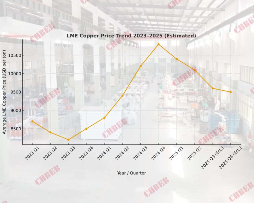
Introduction:
In 2025, the price of copper is expected to reach new highs. Manufacturers and purchasers of transformers should brace themselves for tighter budgets and increasing material costs. Read this article to learn how to adjust and safeguard your project expenses in the face of the rising demand for copper caused by the energy transition.
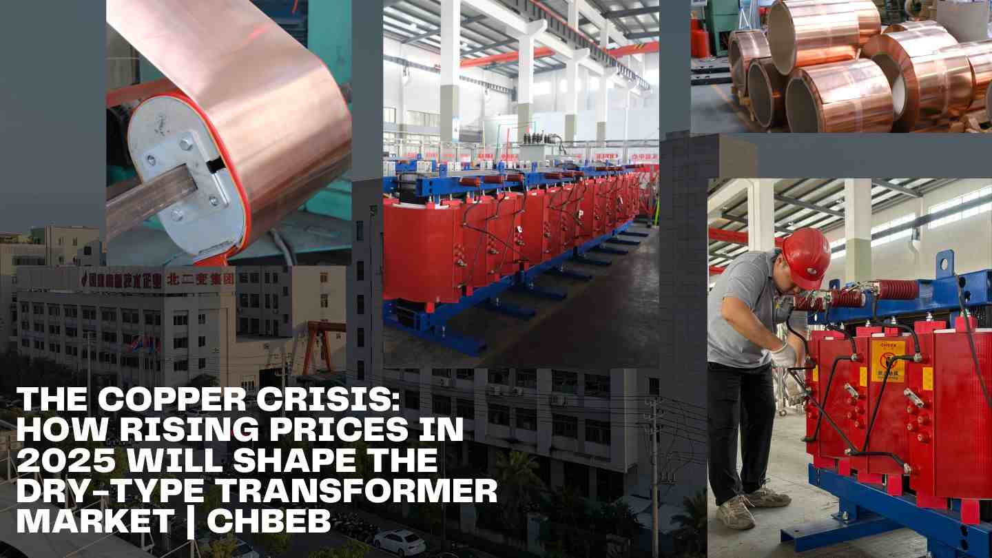
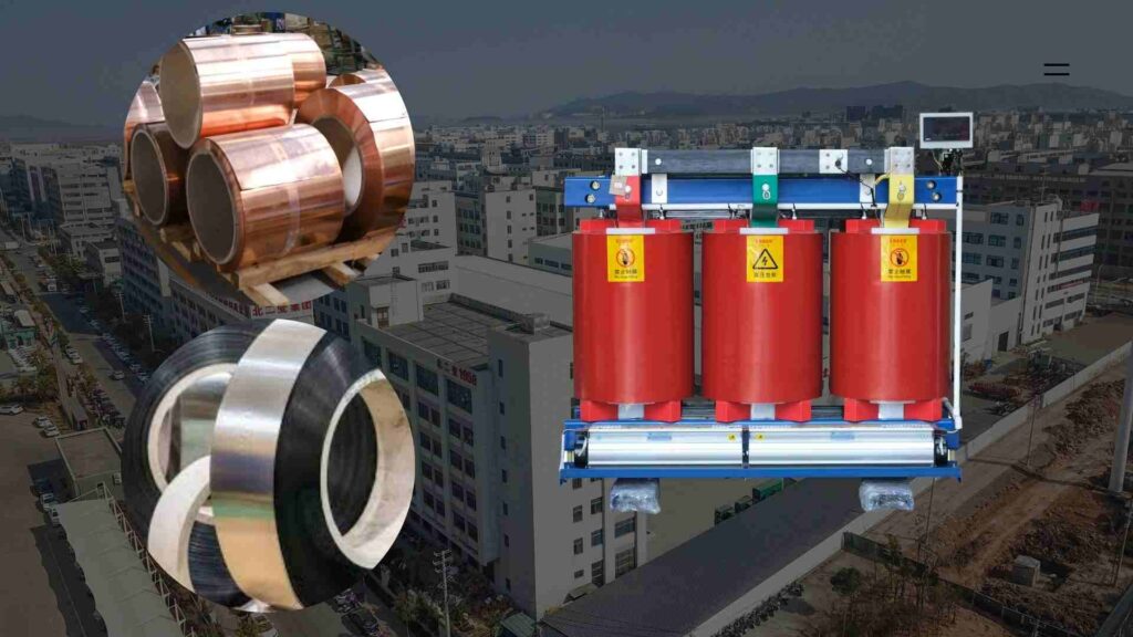
The Direct Hit: Copper’s Crucial Role in Transformer Costs
The cost to make a transformer goes up the minute the price of copper goes up. Due of its central role in winding, even a little change in copper prices1 can have a significant impact on project finances.
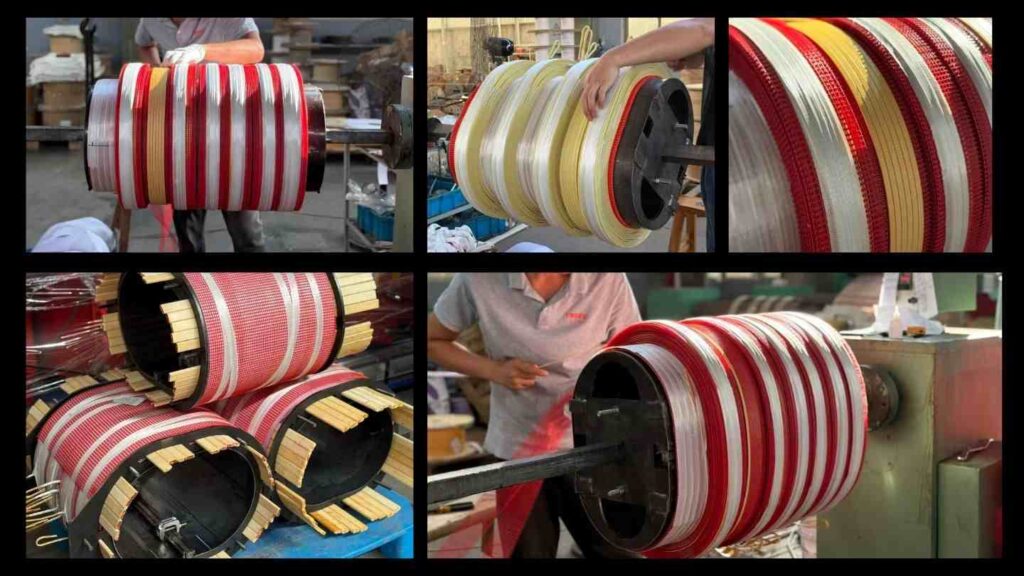
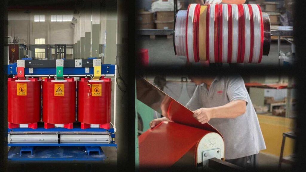
🎥 CHBEB Copper Winding Process: Precision winding, pure copper conductors, and tight tension control — ensuring low loss and high efficiency in every transformer.
Assessing the Effect: The Role of Copper in Total Unit Cost
Copper is the most expensive material in a dry-type transformer, making up 35–45% of the total. An additional 2-4 percent to the final price per unit is added for every 10% rise in copper prices.
| Component | % of Total Cost | Cost Sensitivity | Notes |
|---|---|---|---|
| Copper Windings | 35–45% | High | Main cost driver, fluctuates with global metal prices |
| Core Steel (GOES) | 25–30% | Medium | Stable but rising due to grid expansion |
| Resin & Insulation | 10–15% | Low | Prices remain stable |
| Labor & Assembly | 10–20% | Medium | Depends on region and plant automation |
In a nutshell, copper is both the most important and most difficult to manage variable cost in transformer production.
Factors Influencing the Market: The Rising Cost of Copper Due to Renewable Energy
Electromagnetic fields are increasing the demand for copper. Copper is used three to five times more per megawatt for renewable projects, electric vehicle infrastructure, and smart grid enhancements. Copper will remain in short supply until at least 2025–2027 since new mines take a long time to open.
Strategic Adaptation: Evaluating Aluminum and Mitigating Costs
Manufacturers and customers are looking into aluminum windings2 as a way to minimize costs without compromising performance, especially with the recent spike in copper prices.
A Comparison of Copper and Aluminum (Price vs. Size): The Great Trade-Off
Although aluminum has a little poorer conductivity, it is less expensive up front. Your project’s kind, efficiency goals, and available area for installation will determine which one is best.
| Attribute | Copper Windings | Aluminum Windings |
|---|---|---|
| Conductivity | 100% | ~61% of copper |
| Weight | Heavier | ~40% lighter |
| Size for same kVA | Compact | 10–20% larger |
| Cost per unit | Higher | 20–30% lower |
| Thermal Expansion | Low | Higher (requires tighter joints) |
| Efficiency | Slightly higher | Slightly lower |
| Maintenance | Stable | Needs regular inspection |
Though it reduces prices, aluminum has the potential to increase energy losses and footprint. The overall economics of the project determine the optimal balance.
How Buyers Can Manage Price Volatility in Procurement Strategies
Project margins can be broken if copper price volatility is disregarded. As a precaution, smart procurement teams do the following:
- Set quotations with a validity period of 30-60 days and lock in rates early.
- Mix up your materials by thinking about aluminum and copper.
- Arrange for modular shipments and vary their arrival dates to control cash flow.
- Keep an eye on London Metal Exchange trends to foretell when prices will rise and fall.
- Think about efficiency, longevity, and OPEX as part of total ownership cost (TOC).
- .
👉 Learn more: Dry vs Oil Transformer Comparison
Long-Term Outlook: Efficiency Standards and Future Pricing
The worldwide trend toward efficiency standards that prioritize high-performance designs reliant on conductive materials will persist even if copper prices level out.
The Lifespan Cost: The Efficiency Penalty of Cheaper Materials
Transformer losses can be increased by using cheaper materials. The total cost of ownership increases by hundreds of kilowatt-hours for every 1% decrease in efficiency due to lifetime energy waste. Reduced losses over 25-30 years allow efficient copper-based designs to recoup their higher initial price.
Important notice for regulators: transformers are now mandated to reach efficiency criteria of IE2-IE3 by the EU EcoDesign regulation and IEC 60076, which means that essential infrastructure cannot use materials with low conductivity.
CHBEB — Reliable Partner for Distribution Transformers
With over 60 years of transformer manufacturing expertise, CHBEB has become one of China’s most trusted distribution transformer suppliers. The company operates two factories in Wenzhou, one in Nanjing, and an office in Beijing, ensuring both strong production capacity and responsive customer support.
What makes CHBEB stand out:
- Strict Quality Commitment: All raw materials are 100% new and high-grade — no recycled or downgraded components.
- Proven Reliability: A qualified supplier for the State Grid Corporation of China, with a spotless record of zero major accidents.
- 100% Product Testing: Every unit is fully tested before delivery to guarantee safety, efficiency, and long service life.
- Fast-Track Orders: Ability to fulfill urgent orders in as little as one week, helping customers meet tight project deadlines.
- Custom Inventory Planning: Flexible stocking and supply strategies designed to align with customer procurement schedules.
- Global Outlook: Rooted in China and expanding worldwide, CHBEB actively supports local agents and partners, including assistance with market-specific certifications.
- Flexible Customization: Tailored transformer designs for utilities, contractors, and industrial clients, with reliable quality and fast delivery.
👉 Looking for a distribution transformer manufacturer that combines Chinese manufacturing strength with international standards?Contact CHBEB for a tailored solution or Download our full transformer catalog here.
🎥 Take a tour of CHBEB — our manufacturing capabilities, quality control, and global vision.
Conclusion
The copper price surge of 2025 is reshaping how dry-type transformers are designed, manufactured, and procured. Buyers and engineers can no longer focus only on upfront cost — long-term efficiency, material stability, and lifecycle performance now define real project value.
While copper remains the premium choice for high-efficiency designs, aluminum windings can offer a practical alternative for medium-load or budget-sensitive projects when properly engineered to IEC 60076 and EU EcoDesign IE2–IE3 standards.
The best strategy for 2025 and beyond is to combine material diversification, short-term price locking, and long-term efficiency planning. In the end, the most cost-effective transformer isn’t always the cheapest — it’s the one that maintains stable performance, meets efficiency regulations, and minimizes total ownership cost over decades of operation.
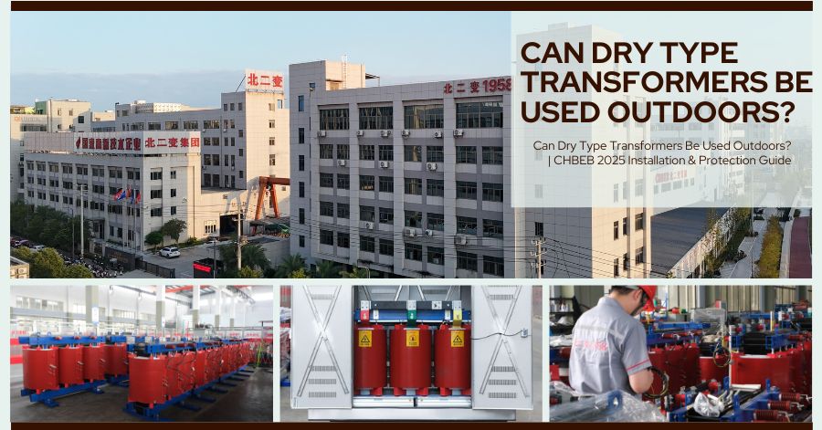
Introduction
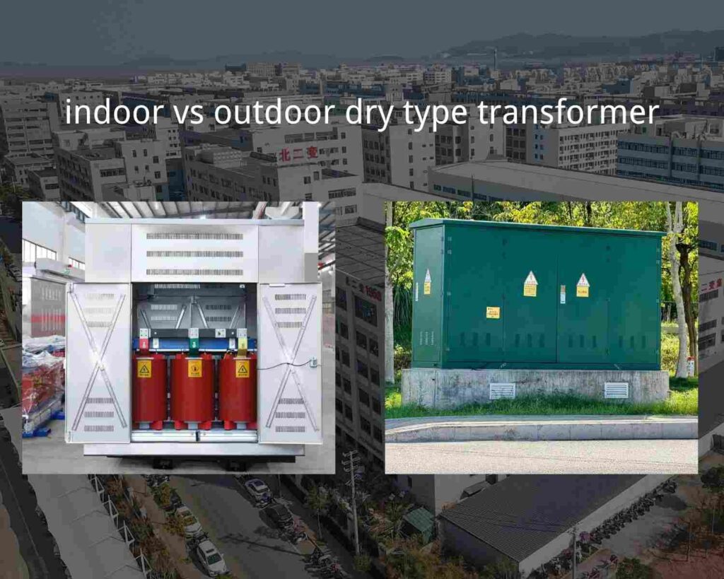
A lot of project engineers and procurement managers want to know if dry-type transformers may be utilized outside.
Yes, but only if the conditions are correct. People like dry-type transformers because they are safe, good for the environment, and easy to take care of. However, they need air to cool and insulate them. This makes them more vulnerable to weather, humidity, and dust, especially while they are outside.
This article gives an unbiased, engineering-based look at how dry-type transformers can be used safely outside, what safety criteria they need to meet, and how to pick the right manufacturer for your project.
1. What Is a Dry-Type Transformer?
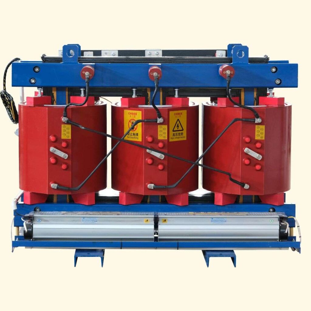
Instead of oil, a dry-type transformer employs air or solid insulation, like cast resin epoxy or the VPI process. They are great for:
- Schools, hospitals, and businesses
- Substations that are underground or in a building
- Solar, wind, and hydro power are all examples of renewable energy systems.
The same “dry” design that makes it safer inside also means that you need to protect it properly outside to make sure it works and lasts.
2. Outdoor Use Depends on Enclosure Protection (IP Rating)
Whether a dry-type transformer can be used outdoors depends primarily on its enclosure rating — measured by the IP (Ingress Protection) code1, which defines the transformer’s resistance to dust and moisture.
| IP Rating | Environment | Protection Level |
|---|---|---|
| IP20–IP23 | Indoor use | Protection against solid objects and limited moisture |
| IP44–IP45 | Semi-outdoor | Splash-resistant, suitable for covered or ventilated areas |
| IP54–IP55 | Outdoor | Dust-tight and rainproof, suitable for open-air installation |
Recommendation: Choose enclosures with an IP45 rating or greater for outside use. For very harsh climates, IP55 is best.
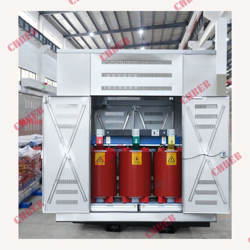
3. Key Design Requirements for Outdoor Operation
- Weatherproof case: Stainless steel or powder-coated case that won’t rust, become dusty, or get UV rays.
- Ventilation system: either natural or forced-air cooling to keep things from being too hot.
- Humidity control: Put space heaters or dehumidifiers inside the cabinet to keep condensation from forming.
- A good foundation is an elevated concrete plinth with drainage to keep water from pooling.
- Check the air filters, insulation resistance, and grounding every so often.
These steps safeguard the windings and core from stress from the outside world, which makes the transformer last longer.
4. Typical Outdoor Applications
Outdoor-rated dry-type transformers are becoming increasingly common in areas where oil-filled Outdoor-rated dry-type transformers are becoming more common in places where oil-filled units are not allowed for reasons of safety or environmental protection.Some of these places are:
- Solar farms and wind substations, which are examples of renewable energy plants
- Substations and transformers erected on pads in cities
- Public infrastructure such as metro systems and tunnels
- Industrial areas with tight fire safety regulations
Their oil-free and fire-resistant design makes them safe against fire and oil hazards, allowing their use in hazardous or environmentally sensitive locations.
5. International Standards and Compliance
- IEC 60076-112 — Sets up environmental classes (E2, C2, F1) for how things behave in different levels of wetness, climate, and fire.
- IEEE C57.12.01—General requirements for dry-type power and distribution transformers.
- ANSI/NEMA 250: Standards for protecting electrical enclosures (Type/IP equivalency).
Following these rules makes it possible for the system to work reliably even in tough outside situations.
6. Advantages of Outdoor Dry-Type Transformers
| Feature | Advantage |
|---|---|
| Fire safety | No flammable oil; suitable for public spaces |
| Eco-friendly | No oil leaks or contamination risk |
| Compact design | Easier to install in urban or confined areas |
| Low maintenance | No need for oil sampling or refilling |
| Customizable protection | Available with IP45–IP55 enclosures for different environments |
7. Limitations to Consider
- Costs more upfront than oil-immersed varieties
- Lower range of power capacity, usually less than 10 MVA
- Managing heat in sealed enclosures is more complicated.
Oil-immersed transformers may be more cost-effective for large-scale transmission or high industrial loads.
8. Choosing the Right Supplier — Balancing Quality, Cost, and Delivery
Choosing a transformer isn’t just about its technical specifications; it’s also about finding the right balance between quality, price, and delivery time.
People around the world recognize that China’s top 10 transformer manufacturers produce well-engineered, durable products with long service life. However, their products are often more expensive and mainly focused on large-scale utility projects.
In contrast, medium-sized transformer factories can offer OEM/ODM customization, competitive pricing, and faster production cycles, making them an excellent choice for EPC contractors, distributors, and regional utilities seeking cost-effective solutions.
When selecting a supplier, always check their certifications (ISO, IEC, CE), testing capabilities (routine, type, and special tests), and material standards (copper conductors, silicon steel, insulation grade). A well-audited manufacturer that follows IEC/IEEE design standards can deliver transformers that perform as reliably as top brands — but at a more efficient cost.
CHBEB — Reliable Partner for Distribution Transformers
With over 60 years of transformer manufacturing expertise, CHBEB has become one of China’s most trusted distribution transformer suppliers. The company operates two factories in Wenzhou, one in Nanjing, and an office in Beijing, ensuring both strong production capacity and responsive customer support.
What makes CHBEB stand out:
- Strict Quality Commitment: All raw materials are 100% new and high-grade — no recycled or downgraded components.
- Proven Reliability: A qualified supplier for the State Grid Corporation of China, with a spotless record of zero major accidents.
- 100% Product Testing: Every unit is fully tested before delivery to guarantee safety, efficiency, and long service life.
- Fast-Track Orders: Ability to fulfill urgent orders in as little as one week, helping customers meet tight project deadlines.
- Custom Inventory Planning: Flexible stocking and supply strategies designed to align with customer procurement schedules.
- Global Outlook: Rooted in China and expanding worldwide, CHBEB actively supports local agents and partners, including assistance with market-specific certifications.
- Flexible Customization: Tailored transformer designs for utilities, contractors, and industrial clients, with reliable quality and fast delivery.
👉 Looking for a distribution transformer manufacturer that combines Chinese manufacturing strength with international standards?Contact CHBEB for a tailored solution or Download our full transformer catalog here.
Conclusion
Yes — dry-type transformers can be safely used outdoors, provided they are properly protected with IP-rated enclosures, well ventilated, and designed in compliance with IEC/IEEE international standards. Their fire safety, low maintenance, and eco-friendly operation make them ideal for modern infrastructure, renewable energy, and public utility projects.
When purchasing, remember that “best” doesn’t always mean “most expensive.” While high-end brands deliver proven reliability, medium-sized, IEC-certified manufacturers often provide faster delivery, flexible customization, and a lower total project cost — without compromising on technical quality.
Ultimately, the right transformer is the one that matches your project’s environment, voltage class, safety requirements, and budget — ensuring stable, efficient, and long-term performance for years to come.
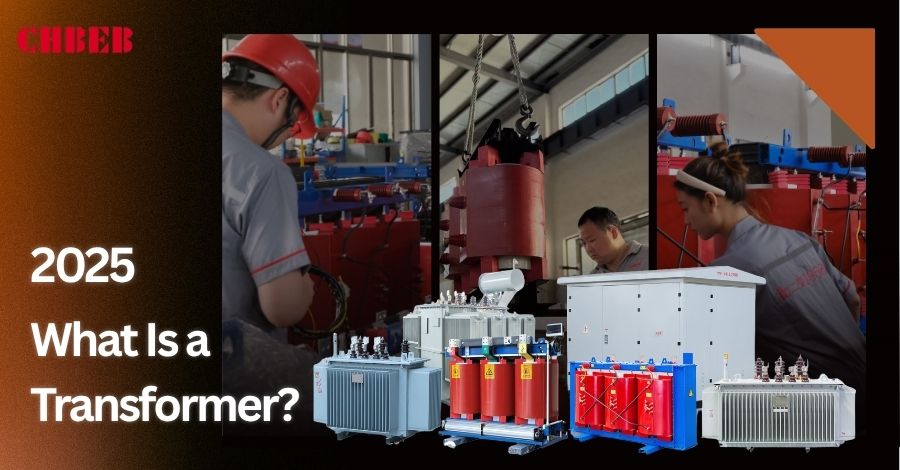
What Is a Transformer? A Beginner’s Guide to the Heart of the Power Grid
Introduction
A transformer is always working quietly behind the scenes when you turn on a light, charge your phone, or walk through a city glowing at night.
It doesn’t create electricity — it makes it useful. By converting high voltage from large power stations into safe, stable levels, transformers connect the power grid1 to our everyday world.
Inside, coils of copper and a magnetic core perform a precise dance of electromagnetic induction2, transferring energy without contact — efficiently, silently, and endlessly.
In short, transformers are the hidden link that keeps modern life running — the reason electricity flows where and how we need it.
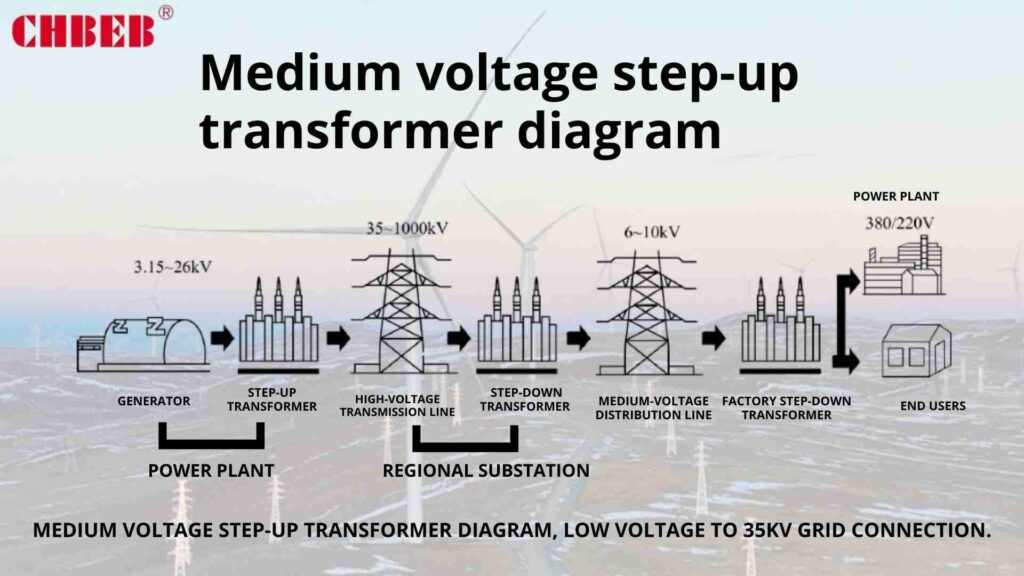
The Transformer’s Job: What It Does and Why We Need It
Power leaves the plant at a very high voltage so it may go a long way. A transformer increases the voltage up or down as needed so that you can use it safely.
The Simple Definition: Why We Can’t Use Electricity Straight from the Plant
High voltage is useful for sending power, but it’s too dangerous for households. A transformer raises the voltage so it can move more easily and lowers it so that buildings and gadgets can use it securely.
How It Works: The “Invisible Bridge” of Electromagnetism
Inside, there are two wire coils encircling a metal core. An electromagnetic bridge with no moving parts is created when current flows through the first coil and forms a magnetic field that causes voltage to flow through the second coil. The output voltage is set by the coil turns ratio.
Anatomy and Application: Types of Transformers You See Every Day
Knowing the key parts and common types can help you choose the best, safest, and most efficient option.
The Basic Parts: The Core, Primary Coil, and Secondary Coil
- Core: Silicon-steel “heart” that directs magnetic energy.
- The primary coil takes in the electricity that comes in.
- The secondary coil sends out the changed voltage.
- Insulation and enclosure: Keep everything safe and apart.
- Cooling: Air (dry type) or oil/ester (liquid-filled) takes away heat.
Step-Up vs. Step-Down: The Difference Between Power Plants and Your Phone Charger
- Step-up: Increases the voltage near power plants so that electricity can flow farther with less loss.
- Step-down: This lowers the voltage at substations and buildings so that they can be used safely every day. This includes the small transformer in your phone charger.
Dry vs. Oil: Understanding the Two Main Types and Where They Are Used
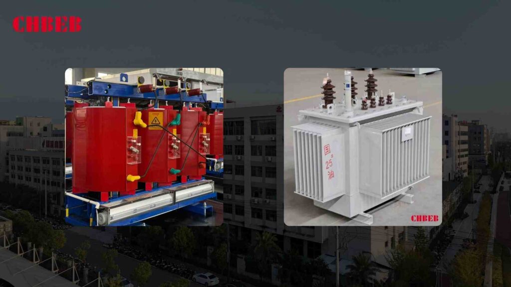
- Dry-type (air-cooled): Used inside malls, hospitals, and offices. Simple to put together and take care of.
- Oil-immersed (liquid-filled): Used outside in substations, factories, and solar and wind farms. Esters make fire and environmental performance better; oil cools and insulates for larger loads.
👉 Learn more: Oil-Immersed Transformer Guide · Dry vs Oil Transformer Comparison
Practical FAQs: Understanding Transformer Efficiency and Safety
Fast answers to the questions purchasers ask most often.
Common Questions: Efficiency, Noise, and Transformer Lifespan
Do transformers work well?
Yes, most of them work at 97–99% efficiency. Small losses just make heat.
What makes transformers hum?
The 50/60 Hz magnetic field makes the core vibrate a little (magnetostriction). Good silicon steel and a tight fit make less noise.
How long do they stay?
Transformers that are submerged in oil last roughly 25 to 35 years.
Dry-type transformers last roughly 20 to 25 years, depending on how much load they have and where they are.
Are they safe?
Yes, as long as they are the right size, placed correctly, and protected (with fuses, breakers, grounding, and the right enclosures). Liquid units have bunds, spill control, and fire safety features.
Do they need to be taken care of?
Type of dry: Check connections and keep vents clean.
Filled with oil: Check the gaskets, clean the radiators, and test the oil for moisture, acidity, breakdown voltage, and DGA.
👉 Learn more: Transformer Maintenance Checklist
Brand Transformers vs Factory-Direct Transformers: Which Is Better for You?
Buying a famous brand means reliability — but it also means higher prices and longer lead times. Factory-direct transformers, like those from CHBEB, use the same core materials and testing standards — without dealer markups.
| Feature | Brand Transformers | CHBEB Factory Transformers |
|---|---|---|
| Price | Higher (includes brand markup) | Lower — direct from manufacturer |
| Lead Time | Longer — through distributors | Faster — factory to port |
| Customization | Limited standard models | Full customization (voltage, capacity, enclosure) |
| After-Sales | Handled by third-party agents | Direct engineering support |
| Quality | High and consistent | Meets IEC/IEEE standards with same-grade materials |
IIn short: Each option has its strengths — branded transformers offer proven reliability, while factory-direct transformers balance quality with faster lead times and lower costs. The final choice depends on project priorities such as budget, delivery time, and specification flexibility.
CHBEB — Reliable Partner for Distribution Transformers
With over 60 years of transformer manufacturing expertise, CHBEB has become one of China’s most trusted distribution transformer suppliers. The company operates two factories in Wenzhou, one in Nanjing, and an office in Beijing, ensuring both strong production capacity and responsive customer support.
What makes CHBEB stand out:
- Strict Quality Commitment: All raw materials are 100% new and high-grade — no recycled or downgraded components.
- Proven Reliability: A qualified supplier for the State Grid Corporation of China, with a spotless record of zero major accidents.
- 100% Product Testing: Every unit is fully tested before delivery to guarantee safety, efficiency, and long service life.
- Fast-Track Orders: Ability to fulfill urgent orders in as little as one week, helping customers meet tight project deadlines.
- Custom Inventory Planning: Flexible stocking and supply strategies designed to align with customer procurement schedules.
- Global Outlook: Rooted in China and expanding worldwide, CHBEB actively supports local agents and partners, including assistance with market-specific certifications.
- Flexible Customization: Tailored transformer designs for utilities, contractors, and industrial clients, with reliable quality and fast delivery.
👉 Looking for a distribution transformer manufacturer that combines Chinese manufacturing strength with international standards?Contact CHBEB for a tailored solution or Download our full transformer catalog here.
Conclusion
Transformers are the quiet backbone of the modern power grid. They connect high-voltage generation with safe, everyday use, making electricity usable, reliable, and efficient. By understanding how they work, their types, and their construction, engineers and buyers can make informed decisions that ensure long-term reliability and safety.
Whether dry-type or oil-immersed, every transformer serves the same essential purpose: to transmit energy efficiently, minimize losses, and maintain consistent performance. Selecting the right design, verifying compliance with IEC/IEEE standards, and following proper maintenance practices are key to dependable operation and optimal lifecycle cost.
In summary, the best transformer is not defined by its brand but by how effectively it meets your project’s technical, safety, and efficiency requirements — today and for many years to come.
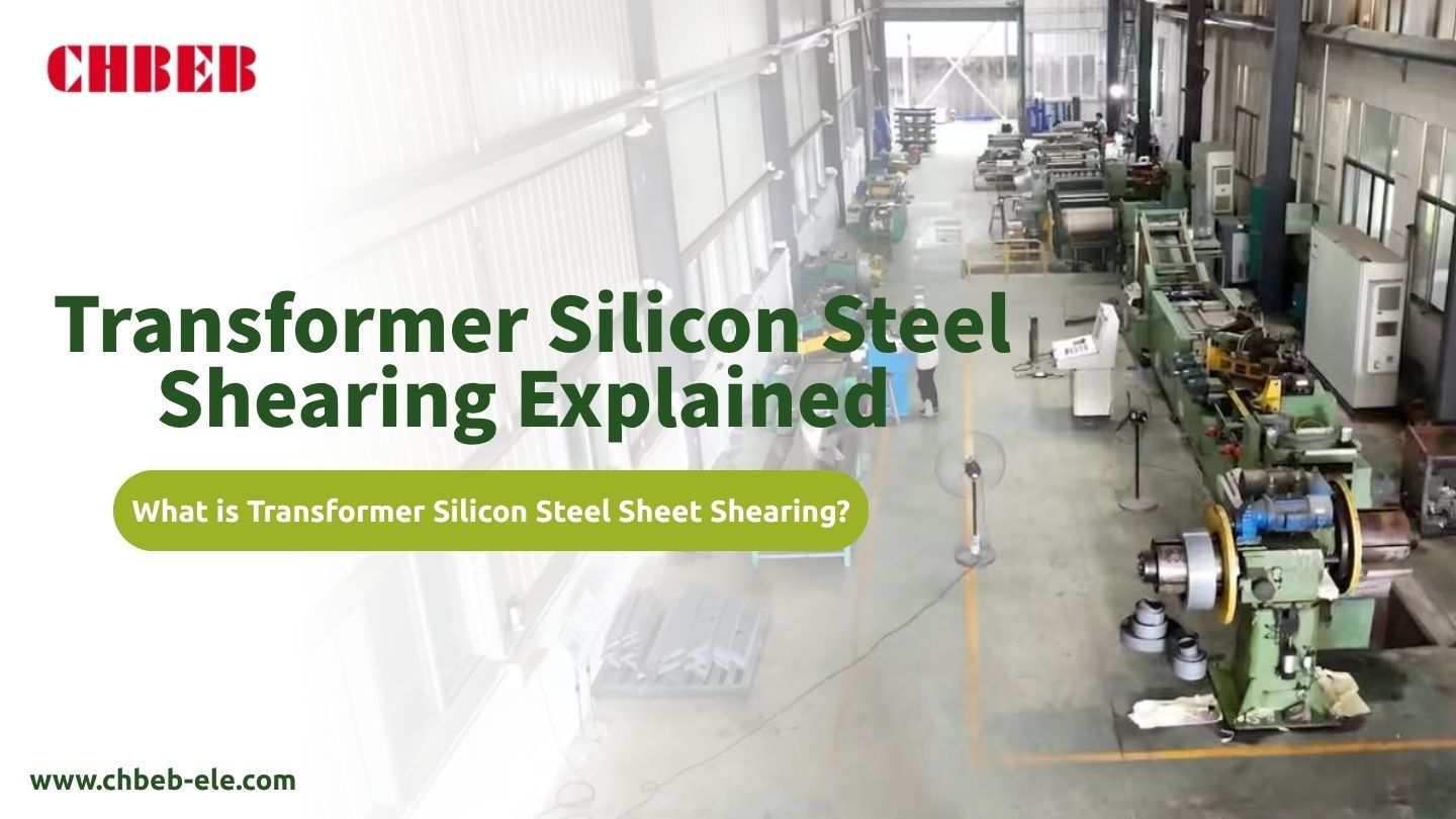
What is Transformer Silicon Steel Sheet Shearing? The Critical Step for Core Efficiency
Introduction
When a transformer hums too loudly or runs too hot, the issue often begins long before electricity ever flows — it starts with how the silicon steel sheets are sheared. Poorly cut transformer laminations create microscopic air gaps and magnetic stress, increasing core loss, noise, and long-term energy consumption.
Precise silicon steel shearing, however, keeps every lamination perfectly aligned with the grain-oriented electrical steel (GOES)1 direction, protecting the insulation coating and ensuring a cooler, quieter, and more efficient transformer core — engineered to perform reliably for decades.
Fundamentals: The Science and Purpose of Silicon Steel Shearing
When cutting is sloppy, the losses go up and the hum increases louder. Exact shearing turns coils into lamination sets that keep the grain orientation, cut down on air gaps, and protect the insulation, which keeps the core’s efficiency.
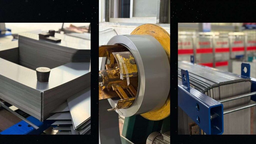
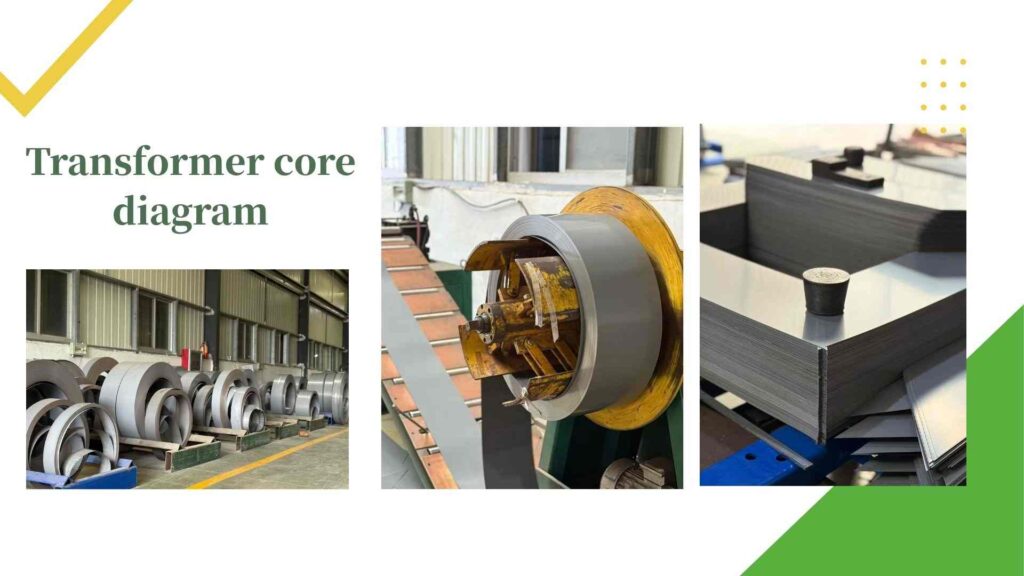
Definition: From Coil to Core Laminations
Example: Silicon Steel Coil to Core Lamination Process
Watch how CHBEB transforms GOES coils into precision-cut laminations — including shearing, punching, and stacking for step-lap transformer cores.
Shearing is the precise cutting of grain-oriented electrical steel (GOES/GOSS) from mill coils into laminations for E-I, C-core, wound-core, or mitered core stacks. Main goals:
- The length, width, window, and miter angles are all exactly right.
- Keep the inorganic insulation intact to avoid inter-lamination eddy currents that can damage the coating.
- Grain alignment: The flux follows the direction of rolling to lower the magnetizing VA.
- High stacking factor: flat, even laminations fit firmly together with very little air trapped inside.
Typical flow: uncoil, cut, shear/miter punch, notch/holes, deburr/clean, and sort and stack (step-lap plan). For wound cores, strip slitting and winding take the role of discrete cutting, but the standards for edge integrity stay the same.
The “Why”: How Cutting Quality Directly Impacts Core Losses and Noise
Cutting can harm the edge microstructure by making burrs, work-hardening, and microcracks. These make local flux detours and hidden air gaps, which makes:
- Loss at no load (P₀): extra core loss from hysteresis and eddy currents caused by poor silicon steel shearing at stressed edges.
- Exciting current: more VA is required to magnetize the transformer core.
- Magnetostriction noise: mechanical stress increases the 100/120 Hz transformer hum.
The Manufacturing Precision: Techniques, Technology, and Quality Control
Pressure to produce leads to flaws. Every lamination is exact, flat, and low-stress thanks to disciplined tools, steady procedures, and verifiable quality assurance.
The 45-Degree Secret: Step-Lap Joints and How to Cut Down on Air Gaps
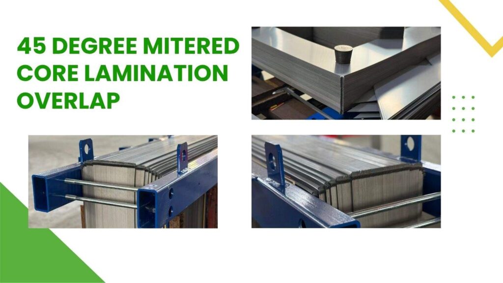
In transformer silicon steel shearing, the 45° mitered joint is not just a design detail—it’s a performance secret.
By combining mitered 45° joints with step-lap stacking2, the air gap at the core joints is distributed across several overlapping steps, allowing magnetic flux to flow more smoothly through the transformer core.
This precision design delivers multiple advantages:
- Lower no-load loss (P₀) and fewer hot spots due to reduced local flux density at the joints.
- Quieter operation, as stress-driven magnetostriction at the corners is minimized.
- Easier assembly, since the gradual overlap reduces mechanical stress and improves core alignment.
👉 The result: tighter magnetic circuits, lower energy loss, and longer-lasting, quieter transformers.
Checklist for good practice:
- Angle accuracy: 45.0° ± 0.1–0.2° (for premium low-loss cores, it should be closer).
- Step pitch control: the length of each step stays the same (for example, 6–20 mm vs. the width of the lamination).
- Overlap sequencing: set lap order (like ABC/ABC) to stop flux gaps from happening.
- Grain direction: line up the direction of the rolling; never flip a piece at the joint.
- Flatness and planarity: tight stacks keep air gaps and buzzing from happening.
Fine-blanking/miter punching (high throughput), CNC miter shear (flexible, precise), and laser (excellent geometry—manage heat-affected zone and think about stress-relief anneal for premium grades) are all ways to cut miters.
Quality Checks: Avoiding Burrs, Damage, and Mechanical Stress
In transformer silicon steel shearing, precision quality control ensures every lamination meets performance standards.
From burr height to surface coating and stack flatness, each metric directly affects core loss, magnetizing current, and noise level in the final transformer core.
1️⃣ Burr Height (Edge Quality)
For distribution transformer cores, burr height should be ≤ 0.02–0.05 mm.
Excessive burrs may bridge laminations and cause inter-lamination shorts, leading to higher eddy current losses and heating.
2️⃣ Tooling and Clearance
Maintain punch/die clearance at 5 – 10 % of material thickness.
Use SPC to monitor the rollover, shear, and fracture zones to detect die wear before it affects edge quality.
3️⃣ Coating Integrity (Surface Resistivity)
Check surface resistivity to confirm that the inorganic insulation coating remains intact.
Never stack laminations that are scratched, oily, or dirty — this can cause partial shorts and higher losses.
4️⃣ Dimensional Accuracy & Miter Angle
Apply vision gauging to verify length/width tolerances (±0.10–0.20 mm) and miter angle accuracy.
Hole and notch alignment keeps assembly stress evenly distributed and prevents frame distortion.
5️⃣ Residual Stress Control
Use low-stress shear parameters, sharp dies, and stress-relief annealing when needed.
Apply controlled torque when clamping frames to prevent additional mechanical strain.
6️⃣ Stacking Factor & Flatness
Compare the actual stack height with the theoretical value to calculate the stacking factor.
Use insulated clamps to compact the stack evenly and minimize trapped air.
7️⃣ Cleanliness Management
Treat the stacking area like a clean zone.
Use vacuum or ionized air to remove chips, dust, and oil film between laminations to avoid micro-air gaps.
8️⃣ Process Data Tracking
Record burr height, angle, dimensions, resistivity, and stacking factor for every lot.
Correlate QA data with no-load loss (P₀) and noise test results of finished cores to trace cause and effect.
👉 Precise quality control during silicon steel shearing is what guarantees long-term transformer efficiency, quiet operation, and minimal power loss.
CHBEB — Reliable Partner for Distribution Transformers
With over 60 years of transformer manufacturing expertise, CHBEB has become one of China’s most trusted distribution transformer suppliers. The company operates two factories in Wenzhou, one in Nanjing, and an office in Beijing, ensuring both strong production capacity and responsive customer support.
What makes CHBEB stand out:
- Strict Quality Commitment: All raw materials are 100% new and high-grade — no recycled or downgraded components.
- Proven Reliability: A qualified supplier for the State Grid Corporation of China, with a spotless record of zero major accidents.
- 100% Product Testing: Every unit is fully tested before delivery to guarantee safety, efficiency, and long service life.
- Fast-Track Orders: Ability to fulfill urgent orders in as little as one week, helping customers meet tight project deadlines.
- Custom Inventory Planning: Flexible stocking and supply strategies designed to align with customer procurement schedules.
- Global Outlook: Rooted in China and expanding worldwide, CHBEB actively supports local agents and partners, including assistance with market-specific certifications.
- Flexible Customization: Tailored transformer designs for utilities, contractors, and industrial clients, with reliable quality and fast delivery.
👉 Looking for a distribution transformer manufacturer that combines Chinese manufacturing strength with international standards?Contact CHBEB for a tailored solution or Download our full transformer catalog here.
Conclusion
Precise silicon steel shearing isn’t just a workshop detail—it’s the foundation of low core loss, quiet operation, and long transformer life. When burrs are controlled, coatings preserved, and 45° step-laps aligned, magnetic flux flows smoothly with minimal energy loss.
For global transformer buyers, shearing quality is a direct indicator of supplier capability. Every 0.01 mm of burr height or misaligned grain direction can raise no-load loss and noise by several percent—affecting both energy bills and reliability.
At CHBEB, precision CNC miter shearing and step-lap core assembly ensure every lamination meets IEC core loss standards before stacking. That’s why CHBEB’s cores stay efficient, quiet, and consistent in projects across the Middle East, Africa, and Southeast Asia.
👉 Learn more: Oil-Immersed Transformer Guide · Dry vs Oil Transformer Comparison · Transformer Maintenance Checklist
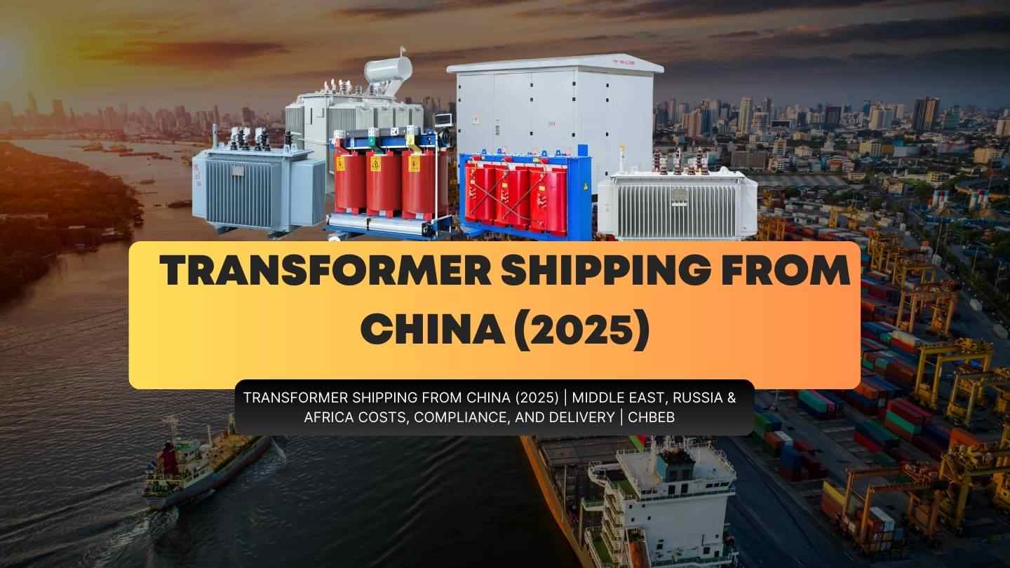
Transformer International Shipping Master Guide: A Five-Step Delivery Process from China to Global Markets
Introduction
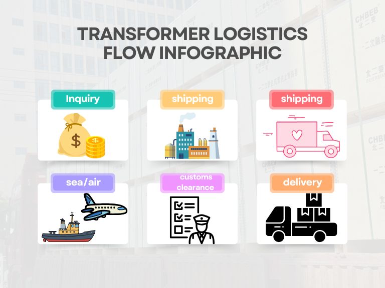
When logistics are unclear, budgets go through the roof. Delays get worse because of customs, port fees, and mistakes in packaging. This five-step method makes exporting transformers from China predictable by covering compliance, cost, modes, papers, and risk. This way, your project will arrive on time and on budget.
👉 Learn more: Oil-Immersed Transformer
Step 1: Compliance & Sourcing
Not doing compliance and supplier inspections might cause delays and fines. Set standards and capacities early on to keep your schedule and budget safe.
Supplier Vetting: Reliability, Certifications, and Manufacturing Hubs
- Certifications include IEC/IEEE1, ISO 9001/14001, and CE/KEMA. There are also type-test reports that show how the product works at different temperatures, with impulses, and with dielectrics.
- Experience with projects in the Middle East oil and gas, rural electrification in Africa, and cold-weather systems in Russia.
- China hubs:
- Shanghai/Ningbo → utilities and industrial units to the Middle East and Africa.
- Dalian/Yingkou → Russia and the CIS can get to the sea and train.
- Shenzhen/Guangzhou → strong routes to the West Coast of Africa.
- SGS/BV pre-shipment inspection; steel frame + moisture barrier + tilt/shock indicators; inspection and packing.
Learn about China’s rules and technical standards for exports.
- HS Code: 8504.33 or 8504.34 (ultimate subheading depends on the power rating).
- The main documents are the commercial invoice, packing list, bill of lading/AWB/rail consignment, certificate of origin, and oil MSDS.
- Regional compliance:
- SABER (KSA) and ESMA (UAE) are in the Middle East.
- Russia: EAC mark; Russian nameplate and papers.
- SONCAP in Nigeria, PVOC in Kenya, and NRCS in South Africa.
- IEC 60296 (mineral), IEC 61099 (synthetic ester), and IEC 62770 (natural ester) are the standards for insulating oil.
Step 2: Logistics & Cost
If you only look at ocean pricing, you miss origin/destination charges. To avoid surprises, break down costs into origin, main leg, destination, and inland.
Mode Comparison: Sea vs Air vs Special Cargo (Flat Rack / Rail)
| Mode | Pros | Limits | Best Use |
|---|---|---|---|
| Sea FCL | Lowest $/ton, minimal handling | Longer lead times | Bulk shipments to Middle East/Africa |
| Sea LCL | Flexible for small volumes | More touch points | Spares/small kits only |
| Flat Rack/Open Top | Handles OOG/oversize | Higher fees, port limits | 10–20 MVA oil-immersed main units |
| Air Freight | 3–7 days | High cost/weight limits | Urgent data center/utility spares |
| China–Russia Rail | Reliable to CIS/Russia | Border trans-loading | Russian grid/substation projects |
👉 Learn more: Dry vs Oil Transformer
Cost & Transit: Middle East, Russia, Africa (2025 reference)
FOB China, typical ranges; don’t include destination fees, tariffs, or taxes.
| Region | Port/Route | 20’ FCL Freight (USD) | Main Transit | Door-to-Door Typical |
|---|---|---|---|---|
| Middle East (Dubai/Jebel Ali) | Sea | 1,200–1,800 | 15–22 d | 25–35 d |
| Russia (St. Petersburg / Vladivostok) | Rail+Sea | 2,000–3,500 | 18–28 d | 30–40 d |
| Africa (Nigeria/Lagos) | Sea | 2,800–4,200 | 35–45 d | 45–60 d |
👉 Unit price signal: The price of a typical oil-immersed distribution transformer in 2025 will be between USD 20 and 60 per kVA, FOB China. Ester-oil units are normally 10% to 20% more for safety and the environment.
Important documents: HS Code, Commercial Invoice, and Bill of Lading
- Commercial Invoice: make sure the Packing List and B/L match in terms of specs, HS Code, Incoterms, and currency.
- List of things to pack: size, net/gross weight, and number of packages.
- Transport documents include a B/L (telex release or originals), an AWB, and a rail waybill.
- Tech files: datasheet, type-test, and oil compliance statement (IEC 60296/61099/62770). SONCAP is needed on some African roads.
Step 3: Risk Mitigation & Delivery
Not controlling risk can lead to demurrage, claims, or rework. Make sure that packaging, paperwork, and insurance are all the same to lower the risk of delivery.
Example: Transformer Export Packing & Delivery
Below is a real case video of how CHBEB prepares transformer packaging for export, including wooden crating, steel frame reinforcement, and moisture-proof sealing.
Common Issues & Solutions: Avoid Delays & Damage
| Issue | Solution |
|---|---|
| Port congestion/rollovers | Book early, avoid peak Q3/Q4, flexible routing |
| Damage/leaks | Steel frame + anti-rust + bracing; request loading photos/videos |
| High duties | Verify HS Code2 & FTA eligibility; pre-quote taxes |
| Doc mismatch | Pre-audit the “triple match” (Invoice/PL/B/L) |
| Inland access limits | Route survey for mines/desert/coastal sites; permits & cranes |
| Under-insurance | Buy ICC(A) cargo insurance for ≥110% invoice value |
Customs at the destination: duties, VAT, and procedures
- Middle East: KSA SABER and UAE ESMA; make sure that labels and markings are correct.
- Russia: EAC and Russian documents; rail trans-shipment at the border is routine.
- SONCAP (NG), PVOC (KE), and NRCS (ZA) are in Africa. Give them more time to clear.
(Add-On) Maintenance & Lifecycle
Step one is shipping. Long-term reliability protects ROI.
- Testing transformer oil for acid value, moisture, breakdown voltage, and DGA (dissolved gas analysis).
- Utilities once a year; data centers and mines every 6 to 12 months.
- The cost of replacing transformer oil adds to OPEX but stops catastrophic failures.
- Oil-immersed lasts 25 to 35 years, whereas dry-type lasts 20 to 25 years (with adequate care).
- Cleaning the enclosure: to keep the cooling system working and to stop corrosion, clean the tank and radiators on a regular basis in desert, coastal, and mining areas.
- Environmental and fire safety: spill containment, absorbents, foam/water-mist systems; make sure they follow IEC and local codes.
👉 Learn more: Transformer Maintenance Checklist
CHBEB — Reliable Partner for Distribution Transformers
With over 60 years of transformer manufacturing expertise, CHBEB has become one of China’s most trusted distribution transformer suppliers. The company operates two factories in Wenzhou, one in Nanjing, and an office in Beijing, ensuring both strong production capacity and responsive customer support.
What makes CHBEB stand out:
- Strict Quality Commitment: All raw materials are 100% new and high-grade — no recycled or downgraded components.
- Proven Reliability: A qualified supplier for the State Grid Corporation of China, with a spotless record of zero major accidents.
- 100% Product Testing: Every unit is fully tested before delivery to guarantee safety, efficiency, and long service life.
- Fast-Track Orders: Ability to fulfill urgent orders in as little as one week, helping customers meet tight project deadlines.
- Custom Inventory Planning: Flexible stocking and supply strategies designed to align with customer procurement schedules.
- Global Outlook: Rooted in China and expanding worldwide, CHBEB actively supports local agents and partners, including assistance with market-specific certifications.
- Flexible Customization: Tailored transformer designs for utilities, contractors, and industrial clients, with reliable quality and fast delivery.
👉 Looking for a distribution transformer manufacturer that combines Chinese manufacturing strength with international standards?Contact CHBEB for a tailored solution or Download our full transformer catalog here.
FAQs
⏱ How long does shipping from China take?
Middle East: 3–5 weeks sea. Africa: 6–8 weeks sea. Russia: 3–5 weeks rail+sea. Air: 3–7 days for urgent parts.
🚢 What’s the best shipping method?
Sea FCL for heavy units; Flat Rack/Open Top for oversize oil-immersed; Air for urgent spares; Rail for Russia/CIS.
💰 Do I owe duties/VAT?
Yes. Duty & VAT depend on HS 8504 subheading and destination rules; use a licensed customs broker.
📦 Can I track the shipment?
Yes—via B/L, AWB, or rail waybill tracking provided by your forwarder.
📍 Any packaging must-haves?
Steel frame + wooden crating, anti-rust treatment, vibration/tilt indicators, marked C.G. and lifting points.
Conclusion
To deliver transformers on time and within budget, buyers should follow five clear steps: compliance checks, logistics planning, cost deconstruction, risk mitigation, and customs clearance. But success doesn’t stop at planning—choosing the right partner matters.
With CHBEB’s export experience, strict packaging standards, and familiarity with certifications like SABER, EAC, SONCAP, projects in the Middle East, Africa, and Russia avoid the most common traps: hidden port fees, customs delays, and repacking errors. By shipping directly from our factories, clients save weeks of coordination and minimize unexpected costs.
👉 Contact CHBEB today for compliant, cost-stable, and export-ready transformer shipping solutions tailored to your region.
