Why do transformers get immersed in oil?
Introduction
Transformers can get too hot, break down, and cost a lot of money to fix if they don’t have oil. People often ask why transformers “sit in oil.” The answer is that transformer oil is important because it keeps systems cool, stops arcs, and makes sure that power projects around the world work safely and well for a long time.
What Is an Oil-Immersed Transformer?
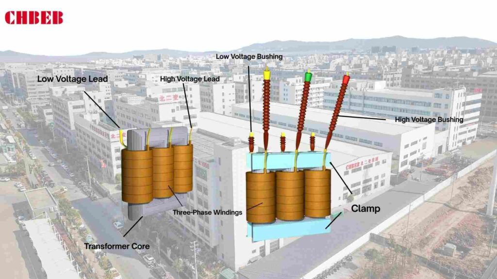
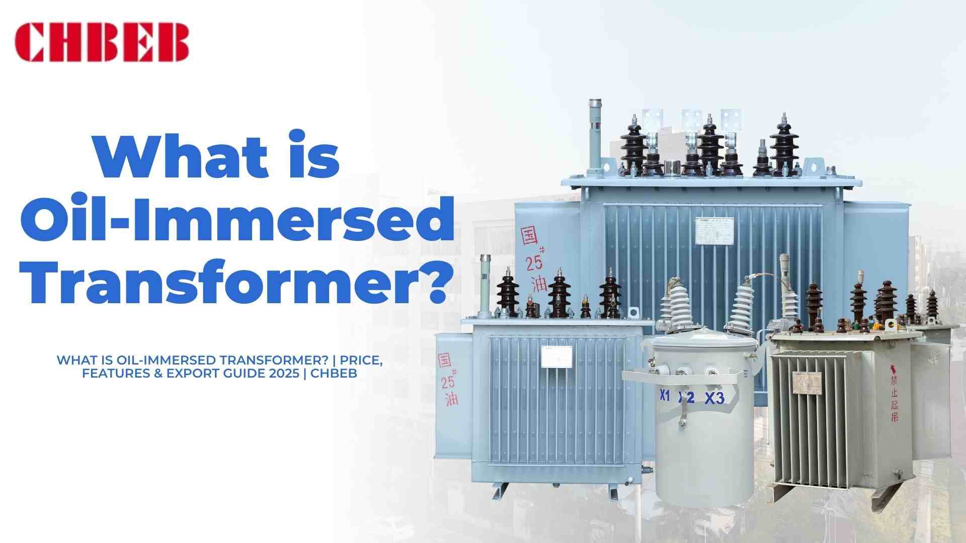
A lot of buyers don’t know what “oil-immersed” means. Without this information, it’s hard to choose the right transformer. An oil-immersed transformer is a power transformer that has insulating oil all over its core and windings.
- Function: Changes the voltage levels in grids and systems used in industry
- Structure: An iron core with primary and secondary coils inside oil
- Oil’s job is to keep things cool and insulated, which keeps them safe for a long time.
- The capacity ranges from a few kVA to hundreds of MVA.
- Uses: networks for transmission, factories, substations, building sites, mining operations, data centers, and networks for distributing goods in cities
👉 To put it simply, oil immersion makes transformers with a lot of power safe, reliable, and long-lasting.
The Oil’s Dual Mission: The Science Behind Its Essential Functions
Transformers would get too hot or break down without oil. Oil does both cooling and insulating, which are two important things for safe functioning.
Mission 1: Super-Efficient Cooling (The Transformer’s “Coolant System”)
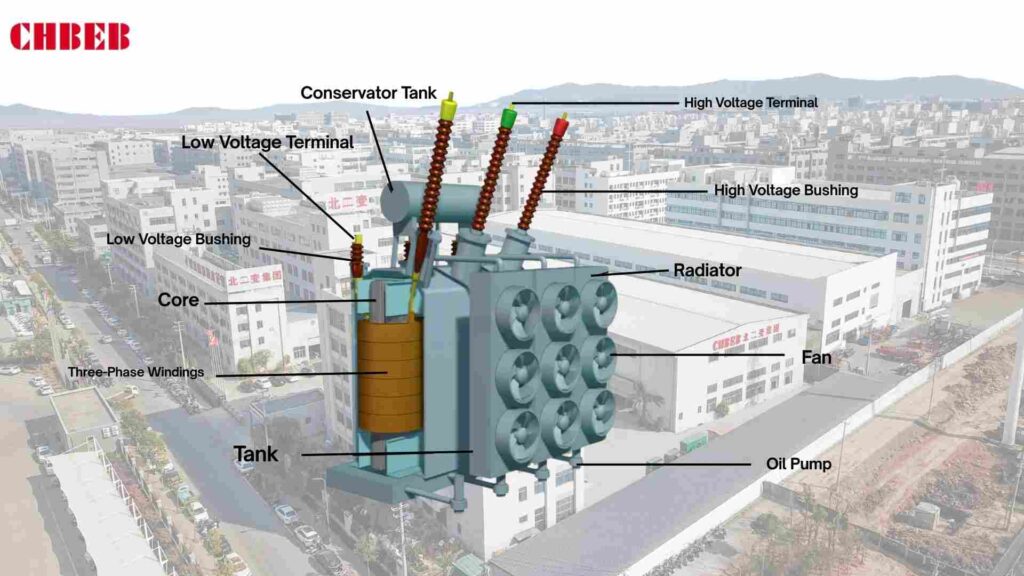
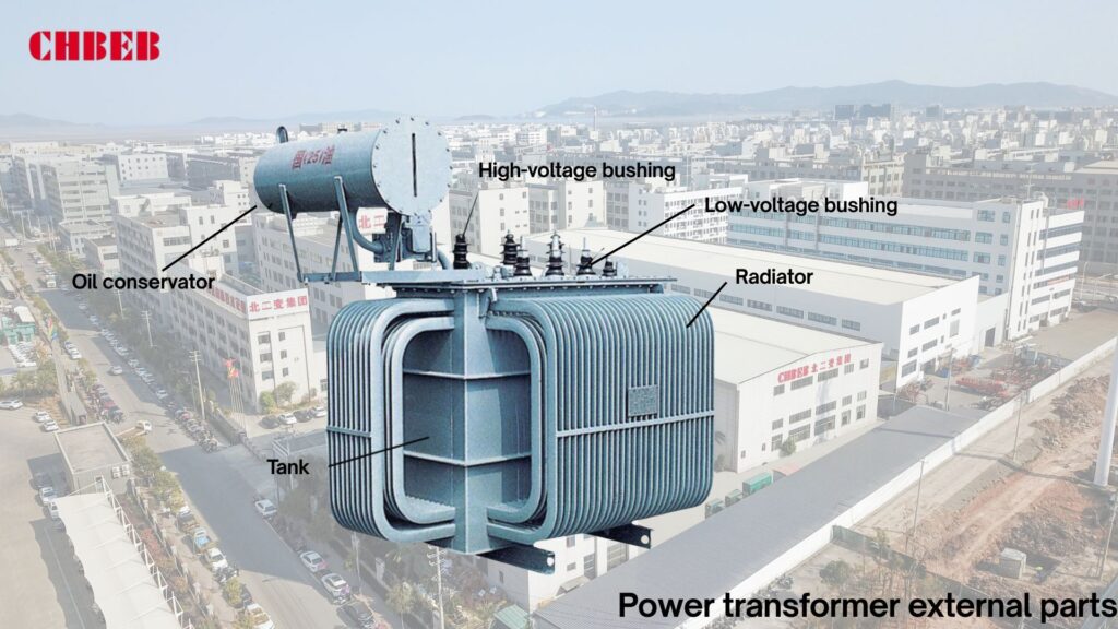
Too much heat can harm insulation and limit its life. This heat is absorbed by the transformer oil and sent to the radiator fins and tank walls, where it can be released.
👉Like radiator fluid in a car, transformer oil keeps the temperature stable and makes the equipment last longer.
Mission 2: Electrical insulation, which is the “safety barrier” against short circuits
Arcing and incomplete discharge put safety inside at risk. Oil surrounds the windings and core, making a dielectric shield.
👉The insulating oil has a very high dielectric strength1, which stops arcs and discharges from happening and keeps the transformer running safely and steadily even when the voltage is high.
Practical Trade-Offs: Oil vs. Air
Some people question, “Why oil when there are dry-type transformers?” If you don’t have a clear comparison, you can make the wrong choice for your project.
| Factor | Oil-Immersed Transformer | Dry-Type Transformer |
|---|---|---|
| Cooling | High efficiency, supports heavy loads | Limited by air flow |
| Insulation | Oil dielectric ~15 kV/mm | Relies on solid resin |
| Size & Cost | Compact, USD 20–60/kVA FOB China (2025 typical price) | Bulkier, higher unit cost |
| Applications | Power plants, factories, mines, data centers, city distribution | Buildings, tunnels, metro |
| Lifespan | 25–35 years (with proper maintenance) | 20–25 years |
👉 The price of a typical oil-immersed transformer unit in 2025 will be between USD 20 and 60 per kVA FOB China, depending on the voltage and capacity.
– Mineral oil units: cheaper to buy up front and used a lot in Africa.
– Synthetic/Natural ester oil units are 10–20% more expensive, but they are fire-resistant and good for the environment, hence they are popular in Europe and in cities.
Safety and the Future: Types of Transformer Oil and Green Trends
People are becoming more worried about the risk of fire and the effect on the environment. Buyers are hesitant without standards and safe oils. New oils and rules around the world offer answers.
- Mineral Oil (IEC 60296): cheap, common, but flammable and bad for the environment
- Synthetic Ester Oil (IEC 61099): Doesn’t break down easily, doesn’t catch fire, and is great for metropolitan areas.
- Natural Ester Oil (IEC 62770): Made from plants, renewable, and good for the environment for green projects
Regional insights:
– Mineral oil units are the most common in Africa since they are cheap.
– Eco-regulations say that ester oils are better for urban substations in Europe.
– Utilities in the Middle East use mineral oil for grids and ester oil for oil and gas projects.
👉 The future is clear: eco-friendly ester oils are taking the place of mineral oils more and more, notably in cities and renewable energy projects.
Maintenance & Risk Reminders: Extending Transformer Lifespan
Not doing maintenance on transformers shortens their life and costs more. You need to check oil often and take steps to keep it from breaking down.
- You should regularly test transformer oil for its acid value, moisture content, breakdown voltage, and DGA (Dissolved Gas Analysis)2.
- Testing cycle: Utilities test once a year, whereas data centers and other critical sites test every 6 to 12 months.
- Replacement cost: Oil changes and treatments add to OPEX, but they stop failures that cost a lot more.
- Enclosure cleaning: The external tank and cooling fins of oil-immersed transformers should be cleaned regularly to remove dust, oil stains, and salt deposits. This improves cooling efficiency and prevents corrosion, especially in coastal or industrial environments.
- Life expectancy: Units that are immersed in oil usually last 25–35 years, while dry-type units last 20–25 years.
- Risks: Oil spills can damage soil and water; fire safety systems must be in place according to IEC and local requirements.
👉 Taking care of transformer oil properly not only makes it last longer, but it also decreases the total cost of ownership.
CHBEB — Reliable Partner for Distribution Transformers
With over 60 years of transformer manufacturing expertise, CHBEB has become one of China’s most trusted distribution transformer suppliers. The company operates two factories in Wenzhou, one in Nanjing, and an office in Beijing, ensuring both strong production capacity and responsive customer support.
What makes CHBEB stand out:
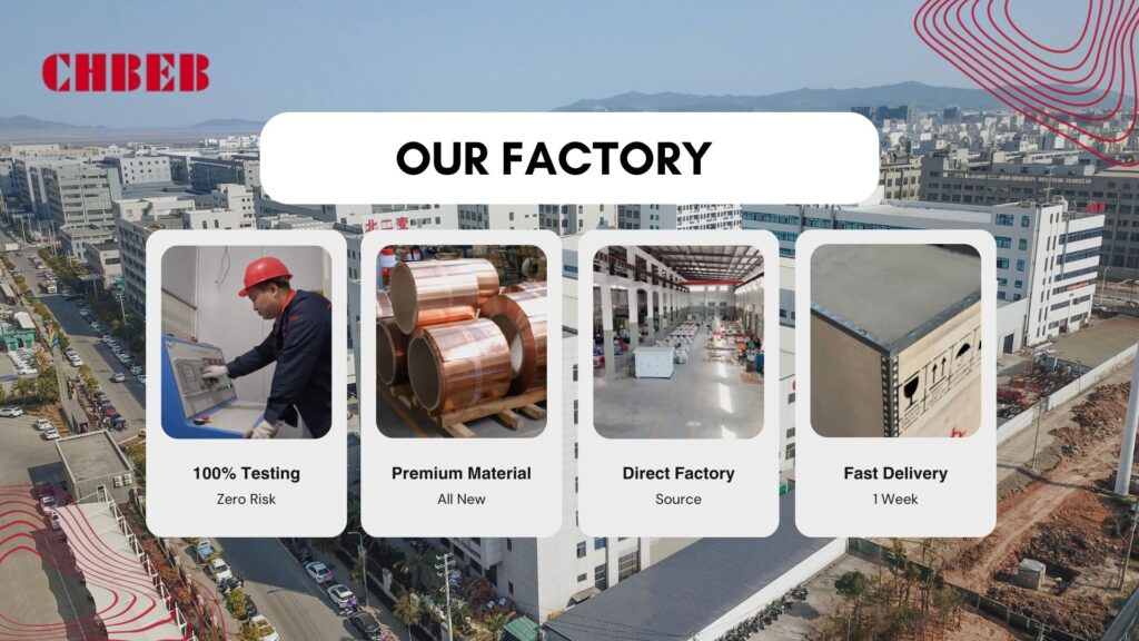
- Strict Quality Commitment: All raw materials are 100% new and high-grade — no recycled or downgraded components.
- Proven Reliability: A qualified supplier for the State Grid Corporation of China, with a spotless record of zero major accidents.
- 100% Product Testing: Every unit is fully tested before delivery to guarantee safety, efficiency, and long service life.
- Fast-Track Orders: Ability to fulfill urgent orders in as little as one week, helping customers meet tight project deadlines.
- Custom Inventory Planning: Flexible stocking and supply strategies designed to align with customer procurement schedules.
- Global Outlook: Rooted in China and expanding worldwide, CHBEB actively supports local agents and partners, including assistance with market-specific certifications.
- Flexible Customization: Tailored transformer designs for utilities, contractors, and industrial clients, with reliable quality and fast delivery.
👉 Looking for a distribution transformer manufacturer that combines Chinese manufacturing strength with international standards?Contact CHBEB for a tailored solution or Download our full transformer catalog here.
Conclusion
Transformer oil is not just a liquid filler—it is the core element that determines cooling, insulation, cost, and service life of an oil-immersed transformer. Choosing the right oil type (mineral, synthetic ester, or natural ester) directly affects fire safety, environmental compliance, and OPEX. Regular oil testing—such as DGA tests, breakdown voltage checks, and moisture analysis—helps extend lifespan from 25–35 years and prevents costly failures.
Key Takeaways for Global Buyers
- Price: 2025 FOB China ranges USD 20–60/kVA, with ester oils costing 10–20% more.
- Safety: Ester oils are increasingly replacing mineral oil in cities and green projects.
- Maintenance: Proper oil monitoring reduces total cost of ownership.
From African mining sites to European substations and Middle Eastern grids, oil-immersed transformers remain the backbone of reliable power distribution.
📞 Contact CHBEB for 2025 oil-immersed transformer price lists, oil-type comparisons, and export-ready solutions tailored for your project in Southeast Asia, Africa, or the Middle East.
How do I calculate the shipping cost of a transformer from China to my country?
Introduction
Freight mistakes inflate budgets and delays. Unclear charges, wrong mode, and customs traps frustrate buyers. This five-step process calculates transformer international shipping cost, improves transformer logistics, and delivers a reliable door-to-door budget from China to your country.
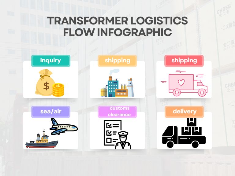
Cost Deconstruction: The Three Phases of International Freight
PAS lead-in: The ocean rates aren’t the only thing you have to pay. If you don’t pay attention to origin and destination costs, you can get surprise bills. To avoid budget surprises, break down costs into origin, major carrier, and destination.
Step 1: China Local Charges and Export Paperwork (EXW to FOB)
If you don’t do your origin responsibilities, you’ll miss trucks and have to pay demurrage. List everything from the manufacturing gate to the ship loading so that you can give over the goods cleanly.
- Pickup and transportation from the factory (EXW)
- THC and port fees in China
- Customs declaration for export
- Commercial invoice, packing list, bill of lading, and telex release are all documents.
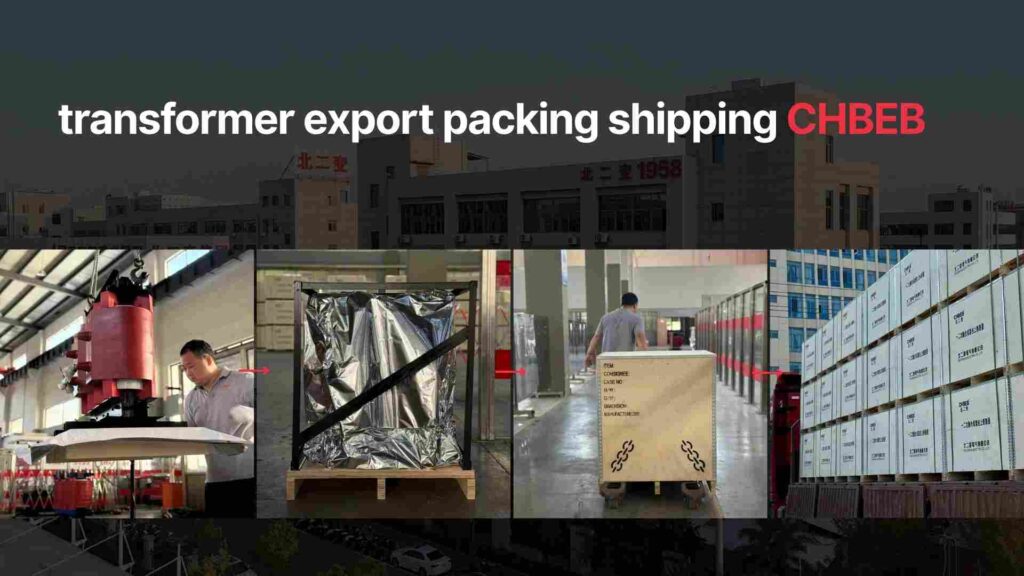
- Lashing and crating hefty transformers
- Moisture- and rust-proof packing; a forwarder agency and booking; and optional CoO/FTA forms
| Item | Est. Cost (USD) | Note |
|---|---|---|
| Trucking to port | 180–320 | Distance & weight |
| THC & port fees | 120–180 | Terminal/wharf |
| Export customs & docs | 60–120 | Broker + EDI |
| Lashing/steel frame | 150–400 | By weight/dimensions |
| Telex release (optional) | 30–50 | No original B/L courier |
Note: You also have to pay for pickup and export clearance under EXW. The supplier takes care of export and loading on the vessel under FOB.
Phase 2: Costs of international shipping and chargeable weight1 (FCL vs. LCL2)
Getting FCL and LCL wrong makes the cost of transporting transformers internationally to up. To make transformer logistics as efficient as possible, you need know what metrics you can charge for and when you will break even.
- CBM (m³) = L × W × H × the number of packages
- LCL billing = W/M (1 CBM is about 1 metric ton)
- The maximum of gross kg and CBM × 167 is the air bill.
| Mode | Pros | Cons | Best Use |
|---|---|---|---|
| LCL | Flexible for small volume | More handling, longer dwell | ≤10–12 CBM |
| FCL 20’ | Fewer touches, safer | Pay whole box | ≥12–28 CBM or heavy |
| FCL 40’ | Best $/CBM at scale | Higher base rate | ≥28 CBM |
| OOG/Breakbulk | Fits oversize units | Complex permits/fees | Oversize transformers |
| Air | Fastest | Very expensive | Urgent small spares |
For example, in Africa, a rural electrification initiative commonly combines multiple tiny transformers into one FCL to minimize the cost per unit. A site in the Middle East for oil and gas may need OOG breakbulk since single units are too big for containers.
Price signal: In 2025, the average cost of shipping a transformer internationally will be between USD 3,000 and 6,000 for a 20′ FCL FOB China, without including customs and delivery within the country.
Phase 3: Fees for the destination port, customs clearance, and delivery within the country
Ignoring destination fees leads to arguments and extra charges for storage. Plan your local budgets and timetables ahead of time to keep projects on track.
- Destination THC, ISPS3, and terminal admin
- Entry filing and customs broker; duties and taxes (based on HS 8504)
- Checks: fumigation, x-ray, and physical
- Demurrage or detention after free time
- Heavy-haul inland: permits, escorts, cranes, route survey, and lift plan
Critical Decisions: Choosing the Right Incoterms and Shipping Mode
PAS lead-in: Unclear duties lead to blaming others. Set Incoterms and mode early, write down who pays what, and make sure everything matches your site and timeframe.
What FOB, CIF, and EXW mean for your costs and risks in trade
Choose the phrase that fits your level of control and skill. Weigh the pros and cons of each.
| Task/Cost | EXW | FOB | CIF |
|---|---|---|---|
| Factory pickup | Buyer | Buyer | Seller |
| Export clearance | Buyer | Seller | Seller |
| Main carriage | Buyer | Buyer | Seller |
| Insurance (minimum) | Buyer | Buyer | Seller |
| Destination & inland | Buyer | Buyer | Buyer |
FOB means you have balanced control with your forwarder. CIF means a price that can be predicted at the port; check destination fees ahead of time.
Logistics Mode: Why You Should Choose Sea Freight, Air Freight, or Multimodal
The wrong mode will cost you money, so make sure the specs and deadlines match the proper lane.
- Sea (FCL/LCL/OOG): best price per ton; takes 3 to 6 weeks on average.
- Air: 2 to 7 days; use for small, urgent HV parts.
- Rail/Multimodal: helpful for Central Asia and Europe.
- Breakbulk/RO-RO: units that are too heavy or too big.
A data center in Southeast Asia might send auxiliary equipment by air freight and major transformers by sea to keep costs down while synchronizing installation.
Risk Mitigation: Avoiding Hidden Costs and Customs Traps
PAS lead-in: Just because the headline rates are low doesn’t mean the landed costs would be low. Mistakes at customs and in storage might eat up profits. Include protections in quotes and contracts.
Duties and Taxes: Using the HS Code to Figure Out Rates
Fines and delays happen when HS codes are entered incorrectly. Most of the time, transformers fall under HS 8504, which is broken down by rating and kind. Calculate the right customs value (usually CIF), then add VAT/GST and other fees. Nameplate, drawings, CoO/FTA, and test reports should all be in a file.
Your Transformer Freight Inquiry Checklist is a useful tool.
Full info is needed for accurate quotes. Share these facts to lower the cost of shipping your transformer internationally and make the logistics of moving it easier.
- Cargo and packaging: kind, kVA/kV, size, gross weight, crate or skid, and whether the oil has been drained?
- Origin and timing: pickup address, China port, ETD/ETA window
- Mode and Incoterm: EXW, FOB, CIF, FCL, LCL, OOG, and air
- Destination: port, broker, site access, and crane plan
- Documents: an invoice, a packing list, an HS code, a CoO/FTA, and test reports
- Format for quotes: divide between origin, main, and destination; free time; and list of surcharges
| Phase | Cost Basis | Est. Cost (USD) | Notes |
|---|---|---|---|
| Origin (FOB) | Fixed | 450 | Lashing + docs |
| Ocean (20’ FCL) | Box rate | 1,250 | Lane/season |
| Insurance | % cargo value | 180 | ICC(A) |
| Destination | Local tariffs | 520 | Handling & admin |
| Customs & broker | Fixed + % | 200 | Excl. duty/VAT |
| Inland | Permits + crane | 480 | ~200 km haul |
| Subtotal (excl. duty/VAT) | 3,080 | Illustrative 2025 |
CHBEB — Reliable Partner for Distribution Transformers
With over 60 years of transformer manufacturing expertise, CHBEB has become one of China’s most trusted distribution transformer suppliers. The company operates two factories in Wenzhou, one in Nanjing, and an office in Beijing, ensuring both strong production capacity and responsive customer support.
What makes CHBEB stand out:
- Strict Quality Commitment: All raw materials are 100% new and high-grade — no recycled or downgraded components.
- Proven Reliability: A qualified supplier for the State Grid Corporation of China, with a spotless record of zero major accidents.
- 100% Product Testing: Every unit is fully tested before delivery to guarantee safety, efficiency, and long service life.
- Fast-Track Orders: Ability to fulfill urgent orders in as little as one week, helping customers meet tight project deadlines.
- Custom Inventory Planning: Flexible stocking and supply strategies designed to align with customer procurement schedules.
- Global Outlook: Rooted in China and expanding worldwide, CHBEB actively supports local agents and partners, including assistance with market-specific certifications.
- Flexible Customization: Tailored transformer designs for utilities, contractors, and industrial clients, with reliable quality and fast delivery.
👉 Looking for a distribution transformer manufacturer that combines Chinese manufacturing strength with international standards?Contact CHBEB for a tailored solution or Download our full transformer catalog here.
Conclusion
Calculating the shipping cost of a transformer from China requires breaking it down into three phases: origin charges, main carriage, and destination handling. By defining Incoterms clearly, choosing the right shipping mode, and preparing documents such as HS 8504 codes, certificates of origin, and packing lists, buyers can avoid hidden costs, customs penalties, and demurrage.
Beyond calculation, the real challenge lies in execution. Poor lashing, incomplete paperwork, or misquoted chargeable weight can easily turn a low freight rate into unexpected expenses. This is why working with an experienced transformer manufacturer matters. At CHBEB, every transformer is delivered with export-ready wooden crating, moisture protection, and steel frame lashing, reducing inspection risks and saving buyers time at customs. We also coordinate seamlessly with forwarders, provide complete commercial invoices, and ensure compliance with IEC/UL standards—so clients don’t need to worry about repacking, missing documents, or last-minute delays.
With disciplined cost planning and a reliable supplier, transformer logistics becomes predictable. Buyers not only secure competitive freight rates but also gain peace of mind knowing their projects will be delivered on time, on budget, and fully compliant.
Introduction
It’s hard to know which transformer to choose. If you choose the wrong one, you risk safety, downtime, and higher costs. Dry-type transformers1 fix this by using safer insulation and being easier to maintain. They are perfect for projects in Southeast Asia, Africa, the Middle East, Russia, and Belt & Road countries.
What is a Dry Transformer?
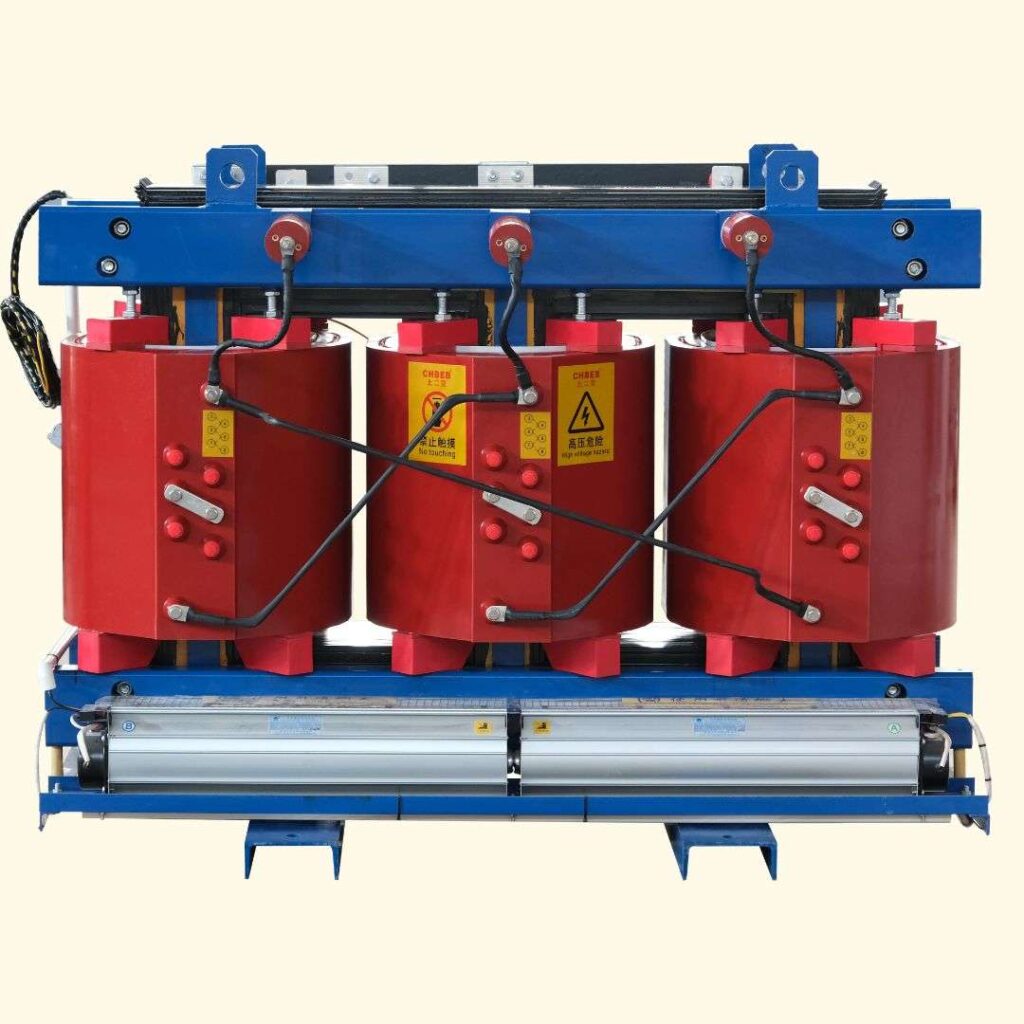
A dry-type transformer is an electrical transformer that uses air or gas as the insulating medium instead of liquid. Unlike oil-immersed transformers, it does not rely on insulating oil for cooling or insulation.
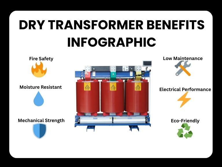
Dry transformers offer several advantages:
- Safety & Reliability – With no liquid to leak or ignite, they significantly reduce fire and environmental risks.
- Low Maintenance – Since there is no oil, there is no need for periodic oil testing, replacement, or leak checks, lowering long-term maintenance costs.
- Compact & Lightweight – For the same power rating, dry-type transformers are usually smaller and lighter because they use efficient coil designs that save space.
- Durability – Their robust insulation structure makes them suitable for indoor use and harsh environments without risk of oil degradation.
These benefits make dry-type transformers a preferred choice in applications such as commercial buildings, hospitals, data centers, and other locations where safety and reliability are critical.
👉 Read more: The Ultimate Guide to Cast Resin Dry Type Transformers
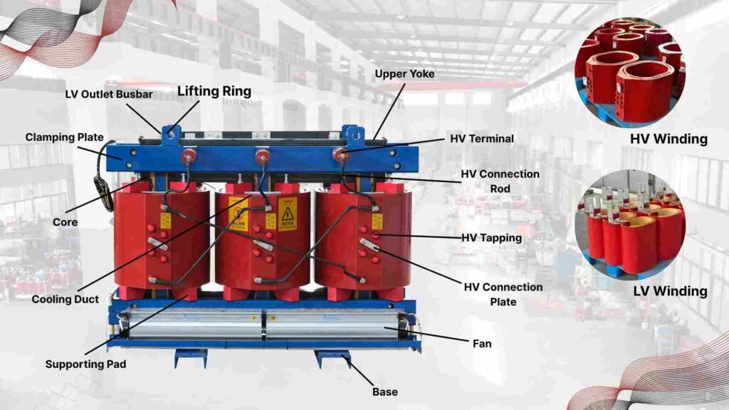
What is a Three-Phase Dry-Type Transformer?
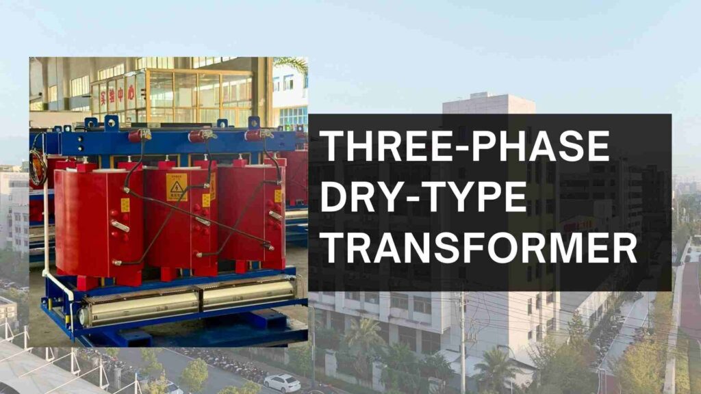
A three-phase dry-type transformer is a self-cooled transformer designed with two windings and available in a wide range of primary and secondary voltage combinations. It is widely used in industrial and commercial applications where large power capacity is required.
Operating on a three-phase power supply, the transformer is built with three sets of windings on both the primary and secondary sides. This design ensures efficient power distribution, reduced conductor material requirements, and stable performance under heavy loads.
What is the Use of a Dry Transformer?
Dry-type transformers are static electrical devices that rely on air circulation and high-temperature insulation materials (such as DuPont Nomex) for cooling. During voltage conversion, heat generated in the windings is effectively dissipated through this air-insulation system, ensuring safe and reliable operation.
These transformers are commonly installed in indoor environments where exposure to water or liquid is minimal. Thanks to their non-flammable insulation system, they are also the preferred choice in fire-sensitive locations such as chemical plants, oil refineries, and high-occupancy buildings.
Dry Type Transformer Standards
Unclear standards create hidden risks. Certified ratings ensure efficiency and compliance. Typical 1.2 kV class benchmarks:
Single-Phase:
- 15 kVA at 97.70
- 50 kVA at 98.30
- 100 kVA at 98.60
- 250 kVA at 98.80
Three-Phase:
- 30 kVA at 98.23
- 112.5 kVA at 98.70
- 300 kVA at 99.02
- 1000 kVA at 99.28
📌 For buyers: higher efficiency = lower long-term energy costs, critical for African utilities and Southeast Asian commercial centers.
👉 Read more: How To Purchase A 1000kVA Transformer
What is a Dry Type Distribution Transformer?
A dry-type distribution transformer is the final stage of an electrical distribution system, stepping down voltage from the secondary side of the main power transformer to the level required by end-user loads.
Unlike oil-filled transformers, it uses air or gas insulation instead of liquid. In some designs, the unit is pressurized with nitrogen gas, which helps prevent moisture absorption, mold growth, and insulation degradation.
Dry-type distribution transformers are suitable for both indoor and outdoor installations. They can be placed in vaults, mounted on poles, or installed underground, providing protection against weather conditions and unauthorized access.
👉 Read more: Oil-Immersed Distribution Transformers Guide
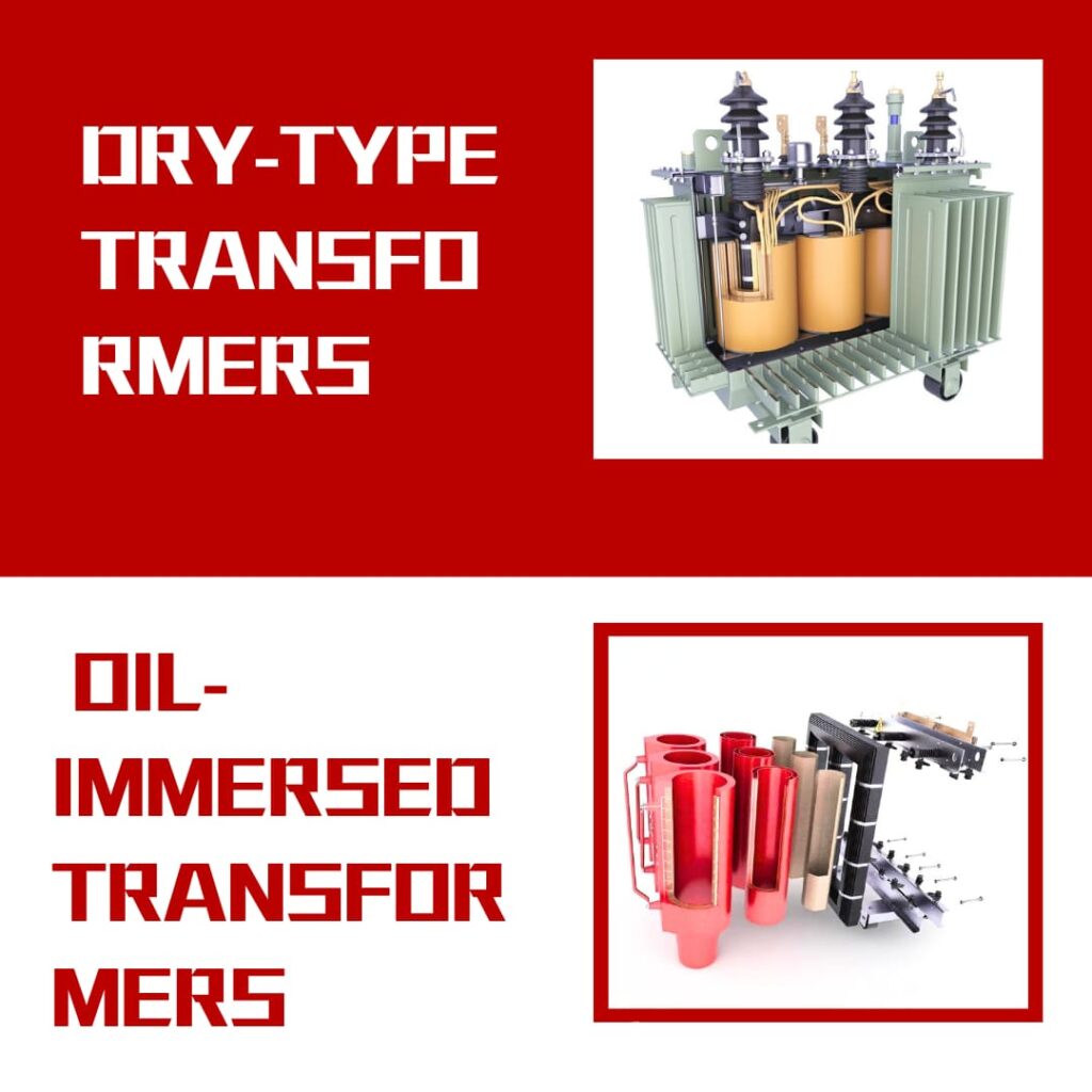
Dry Type VS Oil Type Transformers
| Feature | Dry-Type Transformer | Oil-Immersed Transformer |
|---|---|---|
| Cooling | Air / Epoxy Resin | Mineral Oil |
| Fire Safety | Excellent (no oil) | Risk of oil fire |
| Maintenance | Low | Higher (oil testing, replacement) |
| Capacity | 50–3150 kVA | 50–25,000 kVA |
| Service Life | 20–25 years | 25–30 years |
| Price (2025) | USD 40–90/kVA | USD 20–50/kVA |
Price Comparison: Dry vs Oil Transformers (2025)
| Capacity (kVA) | Dry-Type (USD/kVA) | Oil-Type (USD/kVA) | Example FOB China Price (USD) | Typical Application |
|---|---|---|---|---|
| 500 | 70–85 | 55–65 | Dry: 35,000–42,500 · Oil: 27,500–32,500 | Commercial, small factories |
| 1000 | 65–80 | 45–60 | Dry: 65,000–80,000 · Oil: 45,000–60,000 | Hospitals, industrial parks |
| 2000 | 60–75 | 40–55 | Dry: 120,000–150,000 · Oil: 80,000–110,000 | Data centers, substations |
Prices vary by copper/aluminum windings, loss levels (0.6 vs 1.1), and IEC/UL certification.
What are the Advantages of a Dry Transformer?
- Key Advantages of Dry-Type Transformers
- 1. Better Overload Capacity
- Dry-type transformers can handle overloads more effectively than oil-filled transformers. Their windings are naturally cooled by surrounding air, reducing the risk of overheating during peak loads.
- 2. Low Partial Discharge2
- Partial discharge is a common cause of insulation failure in transformers, typically occurring in tiny voids within the insulation. Dry-type transformers minimize this risk because their windings are embedded in solid insulation material, free from air gaps or voids.
- 3. Outdoor Installation Ready
- Thanks to their oil-free design, dry transformers eliminate the risk of leakage. They can be safely installed outdoors within IP45-rated enclosures, ensuring reliable operation in diverse environments.
- 4. Zero Fire Hazard
- With non-flammable air or resin insulation, dry-type transformers pose virtually no fire risk. This makes them safer than oil-immersed transformers, where flammable insulating oil increases fire hazards.
- 5. Non-Hygroscopic Design
- Dry-type transformers do not absorb moisture from the atmosphere. This resistance to humidity and corrosion makes them highly reliable for outdoor and high-moisture environments.
Can Dry Transformers Be Used Outside?
Yes—if properly enclosed. Use IP-23, IP-45, or IP-54 protection to resist dust, humidity, and water jets.
How Are Dry Transformers Cooled?
- Self-cooling (AN): Air circulation, typical for schools/offices
- Forced cooling (AF): Fans or blowers, needed in data centers and heavy industry
How Do You Protect a Dry Transformer?
- Electrical: Circuit breakers, surge arresters, grounding
- Thermal: Sensors, relays, cooling fans
- Enclosure: IP-rated shells (IP20 for indoor, IP45/IP54 for outdoor, IP65 for harsh sites)
Typical Dry Transformer Prices (2025)
👉 Typical dry transformer prices in 2025: USD 40–90/kVA FOB China.
- Small units (50–500 kVA): USD 40–60/kVA
- Medium units (1000–2500 kVA): USD 60–90/kVA
- Example 1000 kVA (11/0.4 kV): USD 40,000–70,000
Buyers should compare transformer price quotes from different dry transformer suppliers in China to balance quality vs. cost.
CHBEB — Reliable Partner for Distribution Transformers
With over 60 years of transformer manufacturing expertise, CHBEB has become one of China’s most trusted distribution transformer suppliers. The company operates two factories in Wenzhou, one in Nanjing, and an office in Beijing, ensuring both strong production capacity and responsive customer support.
What makes CHBEB stand out:
- Strict Quality Commitment: All raw materials are 100% new and high-grade — no recycled or downgraded components.
- Proven Reliability: A qualified supplier for the State Grid Corporation of China, with a spotless record of zero major accidents.
- 100% Product Testing: Every unit is fully tested before delivery to guarantee safety, efficiency, and long service life.
- Fast-Track Orders: Ability to fulfill urgent orders in as little as one week, helping customers meet tight project deadlines.
- Custom Inventory Planning: Flexible stocking and supply strategies designed to align with customer procurement schedules.
- Global Outlook: Rooted in China and expanding worldwide, CHBEB actively supports local agents and partners, including assistance with market-specific certifications.
- Flexible Customization: Tailored transformer designs for utilities, contractors, and industrial clients, with reliable quality and fast delivery.
👉 Looking for a distribution transformer manufacturer that combines Chinese manufacturing strength with international standards?Contact CHBEB for a tailored solution or Download our full transformer catalog here.
👉 Secure your order early to avoid price increases and shipping delays in 2025.
How Long is Delivery Time in 2025?
- Small units (≤1000 kVA): 1–2 months
- Large units (≥2000 kVA): 2–5 months
- Bulk/custom orders: up to 12 months depending on supplier capacity
How to Choose a Reliable Dry Transformer Supplier in China?
- Check IEC/ISO certifications
- Verify project references in your region
- Request factory test reports before placing an order
- Compare 2–3 dry transformer suppliers China for fair price & quality assurance
Conclusion
In 2025, dry transformers remain the safer and more sustainable choice for critical projects. But the key is not only what you buy, but how you buy it.
✅ Practical steps for buyers:
- Define specs clearly – kVA, enclosure IP, loss class, winding material.
- Verify certifications – IEC/ISO compliance, PD and temperature-rise reports.
- Balance cost vs. lifecycle value – calculate long-term energy savings and service.
- Plan delivery early – standard 1–2 months, custom units up to 6 months.
By following this checklist, buyers can reduce procurement risks, secure reliable delivery, and ensure dry transformers operate safely for 20+ years.
Introduction
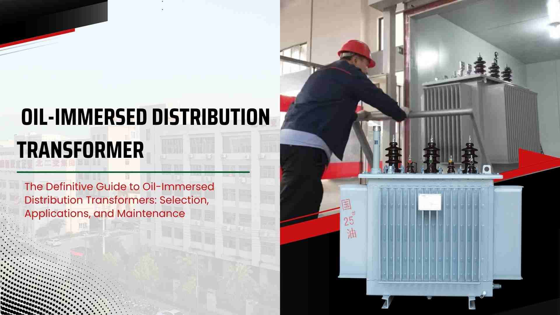
Many projects are plagued by power outages, expensive inefficiencies, and system dangers. Customers sometimes don’t know which transformer to trust, which wastes money and effort. The answer is clear: learn about oil-immersed distribution transformers1, including what they are, how to pick the right one, and how to keep it in good shape for years of reliable operation.
The Basics: What Is an Oil-Immersed Distribution Transformer?
Equipment faults and unstable electricity can stop operations. Many buildings have to deal with high energy expenses and safety problems. Oil-immersed distribution transformers are the answer. They make sure that power is delivered safely, efficiently, and consistently.
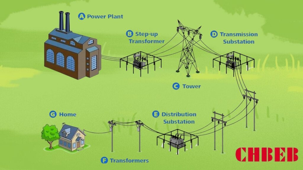
The “Last Mile” in Power Distribution: What It Means and How It Works
Power plants create electricity that is too strong to use directly. This causes problems for homes, businesses, and factories. Oil-immersed distribution transformers fix this by lowering the voltage to levels that may be used. They are the “last mile” in the grid’s distribution chain.
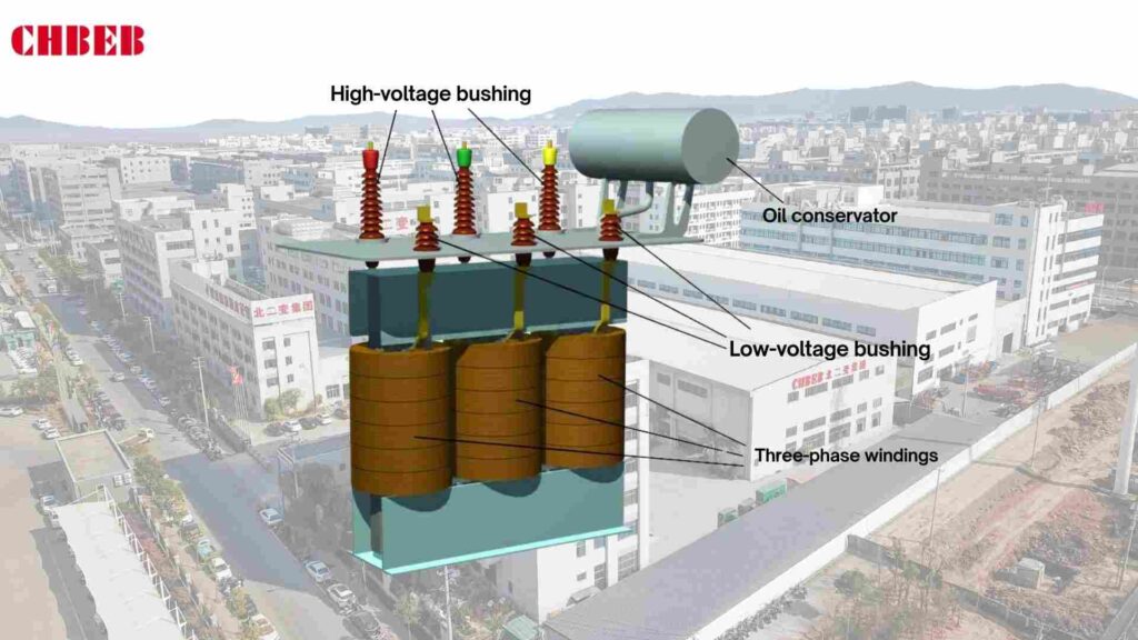
They have a magnetic core and windings that are completely covered in insulating oil. The oil not only keeps things cool, but it also absorbs and spreads heat, which makes sure that the machine works well even when it’s under a lot of stress.
The main difference between distribution transformers and power transformers is
Mistakes that cost a lot of money happen when people mix up power and distribution transformers. Knowing the difference makes sure you buy the right things.
- Power transformers are used in transmission networks to handle very high voltages (≥ 132 kV). Made to work best when fully loaded.
- Distribution transformers work at lower voltages (< 36 kV) and send power straight to end customers. Optimized for efficiency even when not fully loaded.
| Feature | Power Transformer | Distribution Transformer |
|---|---|---|
| Voltage Level | ≥ 132 kV | ≤ 36 kV |
| Operation | Transmission network | Distribution network (“last mile”) |
| Efficiency Focus | High load efficiency | All-day efficiency at variable load |
| Typical Installation | Power stations, substations | Residential, commercial, industrial |
The Selection Guide: Choosing the Right Transformer for Your Project
Choosing the wrong transformer can lead to overheating, losses, and breakdowns that happen a lot. This not only costs more, but it also makes things last less long. Before selecting a choice, you should look at the most important factors.
Important Factors: Capacity, Voltage, and Cooling Method
Not paying attention to specs can cause problems and cost a lot of money to fix. The best way to go about it is to concentrate on three main factors:
- Capacity (kVA rating): Make sure the capacity of the transformer is big enough to handle your current load and any expansion you expect in the future.
- Voltage (HV/LV levels) should match the needs of the grid supply and the end user.
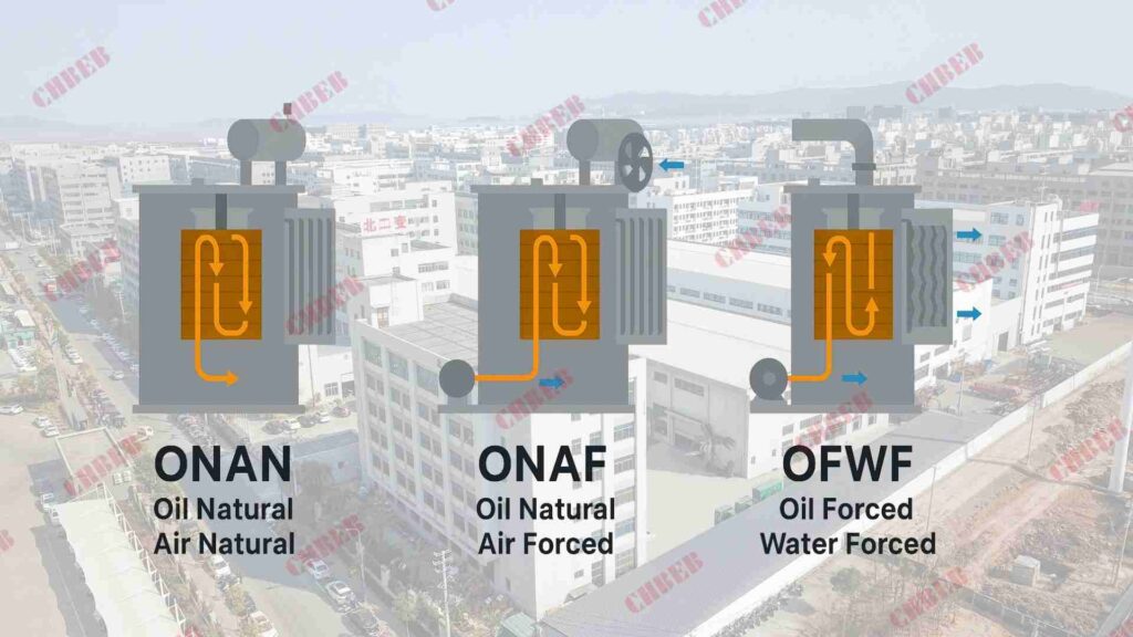
- Choose a cooling method (ONAN, ONAF, OFWF2, etc.) based on the load and environment in which it will be used.
| Cooling Method | Full Form | Typical Use Case |
|---|---|---|
| ONAN | Oil Natural Air Natural | Standard distribution transformers |
| ONAF | Oil Natural Air Forced | Industrial projects with higher load |
| OFWF | Oil Forced Water Forced | Large-scale, high-capacity projects |
Structural Comparison: Conservator Tank vs. Hermetically Sealed
People often can’t decide between hermetically sealed and conservator types. Depending on the needs of the project, each structure has its own advantages.
- Transformers that are sealed hermetically
- Small and completely sealed off from damp.
- Less oxidation means less upkeep.
- Best for projects in cities or with limited space.
- Transformers for conservator tanks
- Let the oil expand through the conservator.
- Simple to check and replace oil.
- Best for remote areas or when you need to carry a lot of weight for a long time.
| Feature | Hermetically Sealed | Conservator Tank |
|---|---|---|
| Oil Oxidation | Minimal | Higher risk |
| Maintenance | Low (no oil checks) | Regular oil inspection needed |
| Service Life | 15–25 years | 20–30 years (with care) |
| Best for | Cities, compact installations | Rural, long-term heavy duty |
Application & Maintenance: Ensuring Long-Term Reliable Operation
If you don’t take care of it, even the best transformer will break. Improper use or lack of maintenance shortens lifespan. To get good service, you need to use the right tools and have regular checks.
Common Uses: Where Do These Transformers Go?
Oil-immersed distribution transformers are used in many fields, which shows how flexible they are:
- Utilities: Provide steady power to homes and businesses.
- Industrial Plants: These plants provide power to machines and production lines.
- Commercial Centers: Make sure that malls, businesses, and airports always have power.
- Renewable Energy: Reduce the amount of power coming from solar and wind farms.
- Infrastructure includes railroads, subways, hospitals, and data centers.
Key Steps to Keep Your Transformer Running Longer: A Maintenance Checklist
Not keeping things up to date might cause problems and expensive downtime. Long-term performance is guaranteed by regular care:
- Check the dielectric strength and wetness of the oil every 6 to 12 months.
- Check the relay: the Buchholz relay was checked for gas buildup.
- Checks on the cooling system, including servicing fans, pumps, and radiators.
- Visual Checks: Find leaks, rust, or noise early on.
- Thermal Imaging: Find hot spots before they do damage.
- Overhaul: Change the oil, gaskets, and bushings every so often.
| Maintenance Step | Frequency | Purpose |
|---|---|---|
| Oil dielectric test | 6–12 months | Ensure insulation quality |
| Relay check | 6 months | Detect faults early |
| Visual inspection | Monthly | Spot leaks, corrosion, noise |
| Cooling system service | Annually | Maintain efficient operation |
| Complete overhaul | 5–10 years | Extend service life |
CHBEB — Reliable Partner for Distribution Transformers
With over 60 years of transformer manufacturing expertise, CHBEB has become one of China’s most trusted distribution transformer suppliers. The company operates two factories in Wenzhou, one in Nanjing, and an office in Beijing, ensuring both strong production capacity and responsive customer support.
What makes CHBEB stand out:
- Strict Quality Commitment: All raw materials are 100% new and high-grade — no recycled or downgraded components.
- Proven Reliability: A qualified supplier for the State Grid Corporation of China, with a spotless record of zero major accidents.
- 100% Product Testing: Every unit is fully tested before delivery to guarantee safety, efficiency, and long service life.
- Fast-Track Orders: Ability to fulfill urgent orders in as little as one week, helping customers meet tight project deadlines.
- Custom Inventory Planning: Flexible stocking and supply strategies designed to align with customer procurement schedules.
- Global Outlook: Rooted in China and expanding worldwide, CHBEB actively supports local agents and partners, including assistance with market-specific certifications.
- Flexible Customization: Tailored transformer designs for utilities, contractors, and industrial clients, with reliable quality and fast delivery.
👉 Looking for a distribution transformer manufacturer that combines Chinese manufacturing strength with international standards?Contact CHBEB for a tailored solution or Download our full transformer catalog here.
Conclusion
Oil-immersed distribution transformers are still the backbone of modern grids, but their long-term value depends on smart choices at the start. To secure reliable performance and lower lifetime costs, buyers should:
- Specify clearly – include kVA rating, cooling method (ONAN/ONAF/OFWF), and tank type (sealed vs. conservator) in every RFQ.
- Plan maintenance – schedule oil dielectric tests every 6–12 months, visual inspections monthly, and overhauls every 5–10 years.
- Check compliance – verify IEC/ANSI standards, loss guarantees, and recent test reports before contract signing.
- Consider environment – for high humidity or dusty regions, sealed tanks reduce oxidation; for rural heavy-duty sites, conservator types offer longer life.
✅ Key takeaway: The right transformer is not just about capacity—it’s about aligning design, standards, and upkeep with your project’s realities. Disciplined selection and proactive care ensure decades of safe and efficient service.
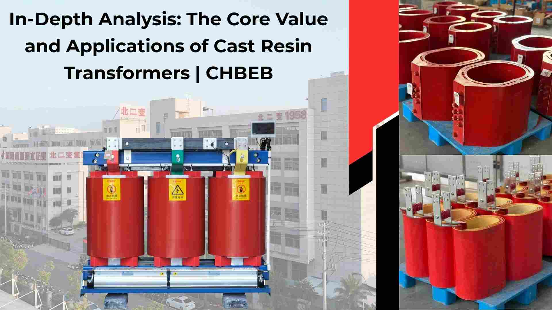
Cast Resin Transformer: Definition, Types, Benefits, Applications, Maintenance
Introduction
If you pick the wrong transformer, you could have safety problems, downtime, and exorbitant expenditures. Buyers often can’t decide between oil-based and dry-based solutions. Cast resin transformers are a safe, environmentally sustainable, and low-maintenance choice that works well for current projects in Southeast Asia, Africa, and the Middle East.
Technical Guide: Definition, Principles & Unique Advantages of Cast Resin Transformers
People are taking longer to make decisions because they are confused about cast resin transformers. If purchasers don’t comprehend clearly, they can spend too much or pick the wrong models. Here is how they function and why they are important.
What is a cast resin transformer, and what are its core concepts?
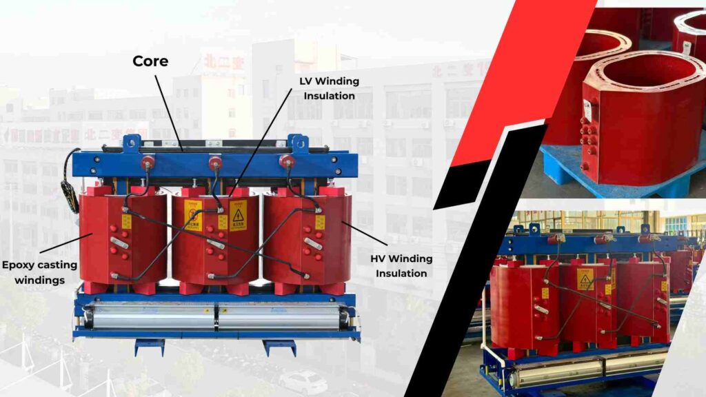
A cast resin transformer, also called an epoxy dry-type transformer or SCB transformer1, is a dry-type transformer that has its windings and core covered in epoxy resin2.
- Made via vacuum casting and making molds.
- Insulation that doesn’t catch fire and keeps moisture out.
- Gets rid of oil, which lowers the chance of leaks and fires.
👉 People in humid Southeast Asia generally choose cast resin over other materials to avoid problems caused by moisture.
Five main benefits of cast resin technology that make it better than other technologies
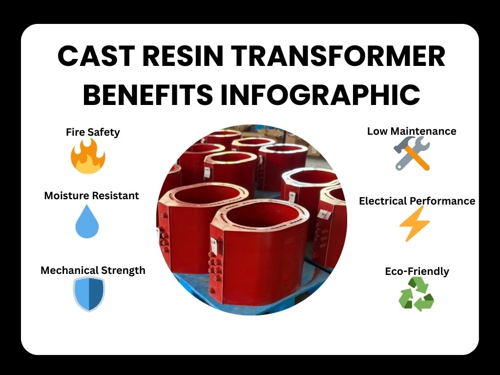
Why do so many people choose cast resin? Here are the five most important reasons:
- Epoxy resin is flame-resistant, so it is quite safe from fire.
- Great electrical performance; it can handle partial discharge3 and short circuits.
- No oil or regular fluid testing is needed, so it’s easy to take care of.
- Good for the environment—uses less energy and doesn’t pollute.
- Small and sturdy—resin encapsulation gives them exceptional mechanical integrity.
👉 These benefits make them a good alternative for hospitals, data centers, and metro projects.
Applications Guide: From Types to Scenarios, Find Your Ideal Match
Buyers often get confused when they don’t know what kinds of things are available and how to use them. If you guess wrong about someone’s ability or the situation, you could end up with a costly mismatch. Here are the categories and examples of how to use them.
SCB Series and Other Special Models Are Common Classifications
The SCB series (standard epoxy cast resin dry-type transformer) is the one that people use the most. There are other types, such as:
- SCB10/11—made to use less energy
- SCB14 has a low partial discharge and is very reliable.
- Special models made for usage in mining, maritime, or renewable energy
👉 Buyers should choose the proper SCB model based on the load profile and standards of their project.
Common Uses: Projects That Need to Pick Cast Resin Transformers
Cast resin transformers are great for places that need a lot of safety and dependability:
- Shopping malls, hospitals, and office towers are examples of indoor installations.
- Chemical facilities and refineries are areas where fires are likely to happen.
- Infrastructure projects include airports, metros, and data centers.
- IP54/IP65 protective enclosures for outdoor areas
👉 Cast resin units are preferred in African electrification schemes because they require less maintenance and are safe.
Maintenance Guide: The Truth About “Maintenance-Free” and Daily Care

A lot of people think that “maintenance-free” means no effort at all. Here, misunderstandings can shorten the life of things and make them less reliable. You still need to take care of it every day.
No need for maintenance for life? What You Need to Know About Daily Care
Transformers made of cast resin don’t need much upkeep, but they do need some. Important care includes:
- Regularly getting rid of dust to maintain airways clear
- Testing for partial discharge every so often
- Checks for insulation resistance and withstand voltage
- Checking the temperature during high loads
👉 Buyers don’t have to monitor the oil, but they do need to plan for testing at commissioning and regular overhauls.
Emerging Chinese Manufacturers
CHBEB — Reliable Partner for Distribution Transformers
With over 60 years of transformer manufacturing expertise, CHBEB has become one of China’s most trusted distribution transformer suppliers. The company operates two factories in Wenzhou, one in Nanjing, and an office in Beijing, ensuring both strong production capacity and responsive customer support.
What makes CHBEB stand out:
- Strict Quality Commitment: All raw materials are 100% new and high-grade — no recycled or downgraded components.
- Proven Reliability: A qualified supplier for the State Grid Corporation of China, with a spotless record of zero major accidents.
- 100% Product Testing: Every unit is fully tested before delivery to guarantee safety, efficiency, and long service life.
- Fast-Track Orders: Ability to fulfill urgent orders in as little as one week, helping customers meet tight project deadlines.
- Custom Inventory Planning: Flexible stocking and supply strategies designed to align with customer procurement schedules.
- Global Outlook: Rooted in China and expanding worldwide, CHBEB actively supports local agents and partners, including assistance with market-specific certifications.
- Flexible Customization: Tailored transformer designs for utilities, contractors, and industrial clients, with reliable quality and fast delivery.
👉 Looking for a distribution transformer manufacturer that combines Chinese manufacturing strength with international standards?Contact CHBEB for a tailored solution or Download our full transformer catalog here.
Conclusion
Choosing the right cast resin transformer is not just about fire safety—it’s about ensuring long-term reliability, compliance, and cost control for your project.
✅ Key takeaway for buyers:
- Match the right SCB model to your load profile and standards.
- Verify IEC/ISO certifications and request partial discharge reports.
- Plan ahead for commissioning tests and periodic checks.
With 60+ years of experience, CHBEB supports global partners with certified solutions and proven export expertise, helping you secure reliable performance in 2025 and beyond.
📞 Contact CHBEB today for the 2025 cast resin transformer price list and technical catalog.
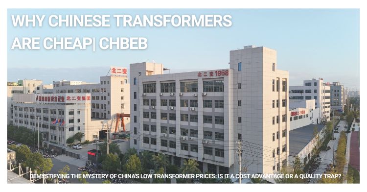
Demystifying the Mystery of China’s Low Transformer Prices: Is It a Cost Advantage or a Quality Trap?
Introduction
Prices that are excessively high affect budgets, but prices that are too low make people wonder. A lot of people throughout the world want to know why Chinese transformers are so cheap. Is it real cost strength or a risk that isn’t obvious? This guide tells you the reality about pricing and how it works in export markets including Southeast Asia, Africa, and the Middle East.
The positive factor behind the price advantage: the real strength of Made in China
People generally think that cheap things are bad, however not all cheap things are bad. The ecosystem in China really helps with costs, which is very important for those in Southeast Asia, Africa, and the Middle East who buy power distribution transformers.
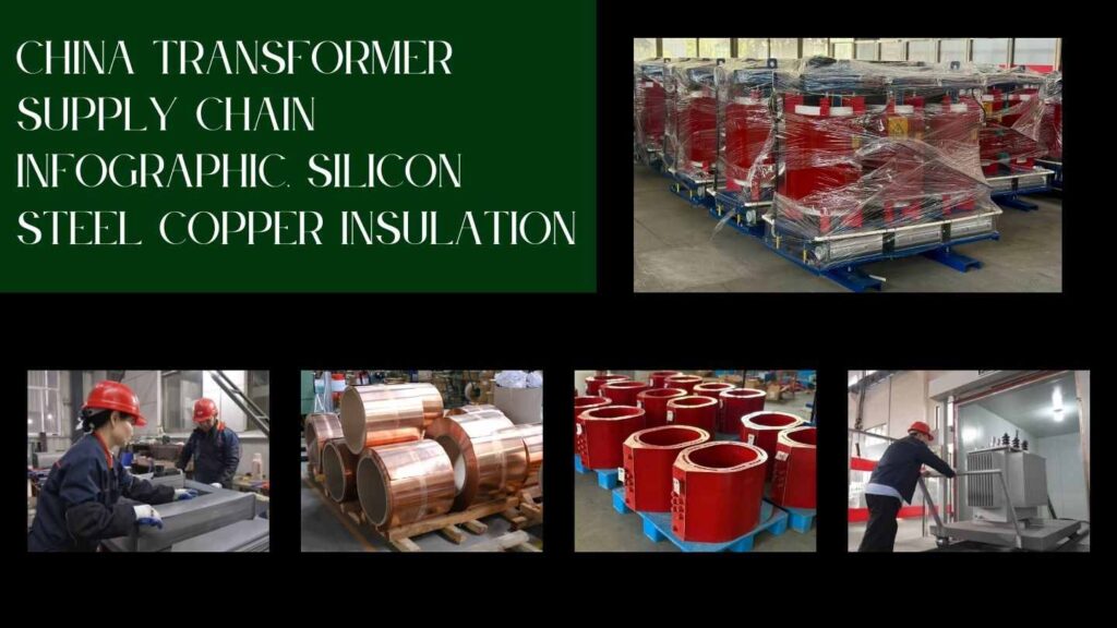
Full industrial chain and mass production
Costs go higher when supply chains are broken up. An integrated electrical industry is good for China because
- Silicon steel, copper, and insulation are all core materials that come from nearby sources.
- There are a lot of tap changers, bushings, and radiators in Wenzhou, Nanjing, and Xi’an.
- Mass production: one batch may be used for more than one project, which lowers the cost per unit.
👉 This synergy makes Chinese distribution transformer1 providers appealing for bids from African utilities, grid upgrades in Southeast Asia, and industrial growth in the Middle East.
Depending on size and features, the price of a typical Chinese power distribution transformer in 2025 will be between USD 20 and 100 per kVA FOB China.
The relative advantage of labor over operating costs
Labor prices go up, although they are still lower than in the U.S. or Europe. When combined with good operations, this lets:
- Faster turnaround (very important for efforts to bring electricity to rural areas in Africa)
- OEM/ODM flexibility (important in Southeast Asian EPC contracts)
- Large-capacity projects on a large scale (required in oil and gas installations in the Middle East)
📌 Insight: It’s not just “cheap labor,” but a system that works well and is ready to export.
Be careful: the dangers of giving up quality for low costs
Some exporters lower the quality of their goods to get better pricing, which causes challenges in export markets. For instance, African projects can have problems with transformers breaking down in isolated places, and Middle Eastern buyers might get too hot in desert settings.
“Cutting corners” when it comes to raw materials
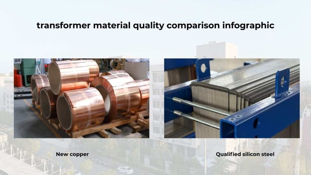
Performance is based on raw materials:
- Lower-quality silicon steel means more no-load losses, which is bad for Southeast Asian grids with increased demand.
- Recycled copper2 can get too hot and last less time (a problem for electrifying rural areas in Africa)
- Insufficient insulation results in partial discharge3 and safety risks, posing dangers in Middle Eastern industrial facilities.
👉 This is really crucial in Southeast Asia, where the weather is humid and bad insulation makes things break down faster.
Make the process of making things and testing them easier.
Some exporters that don’t charge much may bypass type tests or cut down on drying time. It saves money, but it also causes:
- Failures in tropical humidity in Southeast Asia
- African mini-grids have trouble keeping their voltage stable.
- Less reliable when temperatures in the Middle East are quite high in the desert
❌ You can’t skip tests on global projects.
How to find: Look for a Chinese transformer that is really cheap
The good news is that a lot of serious Chinese distribution transformer vendors sell trustworthy products all over the world. Finding them helps make sure both the pricing and the quality.
Main indicators: credentials, qualifications, and experience with projects
Find vendors who have a history of successful exports:
- Southeast Asia: IEC-certified transformers for charging electric vehicles and distribution grids
- Africa: listings of licensed vendors by utilities, successful programs to bring electricity to rural areas
- Middle East: transformers that can handle high temperatures, oil and gas EPC approvals
Real reliability comes from certifications and case studies of exports.
The ability to ask questions and understand contract terms
To avoid problems in international trade, purchasers should:
- Ask for two quotes, like 0.6 vs. 1.1 lost material.
- Make sure you know how long it will take to deliver (particularly important for initiatives in Africa and Southeast Asia).
- Define the terms of the warranty and after-sales service (very important in long-term contracts in the Middle East)
Tip: Strong contracts and proven export cases make deals that are safe and cost-effective.
CHBEB — Reliable Partner for Distribution Transformers
With over 60 years of transformer manufacturing expertise, CHBEB has become one of China’s most trusted distribution transformer suppliers. The company operates two factories in Wenzhou, one in Nanjing, and an office in Beijing, ensuring both strong production capacity and responsive customer support.
What makes CHBEB stand out:
- Strict Quality Commitment: All raw materials are 100% new and high-grade — no recycled or downgraded components.
- Proven Reliability: A qualified supplier for the State Grid Corporation of China, with a spotless record of zero major accidents.
- 100% Product Testing: Every unit is fully tested before delivery to guarantee safety, efficiency, and long service life.
- Fast-Track Orders: Ability to fulfill urgent orders in as little as one week, helping customers meet tight project deadlines.
- Custom Inventory Planning: Flexible stocking and supply strategies designed to align with customer procurement schedules.
- Global Outlook: Rooted in China and expanding worldwide, CHBEB actively supports local agents and partners, including assistance with market-specific certifications.
- Flexible Customization: Tailored transformer designs for utilities, contractors, and industrial clients, with reliable quality and fast delivery.
👉 Looking for a distribution transformer manufacturer that combines Chinese manufacturing strength with international standards?Contact CHBEB for a tailored solution or Download our full transformer catalog here.
FAQ
Q1: Why are Chinese transformers cheaper?
Because of China’s complete industrial chain, mass production, and efficient operations—not just labor cost.
Q2: What is the typical price of distribution transformers in 2025?
Prices range from USD 20–100/kVA FOB China. For example, a 1000 kVA 11/0.4 kV transformer costs USD 25,000–70,000 depending on materials and standards.
Q3: How can overseas buyers ensure quality?
Check IEC/ANSI certifications, ask for type test reports, and verify export project references.
Q4: What contract terms should buyers confirm?
Delivery timeline, warranty, after-sales service, and loss material options (0.6 vs. 1.1).
Conclusion
Chinese transformers in 2025 are cheap for structural reasons—integrated supply chains, local materials, and mass production. But low price alone can hide quality risks.
✅ For buyers in Southeast Asia, Africa, and the Middle East, the real focus should be:
- Certifications & References — verify IEC/ANSI reports and proven export projects.
- Clear Contracts — lock in delivery, warranty, and loss guarantees.
- After-Sales Support — ensure service and spare parts availability.
Final takeaway: Don’t chase the lowest price. The smarteDistribution transformerst choice in 2025 is to plan early, vet suppliers carefully, and secure both competitive cost and dependable delivery.
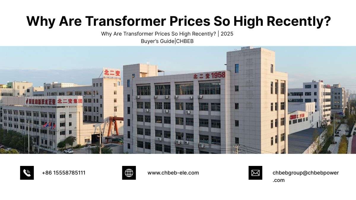
Why Are Transformer Prices So High Recently?
Introduction
There are delays in delivery and budgets are tight. Why? Prices for transformers have gone up a lot lately, which has shocked purchasers all across the world. This buyer’s guide for 2025 explains why transformer prices are so expensive and how to find dependable transformer suppliers in China who can offer you a good deal.
1) The cost of raw materials is going up
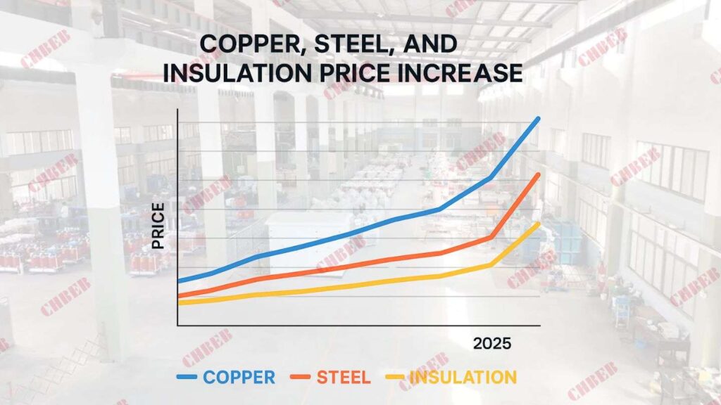
Copper, electrical steel, and insulation materials are the main parts of making transformers, and all of them have gotten more expensive:
- Copper1: The prices of copper windings are still close to their highest levels in years.
- Grain-oriented2 silicon steel is in short supply, which raises the cost of cores.
- Insulation and resin: Epoxy, kraft paper, and other dielectrics follow the rise in petrochemical and energy prices
This means that the base cost of all oil-immersed transformers and dry-type transformers goes up.
2) Growing demand over the world
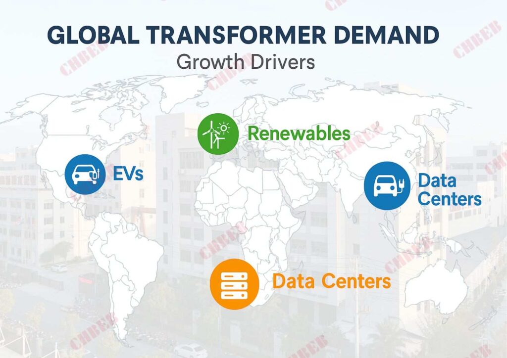
Worldwide, demand is greater than supply:
- Solar, wind, and storage projects all need step-up/step-down transformers.
- Charging networks and distribution upgrades bring extra load to EV infrastructure.
- Hyperscale developments in the U.S. and Southeast Asia are causing record orders in data centers.
The spike raises transformer prices in 2025 and makes lead times longer.
3) Problems in the supply chain
Production hasn’t grown fast enough to keep up with demand:
- The time it takes to get massive power transformers has gone from 6–12 months to 18–36 months.
- There are always choke points since there isn’t enough core steel and huge units around the world.
- Shipping prices, port congestion, and logistical costs are still high.
4) More strict rules and standards
- Efficiency rules (IEC/DOE) call for more copper and steel of a better grade.
- Fire safety standards make cast-resin dry-type units more popular for interior projects, although they cost more.
- Tariffs and export controls on electrical steel or finished transformers make things more expensive in the area.
5) The cost of energy and inflation
- Inputs for factories: more electricity, labor, and overhead.
- Transport: Shipping heavy equipment and getting it to the last mile are both a lot more expensive than they were before 2020.
A look at transformer prices in 2025
| Transformer Type | Typical Capacity | Price Range (FOB China) | Notes |
|---|---|---|---|
| Dry-Type (Cast Resin)3 | 50–3150 kVA | USD 40–90/kVA | Hospitals, metros, data centers |
| Oil-Immersed | 50–25,000 kVA | USD 20–50/kVA | Utilities, substations |
| Example: 1000 kVA Dry-Type (11/0.4 kV) | – | USD 40,000–70,000 | IEC/UL certified |
| Example: 1000 kVA Oil-Immersed (11/0.4 kV) | – | USD 25,000–40,000 | Widely used in grids |
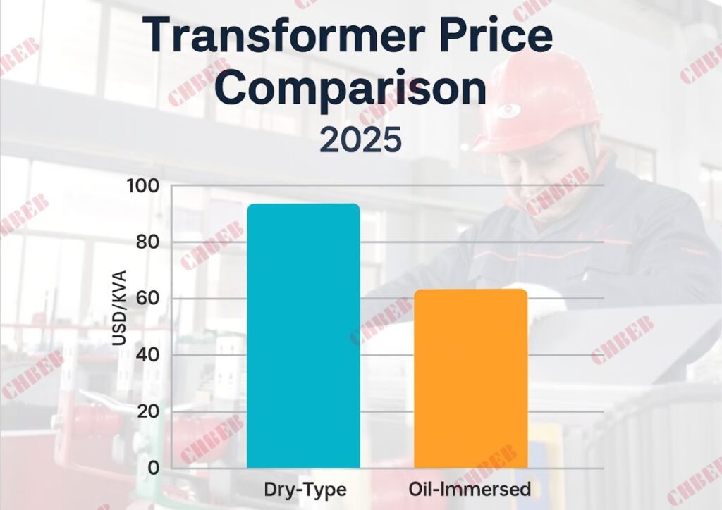
Prices depend on the type of copper or aluminum windings, the level of loss (0.6 vs. 1.1), and whether the product has IEC or UL certification.
What Buyers Will Be Able to Do in 2025
- Plan ahead: Place your order 6 to 12 months in advance to make sure you get a production slot.
- Look at 2–3 quotes from well-known transformer providers in China and compare them.
- Say what materials to use: Pick the insulation class, copper or aluminum windings, and core loss level.
- Lock pricing: Use fixed-price clauses to keep prices from changing too much.
- Check certifications like IEC, ISO, and UL to make sure they are compliant and accepted by the grid.
Quick Takeaway for the Buyer
- Prices are high because of the cost of raw materials, strong demand, and little supply.
- Expect things to be unstable until 2025.
- Smart sourcing from trustworthy suppliers helps lower the danger of transformer price 2025.
Emerging Chinese Manufacturers
CHBEB — Reliable Partner for Distribution Transformers
With over 60 years of transformer manufacturing expertise, CHBEB has become one of China’s most trusted distribution transformer suppliers. The company operates two factories in Wenzhou, one in Nanjing, and an office in Beijing, ensuring both strong production capacity and responsive customer support.
What makes CHBEB stand out:
- Strict Quality Commitment: All raw materials are 100% new and high-grade — no recycled or downgraded components.
- Proven Reliability: A qualified supplier for the State Grid Corporation of China, with a spotless record of zero major accidents.
- 100% Product Testing: Every unit is fully tested before delivery to guarantee safety, efficiency, and long service life.
- Fast-Track Orders: Ability to fulfill urgent orders in as little as one week, helping customers meet tight project deadlines.
- Custom Inventory Planning: Flexible stocking and supply strategies designed to align with customer procurement schedules.
- Global Outlook: Rooted in China and expanding worldwide, CHBEB actively supports local agents and partners, including assistance with market-specific certifications.
- Flexible Customization: Tailored transformer designs for utilities, contractors, and industrial clients, with reliable quality and fast delivery.
👉 Looking for a distribution transformer manufacturer that combines Chinese manufacturing strength with international standards?Contact CHBEB for a tailored solution or Download our full transformer catalog here.
FAQ
Q1: Why are transformer prices rising in 2025?
Copper/steel and insulation costs are higher, while demand from renewables, EVs, and data centers exceeds available supply.
Q2: How much do transformers cost now?
Oil-immersed: USD 20–50/kVA; Dry-type: USD 40–90/kVA. Example: 1000 kVA oil-immersed is USD 25,000–40,000.
Q3: Will prices go down soon?
Not immediately. Most analysts expect prices to stay high through 2025 due to persistent supply-demand imbalance.
Q4: How can buyers reduce costs?
Order early, compare multiple transformer suppliers in China, specify materials clearly, and negotiate fixed contracts.
Q5: Where to buy transformers in 2025?
Many buyers source from Asia—working with a vetted transformer supplier China offers competitive pricing, IEC-certified quality, and reliable lead times.
Q6: How long is transformer delivery in 2025?
Small units typically deliver in 2–3 months, while large power transformers may require 12–24 months, depending on supplier capacity.
Conclusion
Transformer prices remain high in 2025, but disciplined sourcing gives buyers control:
- Time: Place orders 6–12 months in advance to secure production slots and delivery dates.
- Technical: Specify winding material (copper/aluminum), loss class (0.6/1.1), and insulation grade to avoid vague quotations.
- Contractual: Request fixed-price clauses, IEC/UL reports, and third-party inspections to reduce risks.
- Service: Look beyond the initial price—evaluate after-sales support and spare parts availability.
✅ Key point: In an uncertain market, true competitiveness is not about chasing the lowest unit price, but about partnering with suppliers that ensure certified quality, predictable delivery, and long-term peace of mind.
With over 60 years of expertise, CHBEB has supported Belt and Road and global clients with tailored transformer solutions, helping buyers secure cost stability and reliable delivery despite volatile market conditions.
Introduction
Power outages and broken equipment can lead to expensive downtime. A lot of people don’t understand what pad-mounted transformers1 are or how they are different from other methods of distribution. This guide tells worldwide customers what a pad-mounted transformer is, how it works, its benefits, its uses, and the average prices they can expect to pay in 2025.
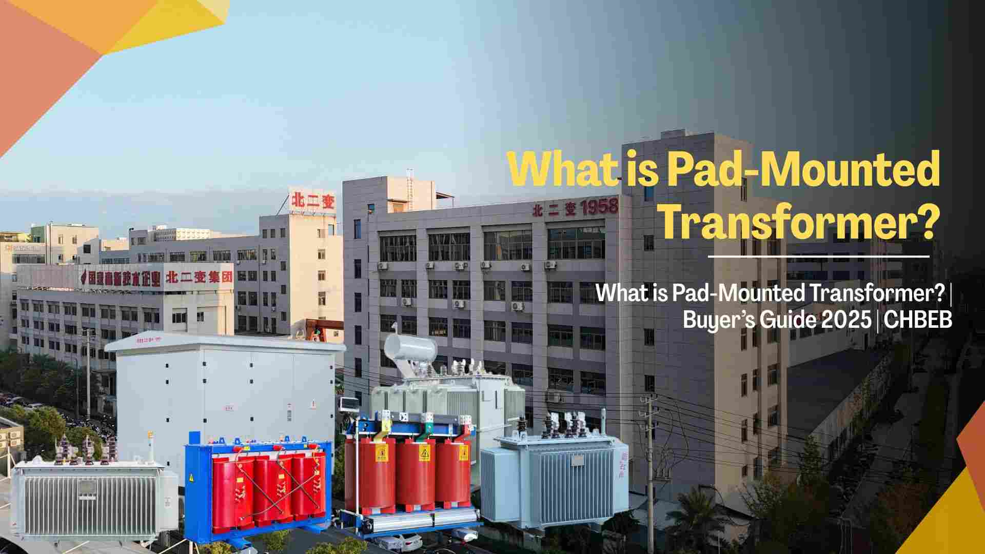
What is a Pad-Mounted Transformer?
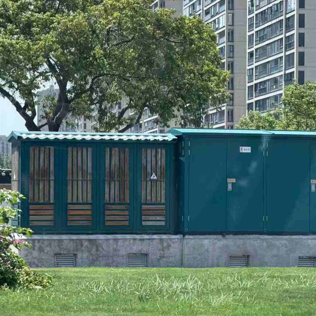
A pad-mounted transformer is a kind of distribution transformer that is put outside on a concrete platform and kept safe in a sealed, tamper-proof steel cabinet. It connects to wires that run underground and lowers the medium voltage (up to 35 kV) to a level that users may use.
Pad-mounted transformers are safe to put in public places like neighborhoods, malls, and data centers because all of the live parts are enclosed inside the cabinet. They don’t need a gated enclosure.
👉 A pad-mounted transformer is a distribution transformer that is fixed on the ground, loaded with oil, and kept in a secure cabinet. It is commonly used for subterranean electricity distribution.
Structure & Working Principle
Pad-mounted transformers are usually oil-immersed units designed for outdoor environments.
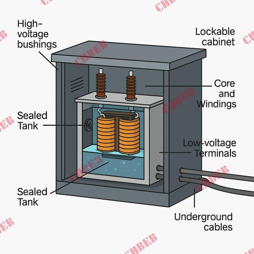
Key components include:
- Core & Windings – Step voltage up or down.
- Insulating Oil2 – Provides cooling and electrical insulation.
- Sealed Tank – Protects the core and windings.
- Lockable Cabinet – Houses high- and low-voltage terminals.
- Fuses & Switches – Provide overload and fault protection.
- Concrete Pad – Provides stable installation on the ground.
How it works:
Incoming medium-voltage cables enter the high-voltage compartment → power is stepped down through the transformer core and windings → low-voltage output is distributed to buildings, homes, or facilities.
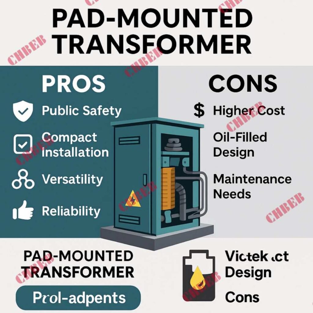
Advantages of Pad-Mounted Transformers
✅ Public Safety – No exposed live parts, secure steel cabinet.
✅ Compact Installation – No need for fencing, suitable for urban and residential areas.
✅ Versatility – Available in both single-phase and three-phase, covering 15–5000 kVA.
✅ Reliability – Designed for underground distribution with built-in fuses and switches.
✅ Aesthetics – Blends into public spaces, avoiding large substations.
Disadvantages to Consider
⚠️ Oil-Filled Design – Requires fire protection and environmental precautions.
⚠️ Maintenance – Regular oil testing and inspection are needed.
⚠️ Higher Cost – More expensive than pole-mounted transformers.
Applications of Pad-Mounted Transformers
- Residential Neighborhoods – Safe distribution in housing developments.
- Commercial Complexes & Malls – Compact power supply near buildings.
- Hospitals & Data Centers – Reliable, secure, low-noise operation.
- Industrial Sites – Step-down power for medium-sized factories.
- Infrastructure Projects – Airports, schools, metro stations.
Pad-Mounted Transformer vs. Other Types
| Feature | Pad-Mounted Transformer | Pole-Mounted Transformer | Dry-Type Transformer |
|---|---|---|---|
| Installation | Ground-mounted on concrete pad | Mounted on utility poles | Indoor (resin/air cooling) |
| Safety | High – cabinet enclosed | Medium – exposed on pole | Very High – no oil |
| Typical Rating | 15–5000 kVA | 10–500 kVA | 50–3150 kVA |
| Location | Outdoor, urban/public | Outdoor, rural | Indoor, sensitive areas |
Pad-Mounted Transformer Price 2025
Typical pad-mounted transformer prices in 2025 range from USD 25–70/kVA FOB China, depending on rating, copper/aluminum windings, and standards.
- Small units (100–500 kVA): USD 30–50/kVA
- Medium units (1000–2500 kVA): USD 35–60/kVA
- Large units (3000–5000 kVA): USD 40–70/kVA
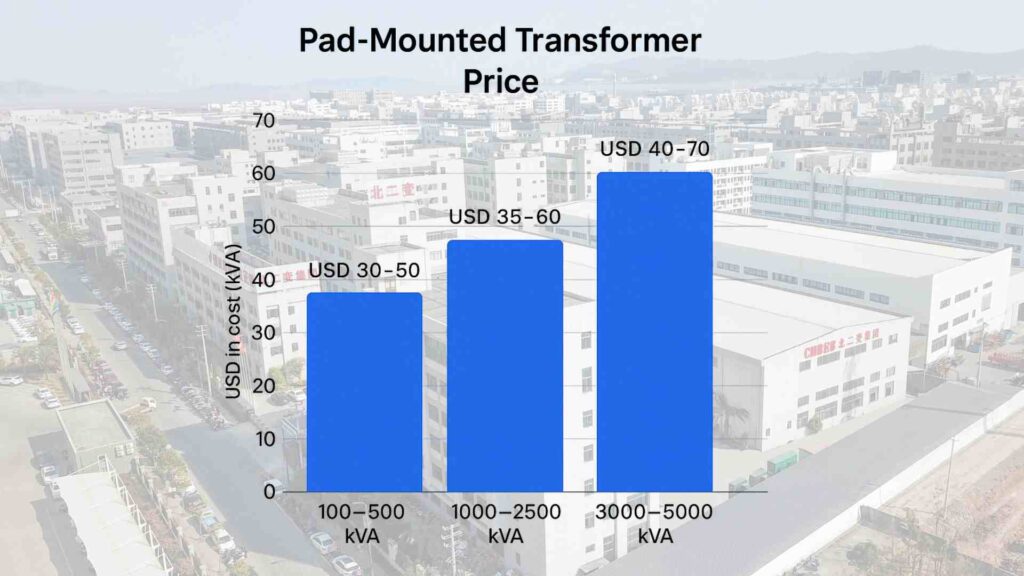
👉 Example: A 1000 kVA 13.8/0.48 kV pad-mounted transformer typically costs USD 40,000–55,000 FOB China.
Buyer’s Quick Takeaway
- Choose pad-mounted if you need outdoor, public-area distribution with safe underground cabling.
- Consider oil testing and fire protection when planning maintenance.
- Compare suppliers in China—a reliable pad-mounted transformer supplier can save costs and ensure IEC/ANSI compliance.
FAQ – Pad-Mounted Transformers 2025
Q1: What is a pad-mounted transformer?
A ground-mounted, oil-filled distribution transformer enclosed in a steel cabinet, connected to underground cables.
Q2: What are the advantages?
Safety, compact installation, reliability, and suitability for public areas.
Q3: Where are they used?
In neighborhoods, malls, hospitals, schools, airports, and industrial facilities.
Q4: What is the price of pad-mounted transformers in 2025?
Typically USD 25–70/kVA FOB China. Example: 1000 kVA unit costs USD 40,000–55,000.
Q5: Pad-mounted vs. pole-mounted—what’s the difference?
Pole-mounted are cheaper but less safe; pad-mounted are safer, enclosed, and used in public spaces.
Q6: How to buy a reliable pad-mounted transformer from China?
Check IEC/ANSI certifications, compare quotes from multiple suppliers, and request type-test reports before purchase.
Conclusion
Pad-mounted transformers are compact, secure, and reliable distribution solutions for public and commercial power systems. They combine safety, versatility, and modern aesthetics, making them essential for underground distribution networks worldwide.
📞 Contact us today if you want to buy pad-mounted transformer from China. Get a 2025 price list, lead time, and technical specifications tailored to your project.
Learn More
Looking for the right dry-type transformer for your project? Download our latest product catalog or browse our product categories to find reliable solutions tailored to your needs.
What is Dry Transformer?
Fire safety, oil-free operation, and minimal upkeep are driving demand. Buyers confused between oil-immersed and dry designs risk costly mistakes. The safer answer? Dry-type transformers1, now a global standard for indoor projects.
What is a Dry-Type Transformer?
A dry-type transformer is one where the core and windings are cooled by air or resin instead of oil. With no flammable liquid, it reduces fire hazards and simplifies installation.
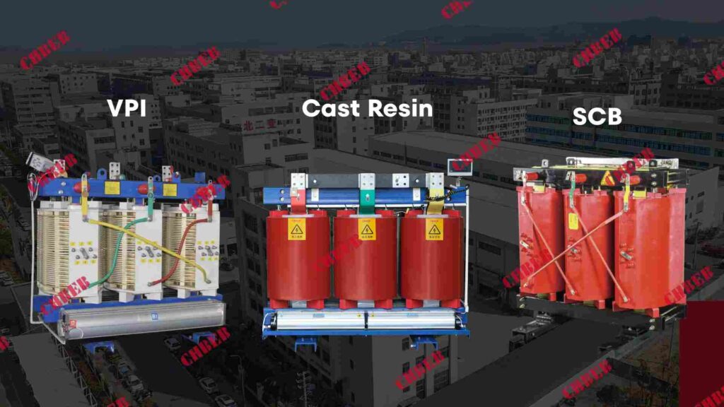
- VPI2 (Vacuum Pressure Impregnated) – Coils varnished under vacuum and pressure.
- Cast Resin – Windings fully encapsulated, moisture- and dust-resistant.
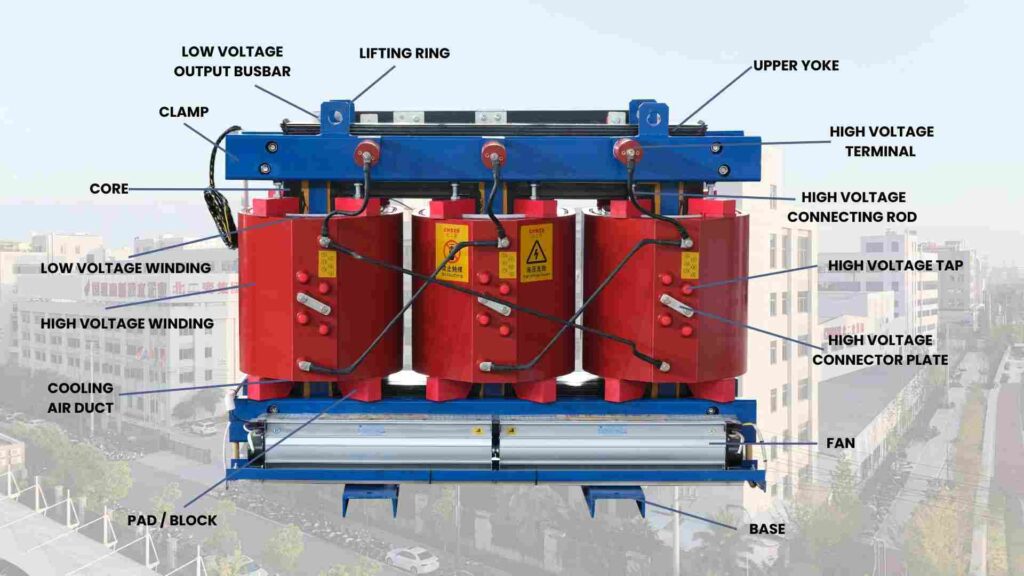
Structure & Working Principle
Buyers fear overheating and fire risks. Dry-type transformers eliminate these by using air or resin insulation.
- Core & Windings – Copper/aluminum conductors with silicon steel.
- Insulation – Resin/varnish to block partial discharge.
- Enclosure – Shields from dust and contact.
- Cooling – Natural air (AN) or fan-assisted (AF).
Principle: Load generates heat → heat released to air → optionally cooled by fans → stable, fire-safe operation.
Types of Dry-Type Transformers
Choosing the wrong type raises risks. Buyers often select:
- VPI Transformer – Affordable, serviceable.
- Cast Resin Transformer – Fully encapsulated, robust in humidity.
- SCB Transformer – Popular resin type in IEC/GB markets.
Cooling: AN (natural air convection) or AF (fans assist cooling for higher load).
✅ Advantages of Dry-Type Transformers
- Fire-Safe – Non-flammable insulation.
- Reliable Indoors – Trusted in hospitals, metros, data centers.
- Eco-Friendly – No oil leaks, low environmental risk.
- Compact Footprint – Easy to install in tight spaces.
- Moisture Resistant – Cast resin excels in tropical regions.
⚠️ Disadvantages to Consider
- Higher Price – More costly than oil-immersed.
- Capacity Limits – Typically 50–3,150 kVA.
- Service Life – Around 20–25 years.
- Cooling Limits – Less efficient for extreme heavy loads.
Applications
Dry-type transformers are ideal for:
- Hospitals & Schools – Safer for public buildings. In Africa, adopted for indoor hospital and school projects.
- Data Centers – Dust-proof, reliable. In Southeast Asia, increasingly used in hyperscale centers for fire compliance.
- Underground Metro & High-Rise Buildings – Compact design fits tight basements.
- Commercial Spaces – Airports, malls, offices in the Middle East.
With demand rising, global buyers prefer to buy dry-type transformer from China, where certified factories act as reliable dry transformer supplier China partners.
Price Guide for Dry-Type Transformers

| Capacity | Price Range (FOB China) | Notes |
|---|---|---|
| 50–500 kVA | USD 40–60/kVA | Small commercial use |
| 1000–2500 kVA | USD 60–90/kVA | Hospitals, data centers |
| Example: 1000 kVA 11/0.4 kV | USD 40,000–70,000 | IEC/UL certified |
Dry-Type vs. Oil-Immersed Transformer
| Feature | Dry-Type Transformer | Oil-Immersed Transformer |
|---|---|---|
| Cooling Medium | Air / Resin | Mineral / Synthetic Oil |
| Fire Safety | Higher (non-flammable) | Lower (flammable oil) |
| Maintenance | Minimal | Regular oil testing |
| Service Life | 20–25 years | 25–30 years |
| Typical Capacity | 50–3,150 kVA | 50–25,000 kVA |
| Typical Use | Indoor, public infrastructure | Outdoor, utility-scale grids |

Buyer’s Quick Takeaway
- Dry-type = safe, eco-friendly, compact footprint.
- Oil-immersed = outdoor, high-capacity, longer life.
- Match transformer type to project scale and safety codes.
FAQ
Q1: What is a dry-type transformer?
A transformer cooled by air or resin instead of oil, reducing fire risk and maintenance.
Q2: Main advantages?
Fire-safe, low maintenance, eco-friendly, compact, reliable indoors.
Q3: Where are they used?
Hospitals, schools, data centers, metros, malls, and airports. In Africa, schools and hospitals increasingly adopt dry-type transformers for safer indoor operations. In Southeast Asia, hyperscale data centers adopt them for fire compliance.
Q4: Price range?
USD 40–90/kVA FOB China. Example: 1000 kVA ~ USD 40,000–70,000. Buyers should compare quotes from multiple dry transformer suppliers in China to balance cost and quality. CIF quotes available.
Q5: How to choose a reliable supplier in China?
Check IEC/ISO certifications3, verify project references, and request test reports before placing orders with a dry transformer supplier China.
Conclusion
Dry-type transformers offer fire safety, eco-friendly design, and reliable indoor performance, making them the preferred choice for hospitals, metros, data centers, and high-rise projects worldwide. Compared to oil-immersed models, they trade higher upfront cost for safety, compliance, and low maintenance—critical factors for modern infrastructure.
✅ Final takeaway: Choose dry-type when fire safety, compact footprint, and indoor reliability matter most; choose oil-immersed for large outdoor grids and heavy-duty capacity.
👉 If you plan to buy dry-type transformer from China, request our 2025 price list and delivery schedule today. Partner with a trusted dry transformer supplier in China to secure cost, ensure compliance, and guarantee on-time delivery.
- Dry-Type Transformer Overview ↩︎
- Understanding Vacuum Pressure Impregnation Transformers ↩︎
- IEC Standards for Transformers ↩︎
Learn More
Looking for the right dry-type transformer for your project? Download our latest product catalog or browse our product categories to find reliable solutions tailored to your needs.
What is Oil-Immersed Transformer?

Power outages and overheating make things less efficient and more expensive. A lot of purchasers are unsure whether to go with a dry-type or oil-immersed design. What is the answer? Oil-filled transformers, also termed oil-immersed transformers1, are still the best choice for dependable, high-capacity power systems.
What is a transformer that is immersed in oil?

Bad choices make things less reliable and waste money. An oil-immersed transformer is a power unit with a core and windings that are completely covered in insulating oil. This insulating fluid, which is why the transformer is often called an oil-filled transformer, cools and protects the transformer from electricity. This makes it perfect for industrial and utility networks.
How it works and how it is built
Heat makes transformers last less long. Oil immersion keeps things from breaking down by soaking up and spreading out extra heat.
- Core and windings change the voltage.
- Insulating Oil: Cools and insulates.
- Sealed Tank: Keeps air and moisture from getting in.
- Radiators let heat out into the air.
- Conservator and Breather: Control the growth of oil and keep moisture in check.
How it works: Heat goes into the oil, which then naturally or with pumps moves around. The heat then goes out through radiators, and the cooled oil goes back to the windings.
Different kinds of oil-immersed transformers
Choosing the wrong type can make things less efficient. There are two main types of oil-immersed transformers: those that cool down and those that don’t.
By how it cools:
- ONAN2: Oil and air flow naturally.
- ONAF—Fans help cool oil and air.
- OFAF: Oil pumps and fans for big machines.
- OFWF stands for “oil-to-water cooling for plants.”.
The manner the tank is built:
- Type of Seal: Completely closed, less oxidation, and less work to keep up.
- Type of conservator: an expansion tank with a breather, which is used in HV systems.
Benefits of Transformers That Are Immersed in Oil
- Better Cooling: Oil takes heat away better.
- Strong insulation: stable dielectric protection.
- Wide range of capacities, from 50 kVA to 25,000 kVA.
- Long service life—usually 25 to 30 years.
- Proven Reliability: Oil-immersed transformers are still the most important part of networks around the world.
⚠️ Things to think about that are bad
- Fire Hazard: Oil can catch fire, thus safety systems are needed.
- Regular oil testing and filtering are needed for maintenance.
- Environmental Risk: Oil spills can damage water and soil.
- Size and weight: larger footprint than dry kind.
Applications
Using the wrong transformer makes things less efficient and costs more. The ideal use for oil-immersed transformers is:
- Power plants and substations—step-up and step-down operations.
- Industrial Buildings—Heavy-Duty Supply
- Urban and rural grids provide reliable power to communities.
- Projects for renewable energy include connecting solar and wind power to the grid.
- Markets for export— Exported a lot to Southeast Asia, Africa, and the Middle East. China is a prominent supplier of oil-filled transformers because these areas value low prices and IEC-certified devices. Russia and the countries along the Belt and Road are also quickly becoming big purchasers of Chinese oil-immersed transformers.
Oil-Immersed vs. Dry-Type Transformer
| Feature | Oil-Immersed Transformer | Dry-Type Transformer |
|---|---|---|
| Cooling Medium | Mineral / Synthetic Oil | Air / Resin |
| Fire Safety | Lower (flammable) | Higher (non-flammable) |
| Maintenance | Regular oil testing | Minimal |
| Service Life | 25–30 years | 20–25 years |
| Typical Capacity | 50–25,000 kVA | 50–3,150 kVA |
| Typical Use | Outdoor, high-capacity projects | Indoor, sensitive locations |
Buyer’s Quick Takeaway
- Oil-immersed (oil-filled) means that it is made for outdoor use, has a lot of space, and lasts a long time.
- Dry-type means it may be used inside, is safer, and doesn’t need much upkeep.
- For the best return on investment, choose the right type of transformer for the project environment.
FAQ
Q1: What is an oil-immersed transformer?
It is a transformer where windings and core are submerged in insulating oil for cooling and insulation.
Q2: Main advantages of oil-immersed transformers?
Efficient cooling, strong insulation, wide capacity (50–25,000 kVA), and 25–30 years service life.
Q3: Where are they used?
In substations, power plants, industrial facilities, grids, and renewable projects.
Q4: What is the price range of oil-immersed transformers?
Price range is typically USD 20–50/kVA FOB China. For example, a 1000 kVA 11/0.4 kV oil-immersed transformer costs USD 25,000–40,000. CIF quotes available upon request depending on destination.
Conclusion
Oil-immersed transformers remain the backbone of power systems worldwide thanks to their efficient cooling, strong dielectric insulation, wide capacity range (50–25,000 kVA), and 25–30 years of service life. Compared with dry-type designs, they are the preferred solution for outdoor substations, industrial plants, and renewable projects that demand high reliability and heavy-duty performance.
For global buyers, especially in Southeast Asia, Africa, Russia, and Belt & Road countries, China offers oil-immersed transformers with competitive pricing and IEC-certified quality.
✅ Final takeaway: Define your project’s duty, environment, and budget—then select the oil-immersed transformer model that minimizes risk and maximizes ROI.
👉 If you plan to buy oil-immersed transformer from China, contact CHBEB today for specifications, pricing, and delivery schedules. Secure your order early to avoid 2025 price fluctuations and shipping delays.
Learn More
Looking for the right dry-type transformer for your project? Download our latest product catalog or browse our product categories to find reliable solutions tailored to your needs.
