Introduction
If you don’t have a clear catalog, you can end up with the wrong solar transformers1, which could cause delays and cost you money. When your inverters or grid don’t match up with kVA and voltage, things get even more confusing. Use this guide to look up specs, check what’s in stock, and get quick, accurate prices.
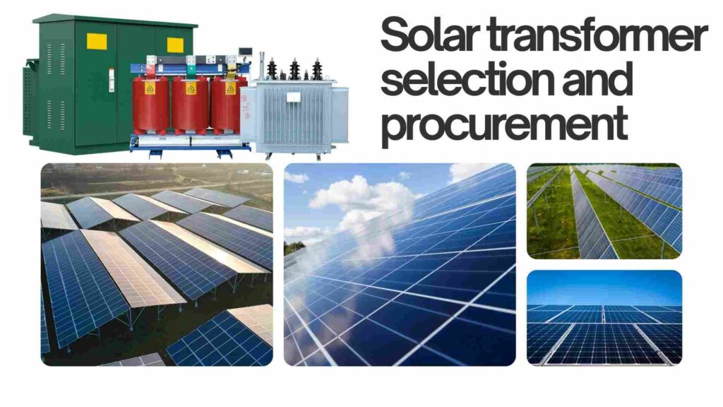
Find Your Solar Transformer: Browse by KVA and Voltage
Guessing leads to things being too big, losing money, and needing to make changes. As deadlines slide, stakeholders get angry. You may quickly narrow down your choices to the proper three-phase or single-phase devices by starting with a basic matrix of kVA and voltage.
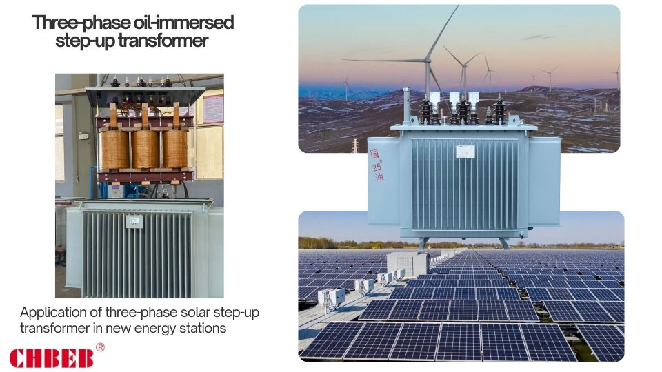
Transformers for Three-Phase Solar
Three-phase pad-mounted or station-type devices may manage utility-scale PV blocks, wind turbines, and C&I microgrids where balanced loads, motor/VFD compatibility, and power quality control are required.
| kVA/MVA Class | Typical Primary (MV) | Typical Secondary | Common Vector Group2 | Use Case | Typical Availability |
|---|---|---|---|---|---|
| 150–500 kVA | 11 / 13.8 / 22 kV | 480/277 V or 400/230 V | Dyn11 / YNd11 | C&I rooftop PV blocks, microgrids | Standard builds; select quick-ship SKUs |
| 750–2000 kVA | 22 / 24.9 / 33 kV | 690 V, 480/277 V, or 400/230 V | Dyn11 (triplen blocking) | Utility-scale string inverter skids | Made-to-order with stocked components |
| 2.5–5 MVA | 33 / 34.5 / 35 kV | 690 V or 800–1000 V class | Ynd or Dyn per grid code | Central inverter stations, collection | Project builds; scheduled production slots |
- Recommended choices include dead-front terminations, MV surge arresters, off-circuit taps (±2×2.5%), copper windings for high duty, and natural ester fluid for fire safety.
- Design notes: Set %Z to balance fault duty and regulation, and check with the utility to make sure the neutral and ground are correct.
Single-Phase Solar Transformers
Single-phase pad-mounted units can handle low to moderate loads, agricultural PV, and residential areas where keeping things simple, taking up less space, and keeping costs down are important.
| kVA Class | Typical Primary (MV) | Typical Secondary | Configuration | Use Case | Typical Availability |
|---|---|---|---|---|---|
| 25–100 kVA | 7.2 / 12.47 / 13.2 kV | 240/120 V or 480/240 V | Single-phase, split-phase | Small PV tie-ins, farms | Common stock on standard voltages |
| 167–500 kVA | 12.47 / 24.9 kV | 480/240 V or 240/120 V | Single-phase | Community solar, light C&I | Build-to-order with quick components |
- When to choose: loads that are stable and predictable, three-phase equipment that is limited, and strict siting restrictions.
- Things to think about: Make plans for more EVs and HVAC systems; think about switching to three-phase feeders if the number of customers goes up.
Get a Detailed Quote & Check Inventory
Vague RFQs lead to delays, change orders, and bad prices. Teams spend weeks going over specs. To get quick, apples-to-apples quotations, use a structured request that answers engineering and procurement questions right away.
A Simple Step-by-Step Guide to the Quote Process
- Share load data: peak/diversified kVA, duty cycle, ramp behavior, harmonics limitations, and growth prediction.
- Define voltages: MV primary (like 11/22/33/35 kV) and LV secondary (like 690 V, 480/277 V, or 400/230 V).
- Choose the type of configuration: three-phase or single-phase; vector group (Dyn, YNd); grounding method; and %Z target.
- Set taps and protection: Tap range (for example, ±2×2.5%); bayonet/CL fusing; surge arresters; and fault indications.
- Environment: ambient/altitude, corrosion category (C4/C5-M), noise limits, animal guards, and ingress protection.
- Copper vs. aluminum windings; ONAN/ONAF; mineral vs. natural ester fluid; dry-type if liquid is limited.
- Compliance and tests: IEC/IEEE3 rules that apply; routine, type, and special tests; and documentation that needs to be delivered.
- Logistics: The date the ship must leave, the constraints on the pad/loading, how to get to the delivery, the warranty, and the spare parts kit.
Tip: To evaluate offers on total cost instead than sticker price, change guaranteed loss numbers (no-load/load) into annual energy cost.
The current state of the inventory
When it’s not obvious when something will be available, buying timeframes become pushed back. Surprises cause expensive rework. We break up the inventory so you can plan your scope and timeline early.
- In-stock SKUs: Popular kVA/voltage combinations that can be shipped quickly; great for quick replacements.
- Quick-build: Standard designs put together from supplied cores, coils, and cabinets; predictable shipping windows in the near future.
- Build-to-order: Fully personalized ratings, taps, and accessories are set to be made; this is best for engineered projects.
To double-check the exact amounts, lead times, and appropriate accessories (elbows, arresters, connections), ask for the most recent pick-list.
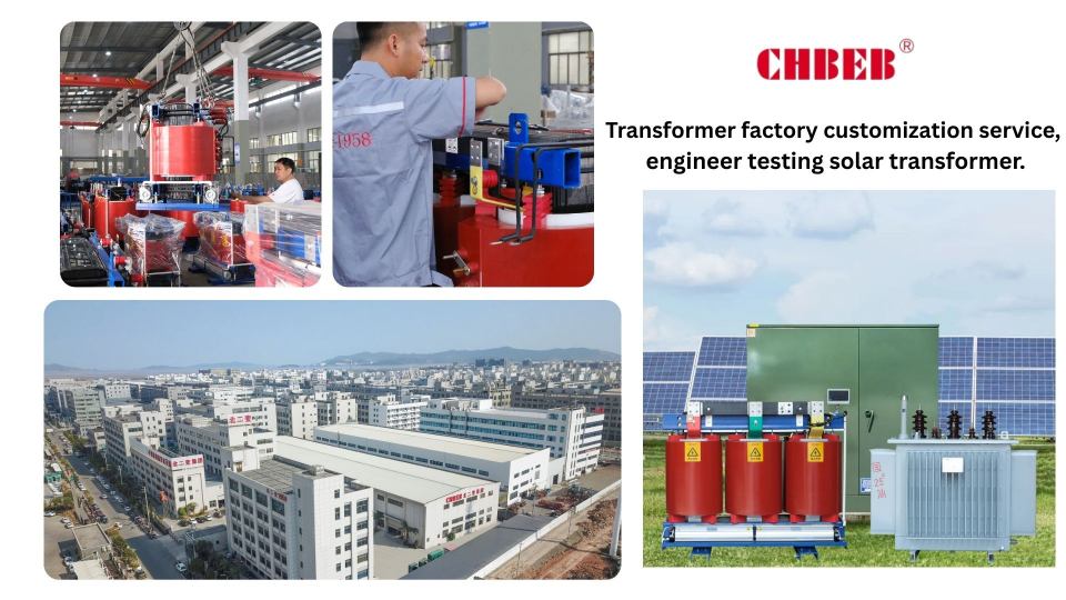
Custom Solar Transformers & Expert Support
Off-the-shelf units don’t always work in real life. Making a near-match more expensive in the long run. Set bespoke choices and rely on expert advice to keep performance, safety, and schedule on track.
Need a solution just for you?
Customize the transformer to fit your grid code, environment, and maintenance plan. The appropriate choices can pay for themselves by lowering losses, fewer outages, and a smoother commissioning process.
- Electrical: K-factor/thermal allowance for harmonics, tap range, vector group, %Z selection, and the procedure for neutral and grounding.
- Thermal and fluids: ONAN/ONAF stages, temperature-rise class, mineral or natural ester fluids, and dry-type fluids where liquids are not allowed.
- Low-noise cores and clamps, marine-grade coatings, sealed bushings, animal barriers, and compact pads are all examples of enclosure and siting.
- Monitoring: winding RTDs, oil level/temperature, and moisture indicators; optional digital gateways for predictive maintenance.
- Serviceability: standardized bushings and elbows, easy access to taps, spare parts kits, and test locations that are easy to find.
Get in touch with a Solar Transformer Expert
Projects can become stuck because of complicated standards and regulations about how things link. Misunderstanding leads to expensive redesigns. Before you send out the PO, a quick engineering review lowers the risk of selection, speeds up approvals, and makes sure your inventory matches your timeline.
- Free spec check against standards set by utilities and studies on protection.
- Side-by-side loss monetization for a real TCO comparison.
- Inventory match: generate a list of in-stock or quick-build options that fit your schedule.
- A commissioning playbook and spare parts suggestions to have things ready for day one.
Conclusion
To avoid delays and costly mistakes, make transformer selection simple and structured:
- Start with kVA and voltage: Make sure the transformer rating matches your inverter output and grid requirements.
- Request structured quotes: Ask suppliers to include not only price, but also losses, warranty, delivery time, and compliance with standards.
- Plan availability early: Know what is in stock, what can be quick-built, and what requires custom production to match your schedule.
- Use expert support when needed: Engineers can review vector groups, impedance, or cooling options to ensure safety and compliance.
In short: This approach ensures the solar transformer you purchase is correctly sized, reliable in operation, and delivers the lowest total cost over its lifetime.
- Solar inverter — Wikipedia ↩︎
- Transformer Vector Groups — All About Circuits ↩︎
- IEEE Transformer Standards — IEEE ↩︎
Learn More About Our Transformers
Want to explore more transformer solutions? Download our latest product catalog or browse our product categories to find the right fit for your project.
Introduction
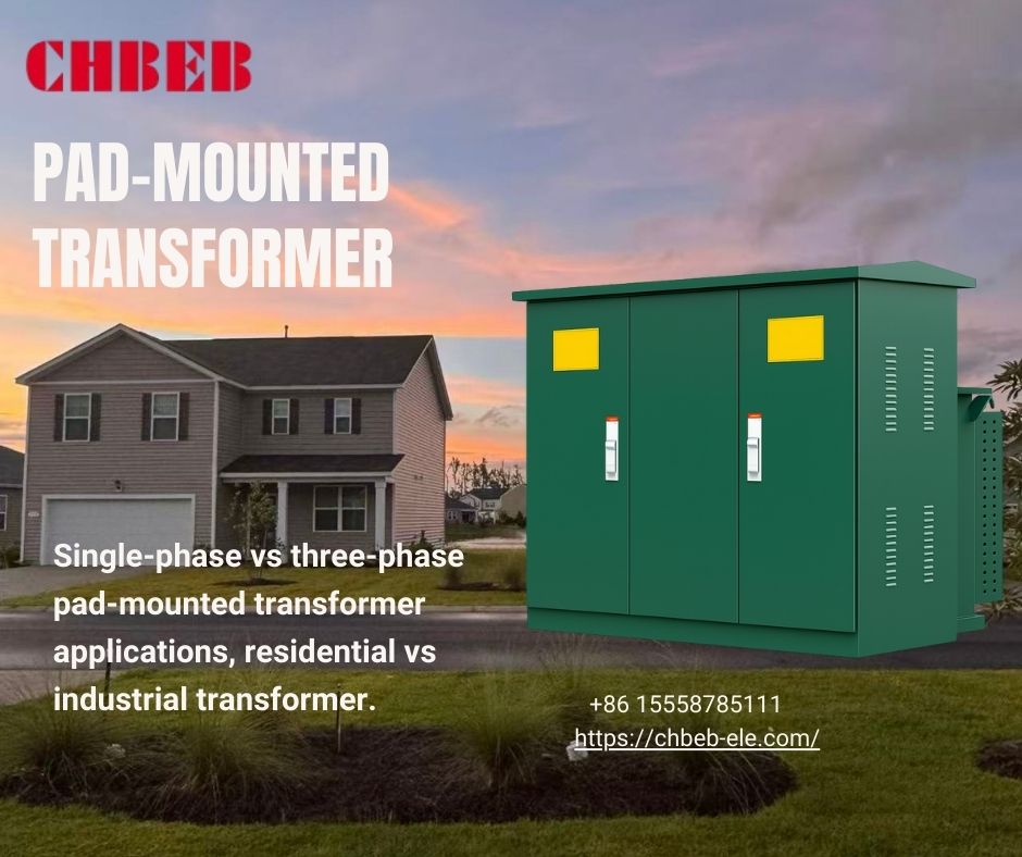
If you choose the improper phase type, you will have to deal with losses, outages, and more effort. As loads get bigger, those pains get worse. This tutorial compares three-phase and single-phase pad-mounted transformers1, explains important specs, and teaches how to use and quote them effectively.
The Core Analysis: Understanding the Key Differences for Your Project
Confusing phase types leads to downtime and wrong sizes. If you don’t keep an eye on them, budgets grow and dependability goes down. We explain the functional differences and how they affect design, protection, and O&M so you can make an informed choice for today’s loads and tomorrow’s growth.
Three-Phase vs. Single-Phase2: Which Transformer is Right for You?
The “phase” of a pad-mounted transformer decides how it sends electricity to your loads and how it works with the medium-voltage network above it. Single-phase units work best in locations with low to moderate demand, whereas three-phase units work best in places with a lot of motors, high density, or power quality issues.
| Criterion | Single-Phase Pad-Mounted | Three-Phase Pad-Mounted |
|---|---|---|
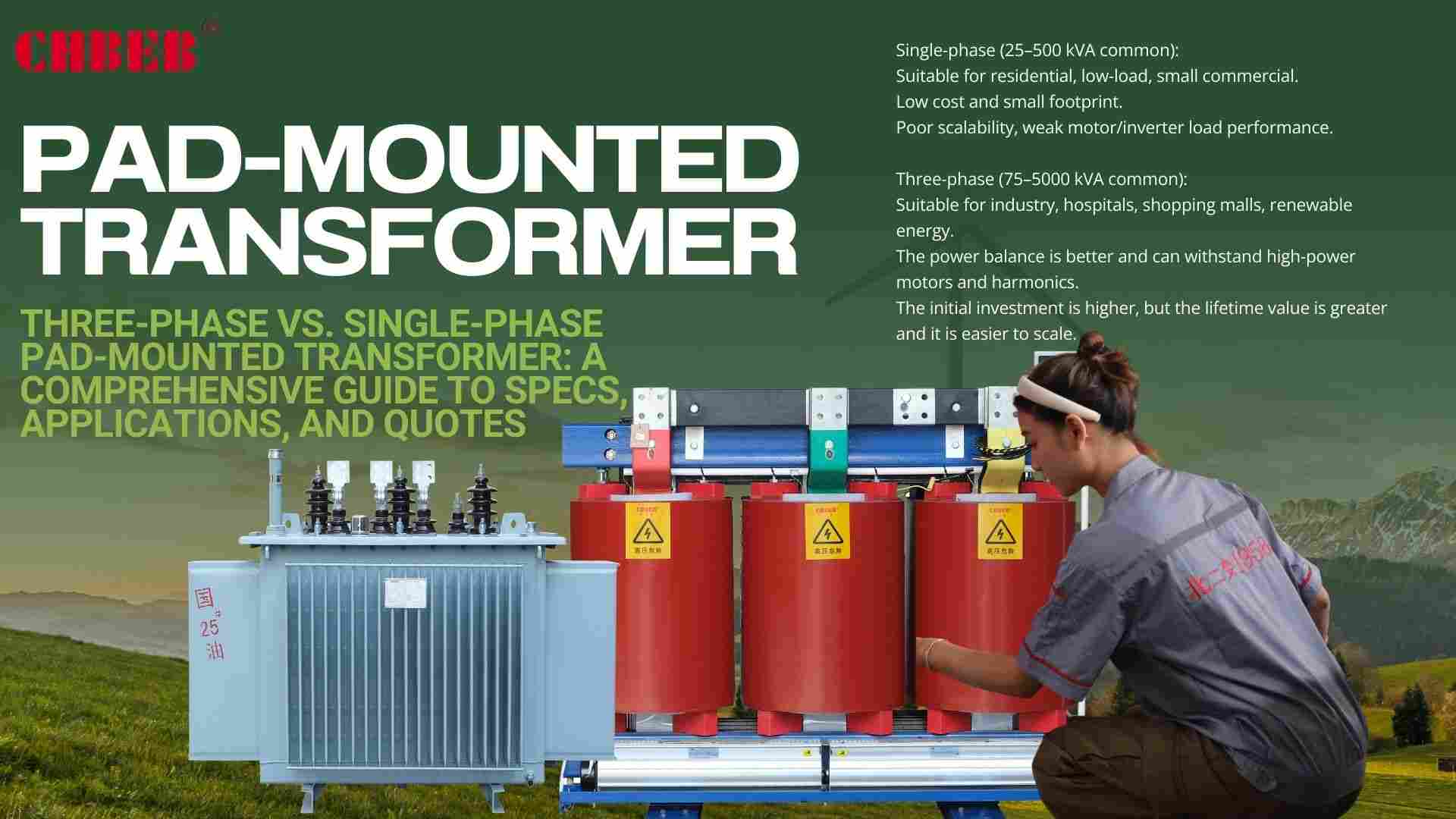
| Typical kVA | 25–500 kVA (common) | 75–5000 kVA (common) |
| Best-Fit Loads | Residential feeders, light commercial | Industrial plants, malls, campuses, renewables |
| Voltage Balance | Serves split-phase / single-phase loads | Inherently balanced for three-phase equipment |
| Motor Loads / VFDs | Limited; risk of flicker/voltage dip | Robust; better for large motors and VFDs |
| Footprint / Cost | Smaller footprint, lower initial cost | Larger, higher capex but greater capacity |
| Future Expansion | Constrained; step-ups may be needed later | Scalable; simpler to add feeders/loads |
| Power Quality | Adequate for simple, steady loads | Superior for harmonic, unbalance, and flicker control |
| Common Secondaries | 240/120 V, 480/240 V | 480/277 V, 400/230 V, 415/240 V, 208/120 V |
Three-phase often offers a higher lifecycle value in mixed-use parks or expansion corridors, even if the initial load is small. Single-phase is easier and cheaper in stable, low-density communities, as long as you think about variety and potential EV/HVAC expansion.
A Guide to Key Technical Parameters: Decoding the Specs
Specifications set the standards for safety, uptime, and operating costs. A few things that affect most results are capacity, impedance, losses, vector group, and protection. Read them as a whole, not as separate checks, and make sure they meet your utility’s criteria.
- kVA Rating: Size to peak plus expansion, which is usually 15–25%. If you make it too little, it will generate thermal stress; if you make it too big, it will increase losses.
- Primary/Secondary Voltage: Make sure the MV (for example, 11/22/33/35 kV) and the utilization voltage (for example, 480/277 V) are the same. Check the tap ranges to see whether they change with the seasons or the length of the feeder.
- % Impedance: Sets the level of fault and the voltage regulation. Too low means high fault duty or flicker, while too high means too much voltage drop.
- Vector Group3: Determines the phase shift and availability of the neutral (for example, Dyn for 4-wire secondaries). Affects how harmonics work and how grounding works.
- Losses (No-Load / Load): Guaranteed watts are directly related to energy costs and heat, which you can use to make TCO decisions.
- ONAN/ONAF stages set the thermal headroom for cooling and temperature rise. In hot or high-altitude places, use derating or extra fans.
- BIL and surge coordination: Make sure the insulation level matches the arrester MCOV and the projected switching surges on the feeder.
- Dead-front elbows, bayonet and current-limiting fuses, fault indicators, and MV surge arresters are all examples of terminations and protection.
- Sound Level: When near homes or workplaces, use low-noise cores and clamps to avoid complaints.
How to Use It and How to Buy It
Using the wrong topology costs money and could get you in trouble. If you don’t pay attention, rework and callbacks will pile up. This part shows you how to get the correct transformer at the right price by mapping out typical use cases and then walking you through scoping, customizing, and bidding.
Common Uses: When Pad-Mounted Transformers Are Necessary
Pad-mounted transformers work best in places where safety, access, and looks are important. Their lockable cabinets, dead-front terminations, and small pads make it possible to put them in public areas while yet providing utility-grade protection and ease of maintenance.
- Residential Subdivisions: Single-phase units provide quiet and safe service to neighborhoods. Plan for EV charging and heat-pump use.
- Three-phase provides different daytime peaks, escalators, HVAC, kitchens, and IT loads with balanced voltage in commercial centers and campuses.
- Hospitals and other facilities near data centers can offer more reliable vital services without needing massive substations thanks to redundancy and loop-feed possibilities.
- Three-phase withstands motor starters, welders, and VFD harmonics in industrial sites. Copper windings and strong impedance should be used.
- Renewables (PV/Wind) Blocks: Three-phase units combine inverter/generator output with MV collection systems in the right vector groups.
- Public Venues and Transit: Designs that are quiet and guard against corrosion (C4/C5-M) work well in cities and on the coast.
Getting a Quote and Customization: The Way to a Personalized Solution
A generic BOM doesn’t always fit perfectly. Not doing scoping and options leads to gear that doesn’t fit, hot areas, and change orders. A disciplined quote package makes sure that you follow the rules, know the pricing, and get your order on time.
What Should Be in Your RFQ
- Load Data: peak/diversified kVA, duty cycle, presence of motor/VFD, harmonic limitations, and growth prediction.
- Electrical Spec: MV/LV voltages, vector group, %Z target, tap range, grounding method, BIL, and sound limitations.
- Environment: ambient/altitude, corrosion category, animal guards, ingress protection, and footprint limits.
- Protection and Terminations: dead-front elbows rating, fusing system, surge arrester class, and fault indicators.
- Compliance and Tests: relevant IEC/IEEE standards, regular, type, and special tests, and documentation deliverables.
- Logistics and Schedule: the date the ship needs to leave, the weight limitations for lifting, the details of the pad, how to get to the delivery, the guarantee, and the spare parts.
Customization Options That Often Pay Off
- Loss Packages: Lower assured losses lower the cost of energy over a lifetime and the temperature of the cabinets.
- Cooling Upgrades: ONAF stages and RTDs keep hotspots stable in hot or congested settings.
- Material Choices: Copper windings for strength against heat; aluminum for loads that aren’t too heavy and don’t cost too much.
- Noise Reduction: Low-flux-density cores and dampening near homes or hospitals.
- Corrosion systems include marine-grade coatings and sealed bushings in coastal and arid areas.
- Loop-Feed Cabinets: For campuses that need to stay up, they can transition between sections and alternate sources.
Looking at Quotes Beyond the Price Tag
Turn predicted availability and assured losses into cash. When you factor in the cost of electricity, the danger of downtime, and maintenance, two “equal” bids can be tens of thousands of dollars apart over 20 years.
Basic TCO4: Capex + Civil/Installation + Energy Losses + Maintenance + Downtime Risk − Residual Value
Conclusion
Choosing a pad-mounted transformer is not only about single-phase or three-phase. The right choice means it fits your load, is safe to use, and won’t create hidden costs later.
Single-phase works well for homes and small communities.
Three-phase is better for factories, hospitals, and solar or wind projects.
Oil-filled units are cheaper and strong outdoors; dry-type is safer indoors or where fire risk matters.
Always check the basic specs: kVA size, voltage, and losses. Don’t just look at price — think about energy costs, service, and warranty.
In short: the right transformer is the one that matches your project, is safe, and keeps costs low over time.
- Pad-mounted transformer — Wikipedia ↩︎
- Single-Phase vs. Three-Phase Power — All About Circuits ↩︎
- Transformer Vector Groups — All About Circuits ↩︎
- Total Cost of Ownership — Schneider Electric ↩︎
Learn More About Our Transformers
Want to explore more transformer solutions? Download our latest product catalog or browse our product categories to find the right fit for your project.
Introduction
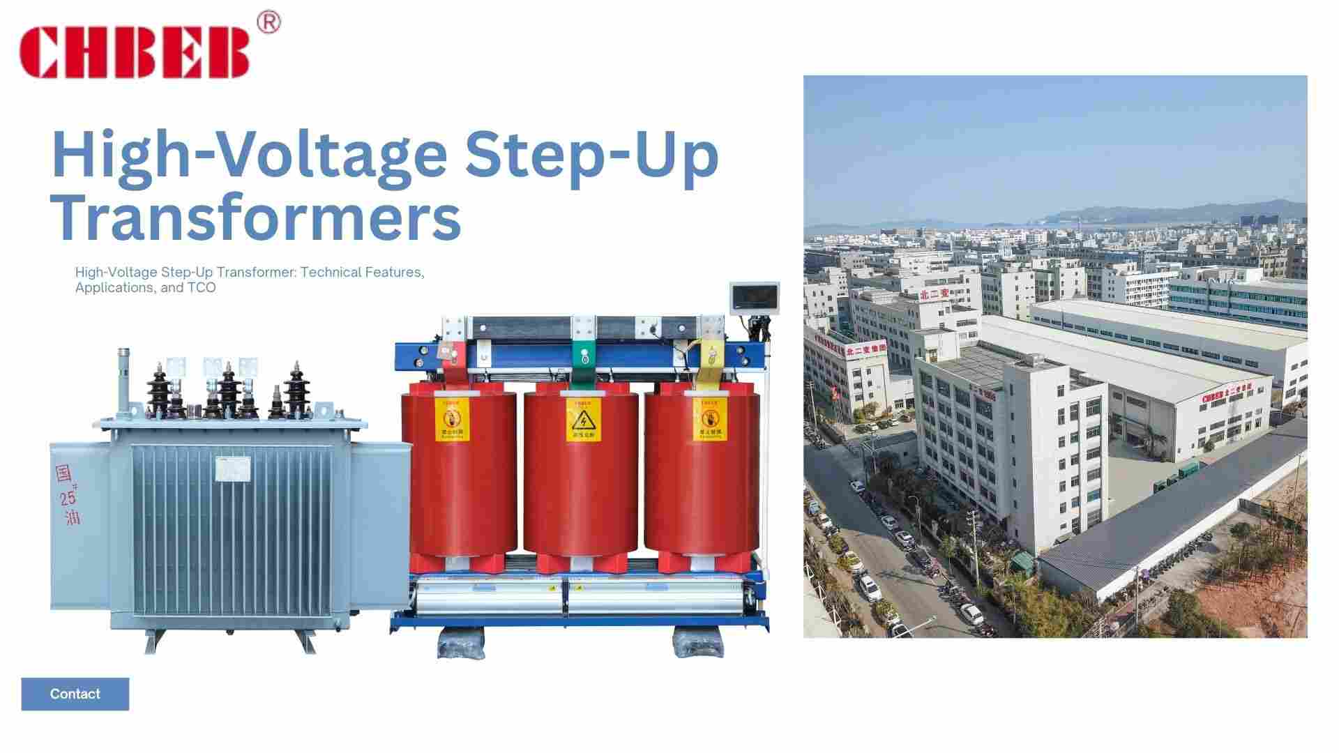
When step-up transformers1 are used incorrectly or not enough, projects run the danger of being inefficient and getting fines. These issues cause downtime, instability, and further losses. For energy projects, a high-voltage step-up transformer makes sure that connections are safe, performance is stable, and the lifecycle value is maximized.
The Product Core: A Summary and Important Technical Features
Ignoring important technical details might cause transformers to not fit together, work less efficiently, and be dangerous. Buyers may make sure that the design meets project needs and is reliable and compliant by knowing what the product’s purpose and limits are.
Product Introduction: Why a High-Voltage Step-Up Transformer Is Necessary
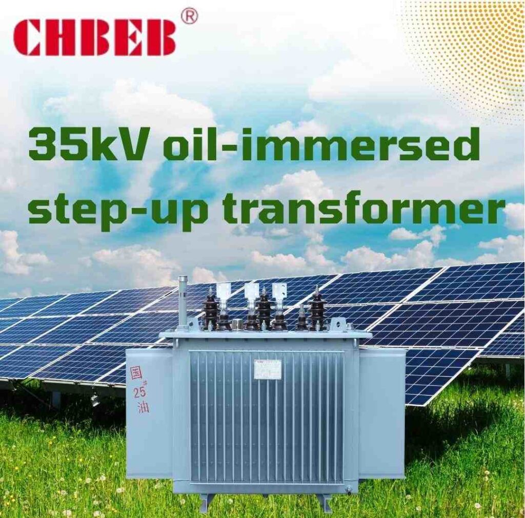
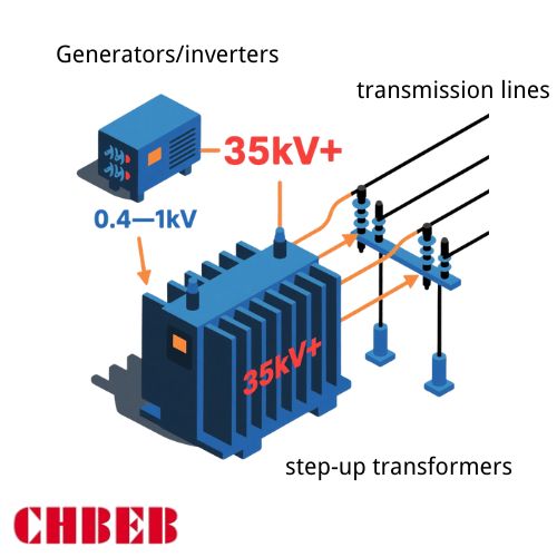
Most of the time, generators and inverters make low or medium voltage that can’t be sent. A high-voltage step-up transformer elevates this to 35 kV or more, keeps the voltage stable, and makes sure that the system meets utility regulations.
- Voltage elevation: Changes the outputs of LV/MV generators into HV levels so they can be sent more quickly.
- Isolation: Keeps source circuits separate from the utility, which keeps everyone safe and makes it easier to fix problems.
- System stability: It controls harmonics, helps with protective schemes, and keeps the grid balanced.
A Look at the Specs: Knowing the Value of Important Parameters
If you don’t pay attention to the main criteria, you could end up paying too much or not doing enough. Taking into account the most important parameters ensures a well-designed product, fewer losses, and a long service life.
- Power rating (kVA/MVA): This must match the peak load and growing margin.
- Primary and secondary voltage: Make sure the generator output meets utility HV standards (11–35kV+).
- Vector group2: This tells you how to handle harmonics, phase shift, and neutral availability.
- Impedance (%Z)3: This controls the levels of faults and the voltage.
- Cooling class: The ONAN/ONAF settings set the temperature rise and how long the product will last.
- Losses (no-load/load): Directly affect operating costs over the course of decades.
- BIL (Basic Insulation Level)4 protects against surges and switching occurrences.
How We Make Sure Your Project Is a Success with Applications and Services
When transformers aren’t matched to the right applications or aren’t supported after delivery, projects fail. We make sure that every project meets its performance and financial goals by using the correct application knowledge, cost analysis, and service.
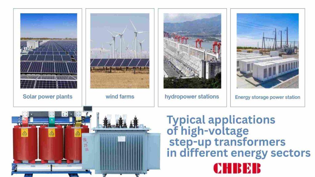
Common Uses: Where Our Products Are Very Important
High-voltage step-up transformers are very important in many fields. Using something wrong can make it less efficient and reliable, but using it correctly can make it safer and more reliable.
- Step inverter or generator outputs up to HV for transmission in utility-scale solar and wind.
- Industrial cogeneration: Safely connects CHP units to networks with medium to high voltage.
- Hydropower and thermal plants: Raise the voltage efficiently for grid export.
- Battery energy storage: lets HV systems send power in both directions.
Looking at more than just the price: using Total Cost of Ownership (TCO)5 to assess an investment
When you buy based on pricing alone, you risk hidden expenses like larger losses and downtime. Calculating the total cost of ownership makes sure that things will be useful and profitable in the long run.
TCO = Capital Expenditures + Installation + Losses + Maintenance + Downtime − Residual Value
- Energy losses: Monetize guaranteed no-load/load losses throughout 20 years of operation.
- Better designs mean less frequent inspections and lower costs for spare parts.
- Risk of downtime: Reliable units don’t go down, which can offset savings made up front.
- Residual value: Quality transformers keep their worth when they are sold or used again.
Customization and Service: Our Expert Solution for Your Project
Every project has its own needs, and not customizing can lead to a bad fit. We change designs and offer lifecycle support to make sure success with experienced engineering and timely service.
- Flexibility in design: Adjust winding material, impedance, and vector groups to fit the needs of the project.
- Adapting to the environment: Solutions for deserts, coastal areas, or high elevations.
- Service throughout the lifecycle: from testing and installing at the factory to monitoring and maintenance help.
- Quick help: Teams that respond quickly make sure that projects don’t have to stop for long.

Conclusion
Reliable grid integration depends on selecting the right high-voltage step-up transformer—not only by reading the nameplate, but by verifying what’s inside. Buyers secure safe, efficient, and future-ready outcomes when they combine technical fit, lifecycle economics, and supplier transparency.
What to do to get it right
- Match the specs: Align voltage ratio, kVA/MVA, impedance (%Z), vector group and tap range with project and utility requirements.
- Evaluate TCO: Compare no-load/load losses, expected maintenance, and downtime risk—not just upfront price.
- Verify the build quality: Require factory routine/type test reports, allow FAT (factory acceptance tests), and use third-party inspections where needed to prevent hidden compromises.
- Lock in reliability: Specify warranty terms, response SLAs, and a critical spares list (fans, bushings, gaskets, relays) to protect uptime.
In short: the right transformer isn’t defined by the lowest quote, but by technical compliance, lifecycle cost control, and proof of quality—ensuring the unit you buy performs exactly as promised for decades.
- Transformer — Wikipedia ↩︎
- Transformer Vector Groups — All About Circuits ↩︎
- Transformer Impedance and Fault Studies — IEEE Xplore ↩︎
- Transformer Insulation and BIL Studies — ScienceDirect ↩︎
- Total Cost of Ownership in Electrical Distribution — Schneider Electric ↩︎
Learn More About Our Transformers
Want to explore more transformer solutions? Download our latest product catalog or browse our product categories to find the right fit for your project.
Introduction
It’s not only about the specs when you choose a solar transformer brand. Choosing the wrong option can lead to less efficiency, more downtime, and not following the rules of the grid. This article compares three major companies: Eaton, Hitachi, and Daelim. It helps you find the right technology, service, and price for your project.

The Contenders: A Look at Each Manufacturer’s Lineup of Solar Transformers
The size, quality criteria, and pricing priorities of solar installations vary. If you don’t pay attention to brand strengths, you can get the wrong equipment. You can make sure that the aspects of your project match the technical and strategic needs of each manufacturer by knowing what they provide.
How Eaton, the Power Management Giant, Uses Solar
Eaton puts solar transformers1 into a big system for managing power. Its portfolio focuses on dependable medium-voltage step-up units, harmonics control, and compatibility with balance-of-system gear including switchgear and protection relays.
- Strengths: works with electrical distribution networks, has a proven track record, and is available in many places throughout the world.
- Uses: commercial solar, hybrid plants on a large scale, and projects that necessitate tight electrical integration.
- Focus: Safety, following the rules of the grid, and using designs that have been shown to work.

Hitachi Energy: The Best Company in the World for Grid-Scale Solutions
Hitachi Energy (previously ABB Power Grids) wants to be the best choice for large solar and hybrid renewable energy projects. Its transformers are built to be very reliable, have extensive monitoring, and function well with big transmission networks.
- Strengths: Ready to form a grid, high efficiency, and advanced digital monitoring.
- Uses: Utility-scale PV and interconnection terminals for big renewable installations.
- Focus: Long life, support for the grid, and meeting IEC/IEEE standards around the world.
Daelim: The Provider That Grows Quickly and Puts Customers First
Daelim is a dynamic company that makes solar transformers that may be customized and are affordable. It focuses on meeting the needs of EPCs and developers that need solutions that can change and speedier delivery times without sacrificing quality.
- Pros: Prices that are competitive, opportunities for personalization, and customer service that is quick to respond.
- Uses: mid-sized commercial solar farms, fast-track EPC projects, and markets for exporting.
- Focus: Finding a balance between being affordable and following the rules.

A Technical and Strategic Comparison Side by Side
When you only focus at price, you miss important distinctions in design, service, and long-term cost. A comprehensive side-by-side examination shows where Eaton, Hitachi, and Daelim differ in terms of strategy and technology.
Harmonics, efficiency, and unique features are the technical differences.
Technical details decide how well something works and how compliant it is. If you don’t understand things correctly, you could lose energy or get in trouble. Each brand focuses on different capabilities in terms of design innovation, efficiency, and managing harmonics.
- Eaton: Focus on designing safe enclosures, dead-front terminations, and reliable harmonics performance.
- Hitachi: Advanced monitoring, better insulating systems, and a high K-factor tolerance for non-linear PV loads.
- Daelim offers flexible vector group options, competitive efficiency guarantees, and loss packages that are made just for you.
Value Proposition and Market Focus: What Each Brand Does Best
Choosing without making sure that the brand focus matches the project’s needs can raise costs or lower ROI. Each manufacturer has a different value proposition.
| Brand | Value Proposition | Market Focus |
|---|---|---|
| Eaton2 | Integration, reliability, strong after-sales network. | Commercial & industrial solar with complex distribution needs. |
| Hitachi Energy3 | Premium efficiency, monitoring, grid support readiness. | Utility-scale and grid-interactive renewable projects worldwide. |
| Daelim | Cost-effective, customizable, fast delivery. | Mid-scale EPC projects, emerging export markets. |
A Look at Support, Sustainability, and TCO Beyond the Product
Service, sustainability, and running costs are what make something worth buying. Ignoring these things makes things more risky and expensive.
- Eaton has a wide range of services, high safety requirements, and reasonable efforts to be more environmentally friendly.
- Hitachi: advanced remote monitoring, a significant focus on ESG, lengthy warranties, substantial initial capital expenditures, and low operating costs.
- Daelim: quick support, competitive warranties, a growing focus on sustainability, and good prices up front.
Conclusion
Eaton, Hitachi, and Daelim each play an important role in the solar transformer market:
- Eaton: Trusted worldwide for reliable medium-voltage step-up units and strong integration with electrical distribution systems.
- Hitachi Energy: Recognized as a premium provider for utility-scale and grid-interactive projects, with high efficiency and advanced digital monitoring.
- Daelim4: Known for competitive pricing, customization flexibility, and responsive service, making it a strong choice for mid-scale EPC projects.
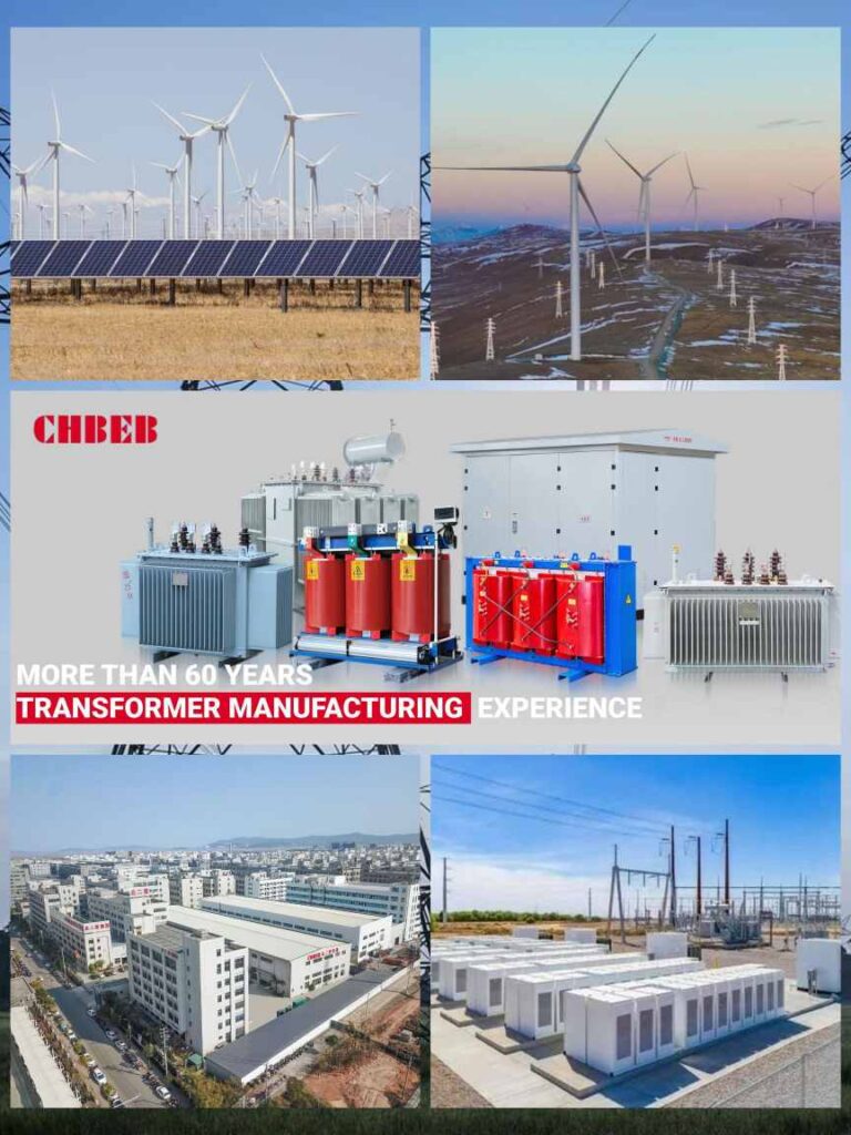
Alongside these global brands, CHBEB POWER (Beierbian Group Co., Ltd.) offers another perspective as a factory-direct manufacturer with 60+ years of experience. With production bases in Wenzhou and Nanjing and an office in Beijing, CHBEB supplies oil-immersed transformers, dry-type transformers, pad-mounted substations, and special application transformers that meet IEC, ANSI, ISO9001/14001/45001 standards.
As a qualified supplier to the State Grid of China and an experienced exporter to Southeast Asia, the Middle East, Africa, Russia, and Latin America, CHBEB emphasizes OEM/ODM customization, fast R&D and delivery (7–15 days for standard products), and proven international project performance.
In short: Each manufacturer brings unique strengths. For project developers and EPCs, the best choice depends on project size, technical requirements, budget, and delivery expectations. By comparing established global players with factory-direct suppliers like CHBEB, buyers can find the solution that best balances quality, compliance, cost, and schedule for their solar and renewable projects.
- Solar inverter — Wikipedia ↩︎
- Eaton — Eaton Corporation ↩︎
- Hitachi Energy — Hitachi Energy ↩︎
- Daelim Transformer — Daelim Electric ↩︎
Learn More About Our Transformers
Want to explore more transformer solutions? Download our latest product catalog or browse our product categories to find the right fit for your project.
Introduction
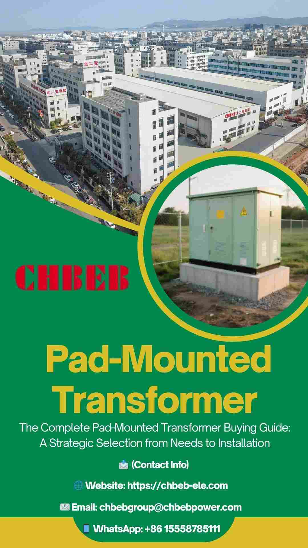
Buying just based on price doesn’t work. Outages and penalties happen when ratings are inaccurate, the wrong sort of feed is used, or the improper materials are used. This article takes you through every step, from figuring out what you need to installing your pad-mounted transformer1, so that it is safe, reliable, and costs the least during its lifespan.
Phase 1: Strategic Planning and Needs Assessment
Planning without enough information leads to overloads, voltage drops, and noise complaints. These problems come up after the system is turned on, when repairs are costly. Set the right capacity, voltage, and design for your site by defining loads, duty, and growth immediately.
How to Figure Out Your Project’s Power and Load Needs
Don’t use a vendor template; start with the electrical reality of your site. Find out how much the transformer needs to supply now and in three to five years, and then use that information to make judgments on its nameplate and configuration.
- Demand profile: Find the peak kW/kVA, daily and seasonal diversity, and coincidence factors. Include a reasonable growth margin, which is usually between 15% and 25%.
- Load character: Keep track of motor starters, VFDs, EV charges, HVAC cycling, and non-linear loads that cause harmonic heating and voltage changes.
- Check the ratings of the secondary (e.g., 400/230 V, 415/240 V, 480/277 V, or 208/120 V) and service entry gear to be sure they can handle the voltage.
- Power quality goals: Set the facility and utility’s acceptable levels of voltage regulation, flicker, and harmonic distortion.
- Reliability goals: Make sure you know how long the system needs to be up, how long it can be down for maintenance, and if maintenance can be done without an outage.
Understanding the Two Main Types: Loop-Feed and Radial2
Picking the wrong primary configuration makes you more likely to have an outage or costs you more money. Choose a feed type that meets your needs for stability and future growth.
| Primary Configuration | How It Works | Strengths | Watch Outs | Best For |
|---|---|---|---|---|
| Radial | Single MV source feeds the transformer directly. | Lowest equipment cost; simple protection and operation. | Any upstream fault/outage drops the load; limited switching flexibility. | Small commercial sites, low criticality loads, constrained budgets. |
| Loop-Feed | Two MV cables form a loop with load-break switching in the cabinet. | Alternate source improves availability; sectionalizing enables maintenance without full outage. | Higher capex; requires trained operators and coordination with the utility. | Campuses, hospitals, retail parks, data-heavy sites, future expansions. |
For loop systems, make sure there are dead-front load-break elbows, clear labels, and interlocks so that only authorized staff can safely switch them.
Phase 2: Decoding Technical Specifications and Features
Often, copying specs from one project to another doesn’t work. Mismatch causes losses, flickering, and annoying trips. Pay attention to the few statistics and features that affect safety, compliance, and durability at your site.
Key Technical Specs: The Most Important Numbers
The nameplate condenses performance into a few key numbers. Learn these things so you don’t spend too much for capacity or too little for reliability.

- kVA rating: Size to meet peak demand and growth. Oversizing makes losses worse, whereas undersizing shortens life through thermal stress.
- Voltage for primary and secondary: Match the utility MV (for example, 11/22/33/35 kV) and the voltage you use (for example, 480/277 V). Check the transformer taps.
- % Impedance: Keeps the current and voltage in balance. If the fault responsibilities are too low, they will be too high; if they are too high, the voltage loss will be too high during peaks.
- Vector group3: Figure out the phase shift and the availability of the neutral (for example, Dyn for 4-wire secondaries). Changes how harmonics are handled and how grounding works.
- BIL (insulation level): Work with surge arresters and the projected switching surges on MV feeders.
- Losses (no-load/load): Guaranteed watts turn immediately into operational costs; use them to compare TCO.
- Thermal headroom and dependability are defined by the ONAN/ONAF stages and the temperature rise.
- Sound level: Very important near homes and businesses; if needed, list low-noise solutions.
- Dead-front is standard for public safety when it comes to terminations. Check the type of bushing and the elbow rating.
- Inside the cabinet, there are fault indicators, current-limiting fuses, and MV surge arresters to protect the bayonet.
| Parameter | What It Affects | Buyer Checklist |
|---|---|---|
| kVA | Thermal margin, lifespan | Peak + 15–25% growth; duty factor accounted |
| %Z | Fault level, regulation | Coordinate with breakers and flicker limits |
| Losses | Opex, heat | Price losses at your tariff for TCO |
| BIL | Surge withstand | Match arrester MCOV and feeder exposure |
Material and Design: Transformers that are immersed in oil vs. those that are dry
Choosing the wrong construction makes things more risky and expensive. Make sure the dielectric and enclosure are right for fire safety, the environment, and maintenance.
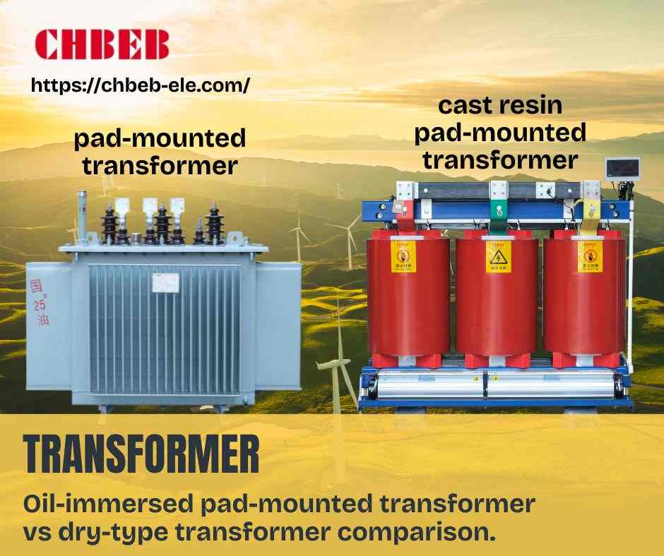
- Oil-immersed (mineral or natural ester): This is the most frequent type of pad-mounted design. High thermal capacity, small size, and proven outdoors. Natural esters4 make the fire point and biodegradability higher, which makes it easier to get safety and environmental permits.
- Dry-type (cast resin/VPI): Good for places where liquids are not allowed or for use indoors. Bigger, usually more expensive per kVA, and more sensitive to dust and humidity. Make sure the enclosure has enough protection from the outside and enough airflow.
- For coastal and desert areas, make sure to include corrosion protection (such C4/C5-M), wildlife guards, sealed bushings, and low-noise laminations.
- Serviceability: Choose designs that have easy access to the taps, standard bushings and elbows, gaskets that can be replaced, and spare parts that are easy to find.
Phase 3: The Long-Term View: Cost, Safety, and Maintenance
The lowest bid is not always the lowest cost. If you don’t pay attention to safety and maintenance, you could have downtime and be responsible for damages. Look at lifetime losses, dependability, and serviceability now to keep availability and ROI high for decades.
Looking at Total Cost of Ownership (TCO) Beyond the Price Tag
When comparing transformers, look at more than simply capex; also look at losses and availability. Use the same formula for all bids.
TCO = Capital Expenditures + Civil/Installation + Energy Losses + Maintenance + Risk of Downtime − Residual Value
- Figure out how much the losses cost: Annual cost ≈ (No-load kW + Load-loss kW × Load2) × 8760 × tariff. Over 20 years, even modest disparities in loss add up.
- Availability value: Loop-feed, superior cooling, and strong protection cut down on downtime, which is typically worth more than little capital expenses reductions.
- Safety and compliance: Dead-front terminations, interlocks, and the right BIL/arrester coupling lower the cost of incidents and the amount of insurance coverage needed.
- Serviceability: Spare kits, standardized parts, and front access make maintenance and repairs faster and easier.
When bids are close, turn assured loss values and projected downtime into dollars. The “cheapest” unit isn’t always the least expensive to own.
Installation and upkeep: the best ways to make sure things last a long time
Even the best equipment will break down if it isn’t installed properly or checked on time. You can’t change civil works, bonding, or frequent testing.
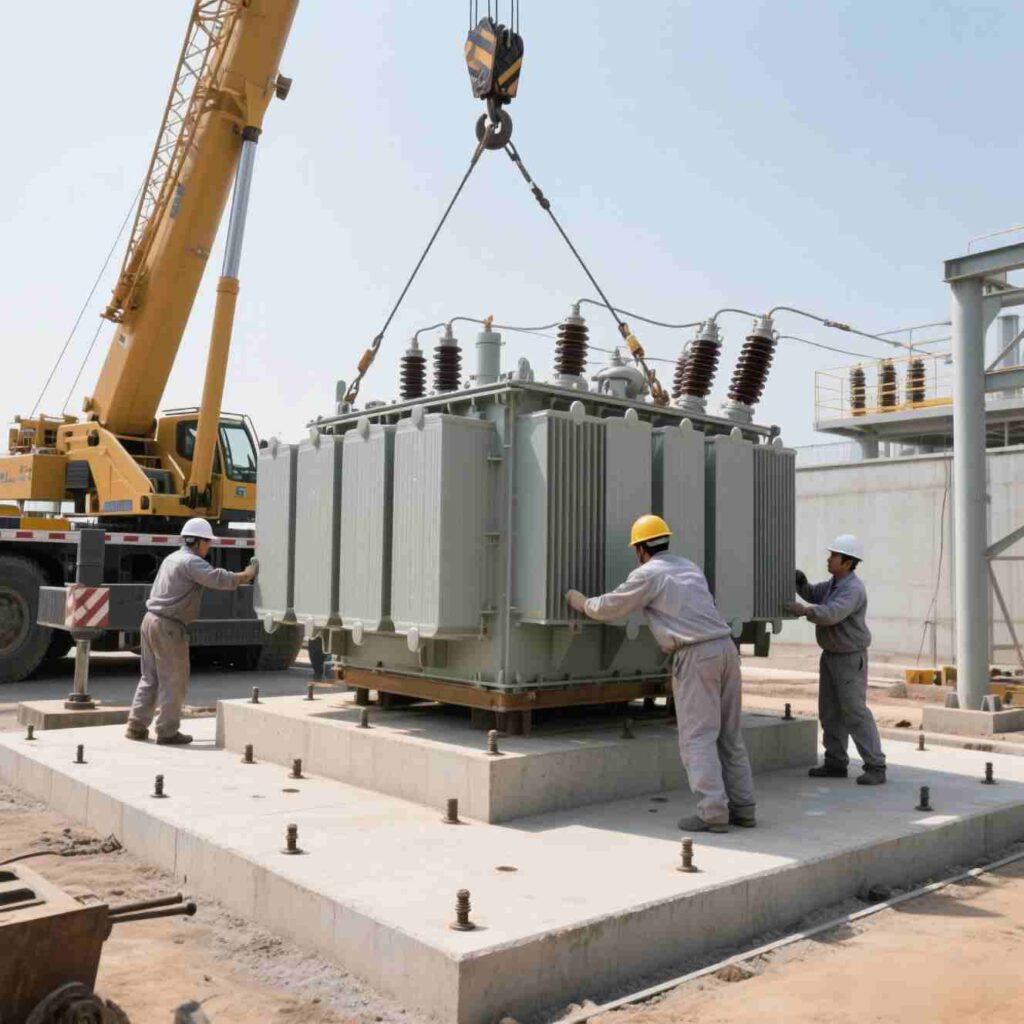
Things You Need for Installation
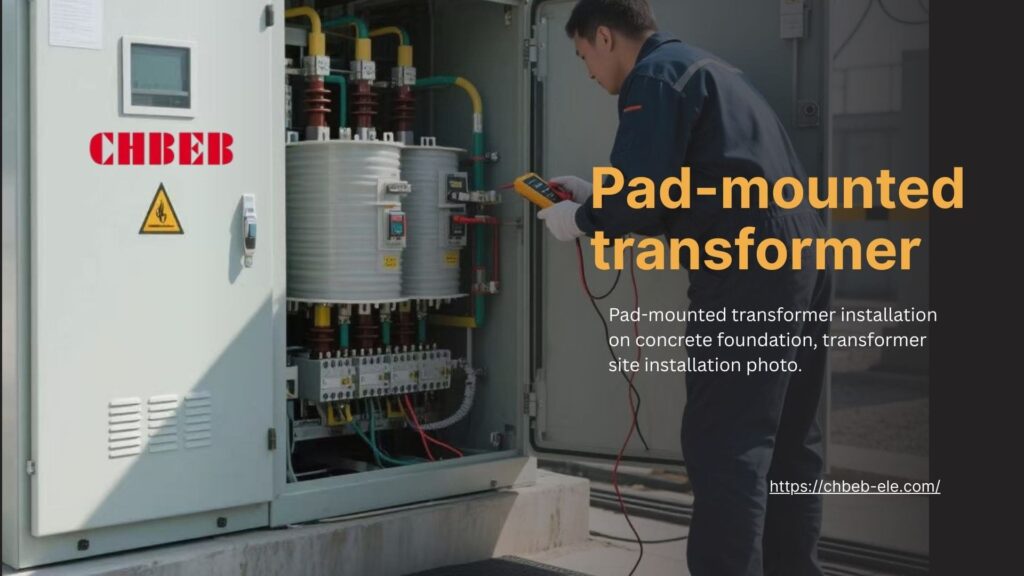
- Pad and placement: A level, load-rated concrete pad with drainage away from the cabinet. Make sure there is enough space for working and ventilation.
- Grounding and bonding: Connect all metal parts; check that the ground resistance targets are fulfilled; run the earthing conductors in a short, direct path.
- Terminations: Use the right dead-front elbows, follow the bend radii, torque to spec, check the phasing and tap settings, and make sure everything is labeled clearly.
- Checks before commissioning: insulation tests, checking the ratio/phase angle, fan operation (if ONAF), alarm setpoints, and the condition of the arrester.
Maintenance Essentials
- Regular checks: seals, gaskets, paint, hinges, animal protection; clean the vents and radiators in the cabinets.
- Electrical health: Keep an eye on the trend in load and temperature, and do infrared scans every so often to find hot connections early.
- Units filled with liquid: Check the pressure relief devices and gauges; take oil samples to check for moisture and dielectric strength.
- Records and spares: Keep track of alarms and trips, and keep a spare kit (elbows, gaskets, fans, relays) on hand to speed up repairs.
Conclusion
Pad-mounted transformers are not simply oil-filled or dry-type units—they are a complete, metal-enclosed outdoor solution engineered for modern distribution networks where public safety, compact footprint, and underground cabling are essential. Installed directly on a concrete pad with a sealed, lockable cabinet, they avoid the need for separate rooms, fencing, or ad-hoc protections common with conventional units.
Why choose pad-mounted instead of “just oil or dry”
- Safety & compliance: Dead-front terminations, tamper-proof enclosure, and interlocks improve public safety and code compliance.
- Compact & aesthetic: Small footprint and clean streetscape—ideal for campuses, communities, and commercial parks.
- Underground integration: Designed for underground MV/LV cable entry, switching, and sectionalizing in one package.
- Flexible dielectric: Can be built as oil-immersed (mineral or natural ester) or dry-type—the enclosure and features remain pad-mounted.
Buyer takeaway: think beyond upfront price
- TCO control: Pad-mounted designs often reduce civil works, safety add-ons, and long-term downtime risk.
- Fit to environment: Specify coatings, cooling stages, and noise targets for desert, coastal, or community sites.
- Right spec, fewer surprises: Match kVA, %Z, vector group, and tap range to utility requirements and future growth.
In short: Choosing a pad-mounted transformer isn’t just buying a device—it’s securing safe, code-compliant, low-maintenance power distribution that fits today’s urban and industrial environments, while keeping lifetime costs under control.
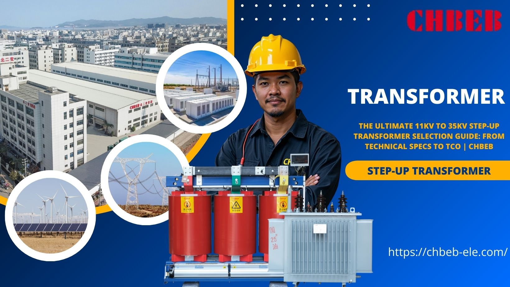
Introduction
When step-up transformers1 are the wrong size or kind, projects fail. The outcome is tripping, overheating, and not following the rules. A well-designed 11–35 kV step-up transformer raises voltage, isolates faults, and stabilizes power quality. This makes it safe to connect, increases availability, and lowers the lifetime cost.
Technical Core: What 11kV to 35kV Step-Up Transformers Do and What Their Key Parameters Are
Copying and pasting LV specs doesn’t take into account the realities of step-up. Some of the effects are voltage drops, heat stress, and protection miscoordination. Learn how 11–35 kV step-up transformers function and which nameplate numbers are really important for safety, compliance, and efficiency. This can help you avoid costly redesigns and downtime.
Why go up? How transformers are essential to energy projects
Most generators and inverters make low- or medium-voltage electricity that is not very good at traveling long distances. A step-up transformer raises the voltage (for example, from 0.4–1.0 kV to 11–35 kV), offers galvanic isolation, sets the grounding scheme, shapes fault levels, and filters triplen harmonics by choosing a vector group2. This makes connections stable, efficient, and safe.
- PV and wind: Increase the output of the inverter or generator to 22/33/35 kV collection or export feeders while keeping an eye on harmonics and DC bias concerns.
- CHP / industrial export: Make sure that process loads and grid tie-ins can be isolated, have their voltage controlled, and have a neutral connection.
- Battery storage: Allow electricity to flow in both directions and have thermal margins that are good for charge/discharge cycling.
Without the right step-up design, projects are more likely to lose money, have flickering lights, nuisance visits, and fail to meet grid code, all of which quickly eat away at ROI.
Reading the Nameplate: The Four Most Important Technical Details You Need to Know
The nameplate gives a few important values that sum up how the transformer works. Mastering these stops mistakes in specifications and speeds up approvals.
- 1) Duty and power rating (kVA/MVA): Size for continuous export with a realistic load profile. Variable renewables need thermal headroom for ramps, clipping technique, and the flexibility to handle inverter overload. If you make anything too little, it will overheat. If you make it too big, it will lose money on both the load and the no-load, as well as on capital expenditures.
- 2) Voltage ratio and vector group: Set the LV/HV ratios so they match the source and the grid. Vector groups, like Dyn11 and YNd11, decide how to handle phase shift, triplen harmonics, and the availability of neutral. Make sure your protection studies and the utility’s earthing approach are in line with each other.
- 3) Impedance (%Z) and BIL: %Z controls the current and voltage of a fault. If the yield is too low, there are a lot of faults and flickers. If it is too high, the drop under ramps is too high. Basic Insulation Level has to work with surge arresters and switching surge exposure on feeders that carry 11–35 kV.
- 4) Cooling, temperature rise, and losses: ONAN/ONAF stages, the maximum temperature rise allowed, and the promise of no-load/load losses all affect dependability and opex. If the site is hot or at a high altitude, lower the rating or add forced-air phases. Think about using natural ester fluids if you want a higher fire point and better performance in the environment.
| Parameter | What It Affects | Buyer Checklist |
|---|---|---|
| kVA/MVA rating | Thermal headroom, lifespan | Use peak export + margin; include ramps and duty cycle |
| Voltage & vector group | Grounding, harmonics, phase shift | Match utility spec; confirm neutral and earthing |
| %Z & BIL3 | Fault levels, voltage regulation, surge withstand | Coordinate with breakers, arresters, and feeder studies |
| Cooling & losses | Efficiency, hotspots, opex | Check guaranteed losses; verify ambient/altitude allowances |
A Practical Guide: Things to Think About When Choosing, Keeping, and Analyzing Total Costs
Buying based only on price might lead to hidden energy losses, service interruptions, and fines. A structured approach—using the correct type, the right environment, and the proper controls—lowers risk and operating costs. To get the best total cost of ownership and reliable output, use the checklist below to choose, install, and keep up with.
How to Choose Based on Project Needs: Types, Environment, and Customization
Start with the application and duty cycle, and then make sure that the electrical, mechanical, and environmental needs are all met. Before you order, check your assumptions with a study of protection and power quality.
- Application and duty: PV and wind need thermal headroom for ramps, and industrial drives may need to be able to handle larger short-time overloads.
- Type & dielectric: Oil-immersed (mineral or natural ester) is the most common type used outside. Esters make the fire point higher and the biodegradability better. Dry-type suits are better for interior locations where liquids can’t get in, but they cost more and cool down differently.
- Voltage and taps: Set LV to the source (for example, 0.48/0.69/0.8–1.0 kV) and HV to the grid (for example, 11/22/33/35 kV). Off-circuit taps, like ±2 × 2.5%, aid with seasonal or feeder-length changes. OLTC is rare at this rating, but it can be used on weak or lengthy lines.
- Impedance and parallel operation: Set %Z to work with upstream devices and flicker restrictions. To manage circulating current in parallel units, set the %Z and vector group to the same value.
- Vector group and grounding: Pick a delta or star orientation to block triplens and make a stable neutral when needed (solid, high-resistance, or resonant earthing).
- Environment: List the temperature class, altitude derating, corrosion category (for example, C4/C5-M), sand/salt ingress control, animal guards, and acoustic targets that are close to communities.
- Mechanical and footprint: Make sure there is enough room for terminations, fans, and tap access. Check the weight and size of the transport and the pad loading.
- Protection and monitoring: Surge arresters, PRV/RPRR, oil level/temp gauges or winding RTDs, fan control, and optional digital sensors (moisture, hotspot) make predictive maintenance possible.
- Documentation and tests: Ask for regular test reports; for important units, ask for type or custom tests. Make sure that the tolerances for loss and impedance match what you think they should be in your study.
| Scenario | Design Focus | Why It Matters |
|---|---|---|
| Utility-scale PV on long feeders | Higher %Z, wider taps, low losses | Stabilizes voltage along feeders and cuts feeder losses |
| Onshore wind farm | Thermal headroom, arresters, corrosion control | Handles gust-driven ramps and harsh coastal climates |
| Industrial cogeneration | Vector group/grounding, noise control | Protects sensitive loads and meets acoustic limits |
| Battery storage (bi-directional) | Symmetrical thermal design, monitoring | Supports charge/discharge cycling without overheating |
More than just price: figuring out long-term value by looking at the total cost of ownership (TCO)
The lowest offer might cost the most to own. To compare options fairly, turn guaranteed loss values and expected availability into cash.
TCO = Capex + Installation/Civil + Energy Losses + Maintenance + Downtime/Risk − Residual Value
- Energy losses: No-load losses happen all the time, while load losses go up with load2. To figure out how much they cost, multiply (kW) by the number of hours in a year and the tariff.
- Value of availability: A single day of curtailment might erase years of “savings” from a unit that costs less and runs hotter.
- Cooling strategy: More ONAF fans cost more upfront, but they lower the temperature of hotspots, which makes insulation last longer and lowers the danger of failure.
- Choosing a fluid: Natural esters might lower the cost of fire safety and environmental liability. Please include numbers for these offsets.
- Serviceability: Standardized bushings, front access, clear tap indication, and replacement parts all make outages shorter and labor costs lower.
- Warranty and supplier strength: Longer warranties and test data that has been confirmed to work reduce the risk of ownership. Give them dollar weight in comparisons.
Tip: When bids are close, make money off the losses and downtime that you expect. The transformer with the “lowest price” isn’t always the cheapest to own.
Installation and Maintenance Basics: How to Keep Things Running Smoothly
Even the best equipment can break down if it isn’t installed correctly or is not checked on regularly. You can’t change civil works, bonds, terminations, or monitoring.
Installation
- Civil and placement: a level, load-rated pad with drainage away from the plinth; keep ventilation and working space clear.
- Grounding and bonding: Connect all metal parts; make sure the arrester MCOV/BIL matches the feeder surge levels; keep the earthing lines short and straight.
- Terminations: Follow the bend radii; torque to spec; check the phase rotation and vector group; write down the tap position and baseline temperatures.
- Commissioning: Check the insulation (IR/tan δ if necessary), the fans, the alarm setpoints, and the protection coordination.
Maintenance
- Operational monitoring: Use IR scans to find connection hot spots early on, and keep an eye on trend load, winding hotspot, and ambient.
- For liquid-filled units, take a sample of the oil to check for moisture and condition. Also, examine the cleanliness of the PRV/RPRR, gauges, gaskets, and radiator.
- Check the enclosure filters, clean the ducts, and make sure the RTDs and fans are working.
- Spares and records: Keep a set of gaskets, fans, relays, elbows, and bushings that match; write down alarms, trips, and interventions so you can find the root cause quickly.
Conclusion
Step-up transformers in the 11–35 kV range are more than nameplate ratings—they are the gateway that lets your project export power safely, legally, and profitably. Unlike distribution transformers that step voltage down for end users, a step-up unit boosts low generator/inverter voltages to grid levels so transmission is efficient and stable.
What this means for buyers
- Losses drive real money: No-load and load losses become electricity bills over decades. Ask for guaranteed loss values and annualize them.
- Uptime protects revenue: Warranties, critical spares, and service commitment reduce unplanned downtime and curtailment risk.
- Fit to environment: Specify coatings, cooling stages, and derating for desert heat, coastal corrosion, altitude, and acoustic limits.
How to control TCO in practice
- Request data, not just price: Include guaranteed no-load/load losses, temperature rise, and ONAN/ONAF stages in bids, and convert losses (kW) × hours × tariff → yearly cost.
- Contract for reliability: Compare warranty length, response SLAs, and a spares list (fans, gaskets, bushings, relays). Treat uptime value as cash in evaluations.
- Match application: Align vector group, %Z, and tap range with grid studies (fault levels, flicker, grounding). Avoid “one-spec-fits-all.”
- Plan the site: Require pad loading/footprint confirmation, clear termination access, and documented commissioning (IR/tan δ if needed).
- Prove compliance: Ask for routine test reports to IEC/IEEE; for critical units, add type/special tests and loss tolerances.
In short: selecting the right 11–35 kV step-up transformer isn’t only about passing grid approval. It’s about turning every kilowatt-hour into long-term revenue by controlling losses, safeguarding uptime, and specifying the right design for your environment and duty—so your project delivers stable output at the lowest lifetime cost.
The Solar Transformer Guide: Unlocking the Technical Core from PV Array to Grid
Introduction
Transformers that don’t match, run hot, or change the quality of the power make PV plants work less well. If not fixed, losses, trips, and fines will happen. A solar transformer separates1, boosts, and controls the output of an inverter so that solar energy can safely and efficiently connect to the grid.
The “Heart” of the PV System: The Main Job and Technical Problems of Solar Transformers
PV sites have to deal with limited space, changing output, and rigorous constraints about how to connect to other systems. Not paying attention to these causes problems and failures. Solar transformers made for this purpose create a safe, compliant connection between string/central inverters and the utility network, managing voltage and harmonics where they are most important.
What is a Solar Transformer? The Important Part It Plays in the Photovoltaic System
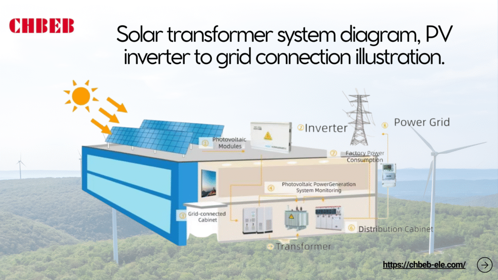
The solar transformer is the electrical “heart” that changes the output of a low-voltage inverter into medium-voltage levels for collection or export. It does this while making sure that everything is safe, works with other devices, and is reliable. It does more than just modify the voltage; it also has functions that are specific to how PV works:
- Galvanic isolation: This keeps the inverter circuits separate from the utility, which makes it possible to safely find and fix faults.
- Step-up conversion: This raises the normal outputs of inverters (about 400–1000 VAC) to MV feeders (about 11–35 kV) so that they can be sent more efficiently within the plant and to the grid.
- Vector group and zero-sequence control: Delta and star selections stop triplen harmonics, control neutral currents, and help with grounding schemes.
- DC bias tolerance: This stops leftover DC from inverters from causing core saturation and overheating.
- Impedance tuning: Changes the shape of fault currents and voltage regulation, keeping the collecting system stable during ramps and failures.
- Environmental resilience: Outdoor-rated enclosures, protection against corrosion, and classes for temperature rise that work in deserts, on the shore, or in the mountains.
- Integration: MV switchgear, protection, and metering are all in the same place in skid or power-station designs, which makes them easier to set up.
A Closer Look at the Two Technical Problems of Voltage and Harmonics
The output of the PV changes and has switching artifacts. If not handled, voltage swings and harmonics can lower yield and break grid codes. Solar transformers deal with both of them by making choices about taps, impedance, vector group, and thermal margins.
- Managing voltage: The inverter AC goes up and down with the amount of sunlight and the temperature. Set the right tap ranges (like ±2×2.5%) to keep the MV at the point of connections. OLTC isn’t prevalent in PV, but it can make sense for long feeders or weak grids.
- Ride-through and regulation: Make sure that the transformer’s impedance can handle low- and high-voltage ride-through without too much voltage drop when power ramps up quickly.
- Risk of DC injection: Even little DC parts can make the core flux reach saturation. Set DC tolerance and monitoring; make sure that the inverter’s DC-injection restrictions are followed.
- Harmonic control2: Multilevel switching lowers THD, although high-frequency parts increase stray losses. Use the shape of the winding, the shielding, and the location of the core and winding to keep the heating to a minimum.
- Vector group strategy: A delta on the inverter side can catch triplen harmonics and smooth out the currents that the MV system sees. A star on the MV side gives neutral/earthing where needed.
- To avoid resonance, think about cable capacitance and how filters interact with each other. Choose %Z and layout to keep amplification away from switching frequencies.
- PWM ripple can cause audible noise, which is called acoustic noise. Low-noise designs, clamping, and controlling flux density help keep complaints down near communities.
Practical Application: Choosing, Designing, and Future Trends
Bad ratings, bad cooling, or old specs waste money and energy. That hurts LCOE and compliance over time. Use a strict selection procedure and up-to-date monitoring to make sure you design things well now and are ready for what tomorrow will bring.
How to Pick the Best Solar Transformer: Important Factors and Design Issues
Make the specification based on measured demand, environmental stresses, and grid rules. Then check the thermal and electrical margins for PV’s heavy-duty ramp. Check out the list below.
- Power rating (kVA/MVA): The size of the inverter should be enough to handle the peak AC power and any growth or dirt that may occur.
- Primary and secondary voltages: Make sure that the inverter AC (for example, 480/690/800–1000 V) matches the collection/export MV (for example, 11/22/33 kV) and utility standards.
- Impedance (%Z)3: Set restrictions on the fault current, keep the voltage steady, and let several transformers work together on the same bus.
- Vector group: Dyn or Ynd variations are common alternatives for PV. Check with the utility to make sure the neutral and grounding approach is correct.
- Losses and efficiency: Look at the no-load/load losses over the predicted dispatch profile. Low losses lower the lifetime energy cost and heat.
- Cooling and insulation: ONAN/ONAF for most outdoor work; for greater fire point and sustainability, think about natural ester fluids, or dry-type fluids where liquids are not allowed.
- Thermal class and ambient: Give the temperature rise and the ambient temperature (for example, 40–50 °C in the desert) as well as the altitude derating. If necessary, include forced-air stages.
- DC tolerance and harmonics: Set limits for DC bias, K-factor, or an equivalent thermal allowance, and devise ways to deal with high-frequency ripple.
- Taps and regulation: Off-circuit taps are common. Only use OLTC if the greater complexity and maintenance are worth the extra voltage control value.
- Environment and corrosion: Coatings for C4/C5-M maritime and industrial environments, animal guards, sand shields, and IP/ingress protection that fit the site.
- Monitoring and protection: oil level and temperature (or winding RTDs), pressure relief, quick pressure rise, moisture indicators, and bushing or partial-discharge options.
- Standards and testing: Follow the IEC4/IEEE rules that apply; ask for routine test reports and, for important units, type/special tests.
| PV Scenario | Design Focus | Why It Matters |
|---|---|---|
| String inverters on long MV feeders | Higher %Z, wider taps, low-loss core | Stabilizes voltage along feeders; reduces feeder losses. |
| Central inverter block near substation | Compact footprint, high thermal margin | Handles concentrated heat; eases layout and maintenance. |
| Weak grid interconnection | Careful impedance, OLTC evaluation, robust vector group | Improves ride-through and voltage compliance under disturbances. |
| Desert/coastal environment | C5-M coatings, sand/salt ingress control, ester fluids | Extends service life, enhances fire safety and sustainability. |
| Hybrid PV + storage (bidirectional) | Bi-directional thermal design, dc-bias limits, monitoring | Supports charge/discharge cycling without overheating or saturation. |
How Solar Transformer Technology Has Changed Over Time to Make Your System Future-Proof
PV systems are scaling and digitizing. Designs that fit today may constrain tomorrow’s output or compliance. Build with headroom and adopt technologies that track where PV is going, not where it was.
- Higher DC bus and inverter power: 1500 Vdc arrays and higher-power blocks push transformer currents and thermal design. This means that there are large temperature rise margins and staged cooling.
- Materials and fluids: Amorphous cores reduce no-load losses. Natural esters enhance the fire point and biodegradability while also making the material more resistant to moisture.
- Digital monitoring: Online indications for temperature, humidity, and dissolved gas (where they apply) make it possible to plan maintenance ahead of time and cut down on downtime.
- Designing for good power quality: Advanced winding and shielding shapes cut down on stray losses caused by inverter switching. Vector groups are tailored to reduce harmonics.
- Hybrid and grid-forming readiness: Storage and grid-support functions add bidirectional flows and new fault characteristics; make sure that thermal and dielectric symmetry is maintained.
- Control of EMI and sound: Low-noise laminations, better clamping, and EMI shielding keep neighboring communities and sensitive equipment safe.
- Harsh-site packaging: IP ratings that are higher, sealed bushings, barriers for wildlife, and corrosion systems that are meant to last for decades, not just seasons.
- Modular power stations: Factory-installed transformer and MV switchgear skids cut down on schedules, make quality more consistent, and make O&M easier.
Conclusion
Solar transformers are not just ordinary transformers placed in PV plants — they are purpose-built to bridge the gap between the low-voltage output of inverters and the medium/high-voltage levels required by the utility grid.
Unlike conventional distribution transformers that step voltage down for end users, a solar transformer primarily works as a step-up device: it boosts a few hundred volts from PV inverters to 11 kV, 22 kV, or 33 kV for safe, efficient interconnection.
Why step-up is essential
- Reduces current for a given power level.
- Minimizes I2R line losses and cable heating.
- Enables reliable collection and delivery over distance to the grid POI.
PV-specific challenges a solar transformer must handle
- Voltage fluctuation: rapid ramps with irradiance and temperature.
- Harmonics & high-frequency ripple: from inverter PWM switching.
- DC injection risk: preventing core saturation and protection trips.
- Harsh environments: desert heat, coastal corrosion, wildlife ingress.
Design responses that ensure safety & cost control
- Appropriate impedance (%Z) and tap ranges for voltage stability and ride-through.
- Optimized vector group (e.g., Dyn/Ynd) for triplen-harmonic trapping and grounding strategy.
- Winding/core geometry and shielding to limit stray losses and acoustic noise.
- Thermal headroom with ONAN/ONAF cooling; options for natural esters or dry-type where required.
- Monitoring (winding/oil temperature, pressure relief, moisture/PD options) to reduce unplanned outages.
In short: choosing the right solar transformer is not just about “making the connection.” It is about ensuring stable transmission, reducing losses, protecting equipment, and aligning technology, safety, and environment with your project’s future growth.
- Solar inverter — Wikipedia ↩︎
- Harmonics in Power Systems — IEEE Xplore ↩︎
- Transformer Impedance and Fault Current — ScienceDirect ↩︎
- IEC Transformer Standards — IEC ↩︎
Learn More
Want to explore more transformer solutions? Download our latest product catalog or browse our product categories to find the right solution for your project.
Introduction
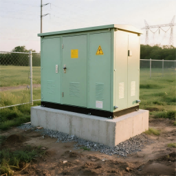
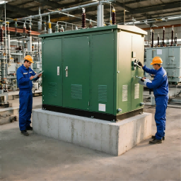
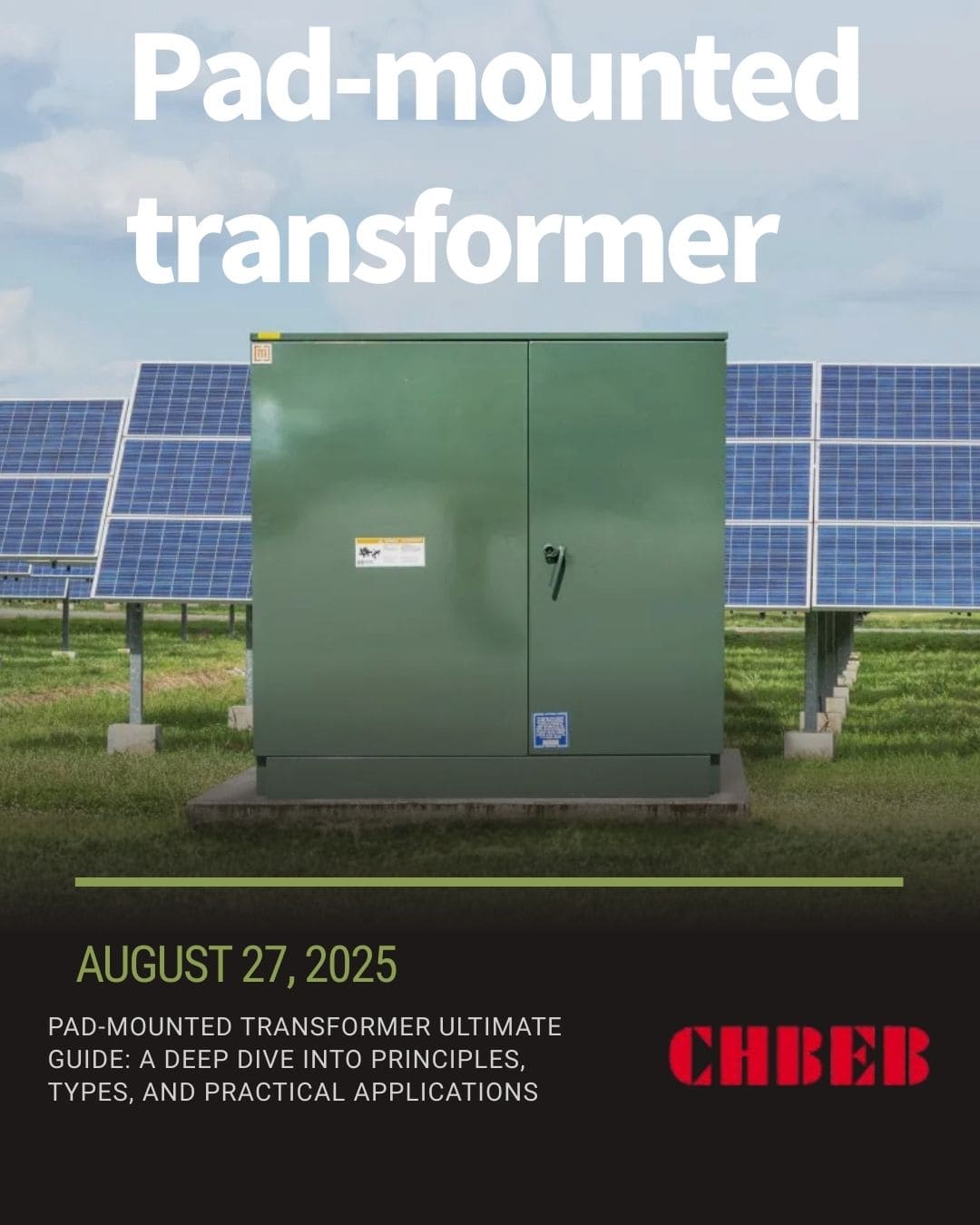
Transformers that are hazardous, old, or too big often cause problems with power distribution. These problems lead to excessive costs, dangers, and downtime. Pad-mounted transformers1 overcome these problems by providing safe casings, a small design, and easy integration into the ground.
In-Depth Analysis: Core Principles and Advantages of Pad-Mounted Transformers
A lot of projects have trouble with big substation designs, not enough space, and keeping the public safe. Utilities could have outages and accidents if they don’t find better alternatives. Pad-mounted transformers overcome this problem by being safe, easy to install, and able to work with underground cables.
What is a transformer that is mounted on a pad? What Sets Them Apart from Regular Transformers
A pad-mounted transformer is a distribution transformer that is on the ground and is protected by a metal cabinet. It connects to underground wires and doesn’t need any extra barriers, unlike devices that are installed on poles or fences. This makes it perfect for homes, businesses, and cities where safety and looks are important.
- Put right on the ground on a concrete pad.
- The lockable cabinet keeps people safe from electrical dangers.
- Works with underground distribution systems.2
- Needs less land and infrastructure than regular substations.
Three main reasons to choose a pad-mounted transformer
Choosing the improper transformer might cause overloads, safety problems, or extra expenditures. Pad-mounted transformers get around these problems by having features that make them more reliable and easier to use.
- Safety: Tamper-proof enclosures keep people from touching them by accident or vandalizing them.
- Efficiency: The small size of the design means less area is needed and it works reliably.
- Integration: Works perfectly with schemes for subsurface distribution and renewable energy.
A Guide to Choosing, Installing, and Taking Care of Practical Applications
Bad choices or poor maintenance can lead to downtime, risks, and having to replace things early. To avoid these problems, purchasers should pay attention to the type of transformer, the right specifications, and long-term care.
The most common types of pad-mounted transformers and where they are used
Choosing without knowing the type and use might waste money and make things work less well. Finding the proper model makes sure that it works well and is reliable in any situation.
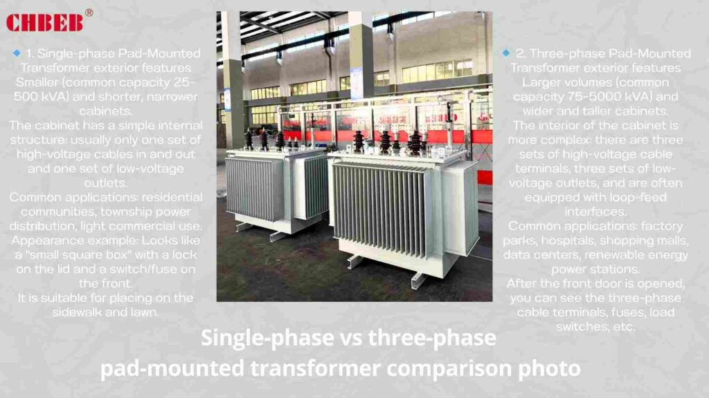
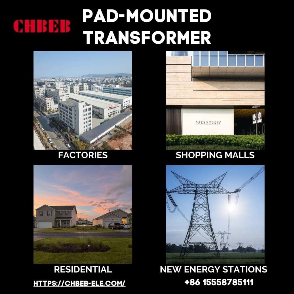
- Single-Phase3: Used by homes, small enterprises, and utilities in rural areas.
- Three-Phase: Helps industries, hospitals, shopping malls, and projects that use renewable energy.
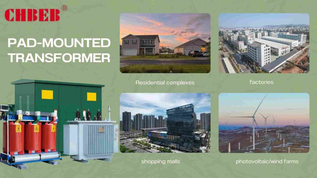
Some uses are for subdivisions, universities, shopping malls, factories, and solar or wind energy plants.
How to Choose the Right Technical Parameters for Your Needs
Costs and risks go up when ratings are too high or don’t match. Matching technical specifications to real demand keeps things from being too busy and makes sure they work well.
- Capacity (kVA): Make sure it can handle the current and future load needs.
- Voltage: Make sure it works with both the utility supply and the facility’s needs.
- Cooling: Pick either oil-immersed or dry-type based on the setting.
- Copper is strong and aluminum is cheap, so they are both good for winding4.
- Standards: Make sure that IEC5, IEEE, or local certification is up to date.
Installation and Maintenance Basics: Keeping Things Safe and Lasting
If you don’t install and care for a transformer properly, it will break down. Following important rules keeps assets safe and makes them last longer.
Advice on how to install
- Put it on a concrete platform that is solid and level.
- Keep space open for air flow and safe access for technicians.
- Make sure that ground and bond connections are correct.
How to Take Care of Your Things
- Check seals, gaskets, and bushings on a regular basis.
- Check the insulation oil or dry-type windings every so often.
- Check the load balance to keep it from getting too hot.
Conclusion
Conclusion
Pad-mounted transformers are more than just compact transformers in metal boxes — they represent a flexible solution that adapts to different environments and safety needs.
For most residential areas, industrial parks, and utility projects, oil-immersed pad-mounted transformers are the standard choice due to their reliable cooling, cost-effectiveness, and ability to handle larger capacities. On the other hand, dry-type pad-mounted transformers provide added safety and environmental protection, making them ideal for hospitals, schools, metro stations, and other places with strict fire or leakage requirements.
By understanding the internal structure (core, windings, insulation, protection devices) and matching the right type — oil or dry — to your project’s technical and safety demands, buyers can ensure long-term stability, reduced maintenance risks, and a safer power distribution system.
In short: choosing the right pad-mounted transformer is not just about installation convenience — it’s about aligning technology, safety, and environment with your project’s future growth.
- Pad-mounted transformer — Wikipedia ↩︎
- Underground Distribution Systems — IEEE Xplore ↩︎
- Transformer Basics — All About Circuits ↩︎
- Comparison of Copper and Aluminum Windings —ScienceDirect ↩︎
- IEC Transformer Standards — IEC ↩︎
Explore More Transformer Solutions
Want to learn more about our transformer products? Download the latest product catalog or browse our product categories to find the right solution for your project. 📥 Download Product Catalog 🔎 Browse Product Categories
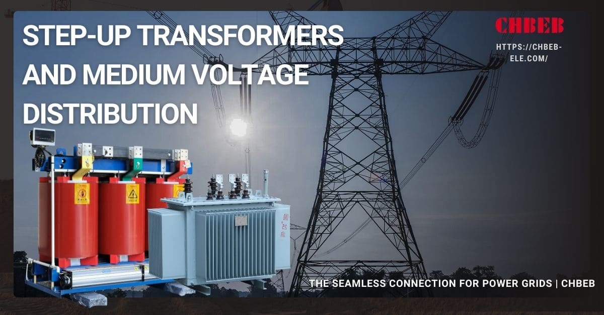
Step-Up Transformers and Medium Voltage Distribution: The Seamless Connection for Power Grids
Introduction
One of the biggest problems with power systems is getting electricity to where it has to go. If you don’t have the correct transformer approach, you lose a lot of energy, expenses go up, and reliability goes down. Step-up transformers and medium voltage (MV) distribution work well together to fix this problem. Let’s find out how they are connected in current power systems.
I. Why should you step up? Understanding the Main Purpose of Step-Up Transformers
Problem: Moving a lot of power at low voltage consumes energy. Agitate: Losses grow with current, making the grid’s economics worse. Step-up transformers raise voltage and lower current, which cuts down on line losses and makes transmission cheaper.
The Science of Stepping Up: Why More Voltage Means Less Loss
The formula for conduction losses on a line is Ploss = I²R1. When the voltage goes up, the current goes down for a given power: P = V × I. If you double the voltage, the current goes down by half and the resistive losses go down by a quarter. Step-up transformers make this high-voltage, low-current system possible so that power plants can send electricity over hundreds of kilometers without losing too much power.
- Less copper loss: Lower current cuts down on I²R heating in conductors and transformer windings.
- Thinner wires or greater spans make transmission lighter and cheaper.
- Better stability margins: Lower losses mean better voltage profiles and more room for heat.
Quick lens: 220 kV lines carry around 10 times less current than 220 kV lines with the same megawatt flow.
How Step-Up Transformers Work and What They Are Used For
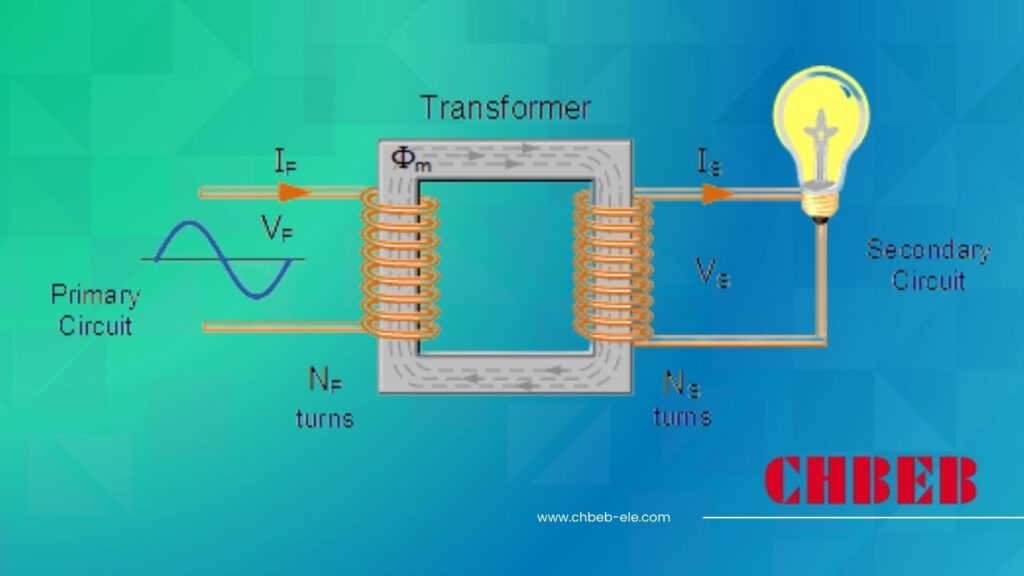
A step-up transformer has more secondary turns than primary turns, which employs electromagnetic induction to enhance the secondary voltage. The apparent power stays about the same (minus losses) even when the voltage goes up and the current goes down. The goal is simple: provide a lot of electricity across long distances at a low cost, and then reduce it near loads.
- The MVA rating, primary and secondary voltage, vector group, impedance, short-circuit withstand, BIL, cooling (ONAN/ONAF/ODAF), tap-changer type (on-load/off-circuit), and standards (IEC/IEEE) are all important features that purchasers look at.
- Levers of reliability include the core material, the winding design, the insulation class, the management of partial discharge, and the monitoring of the oil and winding temperatures.
II. The Grid’s “Last Mile”: From High Voltage Transmission to MV Distribution
Problem: Facilities can’t use or safely work with extra-high voltage. Power is meaningless and harmful without the correct step-down. MV distribution connects transmission to local networks, transmitting power at safe voltages with protection and management.
What does “Medium Voltage Distribution” mean? Common Uses and Voltage Levels
Depending on where you are, medium voltage is usually between 1 kV and 35 kV2. It provides power to cities, campuses, factories, business districts, and utility customers through MV feeders and distribution transformers that finally drop the voltage to LV (e.g., 400/230 V) for use.
| Typical MV Level | Regions / Notes | Common Applications |
|---|---|---|
| 10–11 kV | Asia, EMEA utilities | Urban feeders, factories, hospitals, schools |
| 13.8–15 kV | North America, LATAM | Campuses, data centers, commercial districts |
| 20–22 kV | EU, Middle East | Industrial parks, municipal networks |
| 27.6 kV | Canada | Suburban feeders, long MV runs |
| 33–35 kV | Global | Regional MV backbones, renewable collection |
- MV assets: Primary substations (HV/MV), ring-main units (RMUs), reclosers, sectionalizers, capacitor banks, voltage regulators, distribution transformers, protection relays, SCADA/RTUs.
- Customer interface: Pad-mounted or unit substations that power LV switchboards and final circuits.
The MV Distribution Network’s Structure and Main Problems
MV networks can be simple and cheap, like a radial network, or more reliable, like a looped or meshed network. Today’s problems are about resilience, power quality, and combining variable renewables with electric vehicle loads without raising the risk of outages or operational costs.
- Long feeders, DER backfeed, and daytime PV peaks drive tap operations and regulator sizing for voltage regulation.
- Protection coordination: Inverter-based resources change fault currents, therefore relays need to be retuned to be more sensitive and selective.
- Harmonics, flicker, and imbalance in power quality need filters, tuning of capacitors and reactors, and management of three-phase loads.
- Reliability: FLISR (fault localization, isolation, service restoration), automation, and reclosers all help lower SAIDI/SAIFI.
- Storm hardening, undergrounding, arc-flash reduction, and condition monitoring (DGA, PD, thermal) all help with safety and resilience.
III. The synergy of step-up transformers and MV distribution from generation to consumption
Problem: It doesn’t matter how efficiently power is generated if it stops before it gets to users. Agitate: If you don’t deliver MV or if you don’t transmit it well, the chain breaks. Answer: Step-up From plant to plug, GSUs and MV networks function together as one.
Use Cases in Power Plants and Renewable Energy
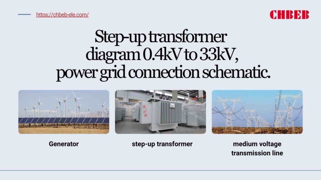
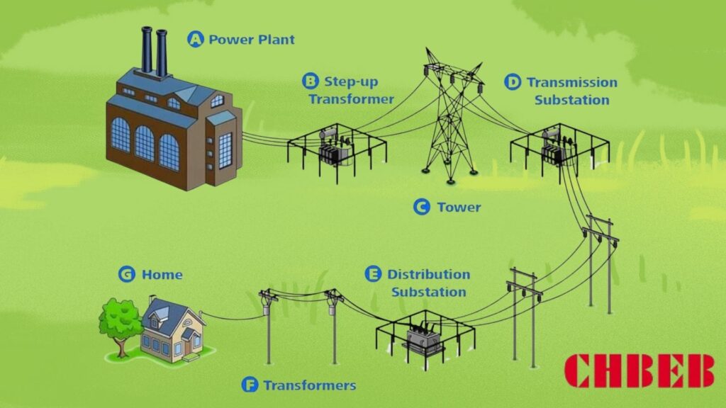
In a conventional power plant, the generator terminals are between 11 and 20 kV. A generator step-up (GSU) boosts this to 110–500 kV (or greater) so it can be sent. An HV/MV substation near load centers drops down to, say, 33 kV. MV feeders send power to districts, where distribution transformers send LV to buildings.
- Thermal and hydro: High GSU MVA values, small impedance windows, and strong cooling for continuous duty.
- The grid interface uses on-load tap changers (OLTC) and AVR to work with transmission operators to keep the voltage steady.
Wind or solar farm: The turbines and inverters put out power at LV/MV (0.69–34.5 kV). Collection step-up transformers combine outputs into a range of 66 to 220 kV for export. Downstream, MV distribution takes in renewable flows and keeps things stable by using voltage regulation, capacitor banks, and, more and more, storage.
- Collector systems: A major substation step-up connects pad-mounted transformers at each turbine/string.
- Operational focus: curtailment logic, ride-through compliance, reactive power support, and ramp-rate management.
Flow at a glance: Generator (11–20 kV) → GSU Step-Up (110–500 kV) → Transmission → HV/MV Substation (e.g., 220/33 kV) → MV Feeders (33/11 kV) → Distribution Transformers → LV Loads (400/230 V).(110–500 kV) -> Transmission → HV/MV
What will happen in the future: problems and chances in smart grids and distributed generation
Digitalization and decentralization tighten the link between step-up assets and MV operations. Expect more sensors, automation, and power electronics to enhance flexibility, reliability, and efficiency—while managing bi-directional flows and new load shapes.
- DERMS and orchestration: Distributed energy resource management solutions manage PV, wind, storage, and controllable loads across MV feeds.
- Advanced transformers: OLTC on distribution transformers, ester oils, and new solid-state ideas for faster, more precise voltage management.
- Edge intelligence: µPMUs, smart reclosers, and FLISR make things easier to see and fix themselves after problems.
- BESS and high-power chargers move peaks and offer voltage profiles for MV storage and EV fast charging.
- Condition-based maintenance: Online DGA, thermal/PD sensors, and analytics help transformers last longer and reduce downtime.
Conclusion
Step-up transformers and MV distribution work together to move a lot of energy quickly and safely. Mastering both makes your grid and projects more resilient, lowers losses, and gets them ready for a smarter, cleaner energy future.
- Power Loss in Transmission Lines, All About Circuits — ↩︎
- Medium Voltage Technical Guide, Schneider Electric — ↩︎
Learn More About CHBEB Transformers
Want to explore more transformer solutions for your project? Download our product catalog or browse our product categories to find the right fit for your needs.📥 Download Product Catalog🔎 Browse Product Categories
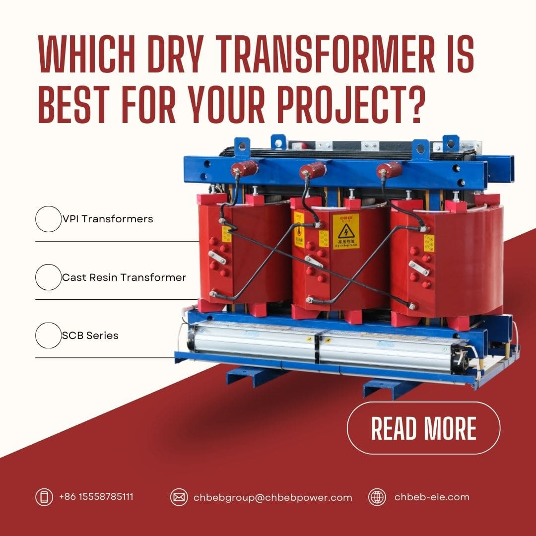
Are you having trouble deciding which dry-type transformer is best for your power distribution requirements? The abundance of choices can be daunting and may result in expensive errors. By demystifying VPI, Cast Resin, and SCB transformers, this thorough guide will enable you to choose the best option for your project.
Core Comparison: VPI vs. Cast Resin Dry-Type Transformers
Are you perplexed by the distinctions between cast resin and VPI transformers? You’re not by yourself. Many experts fail to notice important subtleties that have a big influence on project results. To help you understand your alternatives, let’s examine each type’s essential traits.
What is a VPI Transformer1?
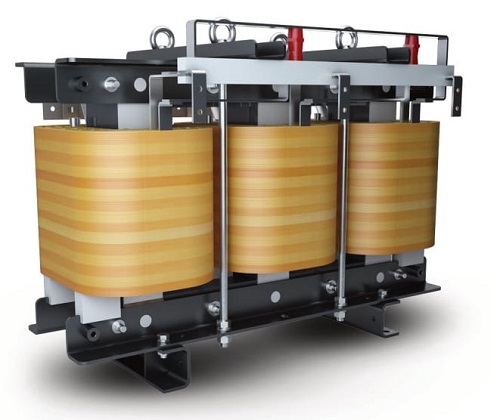
Insulating resin is applied to the windings of VPI (Vacuum Pressure Impregnation) transformers using a unique procedure. What you should know is as follows:
- Production Method:
- Insulating material is woven around the windings.
- A vacuum chamber is used to hold the assembly.
- Under pressure, epoxy resin is added and enters the windings.
- After the resin cures, a solid, void-free insulation is produced.
- Principal Benefits:
- Outstanding resistance to moisture
- High heat conductivity
- Ideal for outdoor projects that have the appropriate enclosures
- In general, less expensive than cast resin
- Restrictions:
- somewhat less fire resistant than cast resin
- After the resin cures, a solid, void-free insulation is produced.
What is a Cast Resin Transformer2?
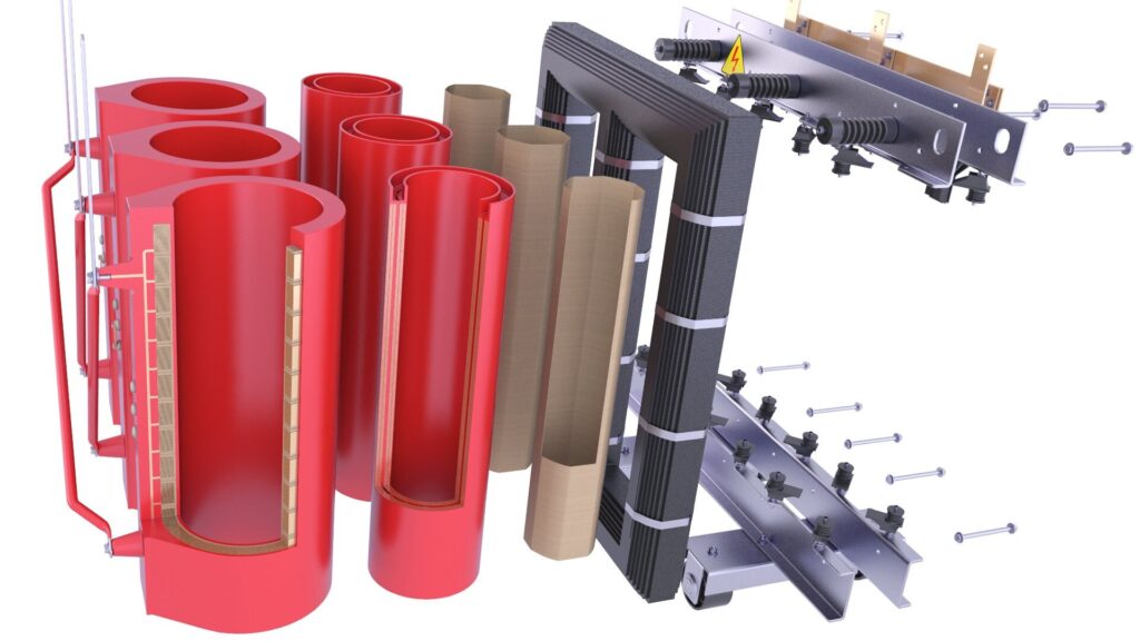
The windings of cast resin transformers, sometimes referred to as epoxy resin transformers, are covered in solid epoxy resin. What distinguishes them is this:
- Production Method:
- Molds are used to hold windings.
- Under vacuum, epoxy resin is poured into the molds.
- After curing, the resin solidifies into a block surrounding the windings.
- Principal Benefits:
- Outstanding resistance to flames
- Better defense against hostile conditions
- Low maintenance needs
- Perfect for installations indoors in congested regions
- Restrictions:
- More costly than VPI transformers in general
- heavier than their VPI equivalents
- may be limited in situations with extremely high humidity levels.
VPI vs. Cast Resin: Key Features at a Glance
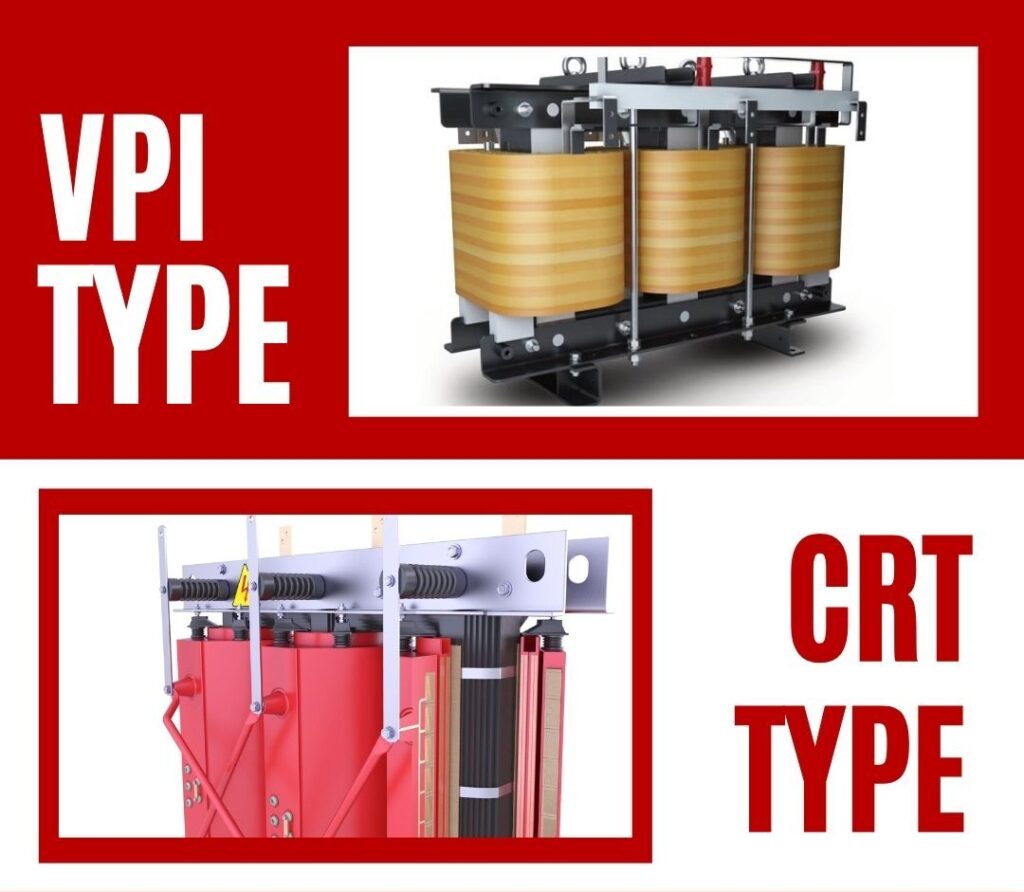
Here is a comparative table of important features to assist you in making an informed choice:
| Feature | VPI Transformer | Cast Resin Transformer |
|---|---|---|
| Insulation Method | Vacuum Pressure Impregnation | Epoxy Encapsulation |
| Fire Resistance | Good | Excellent |
| Moisture Resistance | Excellent | Very Good |
| Initial Cost | Lower | Higher |
| Maintenance | Moderate | Low |
| Weight | Lighter | Heavier |
| Outdoor Suitability | Good (with enclosure) | Excellent |
| Noise Level | Lower | Slightly Higher |
| Overload Capacity | Higher | Lower |
Clarifying the Concept and Standards for SCB Series Transformers

A particular kind of dry-type transformer that combines elements of both VPI and Cast Resin technologies is called a SCB (Shielded Cast-Resin Bushing) transformer. Important things to comprehend:
- Design:
- improves insulation by using cast resin bushings.
- VPI or Cast Resin winding technology may be used.
- Criteria:
- conforms to IEC 60076-113 for transformers of the dry type.
- fulfills particular specifications for bushing performance and design.
- Uses:
- frequently employed in commercial and industrial contexts
- It can be installed both indoors and outdoors (with the right enclosures).
- Benefits:
- Increased security as a result of protected bushings
- Enhanced dependability in demanding settings
- Adaptable design to satisfy certain project needs
How to Make the Best Choice for Your Project? A Decision Guide
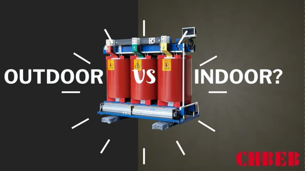
Are you having trouble deciding which kind of transformer is best for your particular requirements? You’re not by yourself. Many project managers fail to consider important aspects that could result in less than ideal performance or needless expenses. To help you make the best choices, let’s dissect the main deciding elements.
First and foremost, the project environment and safety requirements
When selecting the appropriate transformer, safety and the installation environment are crucial factors. Think about these factors:
- Comparing Outdoor and Indoor Installation
- VPI: Suitable for both, but for outside use, a suitable enclosure is needed.
- Cast resin is great indoors, particularly in crowded places, but it may also be utilized outside with the right protection.
- SCB: Adaptable to both outdoor and indoor settings
- Safety against fire4:
- VPI: Good fire resistance; extra fire safety precautions could be needed.
- Excellent fire resistance makes cast resin perfect for high-risk locations.
- SCB: Shielded bushings increase fire safety
- Conditions of the Environment:
- Humidity: High humidity improves VPI performance.
- Cast Resin and SCB provide superior protection against salt and chemical exposure.
- Temperature Extremes: Take into account each type’s unique ratings
- Rules Regarding Noise:
- In general, VPI generates less noise.
- In delicate locations, cast resin can need extra noise reduction.
Key Decision Factor 2: Budget & Total Cost of Ownership
Although the initial cost is significant, it is imperative to take into account the transformer’s total cost of ownership (TCO)5 over its lifetime:
- First Investment:
- VPI: Usually less expensive up front
- Cast Resin: More money up front
- SCB: varies, but frequently falls between Cast Resin and VPI.
- Costs of Installation:
- Take into account variations in weight (Cast Resin is heavier).
- Take into account any unique handling or housing needs.
- Upkeep Costs:
- VPI: Moderate upkeep requirements
- Cast resin requires little upkeep.
- SCB: Vary, but frequently less than conventional designs
- Efficiency of Energy:
- Compare the choices’ losses (including load and no-load losses).
- Over time, greater efficiency might balance out higher early expenses.
- Anticipated Lifespan:
- With the right care, all varieties can endure for 20 to 30 years.
- Examine each manufacturer’s history of dependability.
Key Decision Factor 3: Performance & Technical Specifications
It’s crucial to match the transformer’s performance to the particular needs of your project:
- Rating of Power:
- Make sure the type you’ve selected is available within the kVA range you need.
- Think about the requirement for future expansion.
- Class of Voltage:
- VPI: usually as high as 35kV
- Cast Resin: Suitable for applications requiring higher voltages (up to 36kV or more)
- SCB: varies; refer to the manufacturer’s details.
- Capacity to Overload:
- In general, VPI provides superior overload capacity.
- Think about your load profile and requirements for peak demand.
- Efficiency Criteria:
- Verify that local energy efficiency laws are being followed.
- Examine losses under various load levels.
- Particular Needs:
- Seismic ratings for regions vulnerable to earthquakes
- Taking altitude into account for installations at high elevations
- particular industry norms (marine applications, for example)
Conclusion
When deciding between VPI, Cast Resin, and SCB transformers, you must carefully evaluate the technical requirements, budget, and environment of your project. You may choose the best dry-type transformer for your particular application by weighing these important considerations, which will guarantee dependability, security, and affordability.
Explore our full range of Dry Type Transformers to match your project requirements, or download our Product Catalog for detailed specifications and technical data.
