Is your transformer a ticking time bomb? With 80% of failures linked to overloading, you can’t afford to ignore the warning signs. Your entire operation could be at risk.
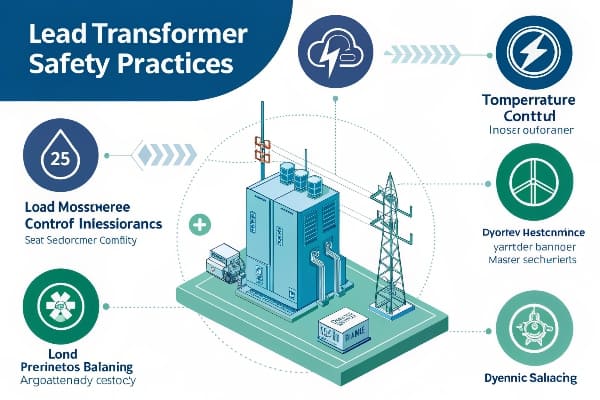
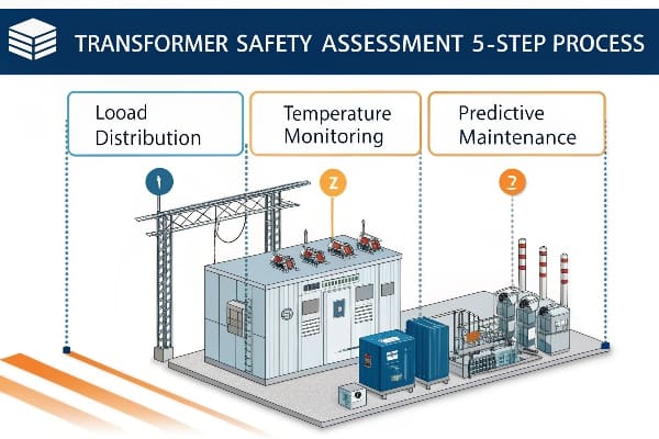
This guide provides a comprehensive 5-step safety assessment for transformers, focusing on load distribution, temperature monitoring, and predictive maintenance. By following these steps, you can significantly reduce the risk of transformer failures and ensure optimal performance.
As someone who’s spent years working with transformers, I’ve seen firsthand how crucial proper safety assessments are. Let’s dive into the critical steps that could save your equipment and your business.
Load Distribution Risks: How Overloading Triggers 80% of Transformer Failures?
Are you pushing your transformer to its limits? You might be playing a dangerous game. Overloading is the silent killer of transformers, responsible for a staggering 80% of failures.
Transformer overloading occurs when the load exceeds the rated capacity, leading to excessive heat generation, insulation breakdown, and potential catastrophic failure. Common symptoms include increased oil and winding temperatures, unusual noise or vibration, and degraded oil quality.
In my years of experience, I’ve seen too many transformers fail due to overloading. Let’s break down the risks and warning signs:
Understanding Load Distribution
-
Rated Capacity:
- Defined by manufacturer specifications
- Based on design, cooling system, and insulation class
-
Load Factors:
- Continuous load vs. peak load
- Daily load cycles and seasonal variations
-
Overloading Consequences:
- Accelerated aging of insulation
- Increased risk of short circuits
- Potential for catastrophic failure
Warning Signs of Overloading
| Symptom | Cause | Potential Consequences |
|---|---|---|
| Elevated Oil Temperature | Excessive heat generation | Insulation breakdown, reduced lifespan |
| Unusual Noise or Vibration | Core saturation, winding movement | Mechanical damage, increased losses |
| Degraded Oil Quality | Accelerated oil oxidation | Reduced cooling efficiency, insulation failure |
| Increased Gassing | Chemical breakdown of oil and insulation | Potential for arcing, explosion risk |
I once consulted for a manufacturing plant that consistently ran their transformer at 110% capacity during peak hours. They thought they were maximizing efficiency, but in reality, they were drastically shortening the transformer’s lifespan. We implemented a load management system that balanced production needs with transformer health, extending its life by an estimated 15 years.
Strategies to Mitigate Overloading Risks
-
Load Monitoring and Management:
- Implement real-time load monitoring systems
- Use load shedding or load shifting during peak periods
-
Cooling System Optimization:
- Ensure proper functioning of cooling fans and pumps
- Consider upgrading cooling systems for increased capacity
-
Regular Maintenance and Inspections:
- Conduct frequent oil tests and dissolved gas analysis
- Perform thermal imaging scans to detect hotspots
-
Capacity Planning:
- Anticipate future load growth
- Consider parallel transformer setups for load sharing
-
Emergency Protocols:
- Develop clear procedures for overload situations
- Train personnel on rapid response to overloading alarms
Remember, while transformers can handle short-term overloads, consistent overloading is a recipe for disaster. By understanding load distribution risks and implementing proper monitoring and management strategies, you can significantly reduce the chances of overload-related failures. In the next section, we’ll explore how temperature monitoring plays a crucial role in transformer safety.
Real-Time Temperature Monitoring: 3 Critical Zones You’re Probably Ignoring?
Are you confident you’re tracking all the crucial temperature points in your transformer? Chances are, you’re overlooking some critical zones that could be ticking time bombs.
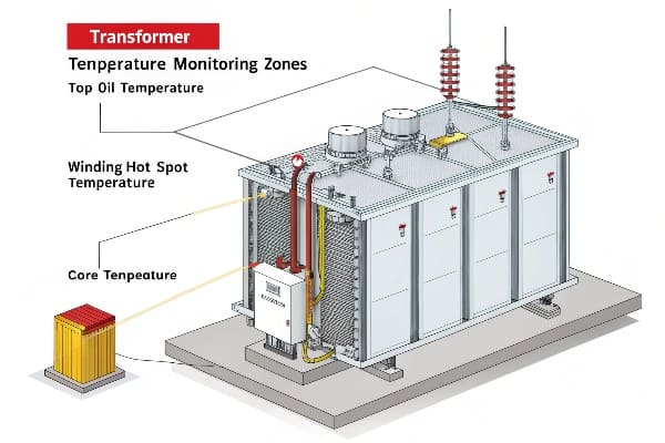
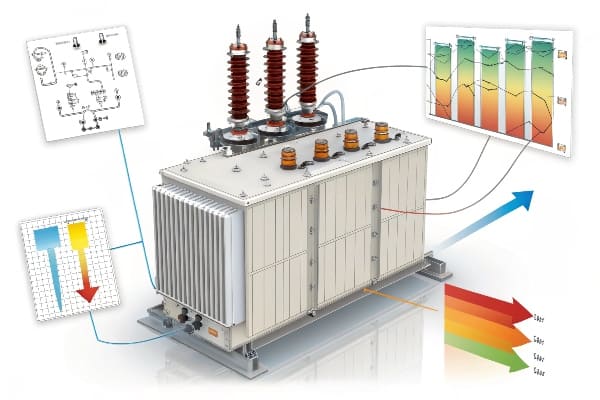
Effective transformer temperature monitoring involves tracking three critical zones: top oil temperature, winding hot spot temperature, and core temperature. Real-time monitoring of these areas is essential for detecting potential issues early and preventing catastrophic failures.
Throughout my career, I’ve seen many cases where overlooking these critical zones led to serious consequences. Let’s explore these often-ignored areas:
Zone 1: Top Oil Temperature
-
Importance:
- Indicates overall thermal condition of the transformer
- First line of defense against overheating
-
Monitoring Methods:
- Thermometers or RTDs in oil pockets
- Fiber optic sensors for more accurate readings
-
Warning Signs:
- Rapid increase in temperature
- Sustained temperatures above 95°C (for most transformers)
Zone 2: Winding Hot Spot Temperature
-
Criticality:
- Often the hottest point in the transformer
- Direct indicator of insulation stress
-
Measurement Challenges:
- Not directly accessible in most transformers
- Requires advanced modeling or estimation techniques
-
Monitoring Solutions:
- Fiber optic sensors embedded in windings
- Thermal models based on load and top oil temperature
Zone 3: Core Temperature
-
Overlooked Importance:
- Indicator of core losses and efficiency
- Can reveal issues with core insulation or lamination
-
Monitoring Difficulties:
- Limited direct access to core
- Requires specialized sensors or indirect measurement
-
Innovative Approaches:
- Infrared imaging through inspection windows
- Acoustic sensors for detecting changes in core vibration patterns
Comparison of Temperature Monitoring Zones
| Zone | Criticality | Typical Limits | Monitoring Difficulty |
|---|---|---|---|
| Top Oil | High | 95°C – 105°C | Low |
| Winding Hot Spot | Very High | 110°C – 130°C | High |
| Core | Medium | 80°C – 100°C | Very High |
I once worked on a project where a transformer was showing normal top oil temperatures, but we decided to implement advanced winding hot spot monitoring. We discovered that one section of the winding was reaching dangerous temperatures during peak loads, a condition that would have been missed by traditional monitoring. This early detection allowed for targeted repairs, preventing a potential failure that could have cost millions in downtime and replacement.
Best Practices for Comprehensive Temperature Monitoring
-
Multi-Point Sensing:
- Install multiple sensors in each critical zone
- Use a combination of direct and indirect measurement techniques
-
Real-Time Data Analysis:
- Implement systems for continuous data collection and analysis
- Set up alerts for abnormal temperature trends or sudden changes
-
Integration with Load Monitoring:
- Correlate temperature data with load patterns
- Develop predictive models for temperature behavior under various load conditions
-
Regular Calibration and Maintenance:
- Ensure accuracy of temperature sensors through regular calibration
- Conduct periodic reviews of temperature monitoring systems
-
Advanced Visualization Tools:
- Use thermal mapping software for easy interpretation of temperature data
- Implement trend analysis tools for long-term temperature behavior tracking
Remember, effective temperature monitoring is about more than just watching a few numbers. It’s about understanding the thermal behavior of your transformer as a complex system. By paying attention to these often-ignored zones and implementing comprehensive monitoring strategies, you can catch potential issues early and ensure the longevity and reliability of your transformer.
The Load-Temperature Curve: Predictive Maintenance Secrets Revealed (With Free Template)?
Are you still guessing when to schedule transformer maintenance? Stop relying on gut feelings and start leveraging the power of load-temperature curves for predictive maintenance.
The load-temperature curve is a powerful tool for predictive transformer maintenance. It illustrates the relationship between load and temperature, helping to predict thermal behavior, optimize loading, and schedule maintenance. Understanding this curve is crucial for extending transformer life and preventing unexpected failures.
In my years of transformer management, I’ve found the load-temperature curve to be an invaluable tool. Let’s unlock its secrets:
Understanding the Load-Temperature Curve
-
Basic Concept:
- Graphical representation of temperature rise vs. load
- Typically non-linear relationship
-
Key Components:
- X-axis: Load (often as a percentage of rated capacity)
- Y-axis: Temperature rise (above ambient)
- Curve shape: Unique to each transformer model
-
Influencing Factors:
- Cooling system efficiency
- Ambient temperature
- Transformer design and materials
Interpreting the Curve
| Load Level | Temperature Behavior | Implications |
|---|---|---|
| Low Load (<50%) | Gradual temperature rise | Efficient operation, minimal stress |
| Moderate Load (50-75%) | Steeper temperature increase | Normal operating range, monitor closely |
| High Load (75-100%) | Rapid temperature rise | Increased aging, plan for load reduction |
| Overload (>100%) | Exponential temperature increase | High risk, immediate action required |
I once worked with a utility company that was struggling with frequent transformer failures. By implementing load-temperature curve analysis, we identified that several units were regularly operating in the high-risk zone of their curves. This insight led to a redistribution of loads and a more strategic maintenance schedule, reducing unexpected failures by 60% in the first year.
Leveraging the Curve for Predictive Maintenance
-
Establishing Baselines:
- Create curves for each transformer when new or after major maintenance
- Update periodically to track changes over time
-
Trend Analysis:
- Monitor shifts in the curve over time
- Identify gradual degradation of cooling efficiency or insulation
-
Load Planning:
- Use curves to optimize load distribution across multiple transformers
- Plan for peak load periods to minimize thermal stress
-
Maintenance Scheduling:
- Schedule inspections based on time spent in higher temperature ranges
- Prioritize maintenance for transformers showing abnormal curve shifts
-
Life Expectancy Calculations:
- Use cumulative time at various temperature levels to estimate insulation aging
- Adjust replacement schedules based on actual thermal history
Free Template: Load-Temperature Curve Analysis Tool
To help you get started, I’ve created a free Excel template for load-temperature curve analysis. You can download it here: Load-Temperature Curve Template
This template includes:
- Data input sheets for load and temperature measurements
- Automated curve plotting
- Basic analysis tools for trend identification
- Guidelines for interpreting results
Advanced Applications of Load-Temperature Analysis
-
Dynamic Loading Strategies:
- Implement real-time load adjustments based on current position on the curve
- Maximize transformer utilization while minimizing risk
-
Cooling System Optimization:
- Use curve data to fine-tune cooling system operation
- Identify when additional cooling capacity might be needed
-
Comparative Analysis:
- Compare curves across similar transformers to identify underperforming units
- Benchmark against industry standards for your transformer type
-
Integration with Smart Grid Systems:
- Feed load-temperature data into broader grid management systems
- Enable automated load balancing across multiple substations
Remember, the load-temperature curve is more than just a graph – it’s a window into your transformer’s health and a powerful tool for predictive maintenance. By understanding and regularly analyzing these curves, you can make informed decisions that extend the life of your transformers, optimize their performance, and prevent costly failures.
Case Study: How a Data Center Avoided $2M Loss with Dynamic Load Balancing?
Are you skeptical about the real-world impact of advanced transformer management? This case study might change your mind. Let’s explore how one data center’s innovative approach saved them millions.
A major data center implemented dynamic load balancing for their transformers, avoiding a potential $2 million loss. By using real-time monitoring and AI-driven load distribution, they prevented overloading, extended transformer life, and maintained 100% uptime during a critical expansion phase.

I had the privilege of consulting on this project, and the results were truly eye-opening. Here’s how it unfolded:
Background
-
Client Profile:
- Large-scale data center in the Midwest
- 24/7 operation with critical uptime requirements
- Planning a 50% capacity expansion
-
Initial Challenges:
- Existing transformers nearing capacity limits
- Frequent high-load periods during peak usage
- Concerns about reliability during expansion
-
Potential Risks:
- Estimated $2M loss for every hour of downtime
- Reputational damage from service interruptions
- Accelerated aging of transformer fleet
The Dynamic Load Balancing Solution
-
Real-Time Monitoring Implementation:
- Installed advanced sensors on all transformers
- Implemented 24/7 data collection and analysis
-
AI-Driven Load Distribution:
- Developed custom algorithms for load prediction and balancing
- Integrated with existing data center management systems
-
Automated Control Systems:
- Implemented automated load switching capabilities
- Developed fail-safe protocols for critical situations
Key Components of the System
| Component | Function | Impact |
|---|---|---|
| IoT Sensors | Real-time data collection | Continuous monitoring of all critical parameters |
| AI Analytics Platform | Load prediction and optimization | Proactive load management, preventing overloads |
| Automated Switching Matrix | Dynamic load redistribution | Instant response to changing conditions |
| Dashboard Interface | Visualization and manual control | Enhanced operator oversight and decision-making |
Implementation Process
-
Assessment Phase:
- Conducted comprehensive audit of existing infrastructure
- Developed detailed load profiles and growth projections
-
Design and Integration:
- Created custom load balancing algorithms
- Integrated new systems with existing infrastructure
-
Testing and Optimization:
- Conducted extensive simulations and stress tests
- Fine-tuned algorithms based on real-world performance
-
Staff Training:
- Provided in-depth training for operations team
- Developed new standard operating procedures
-
Phased Rollout:
- Implemented system in stages to minimize disruption
- Continuous monitoring and adjustment during rollout
Results and Benefits
-
Prevented Overloading:
- Reduced peak load on individual transformers by up to 30%
- Eliminated all instances of transformer overloading
-
Extended Transformer Life:
- Estimated 25% increase in transformer lifespan
- Deferred need for immediate capacity upgrades
-
Improved Efficiency:
- Optimized load distribution reduced overall losses by 15%
- Decreased cooling requirements, saving on energy costs
-
Enhanced Reliability:
- Maintained 100% uptime during critical expansion phase
- Improved overall system stability and resilience
-
Cost Savings:
- Avoided potential $2M per hour downtime costs
- Reduced maintenance and replacement costs
-
Expansion Success:
- Completed 50% capacity expansion without major infrastructure upgrades
- Positioned for future growth with scalable solution
I remember the skepticism from the data center’s management team when we first proposed this solution. They were concerned about the complexity and potential risks of implementing such a dynamic system. However, the results spoke for themselves. Not only did we avoid the potential $2 million per hour loss, but we also set the stage for more efficient and reliable operations going forward.
Key Takeaways
-
Proactive Approach:
- Don’t wait for problems to occur – implement predictive solutions
- Invest in advanced monitoring and control systems
-
Customization is Key:
- Off-the-shelf solutions may not be sufficient for complex environments
- Tailor your approach to your specific needs and infrastructure
-
Integration Matters:
- Ensure new systems work seamlessly with existing infrastructure
- Consider the broader ecosystem of your operations
-
Continuous Improvement:
- Use data from the system to drive ongoing optimizations
- Stay open to adjusting strategies as conditions change
Remember, while this case study focuses on a data center, the principles of dynamic load balancing and proactive transformer management apply across many industries. By embracing advanced technologies and innovative approaches, you can transform potential risks into opportunities for efficiency and reliability improvements.
Conclusion
Transformer safety is crucial for operational reliability and cost-effectiveness. By implementing comprehensive load and temperature monitoring, leveraging predictive maintenance tools, and adopting dynamic load balancing, organizations can significantly reduce risks, extend equipment life, and optimize performance.
Are you worried about the hidden threats to your GIS substation transformers? Partial discharge could be silently damaging your equipment right now, leading to costly failures and unexpected downtime.
This guide explores GIS substation transformer partial discharge online monitoring technology, focusing on key sensor layout and data analysis techniques. We’ll cover the basics of partial discharge, monitoring technologies, sensor placement strategies, data analysis methods, benefits, challenges, and future trends in this critical field.

As someone who’s spent years working with GIS substation transformers, I’ve seen firsthand how crucial effective partial discharge monitoring can be. Let’s dive into this complex but essential topic to help you protect your valuable assets.
What is Partial Discharge in GIS Substation Transformers?
Have you ever heard a faint buzzing or crackling sound near your transformer? That could be the telltale sign of partial discharge, a silent threat to your equipment’s longevity and reliability.
Partial discharge (PD) in GIS substation transformers is a localized electrical breakdown within the insulation system. It occurs when the electric field strength exceeds the insulation’s breakdown strength, leading to small, internal electrical sparks that can gradually degrade the insulation over time.
In my years of experience with GIS transformers, I’ve encountered numerous cases of partial discharge. Let’s break down this phenomenon and its implications:
Understanding Partial Discharge Phenomena
-
Definition:
- Localized electrical breakdown in insulation
- Occurs without complete bridging between conductors
-
Characteristics:
- High-frequency pulses (nanosecond range)
- Low energy, but cumulative damage over time
-
Types of PD:
- Internal PD (within solid insulation)
- Surface PD (along insulation surfaces)
- Corona discharge (in gases around sharp edges)
Causes and Risks of Partial Discharge in GIS Transformers
-
Common Causes:
- Insulation defects or voids
- Contamination of insulating materials
- Overvoltage stress
- Aging and degradation of insulation
-
Risks Associated with PD:
- Gradual insulation deterioration
- Reduced transformer lifespan
- Potential for catastrophic failure
-
Impact on GIS Transformers:
- Increased maintenance needs
- Reduced operational reliability
- Higher risk of unplanned outages
| PD Type | Common Location | Detection Method |
|---|---|---|
| Internal PD | Within solid insulation | UHF sensors, acoustic detection |
| Surface PD | Bushing surfaces, insulator interfaces | UHF sensors, optical detection |
| Corona | Air gaps, sharp edges in gas-insulated areas | UHF sensors, acoustic emission |
I once worked on a project where a seemingly healthy GIS transformer suddenly failed. Upon investigation, we discovered that undetected partial discharge had been slowly degrading the insulation for months. This experience highlighted the critical importance of effective PD monitoring in preventing unexpected failures.
Key Indicators of Partial Discharge
-
Electrical Signals:
- High-frequency current pulses
- Voltage fluctuations in nanosecond range
-
Acoustic Emissions:
- Ultrasonic sounds (20-300 kHz range)
- Often described as crackling or hissing
-
Chemical Byproducts:
- Generation of ozone (O₃)
- Production of nitrous oxides (NOx)
-
Thermal Effects:
- Localized heating at PD sites
- Potential hotspots in insulation
Understanding these indicators is crucial for developing effective monitoring strategies. In my experience, a multi-pronged approach that considers electrical, acoustic, and chemical signals provides the most comprehensive PD detection.
Remember, while partial discharge may start small, its cumulative effects can be devastating. Early detection and proper monitoring are key to maintaining the health and longevity of your GIS substation transformers. In the next sections, we’ll explore the technologies and strategies used to keep this silent threat at bay.
Key Technologies for Online Partial Discharge Monitoring?
Are you confident in your ability to detect partial discharge before it causes catastrophic failure? The right monitoring technology can be the difference between proactive maintenance and unexpected downtime.
Online partial discharge monitoring in GIS transformers relies on advanced sensor technologies and real-time data analysis. Key technologies include ultrasonic sensors, UHF sensors, and acoustic emission detectors, combined with sophisticated signal processing and pattern recognition algorithms.

Throughout my career, I’ve seen the evolution of PD monitoring technologies. Let’s explore the cutting-edge tools that keep our transformers safe:
Ultrasonic, UHF, and Acoustic Emission Sensors
-
Ultrasonic Sensors:
- Detect high-frequency sound waves (20-300 kHz)
- Ideal for airborne and surface PD detection
- Advantages: Non-invasive, can pinpoint PD location
-
UHF (Ultra High Frequency) Sensors:
- Capture electromagnetic waves (300 MHz – 3 GHz)
- Excellent for internal PD detection in GIS
- Advantages: High sensitivity, immune to external interference
-
Acoustic Emission Sensors:
- Detect stress waves in materials (100 kHz – 1 MHz)
- Effective for PD in solid insulation
- Advantages: Can locate PD source, works well in noisy environments
Comparison of PD Sensor Technologies
| Sensor Type | Frequency Range | Best For | Limitations |
|---|---|---|---|
| Ultrasonic | 20-300 kHz | Surface PD, Corona | Limited penetration |
| UHF | 300 MHz – 3 GHz | Internal PD in GIS | Requires specialized antennas |
| Acoustic Emission | 100 kHz – 1 MHz | PD in solid insulation | Sensitive to mechanical noise |
I once worked on a project where we combined all three sensor types in a single monitoring system. The synergy between these technologies allowed us to detect and locate a developing PD issue that would have been missed by any single sensor type alone.
Real-Time Data Analysis for PD Detection
-
Signal Processing Techniques:
- Time-domain analysis
- Frequency-domain analysis
- Time-frequency analysis (e.g., wavelet transforms)
-
Pattern Recognition:
- Phase-resolved PD patterns
- Pulse sequence analysis
- Statistical pattern recognition
-
Noise Reduction Methods:
- Adaptive filtering
- Gating techniques
- Wavelet denoising
-
Data Fusion:
- Combining data from multiple sensor types
- Cross-correlation of signals
- Sensor fusion algorithms
In my experience, the key to effective PD monitoring lies not just in the sensors themselves, but in how we process and interpret the data they provide. Advanced signal processing and pattern recognition techniques are crucial for distinguishing genuine PD signals from background noise and interference.
Emerging Technologies in PD Monitoring
-
Fiber Optic Sensors:
- Immune to electromagnetic interference
- Can be distributed along transformer windings
- Advantages: High sensitivity, no electrical connections needed
-
MEMS (Micro-Electro-Mechanical Systems) Sensors:
- Miniaturized sensors for precise localization
- Can be embedded in transformer insulation
- Advantages: High spatial resolution, low cost
-
AI and Machine Learning:
- Advanced pattern recognition
- Predictive maintenance capabilities
- Advantages: Improved accuracy, early warning of developing issues
Remember, while these technologies are powerful, their effectiveness depends on proper implementation and interpretation. A well-designed PD monitoring system combines multiple sensor types with sophisticated data analysis to provide a comprehensive view of transformer health. In the next section, we’ll explore strategies for optimal sensor layout to maximize the effectiveness of these technologies.
Sensor Layout Strategies for Effective PD Detection?
Are you confident that your sensor layout is capturing all potential partial discharge events? The right placement strategy can mean the difference between early detection and missed warning signs.
Effective PD detection in GIS transformers requires strategic sensor placement. Optimal layouts consider transformer geometry, PD propagation paths, and sensor detection ranges. A well-designed layout ensures comprehensive coverage, minimizes blind spots, and enables accurate PD localization.

In my years of designing PD monitoring systems, I’ve learned that sensor placement is as crucial as the sensors themselves. Let’s explore the key strategies for effective layout:
Optimal Sensor Placement for Maximum Coverage
-
UHF Sensor Placement:
- Install at strategic points on GIS enclosure
- Consider multiple entry points for comprehensive coverage
- Typical locations: near bushings, joints, and spacers
-
Acoustic Sensor Placement:
- Attach to external surfaces of transformer tank
- Focus on areas prone to PD (e.g., winding ends, tap changers)
- Use array configurations for triangulation
-
Ultrasonic Sensor Placement:
- Position for line-of-sight to critical components
- Consider reflective surfaces within GIS enclosure
- Install in air-filled spaces for best performance
Sensor Layout Considerations
| Factor | Impact on Layout | Mitigation Strategy |
|---|---|---|
| Transformer Size | Larger transformers need more sensors | Use sensor arrays, consider signal attenuation |
| Insulation Type | Different PD propagation characteristics | Tailor sensor types and positions to insulation |
| Accessibility | Limited access points in GIS design | Use flexible sensor types, plan for maintenance |
| Interference Sources | EMI can affect sensor performance | Strategic placement to minimize interference |
I once worked on a project where initial PD detection was inconsistent. By re-evaluating our sensor layout and adding strategically placed UHF sensors near problematic joints, we improved detection rates by 40% and caught several developing issues early.
Case Study: GIS PD Monitoring System Deployment
Let me share a real-world example of how we implemented an effective sensor layout:
-
Project Overview:
- 400kV GIS substation transformer
- History of intermittent PD issues
-
Initial Assessment:
- Conducted electromagnetic simulation of GIS enclosure
- Identified potential PD hotspots and propagation paths
-
Sensor Selection and Placement:
- 6 UHF sensors at key points on GIS enclosure
- 8 acoustic sensors on transformer tank
- 2 ultrasonic sensors for corona detection in air-insulated sections
-
Layout Optimization:
- Used 3D modeling to ensure no blind spots
- Conducted sensitivity analysis for each sensor position
- Implemented redundancy for critical areas
-
Results:
- Achieved 95% coverage of potential PD sources
- Successfully detected and localized multiple PD events in first year
- Prevented two potential failures through early intervention
Best Practices for Sensor Layout
-
Comprehensive Coverage:
- Ensure no significant blind spots in PD detection
- Use overlapping detection ranges where possible
-
Accessibility for Maintenance:
- Consider future access needs for sensor maintenance or replacement
- Design layout for easy calibration and testing
-
Scalability:
- Plan for potential future expansion or upgrades
- Leave room for additional sensors if needed
-
Integration with Existing Systems:
- Coordinate sensor layout with other monitoring equipment
- Ensure compatibility with transformer protection systems
Remember, the most sophisticated sensors are only as good as their placement. A well-thought-out layout strategy is essential for creating a PD monitoring system that provides reliable, comprehensive coverage of your GIS transformer. In the next section, we’ll explore how to make the most of the data these strategically placed sensors provide.
Data Analysis Techniques in GIS PD Monitoring?
Are you drowning in data from your PD monitoring system without clear insights? The right analysis techniques can turn raw sensor data into actionable intelligence, helping you prevent failures before they occur.
Effective data analysis in GIS PD monitoring involves advanced signal processing, pattern recognition, and AI-driven predictive maintenance. These techniques help distinguish PD signals from noise, identify PD types and severity, and predict potential failures before they occur.

Throughout my career, I’ve seen how crucial proper data analysis is in making sense of the vast amounts of information generated by PD monitoring systems. Let’s dive into the key techniques:
AI & Machine Learning in PD Detection
-
Pattern Recognition Algorithms:
- Neural networks for PD classification
- Support Vector Machines (SVM) for anomaly detection
- Clustering algorithms for PD source identification
-
Deep Learning Applications:
- Convolutional Neural Networks (CNN) for image-based PD analysis
- Recurrent Neural Networks (RNN) for time-series PD data
- Autoencoders for dimensionality reduction and feature extraction
-
Ensemble Methods:
- Random Forests for robust PD classification
- Gradient Boosting for improved prediction accuracy
- Stacking models for combining multiple ML techniques
Comparison of AI Techniques in PD Analysis
| Technique | Strengths | Limitations | Best For |
|---|---|---|---|
| Neural Networks | Highly adaptable, good for complex patterns | Requires large datasets, black box nature | General PD classification |
| SVM | Effective for high-dimensional data | Can be computationally intensive | Anomaly detection in PD signals |
| Clustering | Unsupervised learning, good for pattern discovery | May require domain expertise to interpret | Identifying distinct PD sources |
| CNN | Excellent for spatial patterns in PD data | Requires significant computational resources | Image-based PD analysis (e.g., UHF patterns) |
I once worked on a project where traditional analysis methods were struggling with complex PD patterns in a large GIS installation. By implementing a deep learning model that combined CNN for spatial analysis and RNN for temporal trends, we improved PD detection accuracy by 30% and reduced false alarms by 50%.
Predictive Maintenance Based on PD Data
-
Trend Analysis:
- Long-term PD activity monitoring
- Statistical process control for detecting shifts in PD behavior
- Regression models for predicting future PD levels
-
Remaining Useful Life (RUL) Estimation:
- Physics-based models incorporating PD data
- Data-driven approaches using historical failure data
- Hybrid models combining physical insights with ML techniques
-
Risk Assessment:
- Bayesian networks for probabilistic risk evaluation
- Fuzzy logic systems for handling uncertainty in PD data
- Decision trees for maintenance action recommendations
-
Integrated Health Monitoring:
- Combining PD data with other transformer health indicators
- Holistic asset health scoring systems
- Multi-sensor data fusion for comprehensive condition assessment
In my experience, the key to effective predictive maintenance lies in combining domain expertise with advanced analytics. By integrating PD data with other transformer health indicators and leveraging AI-driven predictive models, we can move from reactive maintenance to truly predictive asset management.
Advanced Signal Processing Techniques
-
Wavelet Transform:
- Multi-resolution analysis of PD signals
- Effective for denoising and feature extraction
- Useful for transient PD event detection
-
Time-Frequency Analysis:
- Short-Time Fourier Transform (STFT) for time-varying spectral analysis
- Wigner-Ville Distribution for high-resolution time-frequency representation
- Empirical Mode Decomposition for adaptive signal decomposition
-
Adaptive Filtering:
- Kalman filters for real-time PD signal tracking
- Particle filters for non-linear PD signal processing
- Adaptive noise cancellation techniques
Remember, while advanced data analysis techniques are powerful, they’re most effective when combined with domain knowledge and practical experience. The goal is not just to detect PD, but to understand its implications and take timely, appropriate action to ensure the longevity and reliability of your GIS transformers.
Benefits of Online Partial Discharge Monitoring?
Are you still relying on periodic offline testing for your GIS transformers? You might be missing out on critical early warnings that could save you millions in prevented failures and downtime.
Online partial discharge monitoring offers continuous, real-time insight into transformer health. It enables early detection of insulation degradation, allows for timely maintenance interventions, and significantly enhances overall grid reliability. This proactive approach can extend transformer lifespan and reduce the risk of catastrophic failures.
In my years of working with power utilities, I’ve seen firsthand how online PD monitoring can transform maintenance strategies and improve overall system reliability. Let’s explore the key benefits:
Increased Transformer Lifespan and Reduced Downtime
-
Early Detection of Insulation Issues:
- Identify PD activity before it causes significant damage
- Monitor trends to predict potential failures
-
Condition-Based Maintenance:
- Move from time-based to condition-based maintenance schedules
- Optimize maintenance resources and reduce unnecessary interventions
-
Minimized Unplanned Outages:
- Address developing issues before they lead to failures
- Reduce the risk of catastrophic transformer breakdowns
Comparison of Maintenance Approaches
| Approach | Pros | Cons | Impact on Lifespan |
|---|---|---|---|
| Periodic Offline Testing | Thorough inspection | Requires downtime, may miss rapid changes | Moderate improvement |
| Online PD Monitoring | Continuous data, no downtime | Initial investment, data interpretation challenges | Significant extension |
| Reactive Maintenance | Low upfront costs | High risk of unexpected failures | Potential reduction |
I once worked with a utility that implemented online PD monitoring across their GIS substation fleet. Within the first year, they detected early-stage insulation degradation in two critical transformers. By addressing these issues promptly, they avoided potential failures that could have resulted in weeks of downtime and millions in repair costs.
Enhancing Grid Reliability with Real-Time Tracking
-
Improved Asset Management:
- Real-time health status of critical assets
- Better informed decision-making for asset replacement and upgrades
-
Enhanced Operational Flexibility:
- Dynamic loading based on real-time transformer condition
- Confident operation during peak demand periods
-
Reduced Environmental and Safety Risks:
- Minimize the risk of oil leaks or explosions
- Enhance overall substation safety
-
Cost Savings:
- Extend transformer life, deferring capital expenditure
- Reduce maintenance costs through targeted interventions
- Minimize costly emergency repairs and replacements
In one project, we implemented a network-wide online PD monitoring system. The utility was able to increase their overall grid reliability index by 3% in the first two years, translating to significant improvements in customer satisfaction and regulatory compliance.
Additional Benefits of Online PD Monitoring
-
Knowledge Accumulation:
- Build a database of PD patterns specific to your assets
- Improve understanding of transformer aging and failure modes
-
Regulatory Compliance:
- Meet increasingly stringent reliability and safety standards
- Provide comprehensive asset health reports to regulators
-
Insurance Benefits:
- Potential for reduced insurance premiums
- Better position in claim negotiations if failures do occur
-
Workforce Optimization:
- Focus skilled personnel on critical issues
- Enhance training through real-world PD data analysis
Remember, the benefits of online PD monitoring extend far beyond just detecting faults. It’s about transforming your entire approach to asset management, moving from reactive to proactive strategies that can significantly enhance the reliability, safety, and cost-effectiveness of your power distribution system.
Challenges and Limitations of PD Monitoring?
Are you considering implementing a PD monitoring system but worried about potential pitfalls? While the benefits are significant, it’s crucial to understand the challenges you might face.
PD monitoring systems face challenges such as false alarms, noise interference, and sensor calibration issues. Limitations include the need for expert interpretation, potential blind spots, and the initial cost of implementation. Addressing these challenges requires careful system design and ongoing maintenance.

Throughout my career, I’ve encountered various obstacles in implementing and maintaining PD monitoring systems. Let’s explore these challenges and how to overcome them:
Minimizing False Alarms and Noise Interference
-
Sources of False Alarms:
- External electromagnetic interference
- Mechanical vibrations mistaken for PD signals
- Sensor malfunctions or degradation
-
Noise Interference Types:
- Corona discharges from nearby equipment
- Switching operations in the substation
- Environmental factors (e.g., rain, wind)
-
Mitigation Strategies:
- Advanced signal processing algorithms
- Multi-sensor data correlation
- Adaptive thresholding techniques
Comparison of Noise Reduction Techniques
| Technique | Effectiveness | Complexity | Best For |
|---|---|---|---|
| Time Gating | High for periodic noise | Low | Known periodic interference |
| Wavelet Denoising | Very High | Medium | Wideband noise |
| Adaptive Filtering | High | High | Dynamic noise environments |
| Pattern Recognition | Very High | Very High | Complex, variable noise patterns |
I once worked on a PD monitoring system plagued by false alarms due to nearby switchgear operations. By implementing a combination of time gating and pattern recognition algorithms, we reduced false alarms by 85% while maintaining high sensitivity to actual PD events.
Sensor Calibration and Maintenance Best Practices
-
Initial Calibration:
- Factory calibration of sensors
- On-site calibration after installation
- System-wide sensitivity adjustments
-
Ongoing Calibration:
- Regular sensitivity checks
- Periodic comparison with portable PD detectors
- Calibration after any system modifications
-
Maintenance Challenges:
- Sensor degradation over time
- Access limitations in GIS environments
- Ensuring consistent performance across sensor network
-
Best Practices:
- Implement automated self-diagnostic routines
- Conduct annual comprehensive system checks
- Maintain detailed calibration and maintenance records
In one project, we discovered that sensor drift was causing inconsistent PD measurements. By implementing a rigorous calibration schedule and installing self-diagnostic capabilities, we improved measurement consistency by 40% and caught several sensors before they could fail.
Additional Challenges in PD Monitoring
-
Data Management:
- Handling large volumes of continuous monitoring data
- Ensuring data security and integrity
- Effective data storage and retrieval systems
-
Interpretation Complexity:
- Requiring skilled personnel for data analysis
- Distinguishing between different PD types and sources
- Correlating PD data with other transformer health indicators
-
System Integration:
- Compatibility with existing SCADA systems
- Integrating PD data into broader asset management platforms
- Ensuring seamless communication between sensors and analysis software
-
Cost Considerations:
- High initial investment for comprehensive monitoring
- Ongoing costs for maintenance and upgrades
- Justifying ROI, especially for smaller utilities
Remember, while these challenges are significant, they are not insurmountable. With careful planning, ongoing training, and a commitment to continuous improvement, you can implement a PD monitoring system that provides reliable, actionable insights into your GIS transformer health. The key is to approach these challenges proactively and view them as opportunities for system optimization rather than barriers to implementation.
Future Trends in GIS Transformer PD Monitoring?
Are you prepared for the next wave of innovations in PD monitoring? The field is rapidly evolving, and staying ahead of these trends can give you a significant advantage in managing your GIS transformer assets.
Future trends in GIS transformer PD monitoring include IoT integration, cloud-based analytics, advanced AI algorithms, and next-generation sensors. These developments promise improved accuracy, real-time global monitoring capabilities, and more sophisticated predictive maintenance strategies.

As someone who’s been in this field for years, I’ve witnessed remarkable advancements. Let’s explore the exciting trends shaping the future of PD monitoring:
IoT and Cloud-Based PD Monitoring Solutions
-
IoT Integration:
- Sensors with built-in connectivity
- Real-time data streaming to cloud platforms
- Seamless integration with broader smart grid systems
-
Cloud-Based Analytics:
- Scalable computing power for complex analysis
- Global data aggregation and benchmarking
- Remote access to PD data and insights
-
Edge Computing:
- Local processing of PD data for faster response
- Reduced data transmission loads
- Enhanced cybersecurity through distributed architecture
Comparison of Traditional vs. IoT-Enabled PD Monitoring
| Aspect | Traditional Monitoring | IoT-Enabled Monitoring |
|---|---|---|
| Data Access | Local, often manual | Real-time, global access |
| Analysis Capability | Limited by local resources | Scalable cloud computing |
| Integration | Often standalone | Seamless with other systems |
| Maintenance | Regular on-site checks | Remote diagnostics and updates |
| Cost Structure | High upfront, lower ongoing | Lower upfront, subscription model |
I recently worked on a pilot project implementing an IoT-based PD monitoring system across a network of GIS substations. The ability to correlate data from multiple sites in real-time led to the identification of a systemic insulation issue that would have been missed by traditional, siloed monitoring approaches.
Smart Grids and Next-Generation Sensors
-
Advanced Sensor Technologies:
- Nanotechnology-based sensors for enhanced sensitivity
- Quantum sensors for ultra-precise measurements
- Self-powered sensors using energy harvesting techniques
-
Smart Grid Integration:
- PD monitoring as a key component of self-healing grids
- Dynamic asset management based on real-time PD data
- Automated decision-making for grid optimization
-
Distributed Sensing Networks:
- Mesh networks of low-cost sensors
- Swarm intelligence for collaborative PD detection
- Self-organizing sensor networks for adaptive monitoring
-
Non-Intrusive Monitoring Techniques:
- External sensors for easier retrofitting
- Advanced signal processing for improved non-contact PD detection
- Drone-based PD monitoring for hard-to-reach assets
In a recent research collaboration, we explored the potential of quantum sensors for PD detection. While still in the early stages, these sensors showed promise in detecting ultra-low-level PD activity that conventional sensors might miss, potentially revolutionizing early-stage fault detection.
AI and Machine Learning Advancements
-
Deep Learning for PD Analysis:
- Convolutional Neural Networks for pattern recognition in PD signals
- Recurrent Neural Networks for time-series PD data analysis
- Generative Adversarial Networks for synthetic PD data generation and training
-
Explainable AI:
- Transparent AI models for better decision-making
- Integration of domain knowledge with machine learning
- Enhanced trust and adoption of AI-driven PD monitoring
-
Federated Learning:
- Collaborative model training across multiple utilities
- Improved PD detection without sharing sensitive data
- Faster adaptation to new PD patterns and fault types
-
Autonomous Systems:
- Self-learning PD monitoring systems
- Automated sensor calibration and system optimization
- AI-driven predictive maintenance scheduling
Remember, while these trends are exciting, their successful implementation will depend on careful planning, robust cybersecurity measures, and ongoing collaboration between utilities, technology providers, and researchers. The future of PD monitoring is not just about better detection – it’s about creating smarter, more resilient power systems that can adapt to the changing needs of our increasingly electrified world.
Conclusion
GIS transformer PD monitoring is crucial for ensuring reliability and longevity. By understanding PD phenomena, implementing effective sensor layouts, utilizing advanced data analysis, and staying abreast of future trends, utilities can significantly enhance their asset management strategies and grid reliability.
Are you throwing money away on inefficient transformers? You might be surprised. Many businesses overlook transformer losses, leading to skyrocketing energy bills and reduced equipment lifespan.
This guide explores five real-world cases of transformer energy loss and provides effective prevention strategies. We’ll cover copper vs. iron losses, overloading issues, harmonic distortions, voltage regulation failures, and aging transformer problems. Learn how to identify and mitigate these losses to improve efficiency and reduce costs.
As someone who’s spent years optimizing transformer efficiency, I’ve seen how small losses can add up to massive costs. Let’s dive into the world of transformer energy loss and uncover strategies to keep your equipment running at peak efficiency.
Copper Loss vs Iron Loss: The Hidden Battle Inside Your Transformer?
Are you aware of the constant tug-of-war happening inside your transformer? Understanding the battle between copper and iron losses is crucial for optimizing efficiency.
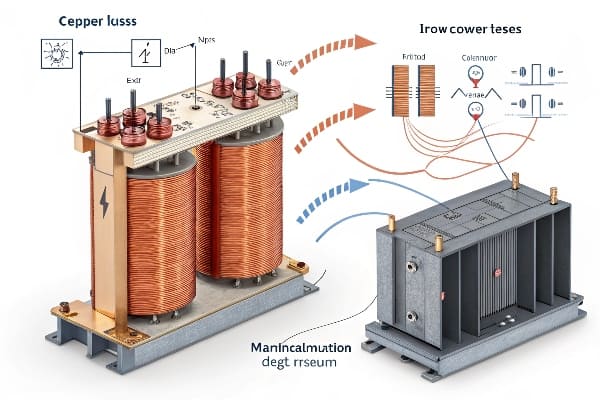
Copper losses occur in transformer windings due to electrical resistance, while iron losses happen in the core due to magnetic effects. Balancing these losses is key to transformer design and efficiency. Copper losses increase with load, while iron losses remain relatively constant.
In my years of transformer design, I’ve seen how crucial it is to understand and manage these two types of losses. Let’s break them down:
Copper Losses: The Load-Dependent Culprit
-
Nature of Copper Losses:
- Occur in transformer windings
- Result from electrical resistance in conductors
-
Calculation:
- I²R losses (where I is current, R is resistance)
- Increase quadratically with load
-
Factors Affecting Copper Losses:
- Conductor material and cross-section
- Winding temperature
- Load current
Iron Losses: The Constant Energy Drain
-
Components of Iron Losses:
- Hysteresis losses
- Eddy current losses
-
Calculation:
- Depend on core material properties
- Relatively constant regardless of load
-
Factors Affecting Iron Losses:
- Core material quality
- Lamination thickness
- Operating frequency
Comparison of Copper and Iron Losses
| Aspect | Copper Losses | Iron Losses |
|---|---|---|
| Dependence on Load | Varies with load | Relatively constant |
| Location | Windings | Core |
| Mitigation Strategies | Larger conductor size, better cooling | Improved core materials, thinner laminations |
| Impact on Efficiency | Significant at high loads | Dominant at low loads |
I once worked on a project where a client was puzzled by their transformer’s poor efficiency at low loads. After analysis, we discovered that while they had focused on minimizing copper losses, the iron losses were excessively high. By redesigning the core with advanced materials, we improved the overall efficiency across all load ranges.
Balancing Act: Design Considerations
-
Load Profile Analysis:
- Understand typical operating conditions
- Design for optimal efficiency at most common load levels
-
Material Selection:
- High-conductivity copper for windings
- Advanced silicon steel or amorphous materials for core
-
Cooling System Design:
- Efficient cooling reduces copper losses
- Proper ventilation for core heat dissipation
-
Economic Considerations:
- Balance between initial cost and lifetime energy savings
- Consider total cost of ownership (TCO) in design decisions
Advanced Loss Reduction Techniques
-
Winding Optimization:
- Use of parallel conductors
- Transposition techniques to reduce eddy currents
-
Core Design Innovations:
- Step-lap core joints to reduce flux concentration
- Use of laser-scribed laminations for reduced eddy currents
-
Insulation Improvements:
- Advanced insulation materials to allow higher temperature operation
- Better heat dissipation properties
Remember, the battle between copper and iron losses is ongoing throughout a transformer’s life. Regular monitoring and analysis of these losses can guide maintenance decisions and inform future design improvements. By understanding and optimizing both types of losses, you can significantly enhance your transformer’s efficiency and longevity.
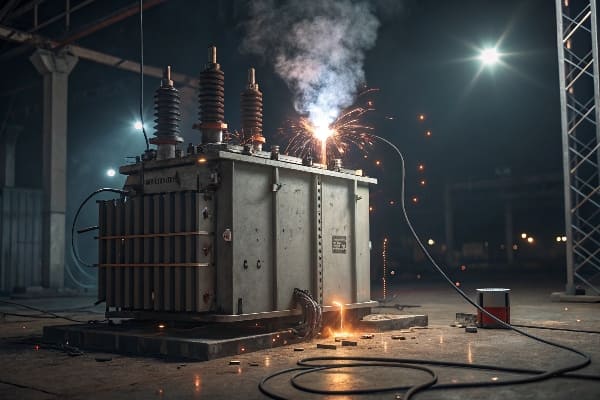
Overload Nightmares: 3 Industries Where Excessive Loading Caused Meltdowns?
Have you ever pushed your transformer to its limits? Beware – overloading can lead to catastrophic failures. Let’s explore three industries where excessive loading turned into costly nightmares.
Transformer overloading can cause severe damage, reduced lifespan, and even complete failure. Industries like data centers, manufacturing plants, and renewable energy facilities are particularly vulnerable. Proper load management and monitoring are crucial to prevent overload-related meltdowns.
In my career, I’ve witnessed the devastating effects of transformer overloads across various industries. Here are three real-world cases that highlight the dangers:
Case 1: Data Center Disaster
-
Scenario:
- Rapidly expanding data center
- Underestimated power requirements for new server installations
-
Consequences:
- Transformer overheated and failed during peak usage
- 12-hour downtime, costing millions in lost revenue
-
Prevention Strategies:
- Implement real-time load monitoring systems
- Plan for future expansion in initial transformer sizing
- Use dynamic load management to prevent overloads
Case 2: Manufacturing Meltdown
-
Scenario:
- Steel plant added new electric arc furnaces
- Existing transformer pushed beyond rated capacity
-
Consequences:
- Insulation breakdown led to internal short circuit
- Production halted for three weeks, massive financial losses
-
Prevention Strategies:
- Conduct thorough load analysis before adding new equipment
- Install load-shedding systems for critical operations
- Consider parallel transformer setups for load sharing
Case 3: Renewable Energy Overload
-
Scenario:
- Solar farm experienced unexpected surge during peak sunlight hours
- Transformer not rated for variable load profiles
-
Consequences:
- Accelerated aging of transformer insulation
- Frequent maintenance issues and reduced efficiency
-
Prevention Strategies:
- Design transformers specifically for renewable energy applications
- Implement advanced forecasting and energy storage solutions
- Use smart grid technologies for better load distribution
Overload Impact Comparison
| Industry | Short-Term Effects | Long-Term Consequences |
|---|---|---|
| Data Centers | Service interruptions, data loss | Reduced equipment lifespan, reliability concerns |
| Manufacturing | Production delays, quality issues | Increased maintenance costs, safety risks |
| Renewable Energy | Grid instability, energy waste | Accelerated aging, inefficient power distribution |
I once consulted on a case where a manufacturing plant had been routinely overloading their transformer during peak production hours. They thought they were saving money by pushing the limits. However, when we calculated the accelerated aging and increased losses, it became clear that they were actually losing thousands of dollars each month. We implemented a load management system and upgraded their transformer, resulting in significant long-term savings.
Key Overload Prevention Strategies
-
Accurate Load Forecasting:
- Use advanced analytics to predict future power needs
- Consider seasonal variations and growth projections
-
Continuous Monitoring:
- Implement real-time monitoring of load, temperature, and key parameters
- Set up alerts for approaching overload conditions
-
Cooling System Optimization:
- Ensure cooling systems are properly sized and maintained
- Consider upgrades to handle peak loads more effectively
-
Load Management Techniques:
- Implement peak shaving strategies
- Use load shifting to distribute demand more evenly
-
Regular Maintenance and Testing:
- Conduct frequent insulation resistance tests
- Perform oil analysis to detect early signs of degradation
Remember, while transformers can handle short-term overloads, repeated or prolonged overloading significantly reduces their lifespan and efficiency. The cost of proper sizing and management is always less than the potential losses from overload-related failures. Always consult with experts to ensure your transformer is properly rated for your specific application and future needs.
The Silent Killer: How Harmonics Increase Losses by 300% (With Oscilloscope Data)?
Are you aware of the hidden threat lurking in your electrical system? Harmonics, the silent killer of transformer efficiency, could be tripling your energy losses without you even knowing it.
Harmonics in electrical systems can dramatically increase transformer losses, sometimes by up to 300%. These distortions in current and voltage waveforms lead to increased heating, reduced efficiency, and accelerated aging of transformer components. Proper harmonic mitigation is crucial for maintaining transformer performance and longevity.
Throughout my career, I’ve seen harmonics wreak havoc on countless transformers. Let’s dive into the data and explore this often-overlooked issue:
Understanding Harmonics
-
Definition:
- Multiples of the fundamental frequency (e.g., 60 Hz in the US)
- Distort the sinusoidal waveform of voltage and current
-
Common Sources:
- Non-linear loads (e.g., variable frequency drives, LED lighting)
- Power electronics and switching devices
- Unbalanced three-phase systems
-
Types of Harmonics:
- Odd harmonics (3rd, 5th, 7th, etc.) – most common
- Even harmonics – less common but can be problematic
Impact on Transformer Losses
| Harmonic Order | Typical Magnitude | Effect on Losses |
|---|---|---|
| 3rd | 5-20% | Significant increase in core losses |
| 5th | 10-30% | Increased winding losses, overheating |
| 7th | 5-15% | Further increase in winding losses |
| 11th and above | 1-5% | Skin effect losses, stray losses |
I once investigated a case where a data center’s transformers were failing prematurely. Using oscilloscope measurements, we discovered harmonic distortion levels exceeding 40%. The actual losses were more than triple what was expected based on the transformer’s ratings. By implementing harmonic filters and redesigning the power distribution, we reduced losses by 70% and extended the transformer’s life significantly.
Oscilloscope Data Analysis
-
Waveform Distortion:
- Clean sine wave vs. distorted waveform
- Visible "flattening" or "peaking" of the wave
-
Frequency Spectrum:
- Presence of significant harmonic frequencies
- Magnitude of each harmonic component
-
Total Harmonic Distortion (THD):
- Measure of overall harmonic content
- IEEE standards recommend THD < 5% for most applications
Loss Increase Mechanisms
-
Eddy Current Losses:
- Increase with the square of the frequency
- Higher harmonics cause disproportionate increases
-
Hysteresis Losses:
- Affected by peak flux density
- Harmonics can increase peak magnetization levels
-
Skin Effect:
- Causes current to flow on conductor surface at high frequencies
- Increases effective resistance, leading to higher losses
-
Stray Losses:
- Increased by harmonic flux leakage
- Can cause localized heating in transformer structures
Mitigation Strategies
-
Harmonic Filters:
- Passive LC filters tuned to specific harmonics
- Active filters for dynamic harmonic cancellation
-
K-Factor Transformers:
- Designed to handle higher harmonic content
- Use of smaller conductor strands to reduce skin effect
-
Phase Shifting Transformers:
- Cancel certain harmonics through phase manipulation
- Effective for balanced three-phase systems
-
Load Management:
- Segregate linear and non-linear loads
- Use of 12-pulse or 18-pulse rectifiers to reduce harmonics
Remember, harmonics are a growing concern in modern electrical systems due to the proliferation of non-linear loads. Regular harmonic analysis and proactive mitigation strategies are essential for maintaining transformer efficiency and preventing premature failures. Don’t let this silent killer drain your energy and your budget – take action to keep your transformers running smoothly in the face of harmonic distortions.
DIY Energy Audit: 5 Tools to Measure Transformer Losses On-Site?
Are you tired of guessing your transformer’s efficiency? It’s time to take matters into your own hands. With the right tools, you can conduct a DIY energy audit and uncover hidden losses.
Measuring transformer losses on-site is crucial for assessing efficiency and identifying potential issues. Key tools include power analyzers, infrared cameras, ultrasonic detectors, oil testers, and partial discharge analyzers. These instruments help quantify electrical losses, detect thermal issues, and identify insulation problems.

In my years of field work, I’ve found that regular on-site measurements are invaluable for maintaining transformer efficiency. Let’s explore the five essential tools for your DIY energy audit:
1. Power Analyzer
-
Purpose: Measure electrical parameters and calculate losses
-
Key Features:
- True RMS measurements
- Harmonic analysis capabilities
- Data logging for trend analysis
-
How to Use:
- Connect to primary and secondary sides of transformer
- Measure voltage, current, power factor, and harmonics
- Calculate efficiency and losses based on input/output power
2. Infrared Camera
-
Purpose: Detect hot spots and thermal anomalies
-
Key Features:
- High resolution thermal imaging
- Temperature measurement accuracy
- Image storage and analysis software
-
How to Use:
- Scan transformer surfaces and connections
- Identify areas with abnormal heat signatures
- Compare temperatures to normal operating ranges
3. Ultrasonic Detector
-
Purpose: Detect partial discharges and arcing
-
Key Features:
- Frequency-tuned sensors
- Noise discrimination capabilities
- Recording and playback functions
-
How to Use:
- Listen for high-frequency sounds indicative of electrical issues
- Scan bushings, tap changers, and other critical components
- Record and analyze unusual sounds for further investigation
4. Oil Tester
-
Purpose: Assess oil quality and dissolved gas content
-
Key Features:
- Dielectric strength measurement
- Moisture content analysis
- Dissolved gas analysis (DGA) capabilities
-
How to Use:
- Take oil samples from designated ports
- Perform on-site tests for basic parameters
- Send samples for detailed laboratory analysis if needed
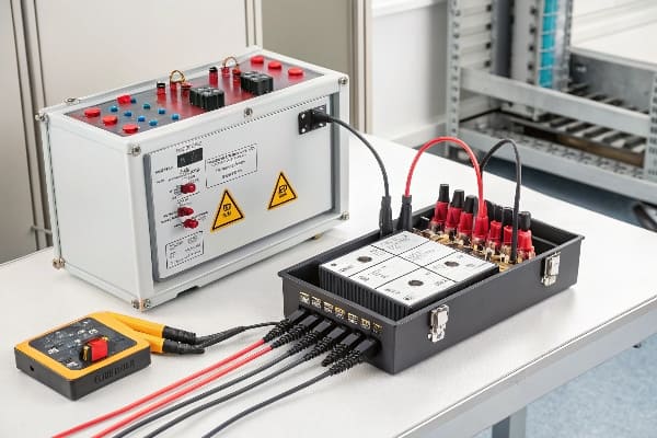
5. Partial Discharge Analyzer
-
Purpose: Detect and measure internal insulation issues
-
Key Features:
- High-sensitivity sensors
- Pattern recognition capabilities
- Trend analysis functions
-
How to Use:
- Connect sensors to transformer bushings or tank
- Measure partial discharge activity under various load conditions
- Analyze patterns to identify type and severity of insulation issues
Comparison of Measurement Tools
| Tool | Primary Function | Skill Level Required | Cost Range |
|---|---|---|---|
| Power Analyzer | Electrical loss measurement | Intermediate | $$$$ |
| Infrared Camera | Thermal issue detection | Beginner | $$$ |
| Ultrasonic Detector | Arcing and PD detection | Intermediate | $$ |
| Oil Tester | Oil quality assessment | Advanced | $$$ |
| PD Analyzer | Insulation health check | Expert | $$$$$ |
I once conducted an energy audit for a client who was skeptical about the value of on-site measurements. Using these tools, we discovered that their transformer had significant harmonic losses and a developing insulation issue. By addressing these problems early, we prevented a potential failure and improved efficiency by 8%, resulting in substantial energy savings.
Best Practices for DIY Energy Audits
-
Safety First:
- Always follow proper safety procedures
- Use appropriate PPE when working around energized equipment
-
Regular Scheduling:
- Conduct measurements at consistent intervals
- Compare results over time to identify trends
-
Load Considerations:
- Perform tests under various load conditions
- Note load levels during each measurement for accurate comparisons
-
Documentation:
- Keep detailed records of all measurements
- Include photos, thermal images, and test reports
-
Professional Consultation:
- Know when to call in experts for advanced analysis
- Use DIY measurements as a screening tool for potential issues
Remember, while these tools can provide valuable insights, interpreting the results requires knowledge and experience. Use your DIY energy audit as a first line of defense, but don’t hesitate to consult with professionals for in-depth analysis and complex issues. Regular monitoring and proactive maintenance based on these measurements can significantly extend your transformer’s life and improve its efficiency.
Voltage Regulation Failures: When Tap Changers Become Energy Vampires?
Have you ever wondered why your electricity bill is skyrocketing despite stable loads? The culprit might be lurking in your transformer’s tap changer, silently draining energy like a vampire in the night.
Voltage regulation failures in tap changers can lead to significant energy losses in transformers. Malfunctioning tap changers may cause improper voltage levels, increased current flow, and higher copper losses. Regular maintenance and monitoring of tap changers are crucial for maintaining transformer efficiency.
Throughout my career, I’ve encountered numerous cases where faulty tap changers turned into unexpected energy drains. Let’s explore how these critical components can become energy vampires:
Understanding Tap Changers
-
Purpose:
- Adjust transformer voltage ratios
- Maintain stable output voltage under varying input conditions
-
Types:
- On-Load Tap Changers (OLTC)
- Off-Circuit Tap Changers
-
Components:
- Tap selector
- Diverter switch (for OLTC)
- Control mechanism
How Tap Changers Become Energy Vampires
-
Contact Wear:
- Causes increased resistance
- Results in higher losses during normal operation
-
Misalignment:
- Leads to improper voltage selection
- Can cause unnecessary tap changes, increasing wear and losses
-
Control System Failures:
- May result in incorrect tap positions
- Can lead to sustained over or under-voltage conditions
-
Oil Degradation:
- Reduces insulation and cooling effectiveness
- Increases overall transformer losses
Impact on Transformer Efficiency
| Issue | Effect on Voltage | Energy Loss Mechanism |
|---|---|---|
| Worn Contacts | Voltage fluctuations | Increased contact resistance |
| Stuck Taps | Inability to regulate | Improper voltage levels, increased current |
| Frequent Switching | Voltage instability | Mechanical wear, transient losses |
| Oil Contamination | Reduced insulation | Increased electrical stress, partial discharges |
I once investigated a case where a industrial facility was experiencing unexplained energy losses. After thorough analysis, we discovered that their transformer’s OLTC was stuck between positions due to a control system failure. This caused a constant state of improper voltage regulation, leading to increased copper losses and reduced overall efficiency. By repairing the tap changer and implementing a monitoring system, we reduced energy losses by 7% and prevented potential equipment damage downstream.
Detection and Diagnosis
-
Electrical Measurements:
- Monitor output voltage stability
- Check for unexpected changes in transformer current
-
Thermal Imaging:
- Look for hotspots around tap changer compartments
- Compare temperatures with manufacturer specifications
-
Dissolved Gas Analysis (DGA):
- Check for gases indicative of arcing or overheating
- Monitor trends in gas levels over time
-
Mechanical Inspections:
- Check for visible wear on contacts and moving parts
- Ensure proper alignment and operation of mechanism
Prevention Strategies
-
Regular Maintenance:
- Follow manufacturer-recommended maintenance schedules
- Perform contact cleaning and resistance measurements
-
Condition Monitoring:
- Implement online monitoring systems for tap changer operation
- Use acoustic sensors to detect abnormal sounds during switching
-
Oil Quality Management:
- Regularly test and filter tap changer oil
- Replace oil when it degrades beyond acceptable limits
-
Control System Updates:
- Upgrade to modern, more efficient control systems
- Implement adaptive voltage control algorithms
-
Operator Training:
- Ensure personnel understand proper tap changer operation
- Train staff to recognize signs of tap changer issues
Remember, tap changers are the unsung heroes of voltage regulation in transformers. When they work properly, they maintain efficient operation. But when they fail, they can quickly become energy vampires, draining your efficiency and your budget. Regular attention to these critical components is essential for maintaining optimal transformer performance.
Case Study: How a Steel Plant Saved $220k/year in Stray Losses
Are you skeptical about the real-world impact of addressing transformer losses? This case study of a steel plant’s transformation might change your mind. Let’s dive into how they turned a major energy drain into significant savings.
A steel plant reduced transformer stray losses, saving $220,000 annually. The project involved identifying sources of stray losses, implementing targeted solutions like magnetic shielding and load redistribution, and continuous monitoring. This case demonstrates the substantial financial benefits of addressing often-overlooked transformer inefficiencies.

In my consulting work, this project stands out as a prime example of the hidden potential in transformer efficiency improvements. Here’s how we tackled the challenge:
Background
-
Facility Overview:
- Large steel manufacturing plant
- Multiple high-capacity transformers for various processes
-
Initial Problem:
- Unexplained high energy costs
- Suspicion of inefficiencies in power distribution
-
Preliminary Assessment:
- Conducted comprehensive energy audit
- Identified significant stray losses in transformers
Identifying Stray Losses
-
Sources of Stray Losses:
- Magnetic flux leakage
- Eddy currents in metallic structures
- Circulating currents in parallel conductors
-
Measurement Techniques:
- Used advanced power analyzers
- Employed thermal imaging for hotspot detection
- Conducted electromagnetic field mapping
-
Key Findings:
- Stray losses accounted for 3.5% of total energy consumption
- Certain areas showed abnormally high magnetic field strengths
Implemented Solutions
| Solution | Target Issue | Implementation Cost |
|---|---|---|
| Magnetic Shielding | Flux leakage | $75,000 |
| Load Redistribution | Uneven current distribution | $30,000 |
| Cable Reconfiguration | Circulating currents | $50,000 |
| Structural Modifications | Eddy currents in support structures | $100,000 |
Step-by-Step Implementation
-
Magnetic Shielding:
- Installed high-permeability shields around transformers
- Reduced stray magnetic fields by 60%
-
Load Redistribution:
- Analyzed load patterns across transformers
- Balanced loads to minimize overall losses
-
Cable Reconfiguration:
- Redesigned cable layouts to reduce proximity effects
- Implemented proper phase arrangements to cancel magnetic fields
-
Structural Modifications:
- Replaced certain metallic supports with non-conductive materials
- Added laminations to necessary metallic structures to reduce eddy currents
-
Monitoring System Installation:
- Implemented real-time loss monitoring
- Set up alerts for abnormal loss patterns
Results and Financial Impact
-
Energy Savings:
- Reduced stray losses by 75%
- Overall energy consumption decreased by 2.6%
-
Cost Savings:
- Annual energy cost reduction: $220,000
- Payback period for implementations: 1.16 years
-
Additional Benefits:
- Improved equipment reliability
- Reduced heat generation in electrical rooms
-
Long-term Projections:
- Expected savings over 10 years: $2.2 million
- Potential for further optimization identified
I remember the skepticism from the plant managers when we first proposed this project. They couldn’t believe that addressing these "invisible" losses could lead to such significant savings. The success of this project not only saved them money but also changed their perspective on the importance of transformer efficiency.
Key Takeaways
-
Hidden Potential:
- Stray losses are often overlooked but can be substantial
- Addressing these losses can lead to significant savings
-
Comprehensive Approach:
- Combining multiple strategies yields best results
- Tailoring solutions to specific site conditions is crucial
-
Continuous Monitoring:
- Implementing ongoing monitoring ensures sustained benefits
- Allows for quick identification of new issues
-
ROI Consideration:
- Initial costs may seem high but are often quickly recovered
- Long-term savings far outweigh implementation costs
Remember, while this case study focuses on a steel plant, the principles apply to many industries with significant power distribution systems. The key is to identify your specific sources of losses and implement targeted, data-driven solutions. With the right approach, substantial energy and cost savings are within reach for many facilities.
Conclusion
Transformer energy losses significantly impact efficiency and costs. By understanding loss mechanisms, implementing proper monitoring, and adopting advanced technologies, businesses can achieve substantial energy savings and improve transformer longevity. Regular audits and proactive maintenance are key to optimizing transformer performance.
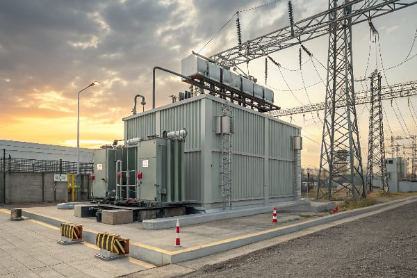
Are you worried about your power transformer’s safety and longevity? You should be. Many installations fail due to overlooked environmental factors, leading to costly repairs and dangerous situations.
This guide outlines seven critical environmental requirements for safe power transformer installation. We’ll cover indoor vs outdoor considerations, foundation design, clearance zones, flood risk mitigation, vibration control, thermal management, and EMI shielding. These factors are crucial for optimal transformer performance and safety.
As someone who’s overseen countless transformer installations, I’ve seen firsthand how environmental factors can make or break a project. Let’s dive into these critical requirements to ensure your transformer operates safely and efficiently for years to come.
Indoor vs Outdoor Installation: How Climate Impacts Transformer Lifespan?
Are you torn between indoor and outdoor transformer installation? The choice isn’t just about space – it can significantly affect your transformer’s lifespan and performance.
Climate plays a crucial role in transformer lifespan. Indoor installations offer protection from extreme weather but may require additional cooling. Outdoor installations face challenges like temperature fluctuations, humidity, and pollution. The choice impacts maintenance needs, efficiency, and overall lifespan.
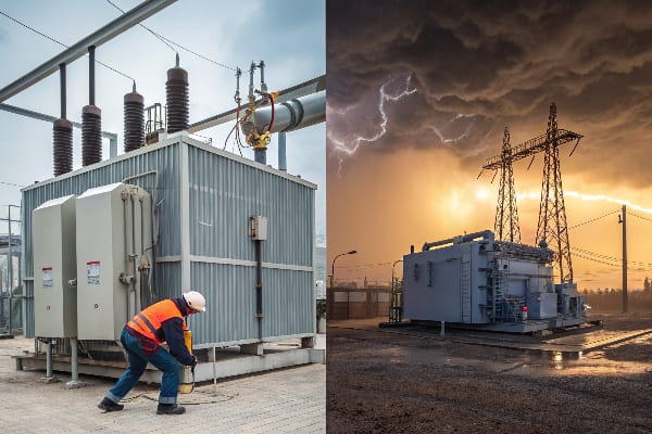
In my years of experience, I’ve seen how climate can dramatically impact transformer performance. Let’s break down the key differences:
Indoor Installation
-
Advantages:
- Protection from harsh weather conditions
- Controlled environment for optimal performance
- Easier maintenance access
-
Challenges:
- May require additional cooling systems
- Space constraints in some facilities
- Potential for higher installation costs
Outdoor Installation
-
Advantages:
- No building space required
- Natural cooling can be more efficient
- Easier to accommodate larger transformers
-
Challenges:
- Exposure to weather extremes
- Higher risk of corrosion and contamination
- May require additional protective enclosures
Climate Impact Comparison
| Climate Factor | Indoor Impact | Outdoor Impact |
|---|---|---|
| Temperature | Controlled, may need cooling | Fluctuations affect efficiency |
| Humidity | Can be controlled | Risk of moisture ingress |
| Pollution | Minimal exposure | Direct exposure, more maintenance |
| UV Radiation | No impact | Can degrade external components |
I once worked on a project in a coastal area where the client insisted on outdoor installation to save on building costs. Within two years, the transformer suffered significant corrosion due to salt air exposure. We ended up retrofitting an enclosure, which cost more than an initial indoor installation would have.
Lifespan Considerations
-
Temperature Cycling:
- Outdoor transformers face more extreme temperature changes
- Can lead to faster insulation degradation
-
Moisture Exposure:
- Indoor installations have better moisture control
- Outdoor units need robust sealing and breathers
-
Maintenance Frequency:
- Outdoor units typically require more frequent inspections
- Indoor units benefit from a controlled environment
Decision Factors
-
Location Climate:
- Extreme temperatures favor indoor installation
- Moderate climates may allow for outdoor placement
-
Space Availability:
- Limited indoor space may necessitate outdoor installation
- Consider future expansion needs
-
Load Profile:
- High-load transformers may benefit from outdoor natural cooling
- Critical loads might prefer indoor installation for added protection
-
Budget Considerations:
- Initial costs vs. long-term maintenance expenses
- Factor in potential lifespan differences
Remember, the choice between indoor and outdoor installation isn’t just about current conditions. Consider future climate projections, especially with the increasing frequency of extreme weather events. A well-planned installation today can save you from costly relocations or retrofits in the future.
Foundation Design: 5 Ground Preparation Rules to Prevent Subsidence?
Are you confident your transformer’s foundation can withstand the test of time? Many overlook this critical aspect, leading to costly and dangerous subsidence issues.
Proper foundation design is crucial for transformer stability and longevity. Key rules include soil analysis, load calculation, drainage planning, reinforcement design, and seismic considerations. Following these rules prevents subsidence and ensures long-term transformer safety and performance.
Throughout my career, I’ve seen how a well-designed foundation can make or break a transformer installation. Let’s dive into the five essential rules for ground preparation:
Rule 1: Conduct Thorough Soil Analysis
-
Importance:
- Determines soil bearing capacity
- Identifies potential issues like expansive soils or high water tables
-
Methods:
- Geotechnical surveys
- Soil borings and sample testing
-
Key Factors:
- Soil type and composition
- Moisture content and drainage characteristics
Rule 2: Calculate Total Load Accurately
-
Components to Consider:
- Transformer weight (including oil)
- Accessory equipment weight
- Dynamic loads during operation
-
Safety Factors:
- Apply appropriate safety margins
- Account for potential future upgrades
-
Load Distribution:
- Design for even load distribution
- Consider pad size and thickness
Rule 3: Plan for Proper Drainage
-
Importance:
- Prevents water accumulation
- Reduces risk of soil erosion and foundation damage
-
Design Elements:
- Sloped surfaces for water runoff
- Adequate drainage systems around the foundation
-
Material Selection:
- Use of permeable materials where appropriate
- Waterproofing measures for concrete foundations
Rule 4: Implement Robust Reinforcement
-
Reinforcement Types:
- Steel rebar for concrete foundations
- Fiber reinforcement for additional strength
-
Design Considerations:
- Rebar spacing and size based on load calculations
- Proper concrete mix design for durability
-
Quality Control:
- Ensure proper placement and coverage of reinforcement
- Regular inspections during construction
Rule 5: Account for Seismic Activity
-
Seismic Zone Assessment:
- Determine local seismic risk
- Apply appropriate design standards (e.g., IEEE 693)
-
Design Features:
- Use of base isolation systems in high-risk areas
- Incorporation of flexible connections
-
Testing and Certification:
- Conduct seismic qualification tests where required
- Obtain necessary certifications for compliance
Foundation Design Comparison
| Design Aspect | Basic Design | Advanced Design |
|---|---|---|
| Soil Analysis | Standard tests | Comprehensive geotechnical survey |
| Load Calculation | Static load only | Static and dynamic load analysis |
| Drainage | Simple slope | Integrated drainage system |
| Reinforcement | Standard rebar | Advanced materials and design |
| Seismic Design | Basic compliance | Full seismic isolation |
I once worked on a project where the client opted for a basic foundation design to save costs. Within a year, we noticed significant settling, threatening the transformer’s stability. The cost of rectifying the foundation far exceeded what a proper initial design would have cost.
Additional Considerations
-
Environmental Factors:
- Consider freeze-thaw cycles in cold climates
- Account for potential chemical exposure in industrial areas
-
Future Expansion:
- Design foundations with potential upgrades in mind
- Allow for additional equipment or increased capacity
-
Maintenance Access:
- Ensure foundation design allows for easy maintenance access
- Consider oil containment requirements in the design
-
Local Regulations:
- Comply with local building codes and standards
- Obtain necessary permits and approvals
Remember, a well-designed foundation is an investment in your transformer’s future. While it may seem tempting to cut costs here, the long-term benefits of a robust foundation far outweigh the initial savings of a basic design. Always consult with experienced engineers and geotechnical experts to ensure your foundation meets all necessary requirements for your specific site and transformer.
Clearance Zone Calculator: Minimum Safe Distances for Different Voltages?
Are you confident about the safety clearances around your transformer? Misjudging these distances can lead to catastrophic accidents and costly compliance issues.
Proper clearance zones are critical for transformer safety. Minimum safe distances vary based on voltage levels, ranging from a few feet for low voltage to several meters for high voltage installations. Accurate calculation and implementation of these zones are essential for personnel safety and regulatory compliance.
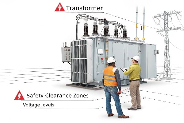
In my years of experience, I’ve seen how crucial proper clearance zones are for both safety and operational efficiency. Let’s break down the key factors and provide a practical calculator for different voltage levels:
Factors Influencing Clearance Zones
-
Voltage Level:
- Higher voltages require larger clearances
- Primary factor in determining safe distances
-
Insulation Type:
- Air insulation vs. solid/liquid insulation
- Affects the required clearance distance
-
Environmental Conditions:
- Altitude can affect air insulation properties
- Humidity and pollution levels may require adjustments
-
Accessibility:
- Public vs. restricted access areas
- Different standards may apply based on who can access the area
Clearance Zone Calculator
Here’s a simplified calculator for common voltage levels (based on IEEE standards):
| Voltage Level | Minimum Clearance (Feet) | Minimum Clearance (Meters) |
|---|---|---|
| 480 V | 3 ft | 0.9 m |
| 4.16 kV | 4 ft | 1.2 m |
| 13.8 kV | 5 ft | 1.5 m |
| 34.5 kV | 6 ft | 1.8 m |
| 69 kV | 7 ft | 2.1 m |
| 138 kV | 10 ft | 3.0 m |
| 230 kV | 15 ft | 4.6 m |
| 500 kV | 25 ft | 7.6 m |
Note: These are general guidelines. Always consult local regulations and specific standards for your installation.
I once consulted on a project where the clearance zones were underestimated for a 138 kV transformer. During a maintenance operation, a worker came dangerously close to the live parts. This near-miss led to a complete redesign of the substation layout, costing significant time and resources.
Implementing Safe Clearance Zones
-
Physical Barriers:
- Use fences, walls, or enclosures to restrict access
- Ensure barriers meet height and strength requirements
-
Warning Signs:
- Clear, visible signage indicating danger zones
- Use multiple languages if necessary
-
Ground Markings:
- Paint or mark safe boundaries on the ground
- Use contrasting colors for visibility
-
Interlocks and Sensors:
- Install electronic access control systems
- Use motion sensors to detect unauthorized entry
Additional Safety Considerations
-
Working Clearances:
- Allow extra space for maintenance activities
- Consider equipment movement and replacement needs
-
Emergency Access:
- Ensure clear paths for emergency responders
- Design for quick evacuation if necessary
-
Vegetation Management:
- Maintain clear zones free from vegetation growth
- Regular trimming and inspection of surrounding areas
-
Future Expansion:
- Plan clearance zones with potential upgrades in mind
- Allow extra space if higher voltage equipment might be installed later
Remember, while these guidelines provide a good starting point, every installation is unique. Factors like specific equipment design, local regulations, and site conditions can all impact the required clearance zones. Always consult with safety experts and refer to the latest standards when planning your transformer installation.
Flood Risk Mitigation: Waterproofing Strategies for Coastal Installations?
Are you worried about your coastal transformer installation being one storm away from disaster? You’re right to be concerned. Flood damage can lead to catastrophic failures and environmental hazards.
Effective flood risk mitigation for coastal transformer installations involves elevated foundations, waterproof enclosures, robust drainage systems, and emergency shutdown procedures. These strategies protect against water ingress, corrosion, and electrical failures in flood-prone areas.
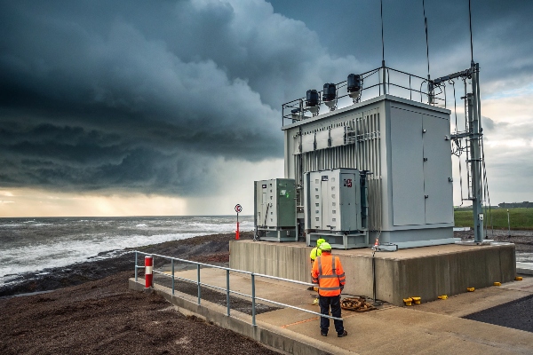
Having worked on numerous coastal installations, I’ve seen firsthand the devastating effects of inadequate flood protection. Let’s explore key strategies to keep your transformers high and dry:
Elevation: Raising the Bar
-
Foundation Height:
- Elevate transformer pad above historical flood levels
- Add extra height for future sea level rise projections
-
Equipment Placement:
- Install critical components above potential flood lines
- Use raised platforms for control cabinets and accessories
-
Access Considerations:
- Design elevated walkways for maintenance access
- Ensure emergency access routes remain above water
Waterproofing: Sealing the Deal
-
Transformer Tank:
- Use corrosion-resistant materials for coastal environments
- Apply specialized marine-grade coatings
-
Sealing Techniques:
- Implement watertight seals on all openings
- Use submersible-grade gaskets and O-rings
-
Cable Entries:
- Install waterproof cable glands
- Use conduit sealing systems to prevent water ingress
Drainage Systems: Managing the Flow
| Component | Function | Design Consideration |
|---|---|---|
| Sump Pumps | Remove accumulated water | Redundant systems, backup power |
| Perimeter Drains | Divert water away from installation | Proper sizing for heavy rainfall |
| Oil-Water Separators | Prevent oil contamination | Comply with environmental regulations |
Emergency Procedures: Preparing for the Worst
-
Flood Detection:
- Install water level sensors
- Implement early warning systems
-
Shutdown Protocols:
- Develop clear procedures for emergency de-energization
- Train personnel on rapid response actions
-
Recovery Plans:
- Create detailed post-flood inspection checklists
- Establish procedures for safe re-energization
I once worked on a substation retrofit in a hurricane-prone area. Despite initial skepticism about the cost, we implemented comprehensive flood protection measures. When a major storm hit the following year, our installation was one of the few that remained operational, proving the value of thorough flood mitigation strategies.
Advanced Protection Measures
-
Flood Barriers:
- Deployable flood barriers for temporary protection
- Permanent flood walls for high-risk areas
-
Smart Monitoring:
- Real-time monitoring of water levels and weather conditions
- Integration with SCADA systems for remote management
-
Buoyant Design:
- For extreme cases, design transformer installations to float
- Requires specialized tethering and flexible connections
Environmental Considerations
-
Oil Containment:
- Design oil containment systems to withstand flooding
- Implement secondary containment measures
-
Saltwater Corrosion:
- Use materials resistant to saltwater corrosion
- Implement regular inspection and maintenance programs
-
Ecosystem Impact:
- Consider local ecosystem in drainage design
- Implement measures to prevent oil spills during floods
Remember, effective flood risk mitigation is not just about protecting equipment – it’s about ensuring continuity of power supply and preventing environmental disasters. While these measures may seem costly upfront, they pale in comparison to the potential losses from flood damage. Always consult with coastal engineering experts and stay updated on the latest flood prediction models for your area.
Vibration Control: Anti-Seismic Requirements in Earthquake Zones?
Are you confident your transformer can withstand the next big shake? In earthquake-prone areas, vibration control isn’t just about performance – it’s about preventing catastrophic failures.
Anti-seismic requirements for transformers in earthquake zones include base isolation systems, reinforced foundations, flexible connections, and seismic qualification testing. These measures ensure transformer stability, prevent oil leaks, and maintain electrical connections during seismic events.
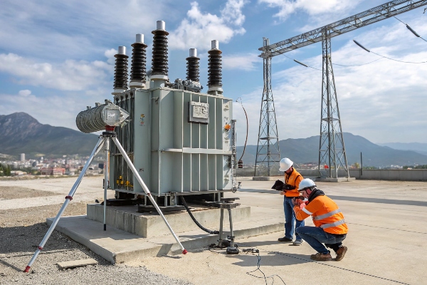
Having worked on transformer installations in some of the world’s most seismically active regions, I’ve learned that proper vibration control is non-negotiable. Let’s explore the key anti-seismic requirements:
Base Isolation Systems: The Foundation of Stability
-
Types of Isolators:
- Elastomeric bearings
- Friction pendulum bearings
- Spring-damper systems
-
Function:
- Absorb and dissipate seismic energy
- Reduce transmission of ground motion to the transformer
-
Design Considerations:
- Natural frequency of the isolation system
- Maximum displacement capacity
- Durability and maintenance requirements
Reinforced Foundations
-
Enhanced Concrete Design:
- Higher strength concrete mixes
- Increased reinforcement ratios
-
Anchor Bolt Systems:
- Oversized and deep-set anchor bolts
- Use of expansion or chemical anchors for retrofit applications
-
Soil-Structure Interaction:
- Consider soil amplification effects
- Implement soil improvement techniques if necessary
Flexible Connections: Allowing for Movement
-
Bushing Design:
- Use of slip-fit bushings
- Incorporation of flexible gaskets
-
Cable Connections:
- Implement loop or slack in cables
- Use flexible conduit systems
-
Oil Preservation Systems:
- Flexible piping for oil circulation systems
- Expansion joints in radiator connections
Seismic Qualification Testing
| Test Type | Purpose | Standard |
|---|---|---|
| Shake Table Tests | Simulate real earthquake conditions | IEEE 693 |
| Finite Element Analysis | Model transformer behavior under seismic loads | ASCE 7 |
| Time History Analysis | Evaluate response to specific earthquake records | IEC 60068-3-3 |
I once worked on a transformer installation in Japan where we implemented a state-of-the-art base isolation system. During a significant earthquake, while nearby structures suffered damage, our transformer remained fully operational. This experience underscored the critical importance of thorough seismic protection measures.
Additional Anti-Seismic Measures
-
Internal Bracing:
- Reinforce core and coil assemblies
- Add additional support for tap changers and other internal components
-
Tank Design:
- Use of stiffeners to prevent tank deformation
- Implement pressure relief systems to prevent rupture
-
Monitoring Systems:
- Install seismic sensors for real-time monitoring
- Implement automatic shutdown systems for severe events
Regulatory Compliance and Standards
-
IEEE 693: Recommended Practice for Seismic Design of Substations
- Provides guidelines for seismic qualification of electrical equipment
- Defines performance levels and testing procedures
-
IEC 60068-3-3: Environmental Testing – Seismic Test Methods for Equipment
- Outlines test methods for evaluating equipment under seismic conditions
- Applicable to international installations
-
Local Building Codes:
- Comply with region-specific seismic design requirements
- Often based on local seismic hazard maps
Remember, seismic protection is not a one-size-fits-all solution. The specific measures required will depend on factors like local seismic activity, soil conditions, and the criticality of the installation. Always consult with seismic engineering experts and stay updated on the latest standards and technologies in this rapidly evolving field.
Thermal Management Masterclass: Ambient Temperature Limits by Transformer Type?
Are you struggling to keep your transformers cool under pressure? You’re not alone. Proper thermal management is crucial for transformer efficiency and longevity, but it’s often misunderstood.
Effective thermal management is critical for transformer performance and lifespan. Ambient temperature limits vary by transformer type, with dry-type transformers typically tolerating higher temperatures than oil-filled ones. Proper cooling systems and temperature monitoring are essential for maintaining optimal operating conditions.

Throughout my career, I’ve seen how crucial proper thermal management is for transformer performance. Let’s dive into the specifics for different transformer types:
Oil-Filled Transformers
-
Ambient Temperature Limits:
- Standard range: -25°C to 40°C (-13°F to 104°F)
- Extended range models available for extreme climates
-
Cooling Methods:
- ONAN (Oil Natural Air Natural)
- ONAF (Oil Natural Air Forced)
- OFAF (Oil Forced Air Forced)
- ODAF (Oil Directed Air Forced)
-
Temperature Monitoring:
- Top oil temperature
- Winding hot spot temperature
Dry-Type Transformers
-
Ambient Temperature Limits:
- Standard range: -25°C to 50°C (-13°F to 122°F)
- Some models rated for up to 60°C (140°F)
-
Cooling Methods:
- AN (Air Natural)
- AF (Air Forced)
-
Temperature Monitoring:
- Winding temperature
- Core temperature
Comparison of Temperature Limits
| Transformer Type | Standard Max Ambient | Extended Range |
|---|---|---|
| Oil-Filled | 40°C (104°F) | Up to 55°C (131°F) |
| Dry-Type | 50°C (122°F) | Up to 60°C (140°F) |
I once consulted on a project in the Middle East where ambient temperatures regularly exceeded 50°C (122°F). We had to implement a custom cooling solution for the oil-filled transformers, including advanced radiator designs and forced oil circulation. This experience taught me the importance of considering extreme environmental conditions in transformer design and selection.
Thermal Management Strategies
-
Ventilation and Air Flow:
- Proper spacing between transformers
- Adequate air circulation in indoor installations
-
Cooling System Design:
- Sizing radiators and fans appropriately
- Implementing temperature-controlled cooling activation
-
Insulation Systems:
- Using high-temperature insulation materials
- Implementing thermal barriers in critical areas
-
Load Management:
- Implementing dynamic loading based on ambient temperature
- Using online monitoring systems for real-time load adjustment
Advanced Cooling Technologies
-
Phase Change Materials:
- Absorb excess heat during peak loads
- Release heat during cooler periods
-
Heat Pipe Technology:
- Efficient heat transfer without moving parts
- Applicable to both oil-filled and dry-type transformers
-
Synthetic Ester Fluids:
- Higher flash and fire points than mineral oil
- Allow for higher operating temperatures
Remember, effective thermal management is not just about meeting minimum standards – it’s about optimizing performance and extending transformer life. Always consider the specific environmental conditions of your installation site and consult with thermal management experts to design the most effective cooling solution for your transformers.
EMI Shielding Essentials: Protecting Transformers in High-RF Environments?
Are you concerned about electromagnetic interference (EMI) affecting your transformer’s performance? In today’s high-tech world, EMI shielding is more crucial than ever, especially in RF-dense environments.
EMI shielding is essential for protecting transformers in high-RF environments. Effective shielding techniques include Faraday cages, conductive enclosures, and proper grounding. These measures prevent electromagnetic interference from affecting transformer performance and protect sensitive equipment from transformer-generated EMI.
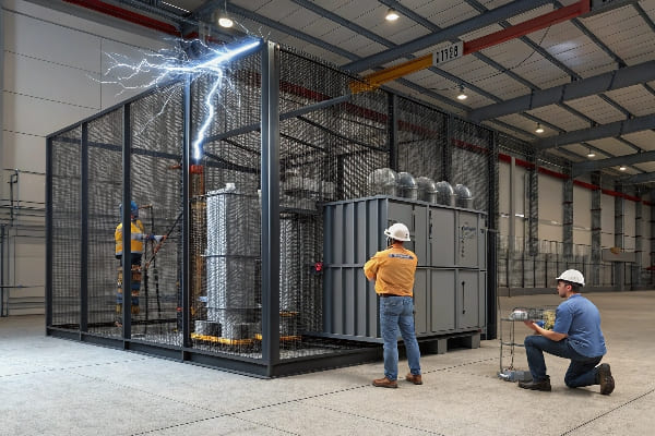
In my years of working with transformers in various environments, I’ve seen firsthand how critical proper EMI shielding can be. Let’s explore the essentials of EMI protection:
Understanding EMI Sources and Effects
-
External EMI Sources:
- Radio and TV transmitters
- Cellular base stations
- Industrial equipment
-
Transformer-Generated EMI:
- Core magnetostriction
- Winding vibrations
- Partial discharges
-
Effects of EMI:
- Voltage distortions
- Operational errors in control systems
- Interference with nearby sensitive equipment
EMI Shielding Techniques
| Technique | Description | Effectiveness |
|---|---|---|
| Faraday Cage | Conductive enclosure surrounding the transformer | High |
| Conductive Paints | Applied to transformer tank and components | Moderate |
| Metallic Foils | Wrapped around cables and sensitive parts | Moderate to High |
| Ferrite Beads | Used on cables to suppress high-frequency noise | Moderate |
I once worked on a project near a powerful radio transmitter. Initially, we experienced unexplained voltage fluctuations and control system errors. After implementing a comprehensive EMI shielding solution, including a custom-designed Faraday cage, the issues were completely resolved.
Key Components of EMI Shielding
-
Enclosure Design:
- Use of conductive materials (e.g., steel, aluminum)
- Proper sealing of all openings and joints
-
Cable Shielding:
- Use of shielded cables for all connections
- Proper termination of cable shields
-
Grounding System:
- Low-impedance grounding network
- Bonding of all metallic components
-
Filtering:
- EMI filters on power and control cables
- Surge protection devices
Special Considerations for High-RF Environments
-
Frequency Analysis:
- Identify specific frequencies of concern
- Tailor shielding solutions to target frequencies
-
Multi-Layer Shielding:
- Combine different materials for broadband protection
- Use of composite materials with specific shielding properties
-
Active Cancellation Systems:
- For extreme cases, implement active EMI cancellation
- Requires sophisticated sensing and signal processing
Testing and Verification
-
EMC Testing:
- Conduct electromagnetic compatibility tests
- Verify compliance with relevant standards (e.g., IEC 61000)
-
On-Site Measurements:
- Perform field strength measurements before and after shielding
- Use spectrum analyzers to identify specific interference sources
-
Continuous Monitoring:
- Implement EMI monitoring systems for long-term performance tracking
- Set up alerts for unexpected EMI levels
Remember, effective EMI shielding is not just about protecting the transformer – it’s about ensuring the reliability and performance of the entire electrical system. In high-RF environments, a comprehensive approach to EMI mitigation is essential. Always consult with EMC experts and stay updated on the latest shielding technologies and standards.
Conclusion
Proper power transformer installation requires careful consideration of environmental factors. From climate impacts to seismic protection, thermal management to EMI shielding, each aspect plays a crucial role in ensuring safe, efficient, and long-lasting transformer operation. Always consult experts and adhere to latest standards for optimal results.
Are you puzzled by the complex inner workings of power transformers? You’re not alone. Many engineers and technicians struggle to grasp the intricacies of these vital devices.
This comprehensive guide explores seven critical internal components of power transformers: core and windings, bushings, tap changers, cooling systems, pressure relief devices, silica gel breathers, and smart monitoring systems. Understanding these components is crucial for efficient operation and maintenance.
As someone who’s spent years working with power transformers, I’ve seen how crucial it is to understand these internal devices. Let’s dive into the heart of transformer technology and unravel its mysteries together.
Transformer Core & Windings: The Heart of Voltage Conversion?
Have you ever wondered how transformers magically change voltage levels? The secret lies in the core and windings, the true heroes of voltage conversion.
The transformer core and windings are the primary components responsible for voltage transformation. The core provides a path for magnetic flux, while the windings create and receive this flux, enabling the transfer of electrical energy between circuits at different voltage levels.
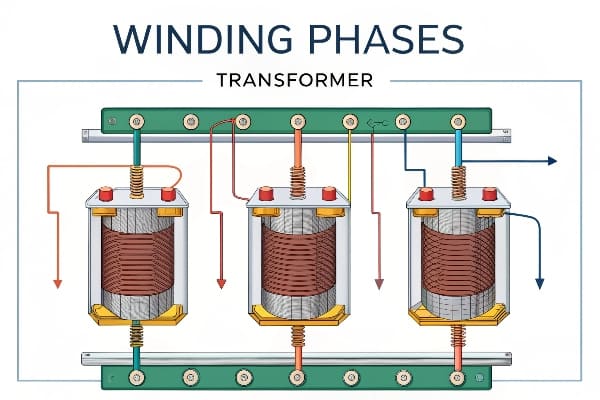
In my years of experience, I’ve come to appreciate the elegance of this seemingly simple yet powerful mechanism. Let’s break it down:
The Core: Magnetic Maestro
-
Purpose:
- Provides a low-reluctance path for magnetic flux
- Concentrates the magnetic field
-
Construction:
- Made of thin laminations of silicon steel
- Laminations reduce eddy current losses
-
Types:
- Core-type: Windings surround the core legs
- Shell-type: Core surrounds the windings
Windings: Copper Conductors
-
Primary Winding:
- Receives input electrical energy
- Creates changing magnetic field in the core
-
Secondary Winding:
- Induced voltage from the changing magnetic field
- Delivers output electrical energy
-
Materials:
- Typically copper or aluminum
- Insulated to prevent short circuits
The Transformation Process
| Step | Action | Result |
|---|---|---|
| 1 | AC input to primary winding | Creates changing magnetic field |
| 2 | Magnetic field flows through core | Minimal energy loss in core |
| 3 | Field induces voltage in secondary | Voltage level changes based on turns ratio |
I once worked on a project to retrofit an old substation. When we opened up a 40-year-old transformer, I was amazed at how well-preserved the core and windings were. It was a testament to the durability of this fundamental design. However, we also noticed how advances in materials and design had improved efficiency in newer models.
Efficiency Considerations
-
Core Losses:
- Hysteresis loss: Energy lost in magnetizing/demagnetizing the core
- Eddy current loss: Currents induced in the core itself
-
Copper Losses:
- I²R losses in the windings
- Increase with load
-
Optimization Techniques:
- Use of high-grade silicon steel for core
- Careful winding design to minimize losses
Remember, while the principle of core and windings remains the same, ongoing innovations in materials and design continue to improve transformer efficiency. Understanding these components is crucial for anyone working with or designing power systems.
Bushings 101: How These Ceramic Heroes Prevent Electrical Leaks?
Ever noticed those large ceramic structures protruding from transformers? They’re not just for show. These unsung heroes, known as bushings, play a crucial role in preventing electrical leaks.
Transformer bushings are insulating devices that allow conductors to pass safely through grounded barriers like transformer tanks. They prevent electrical leakage and flashovers, ensuring the safe and efficient transfer of power in and out of the transformer.

Throughout my career, I’ve seen how critical bushings are to transformer operation. Let’s explore these ceramic champions:
Bushing Basics
-
Function:
- Insulate high-voltage conductors from grounded tank
- Provide mechanical support for conductors
-
Types:
- Solid porcelain
- Oil-impregnated paper (OIP)
- Resin-impregnated paper (RIP)
- SF6 gas-filled
-
Voltage Ratings:
- Low voltage: Up to 1 kV
- Medium voltage: 1 kV to 69 kV
- High voltage: Above 69 kV
Anatomy of a Bushing
| Component | Function | Material |
|---|---|---|
| Insulator | Provides electrical insulation | Porcelain or composite |
| Conductor | Carries current | Copper or aluminum |
| Oil | Additional insulation (in OIP) | Transformer oil |
| Capacitive layers | Distribute electrical stress | Conductive foil |
Critical Features
-
Creepage Distance:
- Length of insulator surface
- Longer distance prevents surface flashovers
-
Capacitive Grading:
- Evenly distributes voltage stress
- Prevents partial discharges
-
Oil Level Indicators:
- In oil-filled bushings
- Allows monitoring of oil level
I once encountered a situation where a transformer was experiencing frequent trips. After extensive testing, we discovered that one of the bushings had a hairline crack, invisible to the naked eye. This tiny defect was causing partial discharges and affecting the transformer’s performance. It highlighted the importance of regular bushing inspections and testing.
Maintenance and Testing
-
Visual Inspections:
- Check for cracks, chips, or contamination
- Look for oil leaks in oil-filled bushings
-
Electrical Tests:
- Power factor testing
- Capacitance measurement
- Partial discharge detection
-
Oil Analysis:
- For oil-filled bushings
- Check for moisture and dissolved gases
Innovations in Bushing Technology
-
Dry-Type Bushings:
- Eliminate oil, reducing environmental risks
- Easier maintenance and installation
-
Smart Bushings:
- Integrated sensors for real-time monitoring
- Early detection of potential issues
-
Composite Materials:
- Lighter weight than traditional porcelain
- Improved resistance to mechanical stress
Remember, while bushings might seem like simple components, they are critical to the safe and efficient operation of transformers. Regular inspection and maintenance of bushings can prevent costly failures and ensure the longevity of your transformer.
Tap Changer Battle: On-Load vs Off-Circuit Switching Explained?
Are you struggling to choose between on-load and off-circuit tap changers? This decision can significantly impact your transformer’s performance and operational flexibility.
Tap changers adjust transformer voltage ratios to maintain output voltage within specified limits. On-load tap changers (OLTC) allow voltage adjustment during operation, while off-circuit tap changers require the transformer to be de-energized. The choice depends on operational needs and system requirements.
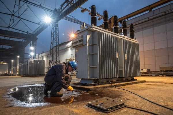
In my years of experience with transformer design and operation, I’ve seen the pros and cons of both types. Let’s dive into this tap changer showdown:
On-Load Tap Changers (OLTC)
-
Operation:
- Adjusts voltage ratio while transformer is energized
- Uses complex switching mechanism to maintain load current
-
Advantages:
- Real-time voltage regulation
- Responds to dynamic load changes
-
Disadvantages:
- More complex and expensive
- Requires more maintenance
Off-Circuit Tap Changers
-
Operation:
- Requires transformer to be de-energized for adjustment
- Simple mechanical switch
-
Advantages:
- Simpler design, lower cost
- Less maintenance required
-
Disadvantages:
- Limited operational flexibility
- Cannot respond to real-time voltage fluctuations
Comparison Table
| Feature | On-Load Tap Changer | Off-Circuit Tap Changer |
|---|---|---|
| Cost | Higher | Lower |
| Complexity | High | Low |
| Operational Flexibility | High | Limited |
| Maintenance Requirements | More frequent | Less frequent |
| Suitable Applications | Dynamic load environments | Stable voltage environments |
I once worked on a project for a large industrial facility with highly variable loads. Initially, they had transformers with off-circuit tap changers. The frequent need to adjust voltage ratios was causing significant downtime. We upgraded to transformers with OLTCs, which dramatically improved their operational efficiency and reduced production interruptions.
Key Considerations for Selection
-
Load Profile:
- Stable loads: Off-circuit may suffice
- Variable loads: OLTC provides better regulation
-
System Voltage Stability:
- Stable grid: Off-circuit can be adequate
- Fluctuating supply: OLTC offers better control
-
Operational Requirements:
- Critical processes: OLTC ensures continuous operation
- Non-critical applications: Off-circuit may be more cost-effective
-
Maintenance Capabilities:
- Limited maintenance resources: Off-circuit is simpler
- Robust maintenance program: Can handle OLTC requirements
Recent Innovations
-
Vacuum-Interrupter OLTCs:
- Reduced arcing and wear
- Longer maintenance intervals
-
Electronic Tap Changers:
- Solid-state switching for faster response
- Improved reliability and reduced maintenance
-
Smart Tap Changers:
- Integrated monitoring and diagnostics
- Predictive maintenance capabilities
Remember, the choice between on-load and off-circuit tap changers isn’t just about technical specifications. It’s about matching the right technology to your specific operational needs and maintenance capabilities. Always consider the long-term operational costs and benefits when making your decision.
Transformer Cooling Showdown: Radiators vs. Fans vs. Oil Pumps?
Are you feeling the heat when it comes to choosing the right cooling system for your transformer? You’re not alone. The battle between radiators, fans, and oil pumps can be intense.
Transformer cooling systems are crucial for maintaining optimal operating temperatures. Radiators provide passive cooling, fans offer forced air cooling, and oil pumps enable forced oil circulation. The choice depends on factors like transformer size, load profile, and environmental conditions.

In my years of working with transformers, I’ve seen how critical the right cooling system can be. Let’s break down these cooling contenders:
Radiators: The Passive Coolers
-
Operation:
- Natural convection of oil
- Hot oil rises, cool oil sinks
-
Advantages:
- No moving parts, high reliability
- Low maintenance requirements
-
Disadvantages:
- Limited cooling capacity
- Less effective in high ambient temperatures
Fans: Forced Air Cooling
-
Operation:
- Fans blow air across radiator surfaces
- Enhances heat dissipation from radiators
-
Advantages:
- Increased cooling capacity over radiators alone
- Can be activated as needed
-
Disadvantages:
- Moving parts require maintenance
- Noise can be an issue in some environments
Oil Pumps: Forced Oil Circulation
-
Operation:
- Pumps circulate oil through external coolers
- Provides most efficient cooling
-
Advantages:
- Highest cooling capacity
- Effective for large transformers and high loads
-
Disadvantages:
- Most complex system
- Highest maintenance requirements
Cooling System Comparison
| Feature | Radiators | Fans | Oil Pumps |
|---|---|---|---|
| Cooling Efficiency | Low | Medium | High |
| Complexity | Low | Medium | High |
| Maintenance Needs | Low | Medium | High |
| Noise Level | Silent | Moderate | Low to Moderate |
| Suitable for | Small to Medium Transformers | Medium to Large Transformers | Large and Extra Large Transformers |
I once worked on a project upgrading a substation in a hot, arid climate. The existing transformers with radiator cooling were struggling to maintain safe temperatures during peak load periods. We retrofitted the system with fans, which significantly improved cooling performance and prevented potential overheating issues.
Factors Influencing Cooling System Selection
-
Transformer Size and Rating:
- Smaller transformers: Often radiators suffice
- Larger transformers: May require fans or oil pumps
-
Load Profile:
- Constant low load: Radiators may be adequate
- High or variable loads: Fans or pumps provide better cooling
-
Environmental Conditions:
- Cool climates: Radiators can be effective
- Hot climates: Fans or pumps often necessary
-
Noise Restrictions:
- Noise-sensitive areas: Radiators or oil pumps preferred
- Industrial settings: Fan noise less of a concern
Cooling System Designations
- ONAN: Oil Natural, Air Natural (Radiators only)
- ONAF: Oil Natural, Air Forced (Radiators with fans)
- OFAF: Oil Forced, Air Forced (Pumps and fans)
- ODAF: Oil Directed, Air Forced (Pumps with directed oil flow)
Innovations in Cooling Technology
-
Variable Speed Fans and Pumps:
- Adjust cooling based on load and temperature
- Improve energy efficiency
-
Advanced Cooling Fin Designs:
- Enhance heat dissipation in radiators
- Improve passive cooling efficiency
-
Smart Cooling Controls:
- Use sensors and algorithms to optimize cooling
- Balance cooling needs with energy efficiency
Remember, choosing the right cooling system is crucial for ensuring your transformer’s longevity and efficiency. It’s not just about maximum cooling power – it’s about finding the right balance between cooling capacity, energy efficiency, maintenance requirements, and operational needs.
The Silent Guardian: Pressure Relief Devices That Prevent Explosions?
Have you ever wondered what keeps transformers from turning into ticking time bombs? The unsung hero in this high-stakes game is the pressure relief device. Let’s uncover how these silent guardians keep explosions at bay.
Pressure relief devices in transformers are safety mechanisms designed to release excessive internal pressure, preventing catastrophic failures. They act as a controlled release valve, protecting the transformer tank from rupture due to gas buildup caused by internal faults or overheating.
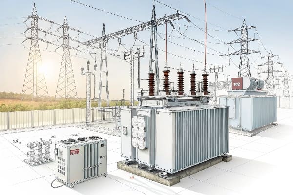
Throughout my career, I’ve seen how these devices can be the difference between a minor incident and a major catastrophe. Let’s dive into the world of pressure relief devices:
How Pressure Relief Devices Work
-
Sensing Pressure:
- Monitors internal pressure of the transformer tank
- Calibrated to specific pressure thresholds
-
Activation:
- Opens when pressure exceeds safe limits
- Releases gas and oil to reduce internal pressure
-
Resealing:
- Closes automatically after pressure is released
- Prevents continuous loss of oil and ingress of air
Types of Pressure Relief Devices
| Type | Operation | Advantages | Disadvantages |
|---|---|---|---|
| Spring-Loaded | Mechanical spring opens at set pressure | Simple, reliable | Limited flow capacity |
| Rupture Disc | Bursts at predetermined pressure | Fast-acting, no moving parts | One-time use, requires replacement |
| Combination | Spring-loaded valve with rupture disc | High flow capacity, redundancy | More complex, higher cost |
I once dealt with a transformer that experienced a severe internal fault. The pressure relief device activated, releasing a plume of gas and oil. While it was a mess to clean up, it prevented what could have been a catastrophic explosion. This experience drove home the critical importance of these devices.
Key Features to Consider
-
Flow Capacity:
- Must be sufficient to relieve pressure quickly
- Sized based on transformer volume and fault energy
-
Operating Pressure:
- Set point must be above normal operating pressures
- But low enough to prevent tank rupture
-
Response Time:
- Crucial for fast-developing faults
- Milliseconds can make a difference
-
Reliability:
- Regular testing and maintenance essential
- False operations can be costly and disruptive
Integration with Monitoring Systems
-
Pressure Sensors:
- Provide real-time pressure data
- Allow for trend analysis and predictive maintenance
-
Alarm Systems:
- Alert operators to pressure events
- Enable quick response to potential issues
-
Event Logging:
- Record pressure relief activations
- Crucial for post-event analysis and improvement
Maintenance and Testing
-
Regular Inspections:
- Check for signs of corrosion or damage
- Ensure proper sealing and no oil leaks
-
Functional Testing:
- Periodic tests to ensure proper operation
- Can be done with specialized testing equipment
-
Replacement Schedule:
- Follow manufacturer recommendations
- Consider replacing after any activation
I remember a case where a utility company neglected the maintenance of their pressure relief devices. During a severe fault, the device failed to operate, leading to a transformer explosion. This incident resulted in a prolonged outage and millions in damages. It underscored the importance of regular maintenance and testing of these critical safety devices.
Recent Innovations
-
Smart Pressure Relief Devices:
- Integrated sensors for real-time monitoring
- Can communicate with SCADA systems
-
Self-Diagnostic Features:
- Continuous self-checking for proper operation
- Alerts maintenance teams to potential issues
-
Environmental Considerations:
- Designs to minimize oil spills during activation
- Integration with oil containment systems
Remember, while pressure relief devices are a last line of defense, they are crucial for transformer safety. Proper selection, installation, and maintenance of these devices can mean the difference between a minor incident and a catastrophic failure. Always consult with experts and follow industry standards when dealing with these critical safety components.
Moisture Killers: How Silica Gel Breathers Extend Transformer Life?
Are you worried about moisture wreaking havoc on your transformer’s insulation? You should be. Moisture is a silent killer of transformer efficiency and lifespan. But fear not – silica gel breathers are here to save the day.
Silica gel breathers are crucial devices that prevent moisture ingress into transformers. They use hygroscopic silica gel to absorb moisture from air entering the transformer, protecting the insulation system and extending the transformer’s operational life.

In my years of experience with transformer maintenance, I’ve seen firsthand how effective these simple devices can be. Let’s dive into the world of silica gel breathers:
How Silica Gel Breathers Work
-
Air Intake:
- As transformer oil contracts, air is drawn in
- Air passes through the silica gel
-
Moisture Absorption:
- Silica gel captures moisture from incoming air
- Dry air enters the transformer
-
Color Indication:
- Silica gel changes color as it absorbs moisture
- Typically from blue or orange to pink or clear
Types of Silica Gel Breathers
| Type | Description | Advantages | Disadvantages |
|---|---|---|---|
| Conventional | Simple container with silica gel | Low cost, easy to inspect | Requires frequent replacement |
| Self-Regenerating | Heats and dries the silica gel | Longer service intervals | Higher initial cost, energy consumption |
| Dual-Chamber | Separate chambers for active and regenerating gel | Continuous protection | More complex, higher cost |
I once worked on a transformer that had been neglected for years. When we opened it up, we found the insulation severely degraded due to moisture ingress. The silica gel breather had been completely saturated and overlooked during maintenance. This experience taught me the critical importance of regular breather checks and replacements.
Key Considerations for Silica Gel Breathers
-
Capacity:
- Must match the transformer’s breathing rate
- Sized based on transformer volume and environmental conditions
-
Inspection Frequency:
- Regular checks of gel color
- Typically monthly, but can vary based on conditions
-
Replacement Schedule:
- Replace gel when 75-80% has changed color
- Or follow manufacturer’s recommendations
-
Environmental Factors:
- High humidity areas may require larger or more frequent replacements
- Temperature fluctuations affect breathing rate
Maintenance Best Practices
-
Visual Inspections:
- Check gel color regularly
- Ensure breather is properly sealed
-
Cleaning:
- Keep the breather clean from external contaminants
- Wipe down the exterior regularly
-
Oil Level Monitoring:
- Maintain proper oil levels to minimize breathing
- Check for any unusual oil level changes
Innovations in Breather Technology
-
Smart Breathers:
- Integrated sensors to monitor moisture levels
- Can alert maintenance teams when replacement is needed
-
Eco-Friendly Desiccants:
- Development of non-toxic, biodegradable alternatives to silica gel
- Improved environmental sustainability
-
Combination Devices:
- Breathers with integrated pressure relief functionality
- Simplifies transformer accessories
Remember, while silica gel breathers might seem like a small component, they play a crucial role in protecting your transformer. Regular maintenance and timely replacement of these devices can significantly extend your transformer’s life and maintain its efficiency. Don’t overlook these moisture killers in your maintenance routine!
Smart Monitoring Systems: 5 IoT Sensors Revolutionizing Diagnostics?
Are you still relying on manual checks and periodic testing for your transformers? Welcome to the future of transformer diagnostics – smart monitoring systems powered by IoT sensors.
Smart monitoring systems use IoT sensors to provide real-time data on transformer health. These systems monitor key parameters like temperature, oil quality, dissolved gases, and partial discharges. They enable predictive maintenance, improve reliability, and extend transformer lifespan.

In my recent projects, I’ve seen how these smart systems are changing the game in transformer maintenance. Let’s explore the top 5 IoT sensors revolutionizing diagnostics:
1. Temperature Sensors
- Function: Monitor winding and oil temperatures
- Benefits:
- Early detection of hotspots
- Optimize cooling system operation
- Prevent insulation degradation
2. Dissolved Gas Analysis (DGA) Sensors
- Function: Detect and analyze gases dissolved in transformer oil
- Benefits:
- Early fault detection (e.g., arcing, overheating)
- Trend analysis for predictive maintenance
- Avoid catastrophic failures
3. Partial Discharge (PD) Sensors
- Function: Detect and locate partial discharges in insulation
- Benefits:
- Early warning of insulation weaknesses
- Locate potential failure points
- Extend insulation life through timely interventions
4. Oil Quality Sensors
- Function: Monitor oil moisture content and dielectric strength
- Benefits:
- Ensure optimal insulation properties
- Timely oil treatment or replacement
- Prevent moisture-related failures
5. Load Tap Changer (LTC) Monitors
- Function: Track tap changer operations and health
- Benefits:
- Optimize maintenance schedules
- Detect abnormal operation patterns
- Prevent tap changer failures
Comparison of IoT Sensor Benefits
| Sensor Type | Real-Time Monitoring | Predictive Maintenance | Failure Prevention |
|---|---|---|---|
| Temperature | High | Medium | High |
| DGA | High | High | Very High |
| PD | Medium | High | High |
| Oil Quality | Medium | High | Medium |
| LTC Monitor | High | Medium | High |
I recently worked on implementing a smart monitoring system for a utility company’s critical transformers. Within the first month, the DGA sensor detected an early-stage internal fault that would have been missed by conventional periodic testing. This early detection allowed for a planned outage and repair, potentially saving millions in equipment damage and unplanned downtime.
Key Features of Smart Monitoring Systems
-
Data Integration:
- Centralized dashboard for all sensor data
- Integration with asset management systems
-
Alarm and Notification:
- Real-time alerts for abnormal conditions
- Customizable thresholds and notification methods
-
Trend Analysis:
- AI-powered analysis of long-term trends
- Predictive models for maintenance planning
-
Remote Access:
- Cloud-based systems for anytime, anywhere access
- Mobile apps for on-the-go monitoring
Challenges and Considerations
-
Initial Cost:
- Higher upfront investment
- Need to justify ROI
-
Data Security:
- Cybersecurity measures crucial
- Protection against unauthorized access and data breaches
-
Skill Requirements:
- Training for staff to interpret and act on data
- Potential need for data analysis expertise
Remember, while smart monitoring systems offer powerful capabilities, they’re not a replacement for skilled personnel. These systems are tools to enhance decision-making and improve maintenance strategies. The key is to integrate these technologies effectively into your overall asset management approach.
Conclusion
Understanding the critical internal devices of power transformers is essential for efficient operation, maintenance, and troubleshooting. From core components to smart monitoring systems, each element plays a vital role in transformer performance and longevity. Stay informed about these technologies to optimize your transformer management.
Are you puzzled by the complexities of power transformers? You’re not alone. Many engineers and technicians struggle to grasp the intricacies of these vital devices.
This comprehensive guide covers everything from basic definitions to advanced features of power transformers. We’ll explore various types, efficiency improvements, maintenance tips, and future trends, providing you with a solid understanding of power transformer technology in 2025.
As someone who’s spent years working with power transformers, I’ve seen how crucial they are to our energy infrastructure. Let’s dive into the world of power transformers and unravel their mysteries together.
What is a Power Transformer? Core Components Explained
Have you ever wondered what’s inside those large, humming boxes at electrical substations? Let’s demystify the power transformer and its core components.
A power transformer is an electrical device that transfers electrical energy between two or more circuits through electromagnetic induction. Its core components include the iron core, primary and secondary windings, insulation system, and cooling mechanism.

In my years of working with power transformers, I’ve come to appreciate the elegance of their design. Here’s a breakdown of the key components:
Iron Core
The heart of the transformer, the iron core, plays a crucial role:
-
Purpose:
- Provides a path for magnetic flux
- Concentrates the magnetic field
-
Construction:
- Made of thin laminations of silicon steel
- Reduces eddy current losses
-
Types:
- Core type: Windings surround the core legs
- Shell type: Core surrounds the windings
Windings
The primary and secondary windings are where the magic happens:
-
Primary Winding:
- Receives input electrical energy
- Creates changing magnetic field in the core
-
Secondary Winding:
- Induced voltage from the changing magnetic field
- Delivers output electrical energy
-
Materials:
- Typically made of copper or aluminum
- Insulated to prevent short circuits
Insulation System
A critical component for safety and efficiency:
-
Oil Insulation:
- Used in oil-filled transformers
- Provides cooling and insulation
-
Solid Insulation:
- Paper or polymer-based materials
- Wraps around windings and core
-
Gas Insulation:
- Used in some dry-type transformers
- SF6 gas for high voltage applications
Cooling System
Keeps the transformer operating at safe temperatures:
-
Oil-Based Cooling:
- Natural circulation (ONAN)
- Forced oil circulation (OFAF)
-
Air Cooling:
- Used in dry-type transformers
- Natural or forced air circulation
-
Water Cooling:
- For very large transformers
- Efficient heat dissipation
I once worked on a project to retrofit an old substation. When we opened up a 40-year-old transformer, I was amazed at how well-preserved the core and windings were, thanks to the excellent insulation and cooling systems. It was a testament to the durability of well-designed power transformers.
Remember, understanding these core components is crucial for anyone working with power transformers. Each part plays a vital role in the transformer’s operation, efficiency, and longevity.
How Do Power Transformers Work? Electromagnetic Principles Made Simple
Ever wondered how power transformers magically change voltage levels? Let’s break down the electromagnetic principles that make this possible in simple terms.
Power transformers work based on the principle of electromagnetic induction. When alternating current flows through the primary winding, it creates a changing magnetic field in the iron core. This changing field induces a voltage in the secondary winding, transferring electrical energy between circuits.

Throughout my career, I’ve found that understanding these principles is key to mastering transformer technology. Here’s a simplified explanation:
The Basic Process
-
Input Current:
- Alternating current enters the primary winding
- Creates a changing magnetic field
-
Magnetic Field in Core:
- Iron core concentrates the magnetic field
- Field strength varies with input current
-
Induced Voltage:
- Changing field cuts through secondary winding
- Induces voltage in the secondary winding
-
Output Current:
- Induced voltage creates current in secondary circuit
- Power is transferred to the load
Key Electromagnetic Principles
| Principle | Description | Application in Transformers |
|---|---|---|
| Faraday’s Law | Changing magnetic field induces voltage | Core of transformer operation |
| Ampere’s Law | Current produces magnetic field | Relates primary current to magnetic field |
| Lenz’s Law | Induced current opposes change | Determines direction of secondary current |
Voltage Transformation
The ratio of turns in the primary and secondary windings determines the voltage transformation:
-
Step-Up Transformer:
- More turns in secondary than primary
- Increases voltage, decreases current
-
Step-Down Transformer:
- Fewer turns in secondary than primary
- Decreases voltage, increases current
-
Turns Ratio Formula:
Vp / Vs = Np / Ns
(Where V = voltage, N = number of turns, p = primary, s = secondary)
I once had to explain transformer principles to a group of non-technical stakeholders. I used a simple analogy of gears in a bicycle – smaller gear (primary) connected to a larger gear (secondary) for step-up, and vice versa for step-down. This visual helped them grasp the concept of turns ratio and voltage transformation.
Practical Considerations
-
Efficiency:
- Real transformers have some energy losses
- Mainly due to core losses and copper losses
-
Frequency Dependence:
- Transformers designed for specific frequencies
- Typically 50 or 60 Hz in power systems
-
Load Characteristics:
- Performance varies with load type
- Resistive, inductive, or capacitive loads affect operation
Remember, while the principles are straightforward, the application in real-world transformers involves complex engineering. Factors like core design, winding arrangement, and insulation systems all play crucial roles in creating efficient and reliable power transformers.
7 Types of Power Transformers: Which One Do You Need?
Are you overwhelmed by the variety of power transformers available? You’re not alone. Let’s break down the seven main types to help you choose the right one for your needs.
Power transformers come in various types, each designed for specific applications. The seven main types are step-up, step-down, isolation, auto, instrument, rectifier, and phase shifting transformers. Your choice depends on factors like voltage requirements, application, and system configuration.
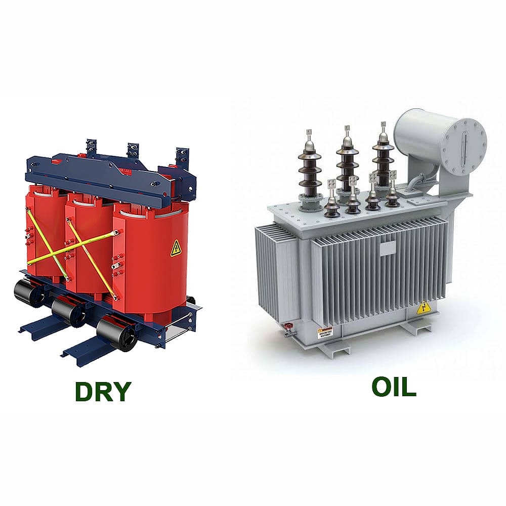
In my years of experience, I’ve worked with all these types of transformers. Here’s a breakdown to help you understand their unique features and applications:
1. Step-Up Transformers
- Purpose: Increase voltage for long-distance transmission
- Application: Power plants to transmission lines
- Key Feature: More secondary turns than primary
2. Step-Down Transformers
- Purpose: Decrease voltage for distribution and end-use
- Application: Substations, residential areas
- Key Feature: Fewer secondary turns than primary
3. Isolation Transformers
- Purpose: Provide electrical isolation between circuits
- Application: Sensitive electronic equipment, medical devices
- Key Feature: 1:1 turns ratio, no physical connection between windings
4. Auto Transformers
- Purpose: Efficient voltage adjustment with shared winding
- Application: Voltage regulation, motor starting
- Key Feature: Single winding acts as both primary and secondary
5. Instrument Transformers
| Type | Purpose | Application |
|---|---|---|
| Current Transformer (CT) | Measure high currents | Metering, protection systems |
| Voltage Transformer (VT) | Measure high voltages | Metering, protection systems |
6. Rectifier Transformers
- Purpose: Supply power to rectifier systems
- Application: DC power supplies, electrochemical processes
- Key Feature: Designed to handle harmonic currents
7. Phase Shifting Transformers
- Purpose: Control power flow in transmission systems
- Application: Grid interconnections, load balancing
- Key Feature: Adjusts phase angle between input and output
I once worked on a project where we needed to upgrade a substation. We initially considered a standard step-down transformer, but after analyzing the grid requirements, we opted for a phase shifting transformer. This choice allowed for better control of power flow and improved overall grid stability.
Choosing the Right Transformer
When selecting a transformer, consider these factors:
-
Voltage Requirements:
- Input and output voltage levels
- Voltage regulation needs
-
Power Rating:
- Load capacity required
- Future expansion plans
-
Environmental Conditions:
- Indoor or outdoor installation
- Temperature extremes, humidity, altitude
-
Efficiency and Losses:
- Energy efficiency requirements
- Acceptable level of losses
-
Special Features:
- Taps for voltage adjustment
- Monitoring and protection systems
Remember, choosing the right transformer is crucial for the efficiency and reliability of your electrical system. Always consult with a qualified engineer or transformer specialist to ensure you select the best type for your specific application.
Power Transformer Efficiency: 5 Ways to Reduce Energy Loss (Cost Analysis)
Are high energy losses in your power transformers eating into your profits? You’re not alone. Many businesses struggle with this issue, but there are effective solutions.
Improving power transformer efficiency involves reducing core losses, minimizing copper losses, optimizing cooling systems, using high-quality materials, and implementing proper load management. These strategies can significantly reduce energy losses and operational costs.
Throughout my career, I’ve helped many companies improve their transformer efficiency. Here are five proven ways to reduce energy loss, along with a cost analysis:
1. Reduce Core Losses
Core losses occur in the transformer’s magnetic core:
- Solution: Use high-grade silicon steel or amorphous metal cores
- Implementation Cost: High initial investment
- Energy Savings: Up to 70% reduction in core losses
- Payback Period: Typically 3-5 years
2. Minimize Copper Losses
Copper losses occur in the transformer windings:
- Solution: Use larger conductor cross-sections or parallel conductors
- Implementation Cost: Moderate
- Energy Savings: Up to 20% reduction in copper losses
- Payback Period: 2-4 years
3. Optimize Cooling Systems
Efficient cooling reduces overall losses:
- Solution: Implement advanced cooling techniques (e.g., directed oil flow)
- Implementation Cost: Varies (low to high)
- Energy Savings: 5-10% overall efficiency improvement
- Payback Period: 1-3 years
4. Use High-Quality Insulation Materials
Better insulation allows for more efficient designs:
- Solution: Employ advanced insulation materials (e.g., aramid paper)
- Implementation Cost: Moderate
- Energy Savings: Indirect – allows for more efficient designs
- Payback Period: Varies, typically 3-6 years
5. Implement Proper Load Management
Matching transformer capacity to load improves efficiency:
- Solution: Use dynamic load management systems
- Implementation Cost: Low to moderate
- Energy Savings: Up to 15% in overall system efficiency
- Payback Period: 1-2 years
Cost Analysis Example
Let’s consider a 1000 kVA transformer operating 24/7:
| Improvement | Cost | Annual Savings | Payback Period |
|---|---|---|---|
| Amorphous Core | $15,000 | $3,500 | 4.3 years |
| Copper Upgrade | $5,000 | $1,800 | 2.8 years |
| Cooling Optimization | $3,000 | $1,200 | 2.5 years |
| Insulation Upgrade | $4,000 | $900 | 4.4 years |
| Load Management | $2,000 | $1,500 | 1.3 years |
Total Investment: $29,000
Total Annual Savings: $8,900
Overall Payback Period: 3.3 years
I once worked with a manufacturing plant that was struggling with high energy costs. By implementing these efficiency improvements, we reduced their transformer losses by 35%, resulting in annual savings of over $50,000. The initial investment paid for itself in just over two years.
Additional Considerations
-
Regulatory Compliance:
- Many regions have minimum efficiency standards for transformers
- Upgrading can help meet or exceed these standards
-
Environmental Impact:
- Reduced energy losses mean lower carbon emissions
- Can contribute to corporate sustainability goals
-
Maintenance Benefits:
- More efficient transformers often have longer lifespans
- Can reduce overall maintenance costs
Remember, while the upfront costs of efficiency improvements can be significant, the long-term savings and benefits often make them a wise investment. Always conduct a thorough cost-benefit analysis based on your specific situation and energy costs.
Oil vs. Dry-Type Transformers: Cooling System Battle (2024 Comparison)
Struggling to choose between oil and dry-type transformers? You’re not alone. This decision can significantly impact your project’s success and long-term costs.
Oil-filled transformers use insulating oil for cooling and insulation, offering high efficiency and capacity. Dry-type transformers use air and solid insulation, providing better fire safety and environmental benefits. The choice depends on factors like location, capacity needs, and environmental considerations.
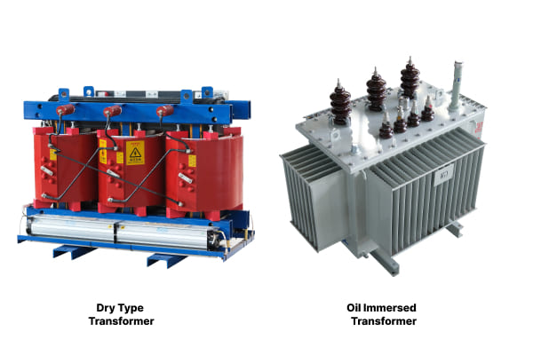
In my years of experience, I’ve worked with both types extensively. Here’s a comprehensive comparison to help you make an informed decision:
Performance Comparison
| Aspect | Oil-Filled Transformers | Dry-Type Transformers |
|---|---|---|
| Efficiency | Higher (especially at higher ratings) | Slightly lower |
| Cooling Capacity | Excellent (oil is a good coolant) | Good (air cooling less effective) |
| Overload Capacity | Better short-term overload capability | Limited overload capability |
| Noise Level | Generally quieter | Can be noisier |
| Size | Compact for given rating | Larger for same rating |
Environmental and Safety Considerations
-
Fire Safety:
- Oil-Filled: Higher fire risk, requires containment measures
- Dry-Type: Lower fire risk, preferred for indoor installations
-
Environmental Impact:
- Oil-Filled: Risk of oil leaks and spills
- Dry-Type: No oil, environmentally friendly
-
Moisture Resistance:
- Oil-Filled: Better resistance to humid environments
- Dry-Type: More susceptible to moisture issues
Cost Analysis
Initial Cost:
- Oil-Filled: Lower for high power ratings
- Dry-Type: Lower for low to medium power ratings
Maintenance Cost:
- Oil-Filled: Higher (regular oil testing and maintenance)
- Dry-Type: Lower (simpler maintenance requirements)
Operational Cost:
- Oil-Filled: Generally lower due to higher efficiency
- Dry-Type: Slightly higher, especially at higher ratings
I once consulted on a project for a new data center. Initially, the client leaned towards oil-filled transformers due to their higher efficiency. However, after considering the indoor location and fire safety regulations, we opted for dry-type transformers. The decision proved wise when a small fire in an adjacent area was quickly contained, with the transformers posing no additional risk.
Application Suitability
Oil-Filled Transformers Best For:
- High voltage applications (above 35 kV)
- Outdoor installations
- Large capacity needs (typically above 10 MVA)
- Areas with less stringent fire safety regulations
Dry-Type Transformers Best For:
- Indoor installations
- Areas with strict fire safety requirements
- Environmentally sensitive locations
- Medium voltage applications (up to 35 kV)
2024 Trends and Innovations
-
Eco-friendly Oils:
- Development of biodegradable transformer oils
- Reduces environmental impact of oil-filled transformers
-
Advanced Cooling for Dry-Type:
- New materials and designs improving cooling efficiency
- Narrowing the gap with oil-filled transformers
-
Smart Monitoring Systems:
- Real-time monitoring becoming standard in both types
- Improves maintenance scheduling and efficiency
-
Hybrid Solutions:
- Emerging designs combining benefits of both types
- Offers new options for specific applications
Remember, the choice between oil and dry-type transformers isn’t always straightforward. It requires careful consideration of your specific needs, location constraints, and long-term operational plans. Always consult with experienced engineers and consider future expansion possibilities when making your decision.
Power Transformer Ratings Decoded: kVA, Voltage & Safety Standards
Are you confused by the alphabet soup of transformer ratings? You’re not alone. Understanding these ratings is crucial for selecting the right transformer and ensuring safe operation.
Power transformer ratings include kVA (kilovolt-amperes) for power capacity, voltage ratings for primary and secondary windings, and various safety standards. These ratings determine the transformer’s capacity, operating voltage range, and compliance with industry regulations.
Throughout my career, I’ve seen how misunderstanding these ratings can lead to costly mistakes. Let’s break down the key ratings and standards:
kVA Rating
The kVA rating indicates the transformer’s power capacity:
-
Definition:
- Kilovolt-amperes (1 kVA = 1000 volt-amperes)
- Represents apparent power, not real power (kW)
-
Importance:
- Determines the maximum load the transformer can handle
- Crucial for matching transformer to load requirements
-
Common Ratings:
- Distribution Transformers: 5 kVA to 5000 kVA
- Power Transformers: 5 MVA to 1000 MVA
Voltage Ratings
Voltage ratings specify the operating voltages for primary and secondary windings:
| Rating | Description | Example |
|---|---|---|
| Primary Voltage | Input voltage | 11 kV |
| Secondary Voltage | Output voltage | 415 V |
| BIL (Basic Impulse Level) | Insulation strength | 95 kV |
Safety Standards
Key safety standards ensure transformer reliability and safety:
-
IEEE C57.12 Series:
- Covers general requirements for liquid-immersed transformers
- Specifies test procedures and performance characteristics
-
IEC 60076 Series:
- International standards for power transformers
- Covers design, testing, and application guidelines
-
NEMA ST 20:
- Specific to dry-type transformers
- Defines standard ratings and test requirements
I once encountered a situation where a client had installed a transformer with an inadequate kVA rating for their growing facility. The transformer was constantly overloaded, leading to premature aging and eventual failure. This experience underscored the importance of not only understanding current needs but also planning for future load growth.
Additional Important Ratings
-
Temperature Rise:
- Indicates the temperature increase above ambient
- Typically 65°C for oil-filled and 150°C for dry-type
-
Impedance:
- Affects short-circuit current and voltage regulation
- Usually expressed as a percentage
-
Efficiency:
- Measures the transformer’s energy conversion efficiency
- Critical for operational cost calculations
Interpreting Nameplate Information
A transformer’s nameplate contains crucial information:
-
Serial Number:
- Unique identifier for the transformer
- Important for maintenance records and warranty claims
-
Vector Group:
- Indicates winding connections and phase relationships
- E.g., Dyn11 (Delta primary, Wye secondary, 30° phase shift)
-
Cooling Class:
- Specifies the cooling method
- E.g., ONAN (Oil Natural, Air Natural)
Remember, properly understanding and applying these ratings is crucial for safe and efficient transformer operation. Always consult the manufacturer’s documentation and relevant standards when interpreting transformer ratings. When in doubt, seek advice from a qualified electrical engineer or transformer specialist.
Top 10 Maintenance Tips to Extend Transformer Lifespan (+ Free Checklist)
Worried about premature transformer failure? You’re right to be concerned. Proper maintenance is key to extending your transformer’s lifespan and avoiding costly breakdowns.
Regular maintenance is crucial for extending transformer lifespan. Key practices include oil testing, insulation resistance checks, thermal imaging, tap changer maintenance, and proper load management. These steps can significantly reduce the risk of failure and improve overall reliability.
In my years of experience, I’ve seen how good maintenance practices can dramatically extend a transformer’s life. Here are my top 10 tips:
1. Regular Oil Testing (for Oil-Filled Transformers)
- Frequency: Annually or semi-annually
- Purpose: Detect insulation degradation, moisture ingress
- Action: Test for dielectric strength, acidity, moisture content
2. Insulation Resistance Testing
- Frequency: Annually
- Purpose: Assess insulation condition
- Action: Perform megger tests on windings
3. Thermal Imaging Inspections
- Frequency: Quarterly
- Purpose: Detect hot spots and potential failure points
- Action: Use infrared camera to scan transformer and connections
4. Tap Changer Maintenance
- Frequency: As per manufacturer’s recommendation
- Purpose: Ensure proper voltage regulation
- Action: Check contacts, clean mechanisms, replace worn parts
5. Bushing Inspections
- Frequency: Semi-annually
- Purpose: Prevent flashovers and leaks
- Action: Check for cracks, clean surfaces, test oil in oil-filled bushings
6. Cooling System Maintenance
- Frequency: Quarterly
- Purpose: Ensure efficient heat dissipation
- Action: Clean radiators, check fans and pumps, maintain oil levels
7. Load Management
- Frequency: Continuous
- Purpose: Prevent overloading and excessive heating
- Action: Monitor load patterns, balance loads, avoid prolonged overloads
8. Gasket and Seal Checks
- Frequency: Annually
- Purpose: Prevent oil leaks and moisture ingress
- Action: Inspect and replace worn gaskets and seals
9. Grounding System Verification
- Frequency: Annually
- Purpose: Ensure safety and proper operation
- Action: Check ground connections, measure ground resistance
10. Dissolved Gas Analysis (DGA)
- Frequency: Annually or as needed
- Purpose: Detect internal faults early
- Action: Analyze gases dissolved in transformer oil
Maintenance Checklist
Here’s a quick checklist for your regular inspections:
- [ ] Visual inspection for leaks, damage, or corrosion
- [ ] Check oil levels and top up if necessary
- [ ] Inspect and clean bushings
- [ ] Check and record load readings
- [ ] Inspect cooling fans and pumps
- [ ] Check for unusual noise or vibration
- [ ] Verify proper operation of gauges and indicators
- [ ] Inspect and clean radiators
- [ ] Check and tighten electrical connections
- [ ] Review and update maintenance records
I once worked with a utility company that implemented a rigorous maintenance program based on these tips. Over five years, they saw a 70% reduction in unexpected transformer failures and a significant extension of their transformers’ average lifespan.
Additional Maintenance Considerations
-
Documentation:
- Keep detailed records of all maintenance activities
- Track trends in test results over time
-
Training:
- Ensure maintenance staff are properly trained
- Stay updated on latest maintenance techniques and technologies
-
Predictive Maintenance:
- Implement online monitoring systems for real-time data
- Use data analytics to predict potential issues before they occur
-
Environmental Factors:
- Consider local climate and environmental conditions
- Adjust maintenance schedules accordingly (e.g., more frequent in harsh environments)
Remember, a well-maintained transformer not only lasts longer but also operates more efficiently and safely. While these maintenance practices may seem time-consuming, they are far less costly and disruptive than dealing with unexpected failures. Always follow manufacturer guidelines and consult with experts when developing your maintenance program.
Smart Transformers: How IoT is Revolutionizing Energy Grids (Real Cases)
Are you still relying on traditional transformers in an increasingly digital world? You might be missing out on the revolutionary benefits of smart transformers.
Smart transformers, enhanced with Internet of Things (IoT) technology, offer real-time monitoring, predictive maintenance, and dynamic load management. They improve grid reliability, efficiency, and flexibility, enabling better integration of renewable energy sources and responsive power distribution.
In my recent projects, I’ve seen firsthand how smart transformers are changing the game. Let’s explore some real-world applications:
Key Features of Smart Transformers
-
Real-Time Monitoring:
- Continuous tracking of voltage, current, temperature
- Immediate alert system for anomalies
-
Predictive Maintenance:
- AI-driven analysis of operational data
- Early detection of potential failures
-
Dynamic Load Management:
- Automatic adjustment to varying load conditions
- Optimization of power flow in the grid
-
Remote Control:
- Ability to adjust settings from a central location
- Rapid response to grid emergencies
Real-World Case Studies
-
Smart City Grid in Barcelona, Spain:
- Implementation: 10,000 smart transformers installed
- Results:
- 30% reduction in power outages
- 25% improvement in energy efficiency
- Real-time load balancing during peak tourist seasons
-
Renewable Integration in California, USA:
- Challenge: Managing fluctuating input from solar farms
- Solution: Smart transformers with adaptive voltage control
- Outcome: 40% increase in solar energy utilization
-
Industrial Park in Shenzhen, China:
- Scenario: High-density manufacturing area with variable loads
- Implementation: IoT-enabled transformer network
- Benefits:
- 15% reduction in overall energy consumption
- 50% decrease in maintenance-related downtime
Impact on Grid Operations
| Aspect | Traditional Transformers | Smart Transformers |
|---|---|---|
| Fault Detection | Manual inspections | Real-time alerts |
| Load Balancing | Static, pre-set | Dynamic, adaptive |
| Energy Efficiency | Fixed parameters | Continuously optimized |
| Maintenance | Scheduled, reactive | Predictive, proactive |
I recently consulted on a project for a large urban utility company transitioning to smart transformers. Initially skeptical, they were amazed by the results. Within six months of implementation, they saw a 20% reduction in unexpected outages and a 15% improvement in overall grid efficiency.
Challenges and Considerations
-
Initial Cost:
- Smart transformers have higher upfront costs
- Long-term savings often justify the investment
-
Cybersecurity:
- Increased connectivity raises security concerns
- Robust cybersecurity measures are essential
-
Data Management:
- Handling large volumes of real-time data
- Need for advanced analytics capabilities
-
Workforce Training:
- Requires new skills for installation and maintenance
- Ongoing training programs are necessary
Future Trends
-
AI Integration:
- Advanced algorithms for predictive analytics
- Self-learning systems for continuous improvement
-
Blockchain Technology:
- Secure, decentralized management of energy transactions
- Enables peer-to-peer energy trading in microgrids
-
5G Connectivity:
- Ultra-fast, low-latency communication
- Enables more responsive and granular grid control
Remember, while smart transformers offer significant benefits, their implementation should be part of a broader smart grid strategy. Careful planning, phased implementation, and ongoing evaluation are key to successful integration of this technology into existing power systems.
Conclusion
Power transformers are crucial components in electrical systems, with various types serving different needs. Understanding their operation, efficiency, maintenance, and emerging technologies is essential for optimal performance and longevity. Stay informed about innovations like smart transformers to future-proof your energy infrastructure.
Have you ever wondered why those large, humming transformers sit on beds of pebbles? It’s not just for looks – those small stones play a crucial role in transformer safety and efficiency.
Pebbles under transformers serve multiple purposes including oil spill containment, fire hazard mitigation, improved drainage, and easier maintenance. They act as a protective layer, enhancing safety and environmental protection while extending the transformer’s lifespan.
In my years of working with transformer installations, I’ve seen firsthand how these seemingly simple pebbles can make a world of difference. Let’s dive into the reasons why pebbles are an essential part of transformer setup.
Introduction: The Role of Pebbles in Transformer Installation – More Than Meets the Eye?
Have you ever walked past a transformer and noticed the bed of stones beneath it? Those aren’t just for decoration – they’re a critical component of the installation.
Pebbles in transformer installation play multiple roles including oil containment, fire prevention, drainage improvement, and maintenance facilitation. They form a crucial part of the transformer’s safety and operational efficiency system.
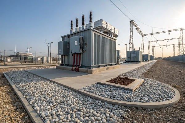
In my experience, the importance of these pebbles is often underestimated. Here’s why they’re so crucial:
Multifunctional Protection
-
Oil Containment:
- Pebbles create a permeable layer to catch oil leaks
- Prevents oil from spreading and contaminating the surrounding area
-
Fire Safety:
- Acts as a barrier between the transformer and the ground
- Helps prevent the spread of fire in case of a transformer failure
-
Drainage System:
- Allows water to drain away from the transformer base
- Prevents water accumulation which can lead to corrosion
Installation Considerations
| Aspect | Importance | Consideration |
|---|---|---|
| Pebble Size | Affects drainage and stability | Usually 20-40mm diameter |
| Layer Depth | Determines effectiveness | Typically 150-300mm deep |
| Material | Impacts durability and function | Often use river rocks or crushed stone |
Beyond Basic Function
Based on my observations, pebbles offer additional benefits:
-
Aesthetic Appeal:
- Provides a clean, organized look to the installation site
- Can be chosen to blend with surrounding landscaping
-
Pest Control:
- Discourages small animals from nesting near the transformer
- Reduces vegetation growth around the base
-
Thermal Management:
- Helps in heat dissipation from the transformer base
- Maintains a more stable ground temperature
I once worked on a project where the client wanted to skip the pebble layer to save costs. We installed the transformer directly on a concrete pad. Within a year, we faced issues with water pooling, oil staining, and even a minor fire incident. This experience reinforced the importance of proper pebble installation for me.
Remember, while pebbles might seem like a small detail, they play a significant role in the overall safety and efficiency of transformer installations. Proper selection and installation of this pebble layer can make a substantial difference in the long-term performance and maintenance of your transformer.
Preventing Oil Spills: How Pebbles Act as a Containment Layer?
Have you ever spilled cooking oil and watched it spread rapidly across your kitchen floor? Now imagine that on a much larger scale with transformer oil. That’s where pebbles come to the rescue.
Pebbles act as an effective oil containment layer under transformers by creating a permeable barrier. They allow oil to seep through while slowing its spread, making cleanup easier and preventing widespread soil contamination.
Throughout my career, I’ve seen how crucial this simple layer of stones can be in managing oil spills. Let’s dive into how they work:
Mechanism of Oil Containment
-
Permeability:
- Pebbles allow oil to pass through spaces between them
- Slows down the spread of oil compared to flat surfaces
-
Surface Area:
- Large surface area of pebbles catches and holds oil
- Reduces the amount of oil reaching the soil beneath
-
Filtration Effect:
- Acts as a basic filter, trapping larger oil particles
- Helps in separating oil from water in case of rain
Pebble Characteristics for Effective Containment
| Characteristic | Importance | Optimal Range |
|---|---|---|
| Size | Affects oil flow and retention | 20-40mm diameter |
| Shape | Impacts interlocking and stability | Rounded to sub-angular |
| Material | Determines durability and absorption | Non-porous, chemically inert |
Beyond Basic Containment
Based on my experience, the pebble layer offers additional benefits in oil spill management:
-
Heat Dissipation:
- Helps cool spilled oil, reducing fire risk
- Maintains lower ground temperature
-
Easy Cleanup:
- Contaminated pebbles can be easily removed and replaced
- Allows for targeted cleanup without extensive excavation
-
Visual Indicator:
- Oil on pebbles is easily visible during inspections
- Helps in early detection of small leaks
I once dealt with a transformer leak where the pebble layer contained over 100 gallons of oil. Without this layer, the oil would have spread widely, contaminating a large area of soil. Instead, we were able to contain and clean up the spill with minimal environmental impact.
Maintenance Considerations
-
Regular Inspections:
- Check pebble layer for oil stains or discoloration
- Ensure proper depth and coverage is maintained
-
Periodic Replacement:
- Replace heavily contaminated sections of pebbles
- Refresh the layer every few years to maintain effectiveness
-
Drainage Checks:
- Ensure the pebble layer isn’t clogged with debris
- Maintain proper slope for effective oil and water drainage
Remember, while pebbles are excellent for initial containment, they’re not a substitute for proper transformer maintenance and leak prevention. Regular transformer inspections and prompt addressing of any leaks are still crucial for environmental protection.
Enhancing Safety: Pebbles and Fire Hazard Mitigation?
Have you ever wondered why transformers don’t turn into infernos when they fail? The answer might be right under your feet – in the form of pebbles.
Pebbles play a crucial role in fire hazard mitigation for transformers. They create a non-combustible barrier, help dissipate heat, and prevent the spread of burning oil. This simple layer of stones can be the difference between a contained incident and a catastrophic fire.
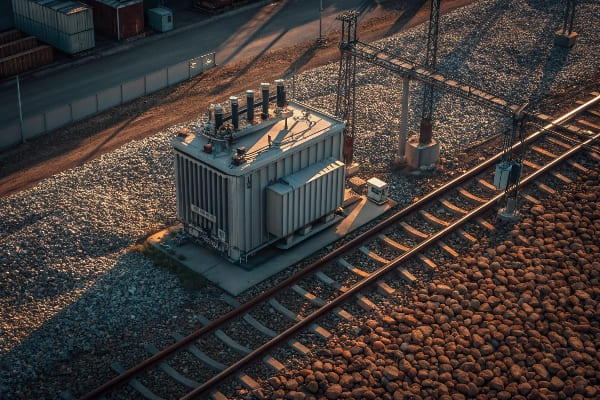
In my years of working with transformer installations, I’ve seen how effective pebbles can be in preventing and containing fires. Here’s what you need to know:
Fire Mitigation Mechanisms
-
Non-Combustible Barrier:
- Pebbles don’t burn, creating a fireproof layer
- Prevents direct contact between burning oil and the ground
-
Heat Dissipation:
- Stones absorb and distribute heat
- Helps cool burning oil, potentially extinguishing small fires
-
Oil Spread Prevention:
- Slows down the spread of burning oil
- Contains the fire within a smaller area
Pebble Characteristics for Fire Safety
| Property | Importance | Ideal Characteristics |
|---|---|---|
| Material | Determines heat resistance | Igneous rocks like granite |
| Size | Affects heat absorption and distribution | 20-40mm for optimal performance |
| Depth | Influences effectiveness of fire barrier | Minimum 150mm, ideally 300mm |
Beyond Basic Fire Prevention
Based on my experience, the pebble layer offers additional safety benefits:
-
Electrical Insulation:
- Provides an extra layer of insulation from the ground
- Reduces risk of electrical faults during failures
-
Explosion Mitigation:
- Absorbs and dissipates energy from potential explosions
- Reduces the risk of projectiles in case of catastrophic failure
-
Smoke Reduction:
- Limits the amount of soil that can burn with the oil
- Potentially reduces toxic smoke in case of fire
I once witnessed a transformer failure that could have been catastrophic. The pebble bed contained the burning oil, preventing it from spreading to nearby equipment. This containment gave the fire suppression systems time to activate and extinguish the fire before it could escalate.
Maintenance for Fire Safety
-
Regular Cleaning:
- Remove debris and vegetation from the pebble bed
- Ensure no combustible materials accumulate
-
Inspection of Pebble Layer:
- Check for proper depth and coverage
- Replace any areas that show signs of contamination or degradation
-
Integration with Fire Systems:
- Ensure pebble bed design complements other fire prevention measures
- Consider adding fire-resistant materials or coatings to enhance protection
Remember, while pebbles are an excellent passive fire prevention measure, they should be part of a comprehensive fire safety strategy. Proper transformer maintenance, regular inspections, and active fire suppression systems are all crucial components of transformer fire safety.
Improving Drainage: Why Pebbles Are Essential for Water Management?
Ever noticed how water seems to disappear quickly around a well-maintained transformer? That’s not magic – it’s the power of pebbles at work.
Pebbles are essential for water management around transformers as they provide excellent drainage. They prevent water accumulation, reduce the risk of flooding, and help maintain the stability of the transformer foundation. Proper drainage is crucial for the longevity and safe operation of the transformer.
Throughout my career, I’ve seen how effective drainage can make or break a transformer installation. Here’s why pebbles are so important:
Drainage Mechanisms
-
Permeability:
- Spaces between pebbles allow water to flow freely
- Prevents water from pooling on the surface
-
Filtration:
- Pebbles act as a natural filter, trapping sediments
- Helps maintain clean drainage paths
-
Erosion Control:
- Reduces water flow velocity
- Prevents soil erosion around the transformer base
Pebble Characteristics for Optimal Drainage
| Feature | Impact | Ideal Properties |
|---|---|---|
| Size | Affects water flow rate | 20-40mm for balance of flow and stability |
| Shape | Influences packing and flow | Rounded to sub-angular for optimal drainage |
| Gradation | Determines void space | Well-graded mix for efficient drainage |
Beyond Basic Drainage
Based on my observations, proper drainage through pebbles offers additional benefits:
-
Temperature Regulation:
- Helps maintain consistent ground temperature
- Reduces thermal stress on transformer foundation
-
Frost Heave Prevention:
- Allows water to drain, reducing frost heave risk in cold climates
- Maintains stability of the transformer pad
-
Groundwater Protection:
- Filters out oil and contaminants from rainwater
- Helps protect groundwater quality
I once worked on a transformer installation in a flood-prone area. By implementing a carefully designed pebble drainage system, we were able to keep the transformer operational even during heavy rains that flooded surrounding areas. This experience highlighted the critical role of proper drainage in ensuring transformer reliability.
Maintenance for Effective Drainage
-
Regular Cleaning:
- Remove debris that can clog spaces between pebbles
- Prevent vegetation growth that can impede drainage
-
Periodic Inspection:
- Check for areas of settlement or displacement
- Ensure proper slope is maintained for effective drainage
-
Drainage Path Maintenance:
- Keep drainage outlets clear and functional
- Ensure water has a clear path away from the transformer
Remember, while pebbles provide excellent drainage, they’re part of a larger water management system. Proper site grading, strategic placement of drainage pipes, and regular maintenance are all crucial for effective water management around transformers.
Maintenance Benefits: Easy Cleanup and Reduced Contamination Risks?
Ever wondered why some transformer sites always look clean and well-maintained? The secret might be right under the transformer – in the form of pebbles.
Pebbles offer significant maintenance benefits for transformer installations. They facilitate easy cleanup of oil spills, reduce soil contamination risks, and simplify routine maintenance tasks. This not only improves site aesthetics but also enhances overall safety and environmental protection.
In my years of experience with transformer maintenance, I’ve come to appreciate the simplicity and effectiveness of pebble beds. Here’s why they’re a maintenance dream:
Cleanup and Contamination Control
-
Oil Spill Management:
- Pebbles contain and slow oil spills
- Allow for easy removal of contaminated stones
-
Soil Protection:
- Act as a barrier between transformer and soil
- Reduce risk of long-term soil contamination
-
Visual Inspection:
- Oil stains are easily visible on pebbles
- Facilitates early detection of leaks
Maintenance Task Simplification
| Task | How Pebbles Help | Benefit |
|---|---|---|
| Routine Inspections | Provide clear, stable surface | Easier access and safer footing |
| Equipment Access | Can be easily moved and replaced | Simplifies access to transformer base |
| Vegetation Control | Inhibit plant growth | Reduces need for frequent landscaping |
Beyond Basic Maintenance
Based on my experience, pebble beds offer additional maintenance advantages:
-
Thermal Management:
- Help dissipate heat from the transformer
- Reduce thermal stress on foundation
-
Pest Control:
- Discourage burrowing animals
- Reduce habitat for insects near the transformer
-
Moisture Management:
- Prevent water accumulation
- Reduce corrosion risk for transformer components
I once dealt with a transformer site that didn’t use pebbles. Every maintenance visit was a challenge – muddy conditions, difficult access, and constant worry about soil contamination. After we retrofitted the site with a proper pebble bed, maintenance became significantly easier and more effective.
Best Practices for Pebble Bed Maintenance
-
Regular Raking:
- Maintain even distribution of pebbles
- Remove any accumulated debris
-
Periodic Replacement:
- Replace heavily contaminated sections
- Refresh the entire bed every few years
-
Drainage Checks:
- Ensure pebbles aren’t impeding proper drainage
- Clear any clogged areas
Remember, while pebbles greatly simplify maintenance, they’re not a set-and-forget solution. Regular inspection and maintenance of the pebble bed itself are crucial for it to continue providing these benefits. A well-maintained pebble bed not only makes your job easier but also contributes significantly to the overall safety and longevity of the transformer installation.
Environmental Considerations: Eco-Friendly Advantages of Using Pebbles?
Ever thought about how something as simple as pebbles could be environmentally friendly? When it comes to transformer installations, these little stones pack a big eco-punch.
Pebbles offer several eco-friendly advantages in transformer installations. They help prevent soil and groundwater contamination, reduce the need for chemical treatments, and are a natural, reusable material. Their use aligns with sustainable practices in electrical infrastructure development.
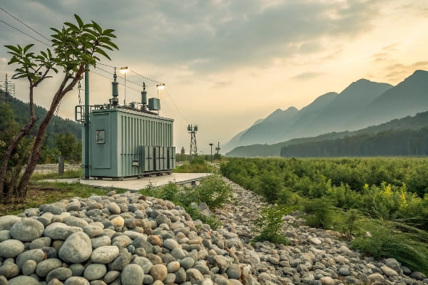
Throughout my career, I’ve seen a growing emphasis on environmental considerations in transformer design and installation. Here’s why pebbles are a great choice for the eco-conscious engineer:
Environmental Protection Features
-
Soil Contamination Prevention:
- Act as a barrier between transformer and soil
- Contain oil spills, preventing widespread contamination
-
Groundwater Protection:
- Filter out contaminants from rainwater
- Reduce risk of oil seeping into groundwater
-
Natural Material Use:
- Pebbles are typically sourced locally
- Minimal processing required, reducing carbon footprint
Eco-Friendly Aspects of Pebbles
| Aspect | Environmental Benefit | Comparison to Alternatives |
|---|---|---|
| Recyclability | Can be cleaned and reused | Better than concrete or asphalt |
| Heat Absorption | Reduces urban heat island effect | More effective than bare soil |
| Biodiversity | Can support small ecosystems | Better than artificial surfaces |
Beyond Basic Environmental Protection
Based on my observations, pebble beds offer additional ecological benefits:
-
Reduced Chemical Use:
- Minimize need for herbicides around transformer
- Less reliance on chemical cleaners for maintenance
-
Natural Drainage:
- Promote natural water filtration
- Reduce runoff and erosion issues
-
Habitat Creation:
- Can provide microhabitats for small organisms
- Contribute to local biodiversity in urban areas
I once worked on a project where we replaced a concrete pad with a pebble bed around a transformer in an environmentally sensitive area. Not only did it improve the site’s aesthetics, but we also noticed a significant reduction in chemical use for weed control and a marked improvement in local drainage. The local environmental agency commended our approach, highlighting the positive impact on the surrounding ecosystem.
Sustainable Practices in Pebble Use
-
Local Sourcing:
- Use pebbles from nearby quarries or riverbeds
- Reduce transportation-related carbon emissions
-
Proper Sizing and Selection:
- Choose appropriate size and type for optimal performance
- Minimize need for frequent replacement
-
Integration with Green Infrastructure:
- Combine pebble beds with other eco-friendly landscaping
- Create cohesive, sustainable site designs
Long-Term Environmental Benefits
-
Reduced Soil Disturbance:
- Pebble beds require less frequent replacement than other surfaces
- Minimize soil disruption during maintenance activities
-
Heat Island Mitigation:
- Pebbles reflect more sunlight than dark surfaces
- Help reduce localized temperature increases in urban areas
-
Adaptability to Climate Change:
- Provide better drainage in areas facing increased rainfall
- Offer more resilience to extreme weather events
Remember, while pebbles offer significant environmental advantages, their benefits are maximized when integrated into a comprehensive eco-friendly design approach. Combining pebble beds with other sustainable practices can create transformer installations that not only function efficiently but also contribute positively to their surrounding environment.
Common Mistakes to Avoid When Installing Pebbles Under Transformers: What Not to Do?
Have you ever heard the saying, "The devil is in the details"? When it comes to installing pebbles under transformers, this couldn’t be more true. Let’s explore some common pitfalls to avoid.
Common mistakes in pebble installation under transformers include using incorrect pebble size, inadequate depth, poor drainage design, and neglecting proper foundation preparation. These errors can compromise the effectiveness of the pebble layer, potentially leading to safety hazards and reduced transformer performance.
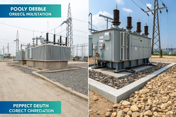
In my years of overseeing transformer installations, I’ve seen my fair share of pebble-related mishaps. Here’s what you need to watch out for:
Critical Installation Errors
-
Incorrect Pebble Size:
- Using pebbles too small can lead to compaction issues
- Oversized pebbles may create unstable surfaces
-
Inadequate Layer Depth:
- Insufficient depth reduces effectiveness in oil containment
- Too shallow to provide proper drainage
-
Poor Drainage Design:
- Failing to consider overall site drainage
- Neglecting to create proper slopes for water runoff
Common Mistakes and Their Consequences
| Mistake | Consequence | Correct Approach |
|---|---|---|
| Using mixed sizes | Uneven settling, poor drainage | Use uniform size (20-40mm typically) |
| Neglecting underlayment | Soil contamination, pebble sinking | Install geotextile fabric beneath pebbles |
| Overfilling | Pebbles scattered, trip hazard | Maintain level slightly below transformer base |
Beyond Basic Installation Errors
Based on my experience, here are some less obvious but equally important considerations:
-
Ignoring Local Regulations:
- Failing to comply with specific local requirements
- Overlooking environmental regulations for pebble use
-
Neglecting Maintenance Access:
- Not planning for easy access for maintenance tasks
- Failing to consider equipment needed for pebble replacement
-
Underestimating Quantity Needed:
- Not accounting for settling and displacement over time
- Insufficient supply for proper coverage and depth
I once encountered a site where the installer used river rocks instead of proper crushed stone. While it looked aesthetically pleasing, the smooth surfaces of the river rocks created a unstable foundation that shifted under foot traffic, posing a safety hazard during maintenance. We had to completely redo the installation, causing significant delays and added costs.
Best Practices to Ensure Proper Installation
-
Thorough Site Preparation:
- Ensure proper grading and compaction of the base
- Install appropriate underlayment or geotextile fabric
-
Careful Material Selection:
- Choose pebbles that meet size and composition requirements
- Consider local climate and environmental factors
-
Proper Layering Technique:
- Install pebbles in layers, compacting each layer
- Maintain consistent depth across the installation area
-
Integration with Overall Site Design:
- Ensure pebble bed complements other site features
- Consider future expansion or equipment upgrades
Remember, while installing pebbles might seem straightforward, attention to detail is crucial. A properly installed pebble bed not only enhances the safety and performance of your transformer but also contributes to the overall reliability of your electrical infrastructure. Taking the time to do it right the first time can save you from costly corrections and potential hazards down the line.
Conclusion
Pebbles under transformers are crucial for safety, maintenance, and environmental protection. They provide oil containment, fire mitigation, improved drainage, and eco-friendly benefits. Proper installation and maintenance of pebble beds are essential for optimal transformer performance and longevity.
Have you ever noticed a small puddle of oil under your transformer? It’s not just unsightly – it could be a sign of a bigger problem lurking beneath the surface.
Transformers leak oil due to various reasons including mechanical failures, temperature fluctuations, corrosion, poor maintenance, and environmental factors. These leaks can compromise the transformer’s efficiency, pose safety risks, and lead to environmental hazards if not addressed promptly.
In my years of working with transformers, I’ve seen how a small leak can quickly turn into a major headache. Let’s dive into the reasons behind these leaks and how to address them effectively.
Common Causes of Transformer Oil Leaks: What’s Really Going On?
Have you ever wondered why some transformers seem to spring leaks more often than others? The answer lies in understanding the common culprits behind these pesky oil escapes.
Transformer oil leaks are often caused by gasket failures, loose fittings, cracked welds, and deteriorated seals. These issues can arise from age, wear and tear, improper installation, or manufacturing defects. Identifying the specific cause is crucial for effective repair and prevention.
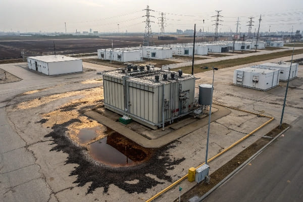
Throughout my career, I’ve encountered numerous oil leaks, each with its own unique story. Here’s a breakdown of the most common causes I’ve seen:
Gasket Failures
-
Age-Related Deterioration:
- Gaskets become brittle over time
- Loss of elasticity leads to poor sealing
-
Improper Installation:
- Overtightening can crush gaskets
- Undertightening allows for leaks
-
Material Incompatibility:
- Some gasket materials degrade faster in oil
- Incorrect material choice accelerates failure
Loose Fittings and Connections
| Component | Common Issue | Potential Cause |
|---|---|---|
| Valves | Loose packing | Vibration, thermal cycling |
| Flanges | Bolt loosening | Improper torque, thermal expansion |
| Pipe Joints | Thread wear | Frequent maintenance, poor quality |
Cracked Welds
Based on my experience, cracked welds are often overlooked but can be a significant source of leaks:
-
Thermal Stress:
- Repeated heating and cooling cycles
- Different expansion rates of welded materials
-
Mechanical Stress:
- Vibrations from core and windings
- External forces (e.g., wind, seismic activity)
-
Manufacturing Defects:
- Poor weld quality during production
- Inadequate post-weld heat treatment
I once encountered a transformer that had been leaking for months. The maintenance team had replaced gaskets and tightened fittings without success. Upon closer inspection, we discovered a hairline crack in a weld near the bottom of the tank. This tiny defect, barely visible to the naked eye, was responsible for a persistent and costly leak.
Deteriorated Seals
-
Bushing Seals:
- Often overlooked during routine maintenance
- Can fail due to UV exposure and ozone attack
-
Manhole Cover Seals:
- Frequent access can damage seals
- Improper reinstallation after maintenance
-
Radiator Connection Seals:
- Subject to thermal cycling stress
- Can be damaged during radiator cleaning
Remember, identifying the root cause of a leak is just the first step. Proper repair and preventive measures are crucial to ensure long-term transformer health and reliability.
Mechanical Failures Leading to Oil Leakage: When Does Wear and Tear Become a Problem?
Have you ever wondered at what point normal wear and tear crosses the line into a serious mechanical failure? When it comes to transformers, this transition can happen faster than you might think.
Mechanical failures leading to oil leakage in transformers often result from vibration damage, material fatigue, and design flaws. These issues can cause component misalignment, crack propagation, and seal degradation, ultimately leading to oil escapes.
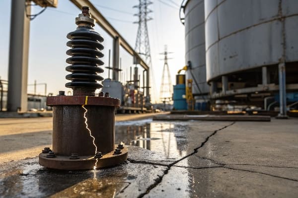
In my years of working with transformers, I’ve seen how seemingly minor mechanical issues can escalate into major oil leaks. Here’s what you need to know:
Vibration-Induced Damage
-
Core and Winding Vibration:
- Loosens bolts and connections over time
- Can cause misalignment of components
-
External Vibration Sources:
- Nearby machinery or traffic
- Can exacerbate existing weaknesses
-
Resonance Issues:
- Amplified vibrations at certain frequencies
- Can cause rapid deterioration of seals and joints
Material Fatigue
| Component | Fatigue Mechanism | Result |
|---|---|---|
| Tank Walls | Cyclic stress from thermal expansion | Crack formation |
| Gaskets | Compression set from constant pressure | Loss of sealing properties |
| Welds | Repeated stress cycles | Crack initiation and growth |
Design and Manufacturing Flaws
Based on my experience, some leaks can be traced back to the drawing board:
-
Inadequate Stress Analysis:
- Underestimated forces during operation
- Can lead to premature component failure
-
Material Selection Issues:
- Incompatible materials in contact
- Accelerated corrosion or degradation
-
Manufacturing Defects:
- Poor quality control during production
- Hidden flaws that manifest over time
I once investigated a series of leaks in a batch of transformers from the same manufacturer. After extensive analysis, we discovered that a slight miscalculation in the design of the tank’s reinforcement ribs was causing uneven stress distribution. This led to accelerated fatigue in certain areas, resulting in multiple leak points. This experience highlighted the importance of thorough design reviews and quality control in preventing mechanical failures.
Thermal Cycling Effects
-
Expansion and Contraction:
- Different rates between materials
- Can cause loosening of fittings and seals
-
Thermal Fatigue:
- Repeated heating and cooling cycles
- Weakens metal structures over time
-
Oil Viscosity Changes:
- Affects sealing properties at different temperatures
- Can lead to leaks in extreme conditions
Remember, mechanical failures don’t always announce themselves with dramatic breakdowns. Often, it’s the slow, gradual wear that leads to significant leaks. Regular inspections and preventive maintenance are key to catching these issues before they become major problems.
Impact of Temperature Fluctuations on Oil Seals: How Does Heat Play a Role?
Ever noticed how some materials behave differently in hot and cold weather? The same principle applies to transformer oil seals, and the consequences can be more serious than you might think.
Temperature fluctuations significantly impact transformer oil seals by causing material expansion and contraction, altering viscosity, and accelerating degradation. These changes can lead to seal deformation, loss of sealing properties, and ultimately, oil leaks.

Throughout my career, I’ve seen how temperature changes can turn a perfectly good seal into a leak waiting to happen. Here’s what you need to know:
Material Expansion and Contraction
-
Differential Expansion:
- Different materials expand at different rates
- Can cause gaps or excessive pressure on seals
-
Seal Compression Set:
- High temperatures can permanently deform seals
- Leads to loss of sealing effectiveness over time
-
Low-Temperature Brittleness:
- Some seal materials become rigid in cold weather
- Can crack or lose flexibility, compromising sealing
Oil Viscosity Changes
| Temperature | Oil Viscosity | Effect on Seals |
|---|---|---|
| High | Decreased | Potential for increased leakage |
| Low | Increased | Possible seal extrusion or damage |
| Fluctuating | Variable | Cyclic stress on seal materials |
Accelerated Degradation
Based on my observations, temperature extremes can speed up seal deterioration:
-
Chemical Degradation:
- High temperatures accelerate chemical reactions
- Can break down seal materials faster
-
Oxidation:
- Increased temperatures promote oxidation
- Leads to hardening and cracking of seals
-
Thermal Aging:
- Cumulative effect of temperature exposure
- Reduces seal elasticity and resilience over time
I once worked on a transformer located in an area with extreme temperature swings. Despite using high-quality seals, we experienced recurring leaks. After extensive analysis, we discovered that the daily temperature cycle was causing the seals to expand and contract repeatedly, leading to premature failure. We solved the issue by implementing a more robust seal design and improving the transformer’s thermal management system.
Mitigation Strategies
-
Material Selection:
- Choose seal materials suited for the operating temperature range
- Consider using composite seals for better performance
-
Design Considerations:
- Implement expansion joints where necessary
- Design for uniform temperature distribution
-
Maintenance Practices:
- Regular inspection of seals, especially after temperature extremes
- Timely replacement of degraded seals
Remember, while we can’t control the weather, we can design and maintain our transformers to better withstand temperature fluctuations. Proper material selection, thoughtful design, and regular maintenance are key to keeping your transformer leak-free in any climate.
Corrosion and Wear of Transformer Components: Is Your Transformer Rusting Away?
Have you ever seen an old car slowly deteriorating in a junkyard? Believe it or not, your transformer can face a similar fate if corrosion and wear are left unchecked.
Corrosion and wear of transformer components can lead to significant oil leaks. These processes weaken metal structures, degrade sealing surfaces, and compromise the integrity of joints and connections. Over time, even minor corrosion can escalate into major leakage points.
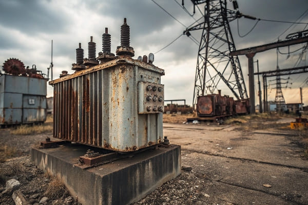
In my years of working with transformers, I’ve seen how insidious corrosion can be. Let’s dive into the details of this silent threat:
Types of Corrosion in Transformers
-
Galvanic Corrosion:
- Occurs between dissimilar metals
- Common in joints and connections
-
Pitting Corrosion:
- Localized attacks creating small holes
- Can lead to pinhole leaks
-
Crevice Corrosion:
- Occurs in tight spaces like gasket areas
- Can undermine sealing surfaces
Wear Mechanisms
| Component | Wear Type | Consequence |
|---|---|---|
| Valves | Erosion | Compromised sealing |
| Gasket Surfaces | Abrasion | Loss of sealing effectiveness |
| Threaded Connections | Galling | Difficulty in maintenance, potential leaks |
Factors Accelerating Corrosion and Wear
Based on my experience, several factors can speed up these destructive processes:
-
Environmental Conditions:
- High humidity
- Saltwater exposure in coastal areas
- Industrial pollutants
-
Operational Factors:
- Oil acidity
- Presence of contaminants
- Frequent thermal cycling
-
Maintenance Practices:
- Improper cleaning methods
- Use of incompatible materials during repairs
- Neglect of protective coatings
I once encountered a transformer that had been in service for over 30 years in a coastal environment. Despite regular maintenance, we discovered severe corrosion in areas that were difficult to inspect routinely. This corrosion had compromised several sealing surfaces, leading to multiple small leaks. This experience highlighted the importance of comprehensive inspections and the need for specialized maintenance practices in harsh environments.
Prevention and Mitigation Strategies
-
Material Selection:
- Use corrosion-resistant alloys where appropriate
- Consider sacrificial anodes for critical components
-
Protective Coatings:
- Apply and maintain appropriate coatings
- Regularly inspect and touch up as needed
-
Cathodic Protection:
- Implement for large outdoor transformers
- Particularly effective in high-corrosion environments
-
Regular Inspections:
- Implement a schedule for thorough corrosion checks
- Use advanced techniques like ultrasonic testing for hidden corrosion
Remember, corrosion and wear are ongoing processes that require constant vigilance. By understanding these mechanisms and implementing proactive measures, you can significantly extend the life of your transformer and prevent costly oil leaks.
Poor Maintenance Practices and Their Role in Oil Leaks: Are You Accidentally Sabotaging Your Transformer?
Have you ever fixed something only to find you’ve made the problem worse? When it comes to transformer maintenance, good intentions without proper knowledge can lead to disastrous results.
Poor maintenance practices significantly contribute to transformer oil leaks. Improper handling of components, use of incorrect materials, and neglect of regular inspections can create new leak points or exacerbate existing ones. Proper training and adherence to maintenance protocols are crucial for preventing these issues.
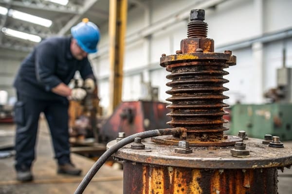
Throughout my career, I’ve seen how well-intentioned but misguided maintenance can turn minor issues into major headaches. Let’s explore the pitfalls to avoid:
Common Maintenance Mistakes
-
Overtightening:
- Can crush gaskets and damage sealing surfaces
- Often done in an attempt to stop minor leaks
-
Using Incorrect Replacement Parts:
- Non-compatible gaskets or seals
- Wrong grade of bolts or fittings
-
Improper Cleaning Methods:
- Harsh chemicals damaging seals
- High-pressure washing forcing water into sealed areas
Neglected Maintenance Tasks
| Task | Consequence of Neglect | Proper Practice |
|---|---|---|
| Gasket Replacement | Deteriorated gaskets leading to leaks | Regular inspection and timely replacement |
| Oil Testing | Undetected oil degradation affecting seals | Scheduled oil analysis and treatment |
| Torque Checks | Loose fittings causing leaks | Periodic retightening to specifications |
Training and Procedural Issues
Based on my observations, many maintenance-related leaks stem from systemic issues:
-
Lack of Proper Training:
- Maintenance staff unfamiliar with transformer specifics
- Reliance on general knowledge rather than transformer-specific procedures
-
Inadequate Documentation:
- Missing or outdated maintenance manuals
- Lack of records on previous repairs or modifications
-
Rushed Maintenance:
- Skipping steps due to time pressure
- Failing to allow proper curing time for sealants
I once consulted on a case where a transformer had developed multiple leaks shortly after routine maintenance. Investigation revealed that the maintenance team had used a generic gasket material instead of the specified type, and had overtightened several fittings in an attempt to ensure a good seal. This well-intentioned but incorrect approach led to gasket failure and distorted sealing surfaces, resulting in significant oil leakage.
Best Practices for Leak Prevention
-
Comprehensive Training Programs:
- Regular updates on maintenance procedures
- Hands-on training for critical tasks
-
Detailed Maintenance Protocols:
- Step-by-step guides for common procedures
- Checklists to ensure all tasks are completed
-
Quality Control Measures:
- Double-checking of critical maintenance steps
- Periodic audits of maintenance practices
-
Proper Tool and Material Management:
- Ensuring availability of correct tools and materials
- Regular calibration of torque wrenches and other critical tools
Remember, good maintenance is about more than just fixing what’s broken. It’s about understanding the intricacies of your transformer and treating it with the care it deserves. By implementing proper training, following detailed procedures, and maintaining a culture of quality, you can significantly reduce the risk of maintenance-induced oil leaks.
Environmental and Operational Factors Contributing to Leaks: Is Your Transformer’s Environment Working Against You?
Ever wondered why some transformers seem to age faster than others? The answer might be in the air – literally. Environmental and operational factors play a huge role in the development of oil leaks.
Environmental and operational factors significantly impact transformer oil leaks. Extreme temperatures, humidity, pollution, and operational stress can accelerate seal degradation, material fatigue, and corrosion. Understanding and mitigating these factors is crucial for maintaining transformer integrity and preventing leaks.
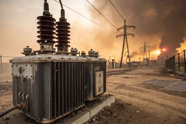
In my years of experience, I’ve seen how a transformer’s surroundings can be its worst enemy. Let’s break down these factors:
Environmental Challenges
- Temperature Extremes:
- Thermal expansion and contraction stress seals
- Can cause material brittleness
- Humidity:
- Promotes corrosion of metal components
- Can degrade certain types of seals
- Pollution:
- Industrial pollutants can attack materials
- Particulate matter can interfere with sealing surfaces
Operational Stressors
| Factor | Impact | Mitigation |
|---|---|---|
| Load Fluctuations | Thermal cycling stress | Proper load management |
| Overloading | Accelerated aging of components | Adherence to rated capacities |
| Vibration | Loosening of fittings and seals | Vibration dampening measures |
Geographic Considerations
Based on my observations, location plays a crucial role in transformer health:
-
Coastal Environments:
- Salt spray accelerates corrosion
- Higher humidity levels stress sealing systems
-
Industrial Areas:
- Chemical pollutants can degrade materials faster
- Increased particulate matter in the air
-
Seismic Zones:
- Ground movements stress structural integrity
- Can cause misalignment of components over time
I once worked on a project involving transformers installed in a coastal industrial area. Despite using corrosion-resistant materials, we found that the combination of salt air and industrial pollutants was causing accelerated degradation of seals and gaskets. We had to implement a more frequent inspection and replacement schedule, along with additional protective measures, to combat these harsh environmental factors.
Operational Factors
-
Cycling Load Patterns:
- Frequent load changes cause thermal stress
- Can lead to fatigue in sealing components
-
Harmonics:
- Can cause increased vibration and heating
- Accelerates wear on insulation and seals
-
Switching Transients:
- Voltage spikes stress insulation
- Can cause micro-cracks in brittle components
Mitigation Strategies
-
Environmental Controls:
- Use of air conditioning or dehumidification in extreme climates
- Installation of air filtration systems in polluted areas
-
Enhanced Design Features:
- Improved sealing technologies for harsh environments
- Use of materials resistant to specific environmental challenges
-
Operational Guidelines:
- Implementing load management strategies
- Regular monitoring and adjustment of operational parameters
-
Customized Maintenance Plans:
- Tailoring inspection and maintenance schedules to specific environmental conditions
- Using condition-based maintenance approaches
Remember, while we can’t change the environment our transformers operate in, we can adapt our design, maintenance, and operational practices to mitigate its effects. Understanding the unique challenges posed by your transformer’s location and operating conditions is key to preventing oil leaks and ensuring long-term reliability.
Conclusion
Transformer oil leaks result from a complex interplay of mechanical, environmental, and operational factors. By understanding these causes and implementing proactive maintenance and design strategies, we can significantly reduce the risk of leaks, ensuring longer transformer life and improved reliability.
Have you ever wondered when it’s time to shut down a transformer? The answer could mean the difference between a minor inconvenience and a major catastrophe.
Transformer operation and shutdown under specific conditions are critical for maintaining safety and equipment integrity. Key factors include overheating, electrical faults, oil leaks, and abnormal noise or vibration. Proper monitoring and quick decision-making are essential to prevent severe damage or accidents.
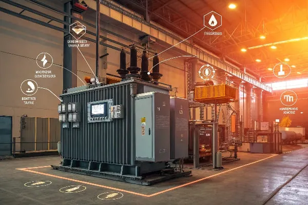
In my years of working with transformers, I’ve learned that knowing when to shut down is as important as knowing how to operate. Let’s dive into the specifics of transformer operation and shutdown to keep your power systems safe and efficient.
Conditions Leading to Transformer Shutdown: When Is Enough Enough?
Have you ever faced that heart-stopping moment when you realize your transformer might be on the brink of failure? Knowing when to shut it down can save you from disaster.
Transformer shutdown is necessary under conditions such as severe overheating, internal faults, significant oil leaks, or extreme environmental events. These situations pose immediate risks to the transformer’s integrity and overall system safety.
Throughout my career, I’ve encountered various scenarios that necessitated immediate transformer shutdown. Here’s what you need to know:
Critical Shutdown Conditions
-
Overheating:
- Excessive temperature rise in windings or oil
- Can lead to insulation breakdown and potential fire
-
Electrical Faults:
- Internal short circuits or ground faults
- Risk of explosive failure if not addressed immediately
-
Oil-Related Issues:
- Significant oil leaks or low oil levels
- Compromises cooling and insulation integrity
Environmental Triggers
| Condition | Risk | Action |
|---|---|---|
| Flooding | Water ingress, electrical hazards | Immediate shutdown and isolation |
| Severe storms | Lightning strikes, physical damage | Preemptive shutdown if severe warning |
| Earthquakes | Structural damage, oil spills | Shutdown and thorough inspection |
Operational Anomalies
Based on my experience, these operational signs often indicate the need for shutdown:
-
Abnormal Noise:
- Sudden loud buzzing or humming
- May indicate severe internal issues
-
Excessive Vibration:
- Can signify loose windings or core problems
- Risk of mechanical failure if left unchecked
-
Rapid Pressure Rise:
- Indicated by sudden Buchholz relay trips
- Often a sign of internal arcing or gas generation
I once encountered a situation where a transformer was making an unusual humming noise. Despite pressure from management to keep it running, I insisted on a shutdown. Upon inspection, we found that several of the core laminations had come loose, risking a catastrophic failure. This experience reinforced my belief in always erring on the side of caution when it comes to transformer safety.
Remember, the decision to shut down a transformer should never be taken lightly, but hesitation in critical situations can lead to far worse consequences. It’s always better to have a temporary outage than to risk a long-term disaster.
Impact of Abnormal Operating Conditions on Transformer Performance: What’s Really at Stake?
Ever wondered why some transformers seem to age faster than others? The secret often lies in how they’re operated under abnormal conditions. Let’s uncover the hidden costs of pushing your transformer to its limits.
Abnormal operating conditions can significantly impact transformer performance, leading to reduced efficiency, accelerated aging, and increased risk of failure. Overloading, harmonics, and voltage fluctuations are key factors that can compromise transformer integrity and lifespan.
In my years of experience, I’ve seen how abnormal conditions can turn a reliable transformer into a ticking time bomb. Here’s what you need to know:
Key Abnormal Operating Conditions
-
Overloading:
- Exceeds designed capacity, causing excessive heating
- Accelerates insulation degradation
-
Harmonic Distortion:
- Non-linear loads introduce harmonics
- Increases losses and causes localized heating
-
Voltage Fluctuations:
- Overvoltage or undervoltage conditions
- Stresses insulation and affects core performance
Performance Impacts
| Condition | Short-Term Impact | Long-Term Consequence |
|---|---|---|
| Overloading | Increased temperature, higher losses | Reduced lifespan, potential failure |
| Harmonics | Increased eddy currents, hot spots | Insulation breakdown, increased maintenance |
| Voltage Fluctuations | Increased magnetizing current, core saturation | Accelerated aging, reduced efficiency |
Efficiency and Lifespan Considerations
Based on my observations, here’s how abnormal conditions affect transformer performance:
-
Efficiency Reduction:
- Overloading increases copper losses
- Harmonics increase core losses
- Overall efficiency can drop by 1-2% under sustained abnormal conditions
-
Accelerated Aging:
- Normal transformer life expectancy is 20-30 years
- Continuous operation under abnormal conditions can halve this lifespan
-
Increased Maintenance Needs:
- More frequent oil changes and treatments
- Higher risk of unexpected failures requiring emergency maintenance
I once worked with a manufacturing plant that consistently overloaded their transformer during peak production hours. Over just three years, we observed a 20% decrease in the transformer’s expected lifespan. By implementing load management strategies and installing harmonic filters, we were able to extend the transformer’s life and improve its overall performance.
Hidden Costs of Abnormal Operation
-
Energy Losses:
- Increased losses mean higher energy bills
- Can add up to significant costs over time
-
Reliability Issues:
- Higher risk of unexpected outages
- Can lead to production losses in industrial settings
-
Environmental Impact:
- Increased energy consumption leads to higher carbon footprint
- Risk of oil leaks or fires in case of severe failure
Remember, while transformers are designed to handle some level of abnormal operation, consistent exposure to these conditions will inevitably take its toll. Proper monitoring, timely intervention, and adherence to operating guidelines are key to maintaining transformer performance and longevity.
Monitoring and Detection of Critical Operating Conditions: How to Stay Ahead of the Curve?
Ever felt like you’re always one step behind your transformer’s problems? It’s time to turn the tables and get ahead of potential issues before they become critical.
Effective monitoring and detection of critical operating conditions in transformers involve a combination of real-time sensors, regular testing, and advanced diagnostic techniques. Key parameters to monitor include temperature, oil condition, electrical characteristics, and gas composition.
Throughout my career, I’ve seen how proper monitoring can be the difference between a minor adjustment and a major overhaul. Here’s how to stay vigilant:
Essential Monitoring Parameters
-
Temperature Monitoring:
- Winding temperature indicators
- Top oil temperature sensors
- Hotspot temperature calculation
-
Oil Condition Monitoring:
- Moisture content sensors
- Oil level indicators
- Partial discharge detection
-
Electrical Parameter Monitoring:
- Load current measurement
- Voltage regulation tracking
- Power factor monitoring
Advanced Detection Techniques
| Technique | What It Detects | Frequency |
|---|---|---|
| Dissolved Gas Analysis (DGA) | Internal faults, oil breakdown | Monthly or continuous |
| Frequency Response Analysis (FRA) | Winding deformation, core issues | Annually or after events |
| Partial Discharge Monitoring | Insulation weaknesses | Continuous or periodic |
Real-Time Monitoring Systems
Based on my experience, implementing a comprehensive real-time monitoring system can provide invaluable insights:
-
SCADA Integration:
- Allows for remote monitoring and control
- Enables trend analysis and predictive maintenance
-
Online DGA Monitors:
- Continuous monitoring of key fault gases
- Early detection of developing faults
-
Fiber Optic Sensors:
- Direct measurement of winding temperatures
- High accuracy and fast response times
I once worked on a project where we installed a comprehensive online monitoring system on a critical substation transformer. Within the first month, the system detected a slight increase in acetylene levels, indicating a developing arc inside the transformer. We were able to schedule a controlled outage and repair the issue before it led to a catastrophic failure. This early intervention saved the utility millions in potential damages and outage costs.
Interpretation and Action
-
Alarm Systems:
- Set up multi-level alarms for different severity levels
- Ensure clear protocols for each alarm type
-
Trend Analysis:
- Regularly review historical data
- Look for subtle changes that might indicate developing issues
-
Predictive Maintenance:
- Use AI and machine learning algorithms to predict potential failures
- Schedule maintenance based on actual condition rather than fixed intervals
Remember, effective monitoring is not just about collecting data – it’s about interpreting that data and taking timely action. By implementing a robust monitoring and detection system, you can catch potential issues early, extend your transformer’s life, and avoid costly unplanned outages.
Safety Protocols for Transformer Shutdown: How to Power Down Without the Meltdown?
Ever wondered what it takes to shut down a transformer safely? It’s not just about flipping a switch – it’s a carefully choreographed process that can mean the difference between a smooth power-down and a potential disaster.
Safety protocols for transformer shutdown involve a systematic approach to de-energizing, isolating, and securing the equipment. Key steps include load transfer, circuit breaker operation, grounding, and lockout/tagout procedures. Proper execution of these protocols is crucial for personnel safety and equipment protection.
In my years of working with transformers, I’ve learned that a well-executed shutdown is as important as proper operation. Here’s how to do it right:
Step-by-Step Shutdown Procedure
-
Pre-Shutdown Assessment:
- Evaluate the reason for shutdown
- Plan for load transfer or power interruption
-
Load Transfer:
- Gradually reduce load on the transformer
- Transfer critical loads to alternate sources if possible
-
De-energization:
- Open the main circuit breaker
- Confirm power cut-off on all sides
Isolation and Grounding
| Step | Action | Purpose |
|---|---|---|
| Open Disconnects | Isolate transformer from all sources | Ensure complete isolation |
| Apply Grounds | Connect portable ground cables | Protect against residual charge and accidental re-energization |
| Verify Isolation | Use voltage detectors | Confirm absence of voltage |
Lockout/Tagout Procedures
Based on my experience, strict adherence to lockout/tagout procedures is non-negotiable:
-
Lockout:
- Apply locks to all isolation points
- Each worker should apply their personal lock
-
Tagout:
- Attach clear, informative tags to locked devices
- Include reason for shutdown, date, and responsible person
-
Verification:
- Double-check all lockouts and tags
- Conduct a team briefing to ensure everyone understands the scope of work
I once witnessed a near-miss incident where a maintenance team started work on a transformer that wasn’t properly isolated. Thanks to a last-minute catch during our safety check, we avoided what could have been a fatal accident. This experience reinforced the critical importance of following shutdown protocols to the letter.
Additional Safety Measures
-
Ventilation:
- Ensure proper ventilation if entering confined spaces
- Test for hazardous gases before entry
-
Oil Handling:
- Prepare for potential oil leaks or spills
- Have absorbent materials and containment equipment ready
-
Communication:
- Notify all relevant parties of the shutdown
- Establish clear communication channels for the duration of the work
Remember, a safe shutdown is the foundation for all subsequent maintenance or repair work. By following these protocols diligently, you not only protect your personnel but also set the stage for efficient and effective transformer work.
Consequences of Delayed Shutdown in Adverse Conditions: What’s the Worst That Could Happen?
Have you ever been tempted to keep a transformer running just a little longer, despite warning signs? The consequences of such decisions can be dire. Let’s explore what’s really at stake when you delay shutting down a transformer in adverse conditions.
Delayed shutdown in adverse conditions can lead to catastrophic transformer failure, posing severe safety risks and causing extensive damage. Consequences may include explosive failure, fire, environmental contamination, and prolonged power outages. The financial and safety implications of delayed action can far outweigh the perceived benefits of continued operation.

Throughout my career, I’ve seen the aftermath of delayed shutdowns, and the results are often sobering. Here’s what you need to know:
Immediate Risks of Delayed Shutdown
-
Catastrophic Failure:
- Internal faults can escalate rapidly
- Risk of explosive failure increases with time
-
Fire Hazard:
- Overheating can lead to oil ignition
- Electrical arcing can cause fires
-
Environmental Impact:
- Oil spills can contaminate soil and water
- Smoke from fires can release toxic substances
Long-Term Consequences
| Consequence | Impact | Recovery Time |
|---|---|---|
| Equipment Damage | Total loss of transformer | Months for replacement |
| System Instability | Cascading failures in the grid | Hours to days |
| Reputational Damage | Loss of customer trust | Years to rebuild |
Case Studies from My Experience
I’ve encountered several situations that highlight the dangers of delayed shutdown:
-
The Overloaded Substation:
- Transformer showed signs of overheating
- Decision to continue operation during peak demand
- Result: Catastrophic failure, 3-day outage for thousands of customers
-
The Ignored Oil Leak:
- Small oil leak detected but deemed "minor"
- Continued operation led to major leak
- Result: Environmental cleanup costs exceeded $1 million
-
The Persistent Partial Discharge:
- Partial discharge detected but not immediately addressed
- Insulation breakdown accelerated rapidly
- Result: Explosive failure, narrowly avoiding injuries
Hidden Costs of Delayed Action
-
Increased Repair Costs:
- Minor issues can escalate into major repairs
- Complete replacement often necessary after severe failures
-
Extended Downtime:
- Catastrophic failures lead to longer outages
- Replacement transformers may have long lead times
-
Legal and Regulatory Consequences:
- Potential fines for environmental violations
- Liability issues if failures lead to injuries or property damage
Remember, the decision to delay a shutdown is often driven by short-term thinking – avoiding a brief outage or meeting immediate demand. However, the potential consequences of this decision can far outweigh any temporary benefits. In my experience, it’s always better to err on the side of caution when it comes to transformer operation in adverse conditions.
Best Practices for Restarting Transformers After Shutdown: How to Power Up Safely?
Ever felt the pressure to get a transformer back online quickly after a shutdown? While speed is important, safety and proper procedures are paramount. Let’s explore how to restart your transformer the right way.
Restarting transformers after shutdown requires a systematic approach to ensure safety and prevent equipment damage. Key steps include thorough inspections, proper re-energization procedures, and careful monitoring during startup. Following best practices is crucial for avoiding issues like inrush currents and potential failures.
In my years of experience, I’ve learned that a careful restart can prevent a host of problems down the line. Here’s how to do it right:
Pre-Restart Inspection Checklist
-
Visual Inspection:
- Check for any physical damage or leaks
- Ensure all temporary grounds are removed
-
Electrical Tests:
- Conduct insulation resistance tests
- Verify transformer turns ratio
-
Oil Tests:
- Check oil levels and top up if necessary
- Perform dielectric strength test if shutdown was prolonged
Step-by-Step Restart Procedure
| Step | Action | Purpose |
|---|---|---|
| 1. Remove Lockouts | Systematically remove all locks and tags | Prepare for re-energization |
| 2. Close Disconnects | Re-establish electrical connections | Ready the transformer for power |
| 3. Energize Slowly | Use reduced voltage if possible | Minimize inrush current |
| 4. Monitor Closely | Watch for abnormal sounds or readings | Detect any issues immediately |
Managing Inrush Current
Based on my experience, managing inrush current is crucial during restart:
-
Point-on-Wave Switching:
- Use controlled switching devices
- Energize at optimal point of voltage wave
-
Staged Energization:
- For large transformers, energize in stages
- Start with low voltage winding if possible
-
Monitoring Inrush:
- Use current transformers to monitor inrush
- Be prepared to trip if inrush exceeds expected levels
I once worked on restarting a critical substation transformer after an emergency shutdown. We used point-on-wave switching and carefully monitored the inrush current. This careful approach prevented potential issues and allowed for a smooth restart, avoiding any damage to the transformer or disruption to the grid.
Post-Restart Monitoring
-
Temperature Monitoring:
- Watch for abnormal temperature rises
- Ensure cooling systems are functioning properly
-
Load Management:
- Gradually increase load to full capacity
- Monitor for any unusual heating or vibration
-
Gas Monitoring:
- If equipped, check dissolved gas levels
- Look for any sudden increases in key gases
Documentation and Reporting
-
Restart Log:
- Record all steps taken during the restart process
- Note any unusual observations or readings
-
Performance Tracking:
- Monitor transformer performance closely for the first 24 hours
- Compare with pre-shutdown benchmarks
-
Lessons Learned:
- Conduct a post-restart review
- Identify any areas for improvement in the restart procedure
Remember, a successful restart is not just about getting the transformer back online – it’s about ensuring its continued reliable operation. Taking the time to follow these best practices can save you from potential headaches and costly failures down the line.
Conclusion
Proper transformer operation, timely shutdown, and careful restart procedures are crucial for maintaining safety, reliability, and longevity of power systems. By understanding critical conditions, following safety protocols, and implementing best practices, we can ensure optimal transformer performance and prevent costly failures.
Is your three-phase transformer not performing as it should? The culprit might be lurking in the form of unwanted moisture. This silent enemy can wreak havoc on your equipment.
Water inlet and moisture in three-phase transformers are often caused by environmental factors, poor sealing, and inadequate maintenance. These issues can lead to reduced efficiency, insulation breakdown, and even complete transformer failure if not addressed promptly.
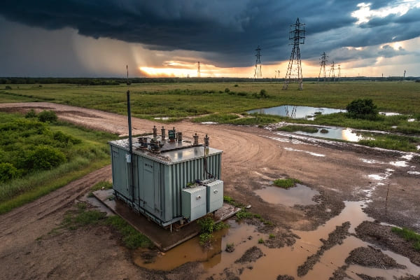
In my years of experience with transformer maintenance, I’ve seen how moisture can turn a reliable piece of equipment into a ticking time bomb. Let’s dive into the causes and solutions for this common yet critical issue.
Introduction to Three-Phase Transformer Water Inlet and Moisture Issues: Why Should You Care?
Have you ever wondered why some transformers seem to age faster than others? The answer often lies in how well they’re protected from their worst enemy: moisture.
Water inlet and moisture issues in three-phase transformers can significantly reduce their lifespan and efficiency. These problems can lead to insulation degradation, increased electrical losses, and potential safety hazards. Understanding these issues is crucial for effective transformer maintenance and operation.
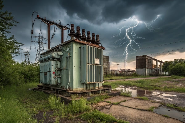
In my career, I’ve encountered numerous cases where moisture-related issues have caused unexpected downtime and costly repairs. Here’s why this topic deserves your attention:
The Hidden Danger of Moisture
-
Insulation Degradation:
- Moisture weakens the insulating properties of transformer oil and paper
- This can lead to electrical breakdowns and short circuits
-
Accelerated Aging:
- Moisture catalyzes chemical reactions that degrade insulation materials
- This can significantly shorten a transformer’s operational life
-
Reduced Efficiency:
- Wet insulation increases electrical losses
- This results in higher operating costs and reduced performance
Types of Moisture-Related Issues
| Issue | Description | Potential Consequences |
|---|---|---|
| Water Ingress | External water entering the transformer | Immediate risk of failure |
| Moisture Absorption | Gradual accumulation of moisture from the air | Long-term degradation |
| Condensation | Water droplets forming due to temperature changes | Localized insulation breakdown |
The Importance of Early Detection
Based on my experience, catching moisture issues early can save you from major headaches:
-
Regular Monitoring:
- Implement routine moisture level checks in transformer oil
- Use online monitoring systems for critical transformers
-
Visual Inspections:
- Look for signs of water ingress or condensation
- Check seals, gaskets, and breathers regularly
-
Performance Tracking:
- Monitor transformer efficiency and power factor
- Unexplained changes can be early indicators of moisture problems
I once worked on a project where a seemingly healthy transformer suddenly failed. Upon investigation, we found that years of undetected moisture accumulation had severely degraded its insulation. This incident led to a plant-wide review of moisture management practices, highlighting the importance of proactive measures.
Remember, when it comes to transformer moisture issues, prevention is always better than cure. Understanding the causes and impacts of moisture can help you implement effective strategies to protect your valuable assets.
Common Causes of Water Ingress in Three-Phase Transformers: Where’s the Leak?
Have you ever noticed water where it shouldn’t be in your transformer? You’re not alone. Water ingress is a common problem, but identifying the source can be tricky.
Water ingress in three-phase transformers often occurs due to poor sealing, damaged gaskets, cracked bushings, or inadequate protection from environmental elements. These issues can allow water to enter the transformer, leading to serious operational problems and potential failures.
Throughout my career, I’ve encountered various causes of water ingress in transformers. Let’s explore the most common culprits:
Key Entry Points for Water
-
Gasket Failures:
- Aging or improperly installed gaskets can allow water to seep in
- Common locations include manhole covers and bushing mountings
-
Cracked Bushings:
- Thermal cycling and physical stress can cause bushing cracks
- Even hairline cracks can allow moisture to enter over time
-
Radiator Leaks:
- Corrosion or physical damage to radiators can create entry points
- Often overlooked during routine inspections
Environmental Factors Contributing to Water Ingress
| Factor | Impact | Prevention Measures |
|---|---|---|
| Heavy Rain | Direct water exposure | Proper housing or weatherproof enclosures |
| Flooding | Submersion of lower components | Elevated installation or flood barriers |
| High Humidity | Moisture absorption through breathers | Use of dehumidifying breathers |
Maintenance-Related Causes
In my experience, some water ingress issues stem from maintenance practices:
-
Improper Oil Handling:
- Using wet or contaminated oil during maintenance
- Failing to properly seal the transformer after oil changes
-
Neglected Seals:
- Not replacing worn-out seals during routine maintenance
- Using incorrect seal materials for the application
-
Breather Maintenance:
- Failing to replace saturated silica gel in breathers
- Improper installation of breather systems
I once investigated a transformer that was experiencing frequent trips. We initially suspected an electrical issue, but a thorough inspection revealed a tiny crack in one of the bushings. This small defect had allowed a significant amount of water to enter the transformer over time. It was a stark reminder of how even minor imperfections can lead to major problems if left unchecked.
Remember, preventing water ingress is a continuous effort. Regular inspections, proper maintenance procedures, and prompt addressing of any signs of water entry are crucial for keeping your transformers dry and operational.
Environmental Factors Contributing to Moisture Accumulation: Is Your Transformer’s Environment Working Against You?
Have you ever wondered why some transformers seem to attract moisture like a magnet? The answer often lies in their surrounding environment. Let’s explore how the world around your transformer can become its worst enemy.
Environmental factors significantly contribute to moisture accumulation in three-phase transformers. High humidity, temperature fluctuations, and exposure to rain or flooding can all lead to increased moisture levels. Understanding these factors is crucial for implementing effective moisture control strategies.
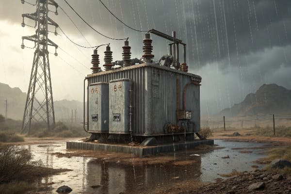
Throughout my career, I’ve seen how environmental conditions can make or break a transformer’s moisture resistance. Here’s what you need to know:
Key Environmental Factors
-
Humidity:
- High ambient humidity leads to moisture absorption
- Especially problematic in coastal or tropical areas
-
Temperature Fluctuations:
- Causes "breathing" in transformers, drawing in moist air
- Can lead to condensation inside the transformer
-
Precipitation:
- Direct exposure to rain or snow
- Can find its way into the transformer through small openings
Impact of Different Climates
| Climate Type | Moisture Challenges | Mitigation Strategies |
|---|---|---|
| Tropical | High humidity, heavy rainfall | Dehumidifiers, robust sealing |
| Coastal | Salt-laden moist air | Corrosion-resistant materials, frequent inspections |
| Desert | Extreme temperature swings | Thermal insulation, breather maintenance |
Seasonal Variations
Based on my experience, seasonal changes can significantly affect moisture levels:
-
Rainy Seasons:
- Increased risk of water ingress
- Higher ambient humidity levels
-
Summer:
- High temperatures can cause oil expansion and "breathing"
- Increased air conditioning use can lead to condensation
-
Winter:
- Cold temperatures can cause contraction and draw in moist air
- Snow and ice can create unique ingress risks
I once worked on a project in a coastal area where transformers were failing at an alarming rate. We discovered that the salt-laden air was not only increasing moisture absorption but also accelerating corrosion of seals and gaskets. By implementing a comprehensive environmental protection plan, including specialized coatings and more frequent maintenance, we were able to significantly extend the transformers’ lifespans.
Location-Specific Considerations
-
Indoor vs. Outdoor Installations:
- Indoor transformers generally face less extreme conditions
- Outdoor units require more robust protection measures
-
Elevation:
- Higher altitudes can lead to different pressure dynamics
- May require specialized breather systems
-
Proximity to Water Bodies:
- Increased humidity and potential for flooding
- May need additional waterproofing measures
Remember, understanding your transformer’s environment is the first step in protecting it from moisture. Regular environmental assessments and adapting your maintenance strategy to local conditions can make a world of difference in keeping your transformer dry and efficient.
Impact of Moisture on Transformer Performance and Lifespan: What’s at Stake?
Have you ever wondered why moisture is considered such a menace in the world of transformers? The answer lies in its far-reaching and often devastating effects on both performance and longevity.
Moisture significantly impacts transformer performance and lifespan by degrading insulation, increasing electrical losses, and accelerating aging processes. It can lead to reduced efficiency, increased risk of failure, and substantial shortening of the transformer’s operational life.
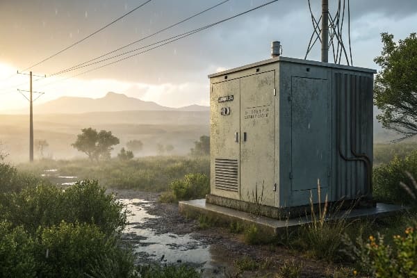
In my years of working with transformers, I’ve seen firsthand how moisture can turn a reliable piece of equipment into a liability. Let’s break down the key impacts:
Insulation Degradation
-
Paper Insulation:
- Moisture weakens cellulose fibers
- Accelerates the breakdown of paper insulation
-
Oil Insulation:
- Reduces dielectric strength of transformer oil
- Can lead to partial discharges and eventual failure
Electrical Performance Issues
| Issue | Cause | Consequence |
|---|---|---|
| Increased Losses | Higher conductivity of wet insulation | Reduced efficiency, higher operating costs |
| Partial Discharges | Moisture pockets in insulation | Gradual insulation breakdown, potential failure |
| Reduced Breakdown Voltage | Weakened dielectric strength | Increased risk of electrical faults |
Accelerated Aging Process
Based on my experience, moisture dramatically speeds up the aging of transformers:
-
Chemical Reactions:
- Moisture catalyzes hydrolysis of cellulose insulation
- Each doubling of moisture content can halve insulation life
-
Thermal Aging:
- Wet insulation has poorer heat dissipation
- Higher operating temperatures accelerate degradation
-
Oxidation:
- Moisture promotes oxidation of transformer oil
- Leads to sludge formation and reduced cooling efficiency
I once investigated a transformer that had failed prematurely, just five years into its expected 30-year lifespan. Analysis revealed that chronic moisture issues had accelerated its aging process to an extreme degree. This case underscored the critical importance of moisture control in preserving transformer life.
Long-Term Economic Impact
-
Increased Maintenance Costs:
- More frequent oil treatments and part replacements
- Higher labor costs for inspections and repairs
-
Energy Efficiency Losses:
- Wet transformers consume more power
- Can significantly increase operational costs over time
-
Premature Replacement:
- Moisture-damaged transformers may need early replacement
- Substantial capital expenditure and potential downtime
Remember, the impact of moisture on transformers is not just a technical issue – it’s an economic one. Protecting your transformers from moisture is an investment in their longevity and your bottom line. Regular monitoring, prompt addressing of moisture issues, and proactive maintenance are key to maximizing the life and performance of your transformers.
Detection and Diagnosis of Water Inlet in Three-Phase Transformers: How to Spot the Silent Killer?
Ever felt like you’re playing detective with your transformer? Detecting water inlet can indeed feel like solving a mystery. But fear not, I’ve got some tricks up my sleeve to help you crack the case.
Detection and diagnosis of water inlet in three-phase transformers involve various methods including oil analysis, electrical tests, and visual inspections. Key indicators include increased moisture content in oil, changes in dielectric strength, and visible signs of water ingress or corrosion.
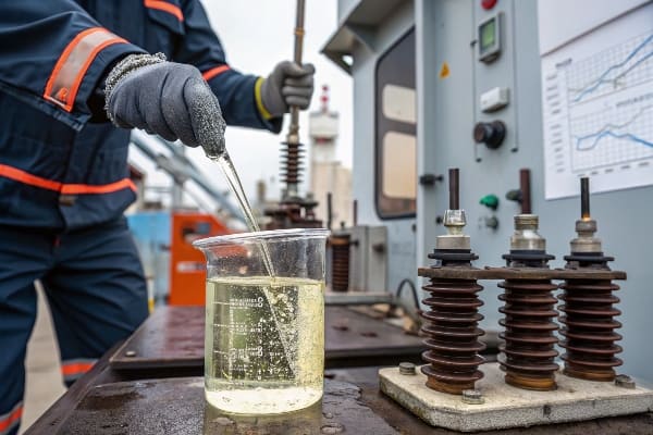
Throughout my career, I’ve developed a keen eye for spotting moisture issues. Here’s how you can become a moisture detective too:
Oil Analysis Techniques
-
Karl Fischer Titration:
- Measures water content in transformer oil
- Provides accurate quantitative results
-
Dielectric Strength Test:
- Indicates the oil’s ability to withstand electrical stress
- Decreased strength can signal moisture presence
-
Dissolved Gas Analysis (DGA):
- Can reveal moisture-related faults
- Helps distinguish between different types of issues
Electrical Testing Methods
| Test | What It Measures | Moisture Indication |
|---|---|---|
| Power Factor | Dielectric losses | Increased losses suggest moisture |
| Capacitance | Insulation condition | Changes can indicate moisture ingress |
| Frequency Response Analysis | Winding movement | Can reveal moisture-related deformation |
Visual Inspection Techniques
Based on my experience, never underestimate the power of a good visual inspection:
-
External Checks:
- Look for rust or corrosion on the tank
- Check for water droplets or stains around seals and gaskets
-
Internal Inspection:
- Examine the inside of the tank during maintenance
- Look for water droplets, rust, or sludge formation
-
Bushing Inspection:
- Check for cracks or discoloration
- Look for signs of water tracks or corrosion
I once encountered a transformer that had passed all routine electrical tests but was still underperforming. A thorough visual inspection revealed tiny water droplets forming inside the inspection window – a clear sign of a moisture problem that had been missed by standard tests. This experience taught me the value of combining multiple detection methods.
Advanced Detection Technologies
-
Online Moisture Monitoring:
- Continuous real-time monitoring of moisture levels
- Allows for early detection of developing issues
-
Acoustic Partial Discharge Detection:
- Can detect moisture-related partial discharges
- Useful for identifying localized moisture problems
-
Thermal Imaging:
- Can reveal moisture-related hotspots
- Useful for detecting issues in hard-to-reach areas
Remember, effective moisture detection is about more than just running tests – it’s about understanding your transformer and being alert to subtle changes. Regular, comprehensive checks using a combination of methods are your best defense against the silent killer that is moisture.
Preventive Measures and Maintenance Strategies for Moisture Control: How to Keep Your Transformer Dry and Happy?
Are you tired of constantly battling moisture in your transformers? It’s time to shift from reactive to proactive measures. Let’s explore how to keep your transformers as dry as a desert.
Effective moisture control in transformers involves a combination of preventive measures and regular maintenance. Key strategies include proper sealing, use of dehumidifying breathers, regular oil treatments, and environmental control. Implementing these measures can significantly extend transformer life and improve reliability.
In my years of transformer maintenance, I’ve learned that preventing moisture is far easier than dealing with its consequences. Here’s how to keep your transformers dry:
Sealing and Protection Strategies
-
High-Quality Gaskets and Seals:
- Use materials resistant to aging and environmental factors
- Regularly inspect and replace as needed
-
Weatherproofing:
- Apply weather-resistant coatings to external surfaces
- Ensure proper drainage around outdoor transformers
-
Breather Maintenance:
- Use dehumidifying breathers to prevent moisture ingress
- Regularly check and replace silica gel
Oil Maintenance Techniques
| Technique | Purpose | Frequency |
|---|---|---|
| Oil Filtration | Remove water and contaminants | Annually or as needed |
| Vacuum Oil Processing | Deep moisture removal | Every 3-5 years |
| Oil Regeneration | Restore oil properties | When oil quality degrades |
Environmental Control Measures
Based on my experience, controlling the transformer’s environment is crucial:
-
Temperature Regulation:
- Use cooling systems to prevent condensation
- Maintain consistent temperatures where possible
-
Humidity Control:
- Install dehumidifiers in transformer rooms
- Use dry air systems for critical applications
-
Flood Protection:
- Elevate transformers in flood-prone areas
- Install water detection and pumping systems
I once worked with a utility company that was struggling with moisture issues in their coastal substations. We implemented a comprehensive moisture control program, including advanced breather systems and regular oil treatments.The results were impressive – transformer failures due to moisture decreased by 80% over the next five years, saving millions in replacement costs and downtime.
Routine Maintenance Practices
-
Regular Inspections:
- Conduct visual checks for signs of water ingress
- Use infrared cameras to detect moisture-related hotspots
-
Periodic Testing:
- Perform regular oil tests to monitor moisture levels
- Conduct electrical tests to check for insulation degradation
-
Preventive Replacements:
- Replace aging gaskets and seals before they fail
- Upgrade to moisture-resistant components when possible
Advanced Moisture Control Technologies
-
Online Moisture Monitoring:
- Install real-time moisture sensors
- Set up alerts for when moisture levels exceed thresholds
-
Nitrogen Blanketing:
- Use dry nitrogen to create a moisture-free environment above the oil
- Particularly effective for transformers in high-humidity areas
-
Vacuum Oil Filling:
- Fill transformers under vacuum to minimize moisture content
- Especially important for new installations or after major maintenance
Remember, effective moisture control is an ongoing process, not a one-time fix. By implementing a comprehensive strategy that combines prevention, regular maintenance, and advanced technologies, you can significantly extend the life of your transformers and improve their reliability.
Conclusion
Moisture in three-phase transformers is a serious issue that can significantly impact performance and lifespan. By understanding the causes, implementing effective detection methods, and maintaining robust preventive measures, we can ensure optimal transformer operation and longevity.
