Are you having trouble picking the proper oil-immersed transformer for your power distribution needs? These important parts can be very complicated. Don’t worry! This detailed guide will clear up any confusion you may have about oil-immersed transformers, giving you the knowledge you need to make smart choices and improve the operation of your power system.
The Basics: The Main Parts and How Oil-Immersed Transformers Work
Do you just know what oil-immersed transformers are from books? A lot of specialists don’t pay attention to the small things that make these products work so well. Let’s take a closer look at the main parts and how they work. This will provide you more information that will help you comprehend and make better decisions.
The “Blood” That Can’t Be Missed: How Transformer Oil Keeps Things Cool and Insulated
Oil-immersed transformers rely on transformer oil 1to keep them cold and insulated. This fluid made from mineral oil has great dielectric strength, thermal conductivity, and chemical stability. Here’s why it’s important:
- Insulation: The oil fills up the spaces between the windings, which keeps the electricity from breaking down.
- Cooling: It moves heat from the core and windings to the outside of the transformer quickly and easily.
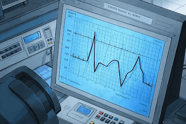
- Diagnostics: Analyzing oil on a regular basis can show problems that could become serious.
Key properties of transformer oil:
| Property | Typical Range | Importance |
|---|---|---|
| Dielectric Strength | 30-50 kV/mm | Prevents electrical breakdown |
| Viscosity | 8-12 cSt at 40°C | Affects cooling efficiency |
| Pour Point | -40°C to -60°C | Ensures fluidity in cold climates |
| Flash Point | >140°C | Safety indicator for fire risk |
A close look at the technology behind key components, from core to casing
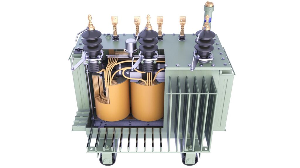
To understand how a transformer works as a whole, you need to know how the basic parts work together:
- Core: The core is usually made of grain-oriented silicon steel2, which lets magnetic flux flow through it easily.
- Windings: Primary and secondary coils, which are commonly made of copper or aluminum, move energy through electromagnetic induction.
- Bushings: These insulated openings let conductors safely leave the transformer tank.
- Tank: The sealed container holds all of the internal parts and the insulating oil.
- Cooling system: Radiators or fans help get rid of heat, which is important for keeping everything running smoothly.
Innovations in core materials, like amorphous metal cores3, can cut down on no-load losses by a lot, which makes the whole system more efficient.
Value is based on performance: Learning about the most important technical aspects of oil-immersed transformers
Are you feeling overwhelmed by all the technical details? You’re not the only one. A lot of buyers only look at the power rating and don’t think about other important factors that affect long-term performance and cost-effectiveness. Let’s look at the most significant things to think about.
Cooling Methods: The Key to a Transformer’s “Endurance”
For a transformer to last a long time and work well, it needs to be cooled properly. The way a transformer is cooled has a direct effect on how much load it can handle and how long it will last. Some common ways to cool things down are:
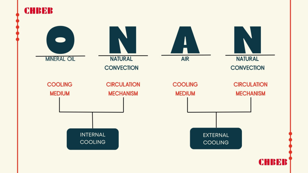
- ONAN (Oil Natural Air Natural): Uses natural oil flow and air cooling.
- ONAF (Oil Natural Air Forced): Uses fans to make the air cooler.
- OFAF (Oil Forced Air Forced): Uses fans and oil pumps to make cooling better.
- ODAF (Oil Directed Air Forced): Sends oil through windings to cool things down as much as possible.
Choosing the right way to cool down depends on things like:
- The temperature outside
- Profile of the load
- Setting up the environment
- Ability to do maintenance
Windings and Core: The Best Way to Balance Loss and Impedance
To get the most performance out of a transformer, it’s important to balance losses and impedance:
- No-load losses happen in the core because of hysteresis and eddy currents.
- Load losses happen because of resistance in the windings and stray losses.
- Impedance voltage: affects the current and voltage regulation in a short circuit.
Think about these trade-offs:
- Lower impedance makes voltage regulation better, but it also makes short-circuit current higher.
- Cutting down on losses usually means higher material costs and bigger transformers.
To make a smart choice, think about what you really need:
- Load profile (fixed vs. changing)
- Life expectancy
- Costs of energy
- Limited space
Operation, Maintenance, and Safety: Making Sure Transformers Work Well for a Long Time
Have you thought about how your choice of transformer would affect you in the long run? To get the best performance and longest life out of something, it needs to be used and cared for properly. Let’s look at some important ways to make sure your transformer runs well and safely for a long time.
Using oil analysis to check health: finding and fixing common problems
Regularly checking the oil in a transformer is the best way to tell how healthy it is. It can show:
- Moisture content: Too much moisture might damage insulation.
- Acidity: Shows that oil is breaking down and may be corroding.
- Dissolved gas analysis (DGA)4 finds problems inside the system, such as partial discharge or overheating.
Common signs of a problem:
- High hydrogen: Partial discharge
- High acetylene: Arcing
- More carbon monoxide: Paper insulation breaks down
Things you can do to stop it:
- Set up a consistent timetable for taking oil samples
- Use online systems to keep an eye on important transformers.
- When necessary, do oil filtering or regeneration on time.
Fire Protection and Environmental Safety: Keeping Oil-Immersed Transformers Safe
Never put safety off till later. Think about these important things:
- Protection from fire:
- Put up fire barriers and deluge systemss5
- In places where there is a lot of risk, use fluids that don’t catch fire as easily, like silicone or ester-based oils.
- Environmental protections:
- Set up the right systems to hold oil in place
- Use oils that break down in nature when you can
- Things to think about when it comes to earthquakes:
- Make sure the anchors are in the right place in areas that are likely to have earthquakes.
- Think about bushings and accessories that are rated for seismic activity.
Regular safety checks and drills can help find and fix possible problems before they become big ones.
Conclusion
Oil-immersed transformers are complex yet crucial components in power systems. You can make smart choices to improve performance, efficiency, and safety if you know their fundamental technology, important parameters, and maintenance needs. Keep in mind that the appropriate option today will make sure that power is distributed safely for years to come.
- Transformer oil. Wikipedia. Available at: ↩︎
- Grain-oriented electrical steels. ScienceDirect. Available at: ↩︎
- Amorphous metal transformer cores. IEEE Xplore. Available at: ↩︎
- Dissolved Gas Analysis (DGA) for Transformers. All About Circuits. Available at: ↩︎
- Fire protection solutions for transformers. Schneider Electric. Available at: ↩︎
Want to explore detailed specifications and models? You can download our product catalog or browse our website to learn more about CHBEB’s transformer solutions.
A Detailed Look at Oil-Immersed Transformers: From Basic Definition to Key Parts
Intro (PAS): Choosing the wrong transformer can lead to power outages, overheating, and expensive downtime. These hazards are worse when purchasers don’t understand the basics of oil. Find out how they function, which pieces are important, and how to keep them in good shape so you don’t make mistakes and have reliable performance over time.

What Is an Oil-Immersed Transformer? — Idea and How It Works
PAS lead: A lot of teams mix up oil-immersed with other designs, which leads to mis-specification. Not knowing “why oil?” makes decisions worse. Understanding the idea and the principle helps you choose safe, effective tools for tough jobs.
What does it mean and what makes it special? Why does it need “oil”?
An oil-immersed transformer moves energy between circuits using electromagnetic induction1. Its active elements are completely submerged in insulating oil. The oil does three important things:
- Insulation keeps the dielectric strength between high-voltage parts high, which stops flashover.
- Cooling: Takes heat from the windings and core and sends it to the radiators to be released.
- Protection: It keeps moisture and oxygen out, which slows down the aging and oxidation of insulation.
Oil-immersed units are prevalent in heavy industry, utility substations, and high-capacity power plants because they cool and insulate better.
How it works: Using electromagnetic induction in real life
According to Faraday’s Law, AC current in the main winding makes a magnetic flux in the laminated core, which makes voltage in the secondary winding. Oil immersion provides safe insulation and good heat removal, which keeps efficiency stable and extends service life.
- AC in primary → magnetic flux that changes direction in core
- Flux linkage → voltage in the secondary circuit
- Oil and paper system: stable under load in terms of thermal and dielectric properties
Breaking Down the Main Parts: Oil, Core, Windings, and Other Important Parts
PAS lead: Rating alone doesn’t usually cause underperformance; it’s usually parts that are left out. You can learn how to check, maintain, and specify things for long, reliable service by learning about oil, core, windings, and auxiliaries.
The “Core Medium” of Transformer Oil2
Transformer oil is more than just a coolant; it’s the living substance that keeps the system safe and stable:
- Electrical insulator: Stops electrified items from arcing within.
- Cooling medium: transfers heat to radiators or coolers so it can be released.
- Moisture barrier: Keeps dampness from getting into cellulose (paper) insulation.
- Condition indicator: Dissolved Gas Analysis3 (DGA) and dielectric tests show problems and wear and tear.
Depending on the voltage class, environmental policy, and fire safety needs, the selection ranges from mineral oils to synthetic/ester oils.
The “Heart” of the Transformer: Core and Windings
The laminated steel core reduces eddy currents and directs magnetic flux. The windings, which might be made of copper or aluminum, convey current and move energy through the core’s flux route.
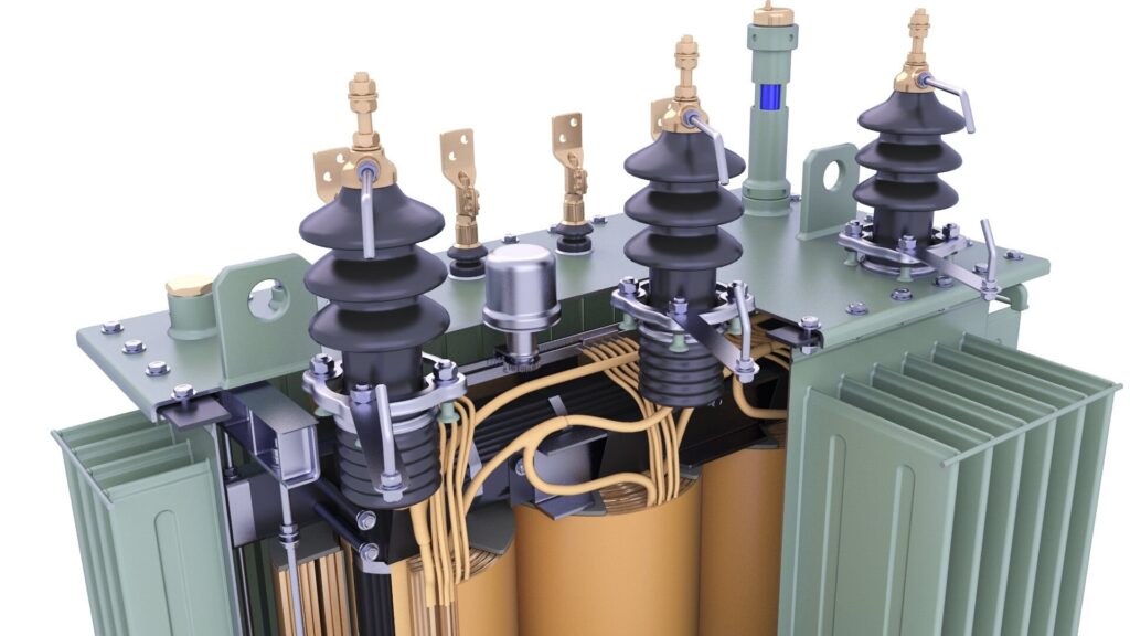
- Primary winding: Connected to the power source; creates magnetic flux.
- Secondary winding: Sends power to the load and gets induced voltage.
- Paper, varnish, spacers, and oil work together to keep the insulation system from breaking down.
Modern systems that use optimized core geometry, the right conductor, and oil immersion usually get efficiencies of above 98%.
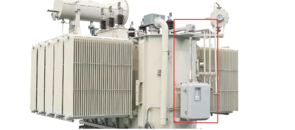
Oil tank, radiator, and other extra parts
- Main tank: An enclosure that can withstand pressure and holds the core, windings, and oil.
- Radiators and fins make the surface area bigger so that hot oil may lose heat more easily.
- The conservator tank keeps the oil from expanding or contracting when the temperature changes.
- Silica-gel breather: It keeps moisture from getting in by drying out the air that comes in.
- Buchholz relay4: Protects early by finding gas buildup from internal problems.
- Temperature gauges and indicators: Keep an eye on the levels and temperatures of the winding and oil.
How to Choose Between Oil-Immersed and Dry-Type Transformers and Important Maintenance Tips
PAS lead: Picking the wrong kind can lead to higher costs, safety issues, and failures that could have been avoided. To choose with confidence and use securely, compare features, match applications, and do the necessary maintenance.
Advantages and Disadvantages Compared: Cooling, Insulation, Cost, and Environmental Impact
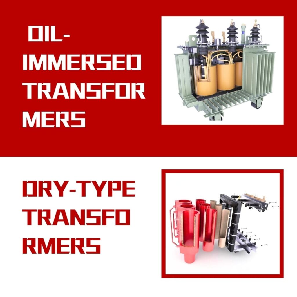
| Feature | Oil-Immersed Transformers | Dry-Type Transformers |
|---|---|---|
| Cooling | Excellent; oil circulation + radiators (ONAN/ONAF) | Moderate; air flow or resin encapsulation |
| Insulation | Oil + paper; high dielectric strength | Epoxy resin or air system |
| Initial Cost | Generally lower at high ratings | Often higher |
| Maintenance | Requires oil testing/monitoring | Lower routine maintenance |
| Fire Risk | Higher; oil is flammable | Lower; no oil |
| Environmental | Potential for oil leakage/pollution | Cleaner footprint, indoor-friendly |
For high-voltage, outdoor, or utility-scale uses, use oil-immersed. For indoor, public, or environmentally sensitive settings, use dry-type.
A Guide to Application Scenarios and Choosing
- Oil-Immersed: power plants, mining, steel, petrochemical, rural networks, and transmission/distribution substations.
- Dry-Type: Hospitals, schools, high-rises, shopping complexes, tunnels, and platforms in the ocean.
Checklist for selection:
- Match to the conditions of the place (indoor/outdoor, ambient, fire code).
- Weigh the risks of oil against the benefits of resin for safety and performance.
- Look at the total cost of ownership (TCO) instead of just the capital expenditures (CAPEX).
- Check that you are following the IEC/IEEE/ANSI standards5 for your area.
Maintenance and Questions That Are Often Asked (FAQ)
Things you need to do for maintenance:
- Set up regular oil testing for DGA, acidity, moisture, and dielectric strength.
- Check the silica-gel breather and change it when the color shows it is full.
- Keep an eye on the temperatures of the winding and oil, the loading patterns, and the cooling stage.
- Check the Buchholz relay and protection circuits, and look into any alerts right away.
- Look for leaks, rust, loose bushings, and gaskets that have worn out.
FAQ:
How long will a transformer that is submerged in oil last?
Usually 20 to 30 years, although it can last longer if you load it, cool it, and take care of the oil properly.
When is it time to change the oil in a transformer?
DGA shows problems when dielectric strength is below limits, acidity or moisture levels are too high, or both. This is after checking with trend data.
Which is safer: oil-immersed or dry-type?
Dry-type for inside or public places. Oil-immersed often works better and has more thermal headroom when the voltage is high or the job is tough outside.
What tests do you need to do on a regular basis?
Dielectric testing, DGA, moisture and acidity tests, thermography, protective relay functional checks, and tests of the turns ratio every so often.
Conclusion
In conclusion, PAS: Making bad choices can lead to downtime and safety issues. You may avoid problems by knowing how things work, what they are, and how to take care of them. Choose the proper type, keep the oil system in good shape, and your transformer will work well and safely for decades.
Learn More
Want to explore detailed specifications and models? You can download our product catalog or browse our website to learn more about CHBEB’s transformer solutions.
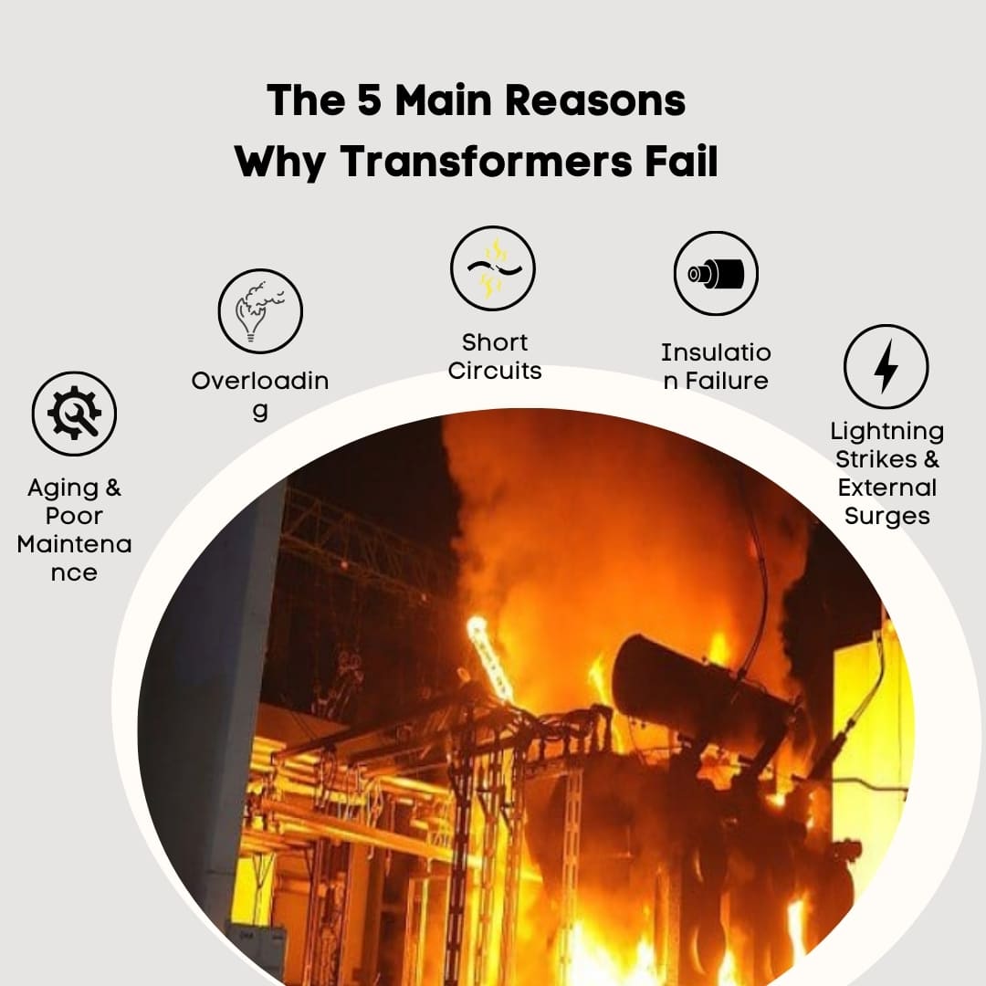
The 5 Main Reasons Why Transformers Fail
Problem: Failures don’t happen by chance. Agitate: When they hit, you have to deal with outages, safety issues, and expensive replacements. Solution: Deal with these five primary problems early on so that “surprise” incidents become regular maintenance tasks.
Overloading: The Quiet Killer
Constant loading above the nameplate rating causes winding hot spots, speeds up the aging of paper, and weakens the dielectric strength. Seasonal peaks, unapproved tie-ins, or growth that is too low might cause a “healthy” unit to go into thermal runaway.
- Make it safer: Plan for capacity growth or install a parallel unit when the trend peak/average load is reached.
- Stay calm: Keep an eye on the temperatures and deaths in hot spots, and turn on the designed fan and pump stages (for example, ONAN → ONAF).
- Plan ahead instead of praying: effective kVA selection and demand control are better than emergency replacements.
Short Circuits: The Quick Rise
Fault currents create enormous electrodynamic forces that change the shape of windings and hardware. Mechanical changes make clearances smaller, which can lead to repeated faults or flashover.
- Your playbook: Set up protection (relays, fuses, and breakers) so that problems clear quickly and only when they need to.
- Look at the skeleton: Torque audits and bracing checks make sure that the insides stay in place.
- After a fault, do a sanity check by running SFRA1 to find any winding movement before you power it back on.
Insulation Failure: The Breakdown Inside
Heat, moisture, and other pollutants break down oil/paper (or resin), which lowers the breakdown voltage. Micro-defects cause partial discharge, which leads to a flashover.
- Stay ahead: Regular testing for DGA2, BDV, moisture (ppm), acidity, and power factor (tan δ).
- Stay dry: Keep breathers, gaskets, and seals in good shape, and patch leaks right away.
- For dry types, keep an eye out for cracks in the resin and dust. You might want to think about doing partial discharge testing.
Lightning Strikes and Outside Surges
Bushings and windings are hit by atmospheric impulses and switching transients that have a steep front. Insulation gets holes in it if there aren’t the right pathways.
- To protect against it, put MOV surge arresters3 next to bushings and check that the grounding is strong.
- Keep it tidy: Check and clean the bushings to stop tracking and surface flashover.
- Use RC snubbers or pre-insertion resistors when you need to to tame switching spikes.
Age and bad upkeep
Oxidation of the oil, sludge, unsecured connections, rusted taps, and worn OLTC contacts all quietly create the stage for disaster. Aging isn’t bad; it’s not taking care of it that is.
- Do the plan: Set clear limits on both time-based and condition-based maintenance.
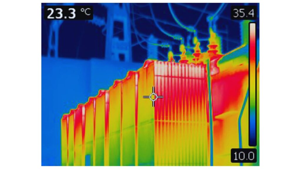
- Look at the heat: Thermography shows heated joints, and torque audits repair them.
- OLTC4 love: Check contacts, check resistance, and service on time.
Quick Reference: What Causes It, What to Look For, and How to Avoid It
| Cause | The Science | Early Symptoms | How You Stay Safe |
|---|---|---|---|
| Overloading | Thermal aging reduces dielectric strength | High top-oil, frequent fans, thermal alarms | Load studies, uprating/parallel units, cooling upgrades |
| Short Circuits | Electrodynamic forces deform windings | Nuisance trips, abnormal noise, SFRA drift | Protection coordination, bracing checks, post-fault tests |
| Insulation Failure | Moisture/heat/contamination lower BDV | Rising moisture, high tan δ, DGA fault gases | DGA, oil treatment, IR/PI, sealing & breathers |
| Lightning/Surges | Steep impulses puncture insulation | Bushing tracking, arrester operations logged | MOV arresters, earthing, surface cleaning |
| Poor Maintenance/Age | Oxidation, sludge, loose joints | IR hot spots, OLTC arcing, sludge in oil | CBM + TBM, oil care, torque audits, OLTC service |
Beyond the Boom: How to See the Signs and Stay Safe
Problem: Explosions seem to happen right away. Agitate: In real life, clues show up weeks before they should. The greatest way to keep things from happening again is to learn the warning signs and the correct first steps.
Important Signs That a Transformer Is Failing
- Changes in sound: a louder hum, crackling, or random “pops.”
- Heat anomalies: a lot of high top-oil and hot-spot alarms; IR scans showing hot spots that are targeted.
- Electrical signs: tan δ is going up, IR/PI is going down, and SFRA traces are not typical.
- DGA alerts: spikes in hydrogen, acetylene, or ethylene patterns that show arcing or thermal problems.
- Oil/visual signs: Lower BDV, black oil, rising moisture ppm, bushing tracking, and leaks.
- Protection activity: More trips or arrester counter increases.
What Happens After an Explosion? A Quick Guide
- To isolate power, turn it off, lock it up, and make sure the location is safe.
- Set up an exclusion zone: Treat oil fires like Class B fires and execute the emergency plan for the site.
- Tell people and contain the spill: Call the utility or OEM and set up spill kits and environmental barriers.
- Check the PRD, Buchholz5/sudden-pressure relays, bushings, and tank integrity to stop re-energization.
- Record and take samples: pictures, relay logs, arrester counts, and oil/DGA if it’s safe.
- Find the root cause by doing a mechanical check, an SFRA, winding resistance tests, and insulation testing.
If there is a fire or you think there is internal arcing, you should leave the building and allow trained responders put it out.
From Failure to Fix: Real-World Ways to Stop Problems
The problem is that replacing broken units takes a long time and costs a lot of money. Agitate: It’s worse to keep making the same mistake. The answer is to use modern monitoring and preventive maintenance to make things last longer and lower the danger.
The Strength of Preventive Maintenance
Make a condition-based maintenance (CBM) strategy that includes regular testing and specific actions and thresholds. This way, decisions are based on evidence, not gut feelings.
- Routine tests: DGA + furan, moisture (ppm), BDV, acidity; IR/PI and tan δ (winding/bushings).
- SFRA and winding resistance are two things that affect mechanical health. Use published torque settings to tighten hardware.
- Check fans and pumps, clean radiators, replace desiccant, and rectify leaks as soon as you find them.
- OLTC maintenance: verify the contacts, verify the contact resistance, and service them according to the OEM’s schedule.
- Trend it: Use dashboards to look at temperatures, DGA gases, test results, and arrester numbers. Don’t just look at snapshots.
How technology is making transformers safer
- DGA (H2, C2H2), moisture-in-oil, bushing leakage current, hot-spot RTDs, and OLTC motor current are all monitored online all the time.
- IIoT alarms: Tickets are triggered by real-time thresholds, and the event context is saved for speedier response.
- Analytics and AI: Pattern recognition can tell you when insulation is getting old, where hotspots are, and when problems are about to happen.
- Better surge protection: High-energy MOV arresters and clean, low-impedance earth pathways help protect against impulse damage.
- Digital twins: Use thermal profiles and load optimization to reduce loss of life.

Do you need a plan for stopping something? We can map tests, intervals, and thresholds to your fleet and then match surge protection and capacity planning to your risk profile.
Conclusion
Transformers don’t usually “blow” without notice. Overloading, malfunctions, insulation breakdown, surges, and not keeping things up to date leave an obvious trail. To protect people and uptime and lower the entire lifetime cost, pay attention to the signals, act on the data, and engage in proactive monitoring.
FAQ
Q1: What is the most common reason a transformer blows?
Overloading and insulation deterioration are leading causes. Heat accelerates paper aging, lowering dielectric strength until a fault occurs.
Q2: Can a transformer fail without warning?
Rarely. Early signs—abnormal noise, hot spots, rising DGA gases, or repeated protection trips—usually appear weeks or months ahead.
Q3: How often should I test transformer oil?
For critical units, perform quarterly DGA and annual comprehensive oil tests (BDV, moisture, acidity). Adjust frequency based on trends.
Q4: Do surge arresters prevent lightning damage completely?
They greatly reduce risk but require correct rating, placement near bushings, solid earthing, and periodic health checks.
Q5: Is replacement always necessary after an explosion?
Not always. After safe isolation and inspection, repairs may be feasible. A full root cause analysis (SFRA, DGA, mechanical checks) guides the decision.
- Sweep Frequency Response Analysis (SFRA) — ↩︎
- Dissolved Gas Analysis (DGA) — ↩︎
- Lightning arrester (MOV surge arresters) — ↩︎
- Tap changer (On-load tap changer, OLTC) — ↩︎
- Buchholz relay — ↩︎
Want to explore more transformer insights or choose the right model for your project? Visit our homepage for full product details, or download our product catalog to see technical specifications and solutions tailored for you.
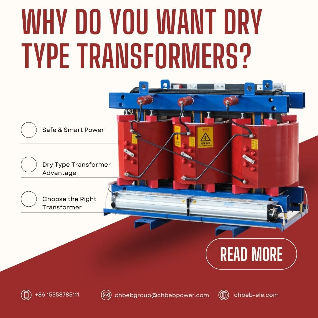
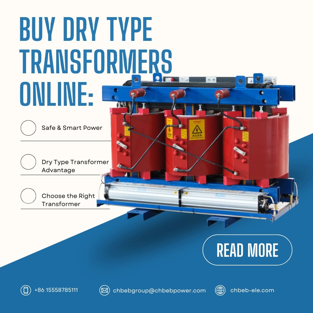
Why Do You Want Dry Type Transformers? The best answer for low-voltage uses
A lot of buyers have trouble picking the right type of transformer, which could lead to bad performance or greater prices. Dry type transformers1 overcome these problems by providing safe, efficient, and low-maintenance power solutions that are great for low-voltage uses.
A Comparison of the Main Benefits of Dry Type and Oil-Filled Transformers2
For a long time, oil-filled transformers have been the best way to distribute power, but they need oil management, leak prevention, and regular maintenance. On the other hand, dry type transformers use air or resin insulation, which gets rid of the dangers that come with oil.
- Safety: no oil that can catch fire, hence there are less fire concerns.
- Low Maintenance: No need to change or sample oil
- Good for the environment: little chance of oil leaks or soil pollution
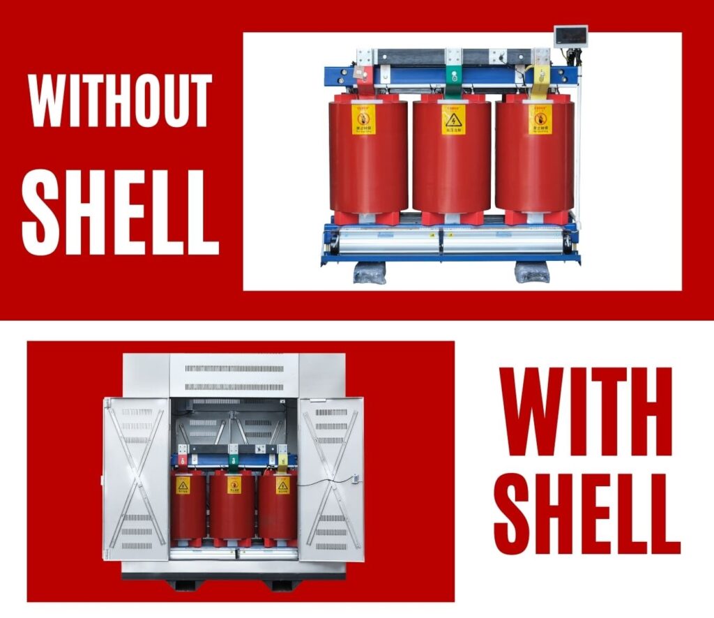
- Compact Installation: Can be put indoors without any particular protection
- Durability: Can handle dust and dampness in tough conditions
This makes them perfect for places like shopping malls, schools, factories, and renewable energy projects where safety and following the rules are very important.
How to Choose the Right Transformer for Your Needs When Shopping Online
If you pick the wrong transformer, it could not work as well, get too hot, or break down too soon. Choosing the appropriate one makes sure it is secure, reliable, and will last a long time, especially when you buy it online and can’t see it in person.
Learn about important specs including kVA, voltage, phase, and winding materials.
For each project, the specifications of the transformer must be exactly right for the load and the environment.
| Specification | Description | Buyer Tip |
|---|---|---|
| kVA Rating3 | Power capacity of the transformer | Choose a kVA that matches or slightly exceeds your maximum load. |
| Primary & Secondary Voltage | Input and output voltages | Ensure compatibility with your local grid and equipment. |
| Phase | Single-phase or three-phase design | Use single-phase for residential/light commercial, three-phase for industrial loads. |
| Winding Material | Copper or aluminum conductors | Copper offers higher efficiency, aluminum is lighter and more cost-effective. |
An expert provider can do load calculations to make sure that what you buy fits your demands.
Customization Services: Making Solutions That Fit Your Specific Projects
Transformers that you may buy off the shelf might not work for specific uses. Customization makes ensuring that your transformer fulfills certain installation, performance, or regulatory needs.
- Unusual voltage combinations for export projects
- Better cooling solutions for hot weather
- Special boxes for putting things inside or outside
- Designs for reducing harmonic interference in sensitive electronics4
If you work with a supplier that offers engineering help, you can receive exactly what your project needs without having to make expensive sacrifices.
The Buying Process and Long-Term Value: From Asking Questions to Getting Help After the Sale
You shouldn’t have to give up assistance just because you buy online. The top vendors will help you from the first question to after-sales service, making sure you get the most value out of the transformer’s life.
- First, tell us about your load requirements, site circumstances, and compliance criteria.
- Technical Proposal: The supplier gives you specs, drawings, and a price quote.
- Order Confirmation: agreeing on the price, delivery time, and payment terms.
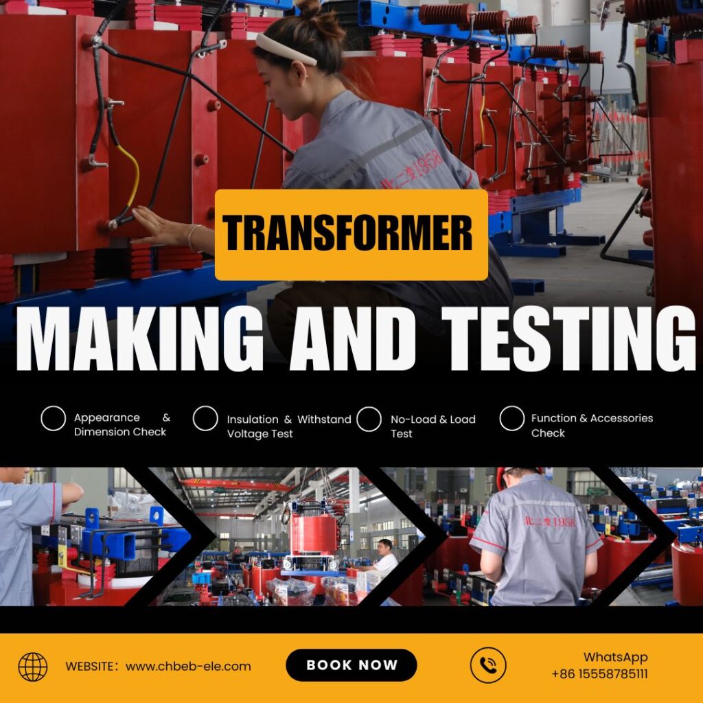
- Making and Testing: The transformer is made and tested to meet standards like IEC, IEEE5, and others.
- Delivery and Installation Help: Logistics are set up with the option of getting help on-site or from a distance.
- Service after the sale includes warranty coverage, spare parts, and technical help.
Frequently Asked Questions (FAQ): A Quick Guide to Common Problems
Q1: Is it okay to use a dry type transformer outside?
Yes, but only if it has a waterproof casing that can handle outdoor circumstances.
Q2: How long does a dry type transformer last?
With the right care, they usually last 20 to 30 years.
Q3: Do dry type transformers cost more than oil-filled ones?
The initial expenditures are a little higher, but the lower maintenance and safety compliance costs usually make up for it.
Q4: How quickly can I acquire a bespoke transformer?
The time it takes to get leads varies, but it’s usually between 2 and 6 weeks, depending on how complicated the project is and when it can be made.
Conclusion
For low-voltage and specialized projects, dry type transformers are a safe, easy-to-maintain, and environmentally responsible choice. You may buy online with confidence and make sure it will work for a long time if you know what you want and work with a trustworthy source.
Ready to Find the Perfect Dry Type Transformer?
Explore our full range of Dry Type Transformers to match your project requirements, or download our Product Catalog for detailed specifications and technical data.
Introduction
Choosing the improper type of dry transformer1 can cause expensive downtime, safety risks, and early failure. A lot of purchasers feel confused by technical specifications and advice that doesn’t agree. This tutorial breaks it down so you can choose the transformer that is safest, most efficient, and least expensive for your needs.
What Dry Type Transformers Are and Why They Are Important
Issue: A lot of people think “dry type” means it’s just a safer transformer, but they don’t know how it works or what it’s good at.
Agitate: If you don’t know this, you might spend too much money or pick a model that doesn’t work well in your area.
Let’s start by explaining what dry type transformers are and why they are becoming more popular around the world.
What does it mean to have a dry type transformer?
A dry type transformer doesn’t utilize mineral oil or other liquids to cool down. Instead, it uses air or solid insulation. Resin or varnish protects its windings and core, and it cools down with natural or forced air. This makes it perfect for places that are indoors or care about the environment.
The Main Benefits of Dry Type and Oil-Filled Transformers
| Feature | Dry Type Transformer | Oil-Filled Transformer |
|---|---|---|
| Cooling Medium | Air/Solid Insulation | Mineral/Synthetic Oil |
| Fire Safety | Higher (no flammable liquid) | Lower (oil is combustible) |
| Maintenance | Lower | Higher (oil testing, leak checks) |
| Environmental Impact | Minimal risk of spills | Risk of oil contamination |
| Cost | Higher initial cost | Lower initial cost |
| Applications | Indoor, sensitive sites | Outdoor, high-load grids |
The Most Important Types of Dry Type Transformers and Where They Work Best
Problem: Choosing the wrong type can cause it to not work as well or fail too soon.
Agitate: Not all dry type transformers work the same way in every situation.
Solution: For the best performance and longest life, match the proper type to your use.
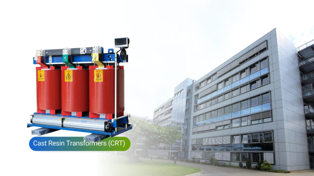
Cast Resin Transformers (CRT)
Core Features: Windings are completely covered in epoxy resin, which makes them very resistant to moisture, dust, and chemicals.
Pros: Very durable, needs little upkeep, and is safe for tough or corrosive conditions.
Drawbacks: more expensive and can’t be fixed if the resin splits or burns.
Common Uses: Hospitals, chemical industries, underground mines, and ships.
Vacuum Pressure Impregnated (VPI) Transformers
Main Features: Windings are coated with varnish under vacuum and pressure, and then baked to make them stronger.
Pros: It’s cheaper, it lets heat escape well, and it can be fixed if it breaks.
Limitations: Not as resistant to high humidity or contamination.
Common Uses: Schools, data centers, and commercial structures.
Specialized Dry Type Transformers
K-Factor Rated: Made for data centers or factories with non-linear loads.
Harmonic Mitigation Models: Help sensitive electronics work better by lowering voltage distortion.
High-Temperature Designs: Work in places where the standard ratings are higher.
Decoding Key Specifications and Selection Parameters
Problem: If you don’t know things like the kVA rating or insulation class, you can buy the wrong thing.
Agitate: This can make things less safe, more costly to fix, or less efficient.
Before you buy, be sure you know what each setting implies.
KVA Rating: Choosing the Right Size for Current and Future Loads
kVA tells you how much load the transformer can handle. To get kVA, use this formula: kVA = (Load Voltage × Load Current) ÷ 10002
Always leave room for future growth and environmental derating.
Voltage Class: Meeting the needs of both the primary and secondary systems
To avoid problems with performance, be sure that both the supply and load voltages are compatible.
Class of insulation and rise in temperature
For example, models with 150°C rise survive longer and run cooler than models with 220°C rise.
Longer life and better performance come from a lower temperature rise.
Losses and Efficiency
No-Load Losses: Energy lost while a transformer is turned on but not doing anything.
Load losses happen when energy is lost while under load.
To be in compliance and save money, follow the efficiency criteria set by DOE 2016, NEMA TP-1, or GB 20052-2020.3
IP Rating and Enclosure
IP544: shielded from dust and splashes, therefore it’s suitable for outdoor settings that are sheltered.
NEMA 3R: Weatherproof for outside use.
Pick based on the dangers in the area.
Winding Material: Copper vs. Aluminum
| Property | Copper | Aluminum |
|---|---|---|
| Conductivity | Higher | Lower |
| Cost | Higher | Lower |
| Weight | Heavier | Lighter |
| Mechanical Strength | Higher | Lower |
Impedance
Changes the short-circuit current and the voltage regulation. If it’s too low, there’s a chance of excessive fault currents. If it’s too high, the voltage will drop when it’s loaded.
Cost of maintenance, longevity, and lifetime
Problem: A lot of people think that “dry type” means “no maintenance.”
Agitate: Ignoring things shortens life and makes failure more likely.
Follow a simple maintenance plan and think on the lifetime cost instead of the purchase price.
Common Mistakes and Signs of Trouble
- Overheating
- Insulation cracks
- Unusual humming noise
- Discoloration of windings
The List of Important Maintenance Tasks
- Visual inspection every 6–12 months
- Cleaning dust and debris
- Tightening connections
- Infrared thermography5 for hot spots
- Insulation resistance tests
Analysis of Lifetime Cost (LCC)
Think about more than simply the purchase price. Think about installation, energy losses, maintenance, and disposal. Models with high efficiency frequently offer a better return on investment.
A process for choosing step by step
Problem: A lot of purchasers only care about price and don’t follow an organized process.
Agitate: This can cause safety problems or units that are too big or too little.
The answer is to use a planned approach..
A Flowchart for Systematic Transformer Selection
- Needs Assessment – Load profile, future expansion
- Environment Evaluation – Indoor/outdoor, humidity, dust
- Parameter Finalization – kVA, voltage, temperature rise, IP rating
- Vendor Comparison – Certifications, track record, support
Picking a Manufacturer You Can Trust
- International certifications (NEMA, IEC, GB/T)
- Proven track record in your industry
- Strong after-sales service
Conclusion
To choose the proper dry type transformer, you need to find a balance between performance, safety, and long-term expenses. Follow a plan, make sure the specs fit your space, and spend money on quality. Your electrical system will be more reliable if you do these things.
- Dry type transformer — Wikipedia ↩︎
- Transformer kVA calculation formula — Electrical Engineering Portal ↩︎
- DOE 2016 Energy Efficiency Standards — U.S. Department of Energy ↩︎
- IP Code — Wikipedia ↩︎
- Infrared thermography in electrical inspections — ScienceDirect ↩︎
Ready to Find the Perfect Dry Type Transformer?
Explore our full range of Dry Type Transformers to match your project requirements, or download our Product Catalog for detailed specifications and technical data.

Dry Type Transformers Explained: A Comprehensive Guide to Their Operation, Advantages, and Applications
What is a transformer that is dry? A Look at the Main Ideas and Benefits
If you pick the wrong type of transformer, it could overheat, catch fire, or cost you a lot of money in downtime. Many engineers and procurement managers have a hard time finding the right balance between performance, safety, and maintenance in power distribution. For modern applications, dry-type transformers are a clean, safe, and efficient choice.
The main idea behind how dry-type transformers work
Oil is used for insulation and cooling in traditional transformers. In dry-type transformers, nevertheless, air and solid insulation materials do the trick. This gets rid of the chance of oil leaks, making them perfect for indoor and delicate settings.
The basic idea behind these transformers is electromagnetic induction1. A primary coil gets electrical energy, which causes voltage to flow through a magnetic core to a secondary coil. They stay cool and safe in different ways: with air ventilation and resin insulation instead of oil.
The main difference between dry-type and oil-immersed transformers is
The difference in insulation is huge. Oil-immersed transformers cool and insulate windings by putting them in oil, although this can be dangerous for the environment and for fires. Dry-type transformers get rid of all of these risks: no oil, no flammability, and no poisonous leaks.
| Feature | Dry-Type Transformer | Oil-Immersed Transformer |
|---|---|---|
| Cooling Method | Air/Natural Ventilation or Fan | Oil Circulation |
| Insulation | Epoxy Resin / Varnish | Mineral or Synthetic Oil |
| Fire Risk | Very Low | Medium to High |
| Maintenance | Minimal | Requires Oil Sampling |
| Indoor Use | Excellent | Limited |
Why Are Dry-Type Transformers Safer?
Safety is a must in high-risk areas like hospitals, schools, and businesses. Because they are flame-resistant and self-extinguishing, dry-type transformers are great for use indoors and in crowded locations.
Also, the fact that there is no flammable oil and that fire-resistant epoxy or varnish is used gives you peace of mind, especially in countries like Europe and North America where there are a lot of rules. A lot of models meet the safety criteria set by IEC 60076-112 and IEEE C57.12.91.
A Detailed Look at the Different Types of Dry-Type Transformers, Their Pros and Cons
Not every dry-type transformer is made the same way. Knowing the distinctions can help you pick the best solution for your project demands and the environment. Let’s look at the different types, their benefits, and any possible drawbacks.
VPI and CRT are the two main types.
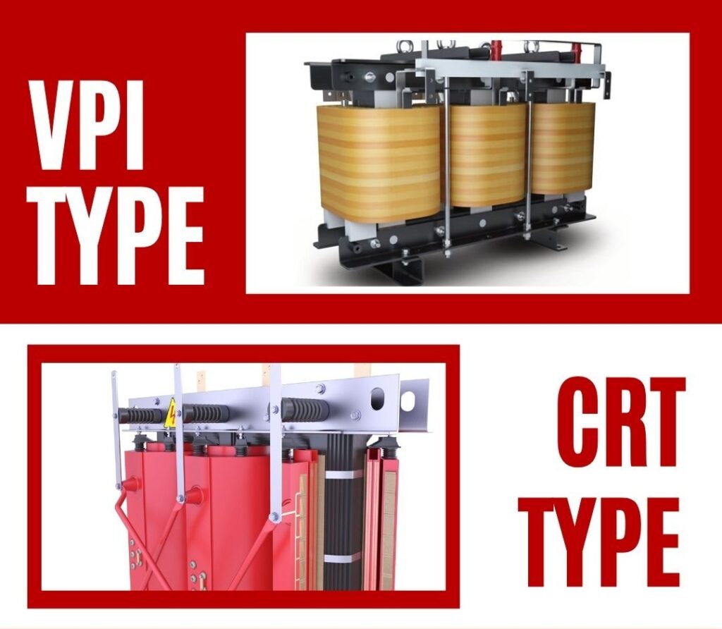
Dry-type transformers come primarily in two forms: VPI (Vacuum Pressure Impregnated)3 and CRT (Cast Resin Type).
- VPI Transformers: The windings are soaked in varnish while under pressure and vacuum. Air cools them down, and they are commonly employed in industrial and utility situations with lower humidity.
- CRT Transformers: Coils in CRT transformers are made of solid epoxy resin, which makes them more resistant to moisture and stronger mechanically. This makes them perfect for use in coastal or tropical areas.
| Specification | VPI Transformer | CRT (Cast Resin) Transformer |
|---|---|---|
| Insulation | Varnish-impregnated | Solid Epoxy Resin4 |
| Moisture Resistance | Moderate | High |
| Fire Resistance | Good | Excellent |
| Application | General Industrial | High Moisture / Indoor Use |
A Look at Core Benefits: Why They Are Commonly Used in Today’s Apps
- Safety: No chance of oil fires or poisonous leaks
- Good for the environment: no oil discharge, smaller environmental footprint
- Low Maintenance: You don’t have to change the oil or sample the fluid.
- Small size makes it easier to install indoors.
- No noise: Great for business spaces because it doesn’t make noise.
- Ready for Compliance: Meets global safety requirements
An Objective Look: Problems and Limitations of Dry-Type Transformers
- Higher Initial Cost: Cast resin models can cost more at first.
- Size and Weight: CRTs are bigger since they are covered in resin
- Efficiency: A little less energy efficient than oil-immersed when fully loaded
- For Use Outside Protection: When used outside, it must be kept in a protective container.
From Theory to Practice: Important Uses and Upkeep
It’s not only about how dry-type transformers work, but also where and how they do their job. Let’s go from technical details to real-world value and maintenance.
Common Use Cases and Examples
- Commercial Buildings: office towers and shopping complexes
- Hospitals and schools: safe, quiet, and clean inside
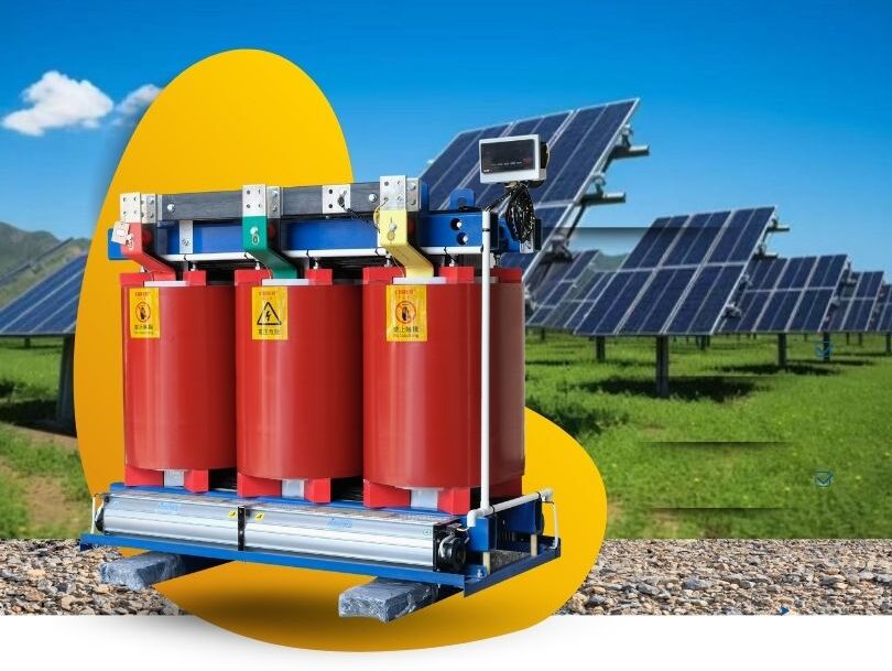
- Solar farms and wind substations are examples of renewable energy.
- Industrial Plants: This is especially true in places with a lot of humidity or chemicals.
- Transportation Hubs: Subways, airports, tunnels
For example, in 2024, a Dubai-based solar energy EPC put in 75 dry-type transformers in their PV project in the desert. The transformers didn’t need any maintenance for a whole year, even though they had to deal with high temperature changes and sand exposure. This was all because to cast resin insulation.
A Simple and Efficient Guide to Caring for and Maintaining Dry-Type Transformers
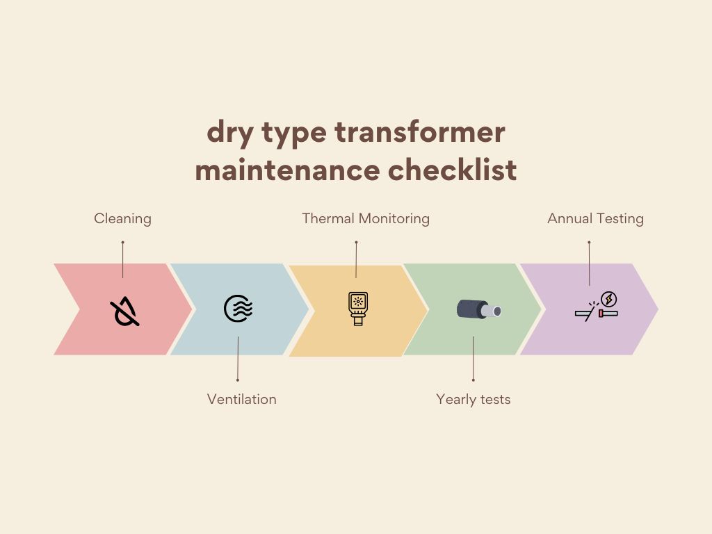
- Check for dust accumulation or signs of overheating once a month by looking at it.
- Cleaning: Don’t get anything wet; use a vacuum or dry cloth.
- Ventilation: Make sure that the cooling ducts are not obstructed.
- Thermal Monitoring: Use sensors that are already in place to keep an eye on temperature fluctuations.
- Yearly tests: IR thermography5 and insulation resistance checksperature changes
- Annual Testing: IR thermography and insulation resistance checks
A dry-type transformer can survive 20 to 30 years with the right maintenance, which is a great return on investment.
Conclusion
Dry-type transformers are safe, reliable, and work well all at the same time. They are a long-term, low-maintenance way to get clean power to people, whether you’re improving city infrastructure or creating renewable systems.
Are you struggling to choose the right dry type transformer for your project? With so many options available, it’s easy to feel overwhelmed. But making the wrong choice could lead to inefficiency, increased costs, or even safety risks.
Dry type transformers come in three main types: cast resin, VPI (Vacuum Pressure Impregnated), and epoxy encapsulated. Cast resin transformers offer excellent moisture resistance and are ideal for indoor use. VPI transformers are cost-effective and suitable for industrial applications. Epoxy encapsulated transformers excel in harsh environments. Each type has unique characteristics, advantages, and ideal use cases, which we’ll explore in detail to help you make an informed decision.
In this comprehensive guide, I’ll break down the key differences between cast resin, VPI, and epoxy encapsulated transformers. We’ll explore their structures, benefits, and ideal applications, helping you make the best choice for your specific needs. Whether you’re an engineer, project manager, or procurement specialist, this information will be invaluable in your decision-making process.
What Are Dry Type Transformers? Basic Definition and Benefits?
Have you ever wondered why some transformers don’t use oil for cooling? Or perhaps you’ve heard about dry type transformers but aren’t sure how they differ from traditional oil-filled units? Let’s dive into the world of dry type transformers and uncover their unique advantages.
Dry type transformers are electrical transformers that use air or solid insulation instead of oil for cooling and insulation. They offer enhanced safety, reduced fire risk, and minimal maintenance compared to oil-filled transformers. Dry type transformers are ideal for indoor installations, environmentally sensitive areas, and applications where oil leakage could be hazardous. They come in various types, including cast resin, VPI, and epoxy encapsulated, each suited for different environments and requirements.
Key Aspects of Dry Type Transformers
Let’s explore the fundamental characteristics and benefits of dry type transformers:
- Basic Structure and Components
- Cooling Methods
- Safety and Environmental Benefits
- Maintenance Requirements
- Common Applications
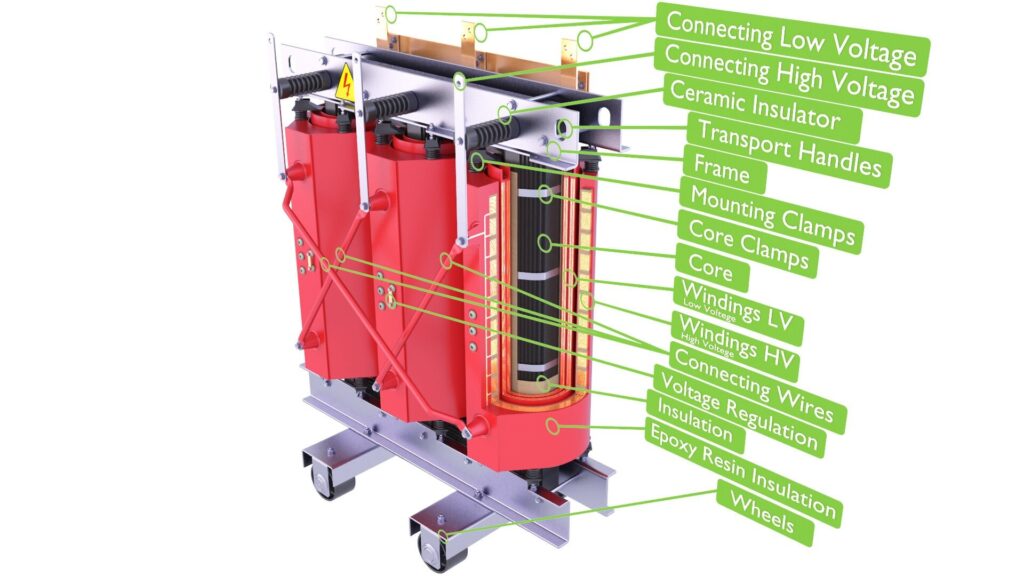
Basic Structure and Components
The anatomy of a dry type transformer:
- Core (typically made of silicon steel)
- Primary and secondary windings
- Insulation material (air, epoxy resin, or other solid materials)
- Enclosure or housing
I remember the first time I opened a dry type transformer during my early days as an engineer. The absence of oil and the clean, compact design immediately struck me. It was a stark contrast to the oil-filled units I was used to, and it sparked my interest in these innovative designs.
Cooling Methods
How dry type transformers manage heat:
- Natural air cooling (AN)
- Forced air cooling (AF)
- Combination of natural and forced air cooling (ANAF)
During a recent project for a high-rise building, we opted for a dry type transformer with forced air cooling. This choice allowed us to install the transformer in a smaller space while still meeting the building’s power requirements, showcasing the flexibility of dry type cooling methods.
Safety and Environmental Benefits
Advantages over oil-filled transformers:
- Reduced fire risk due to absence of flammable oil
- No risk of oil leaks or spills
- Environmentally friendly, especially in sensitive areas
Here’s a quick comparison of safety aspects:
| Aspect | Dry Type Transformer | Oil-Filled Transformer |
|---|---|---|
| Fire Risk | Low | Higher due to oil |
| Environmental Impact | Minimal | Potential oil spills |
| Indoor Use | Suitable | Often restricted |
| Maintenance | Low | Regular oil checks needed |
Maintenance Requirements
Ease of upkeep for dry type transformers:
- No oil to monitor or replace
- Periodic cleaning and inspection of windings
- Checking of connections and ventilation systems
Common Applications
Where dry type transformers excel:
- Indoor installations (office buildings, hospitals, schools)
- Industrial facilities with limited space
- Areas with strict environmental regulations
- Renewable energy projects (wind farms, solar installations)
Key points about dry type transformers:
- They use air or solid materials for insulation instead of oil
- Dry type transformers offer enhanced safety and reduced fire risk
- They are ideal for indoor and environmentally sensitive installations
- Maintenance requirements are generally lower than oil-filled units
- Various types exist, each suited for specific applications
In my experience, the versatility of dry type transformers has made them increasingly popular across various industries. I recall a project for a data center where the client was initially skeptical about using dry type transformers due to concerns about cooling efficiency. After implementing a forced air cooling system and demonstrating the safety benefits, the client was not only satisfied but also decided to standardize dry type transformers across their facilities.
For example, in a recent renewable energy project involving offshore wind turbines, we faced the challenge of installing transformers in a corrosive, space-constrained environment. By selecting epoxy encapsulated dry type transformers, we were able to ensure reliable operation in the harsh marine conditions while minimizing maintenance requirements – a crucial factor for offshore installations.
As we move on to discuss specific types of dry transformers, remember that each type has its unique strengths and ideal applications. Understanding these differences is key to selecting the right transformer for your specific needs.
Cast Resin Transformers: Structure, Use Cases, and Pros & Cons?
Have you ever wondered why some transformers look like they’re encased in solid blocks? Or perhaps you’ve heard about cast resin transformers but aren’t sure how they differ from other dry types? Let’s unravel the mystery of cast resin transformers and discover why they’re a popular choice in many applications.
Cast resin transformers are dry type transformers where the windings are encapsulated in epoxy resin. This design offers excellent protection against moisture, dust, and chemical contaminants. They’re ideal for indoor installations, especially in humid or polluted environments. Cast resin transformers provide high short-circuit strength, good overload capacity, and minimal maintenance requirements. They’re commonly used in commercial buildings, industrial facilities, and areas where fire safety is a primary concern.
Key Aspects of Cast Resin Transformers
Let’s dive deeper into the characteristics and applications of cast resin transformers:
- Structure and Manufacturing Process
- Cooling and Insulation Properties
- Advantages and Limitations
- Typical Applications
- Maintenance Considerations
Structure and Manufacturing Process
How cast resin transformers are made:
- Windings are wound with insulated conductors
- Coils are placed in molds and filled with epoxy resin under vacuum
- Resin is cured to form a solid, void-free insulation
I once visited a manufacturing facility specializing in cast resin transformers. Watching the vacuum casting process was fascinating – seeing how the liquid resin transformed into a solid, protective shell around the windings gave me a new appreciation for the engineering behind these transformers.
Cooling and Insulation Properties
Managing heat and ensuring proper insulation:
- Natural air cooling is most common (AN)
- Forced air cooling can be added for higher capacities (AF)
- Excellent thermal properties of epoxy resin aid in heat dissipation
During a recent project for a chemical plant, we chose cast resin transformers specifically for their superior insulation properties. The epoxy encapsulation provided excellent protection against the corrosive atmosphere, ensuring long-term reliability in a challenging environment.
Advantages and Limitations
Pros and cons of cast resin transformers:
| Advantages | Limitations |
|---|---|
| Excellent moisture resistance | Higher initial cost compared to VPI |
| High short-circuit strength | Heavier than other dry types |
| Fire-resistant (self-extinguishing) | Limited to indoor or protected installations |
| Low maintenance requirements | Potential for cracking under extreme thermal cycling |
| Environmentally friendly |
Typical Applications
Where cast resin transformers shine:
- Commercial buildings (offices, shopping centers)
- Hospitals and healthcare facilities
- Educational institutions
- Industrial plants with humid or polluted environments
- Underground or subway installations
Maintenance Considerations
Keeping cast resin transformers in top shape:
- Regular visual inspections for cracks or damage
- Cleaning of ventilation openings
- Checking of electrical connections
- Monitoring of ambient conditions (temperature, humidity)
Key points about cast resin transformers:
- Windings are fully encapsulated in epoxy resin
- They offer excellent protection against environmental factors
- Cast resin transformers have high short-circuit strength
- They’re ideal for indoor installations in challenging environments
- Maintenance requirements are minimal but regular inspections are crucial
In my experience, cast resin transformers have proven invaluable in projects where reliability and safety are paramount. I recall a hospital expansion project where we needed to install transformers close to sensitive medical equipment. The cast resin units were perfect – their low electromagnetic emissions and fire-resistant properties provided the necessary safety assurances, while their compact design fit well within the space constraints.
For example, in a recent project involving a data center in a coastal area, we faced the challenge of high humidity and salt-laden air. By implementing cast resin transformers, we were able to ensure reliable power distribution without the risk of moisture ingress or corrosion that could have plagued other transformer types. The client was particularly impressed by the low maintenance requirements, which translated to reduced operational costs over time.
As we move on to discuss VPI transformers, keep in mind that while cast resin transformers excel in many applications, each type of dry transformer has its unique strengths. Understanding these differences is key to selecting the right transformer for your specific needs.
VPI (Vacuum Pressure Impregnated) Transformers: How They Work and When to Use Them?
Have you ever wondered how some transformers achieve excellent insulation without the bulk of cast resin? Or perhaps you’re curious about a more cost-effective alternative to cast resin transformers? VPI transformers might be the answer you’re looking for. But what exactly are they, and when should you consider using them?
VPI (Vacuum Pressure Impregnated) transformers are dry type transformers where the windings are impregnated with varnish under vacuum and pressure. This process fills voids and creates a uniform insulation layer. VPI transformers offer good moisture resistance, excellent heat dissipation, and are generally more cost-effective than cast resin types. They’re ideal for industrial applications, indoor substations, and projects where budget constraints are a factor. VPI transformers provide a balance of performance and economy.
Key Aspects of VPI Transformers
Let’s explore the main features and applications of VPI transformers:
- Manufacturing Process
- Insulation and Cooling Characteristics
- Advantages and Limitations
- Typical Use Cases
- Maintenance Requirements
Manufacturing Process
How VPI transformers are made:
- Windings are wound with insulated conductors
- Coils are placed in a vacuum chamber
- Air is removed, and varnish is introduced under pressure
- Varnish is cured to create a solid insulation layer
I remember visiting a factory that produced both cast resin and VPI transformers. The VPI process was particularly intriguing – watching the varnish penetrate every nook and cranny of the windings under vacuum was like seeing the transformer come to life. This experience gave me a deep appreciation for the engineering precision involved in creating these efficient machines.
Insulation and Cooling Characteristics
Managing heat and ensuring proper insulation:
- Natural air cooling is common (AN)
- Forced air cooling can be added for higher capacities (AF)
- Varnish provides good heat dissipation and moisture resistance
During a recent industrial project, we opted for VPI transformers with forced air cooling. This choice allowed us to meet the high power demands of the facility while maintaining a compact footprint. The excellent heat dissipation properties of the VPI insulation system proved crucial in maintaining efficiency under heavy loads.
Advantages and Limitations
Pros and cons of VPI transformers:
| Advantages | Limitations |
|---|---|
| Cost-effective compared to cast resin | Less moisture resistant than cast resin |
| Good heat dissipation | May require more frequent maintenance |
| Lighter weight than cast resin | Not suitable for extremely harsh environments |
| Suitable for most indoor applications | Limited outdoor use without additional protection |
| Can be rewound if damaged |
Typical Use Cases
Where VPI transformers excel:
- Industrial facilities and factories
- Indoor substations
- Commercial buildings with controlled environments
- Renewable energy projects (wind and solar farms)
- Educational institutions
Maintenance Requirements
Keeping VPI transformers in top condition:
- Regular visual inspections for signs of varnish degradation
- Cleaning of ventilation systems
- Checking of electrical connections
- Monitoring of ambient conditions (temperature, humidity)
- Possible re-varnishing after long periods of use
Key points about VPI transformers:
- Windings are impregnated with varnish under vacuum and pressure
- They offer a good balance of performance and cost-effectiveness
- VPI transformers have excellent heat dissipation properties
- They’re ideal for most indoor industrial and commercial applications
- Maintenance is more involved than cast resin but less than oil-filled types
In my experience, VPI transformers have often been the go-to choice for projects where budget constraints are a significant factor, but performance can’t be compromised. I recall a large-scale factory upgrade where the client needed to replace multiple transformers across various production lines. By choosing VPI transformers, we were able to provide reliable power distribution at a cost that fit within the project’s budget constraints. The client was particularly pleased with the balance of performance and economy.
For example, in a recent solar farm project, we faced the challenge of installing multiple transformers in a relatively controlled environment, but with strict budget limitations. VPI transformers proved to be the perfect solution. Their good performance in moderate indoor conditions, combined with their cost-effectiveness, allowed us to optimize the power distribution system without exceeding the project’s financial constraints. The ability to easily maintain and potentially rewind these transformers also appealed to the client’s long-term operational planning.
As we move on to discuss epoxy encapsulated transformers, remember that while VPI transformers offer an excellent balance of performance and cost, each type of dry transformer has its specific strengths and ideal applications. Understanding these nuances is key to making the best choice for your particular needs.
Epoxy Encapsulated Transformers: Best for Harsh Environments?
Have you ever wondered what type of transformer could withstand the most challenging conditions? Or perhaps you’re facing a project where standard dry type transformers just won’t cut it? Epoxy encapsulated transformers might be the solution you’re looking for. But what makes them so special, and are they really the best choice for harsh environments?
Epoxy encapsulated transformers are dry type transformers where the entire core and coil assembly is fully encased in epoxy resin. This design provides superior protection against moisture, dust, and chemical contaminants, making them ideal for harsh environments. They offer excellent resistance to thermal shock, high mechanical strength, and can withstand extreme temperatures. Epoxy encapsulated transformers are commonly used in offshore installations, chemical plants, and other challenging industrial settings where reliability under severe conditions is crucial.
Key Aspects of Epoxy Encapsulated Transformers
Let’s delve into the main features and applications of epoxy encapsulated transformers:
- Design and Manufacturing Process
- Environmental Resistance Properties
- Advantages and Limitations
- Ideal Applications
- Maintenance and Longevity
Design and Manufacturing Process
How epoxy encapsulated transformers are created:
- Core and coil assembly is prepared
- Entire assembly is placed in a mold
- Epoxy resin is injected under vacuum
- Resin is cured to form a solid, void-free encapsulation
I once had the opportunity to witness the manufacturing process of an epoxy encapsulated transformer. The precision required to ensure complete and uniform encapsulation was impressive. Seeing the finished product – a solid, monolithic unit – gave me a new appreciation for the robustness of these transformers.
Environmental Resistance Properties
Withstanding harsh conditions:
- Excellent resistance to moisture and humidity
- High tolerance to chemical exposure
- Ability to withstand extreme temperatures
- Resistance to vibration and mechanical stress
During a recent offshore wind farm project, we specified epoxy encapsulated transformers for the turbine platforms. Their ability to withstand the corrosive sea air, constant vibrations, and temperature fluctuations proved crucial in ensuring reliable power transmission from the turbines to the grid.
Advantages and Limitations
Pros and cons of epoxy encapsulated transformers:
| Advantages | Limitations |
|---|---|
| Superior environmental protection | Higher cost compared to other dry types |
| Excellent mechanical strength | Heavier weight |
| Resistant to thermal shock | Limited ability to dissipate heat in very high ambient temperatures |
| Can be used in outdoor installations | Difficult to repair if damaged |
| Long lifespan in harsh conditions |
Ideal Applications
Where epoxy encapsulated transformers excel:
- Offshore oil and gas platforms
- Chemical and petrochemical plants
- Mining operations
- Coastal and marine environments
- Outdoor installations in extreme climates
- Areas with high pollution or dust levels
Maintenance and Longevity
Ensuring long-term performance:
- Minimal maintenance requirements due to full encapsulation
- Regular visual inspections for any external damage
- Monitoring of electrical parameters
- Cleaning of external surfaces to maintain heat dissipation
Key points about epoxy encapsulated transformers:
- Entire core and coil assembly is fully encased in epoxy resin
- They offer superior protection against harsh environmental factors
- Epoxy encapsulated transformers have excellent mechanical strength
- They’re ideal for extreme environments and outdoor installations
- Maintenance is minimal, but regular monitoring is still important
In my experience, epoxy encapsulated transformers have been lifesavers in some of the most challenging projects I’ve worked on. I recall a project for a chemical plant located in a tropical, coastal area. The combination of high humidity, salt air, and corrosive chemical vapors would have quickly degraded most other transformer types. The epoxy encapsulated units we installed have been running flawlessly for years, with minimal maintenance required.
For example, in a recent mining project in a remote, arid region, we faced the challenge of extreme temperature fluctuations and high dust levels. Epoxy encapsulated transformers were the clear choice. Their robust construction withstood the harsh conditions, and the sealed design prevented dust ingress. The client was particularly impressed by the transformers’ reliability, which significantly reduced downtime and maintenance costs compared to their previous installations.
As we move on to compare these different types of dry transformers, it’s important to remember that while epoxy encapsulated transformers excel in harsh environments, each type has its own strengths and ideal applications. The key is to match the transformer type to your specific environmental and operational requirements.
Comparison Table: Cast Resin vs VPI vs Epoxy Encapsulated
When it comes to choosing the right dry type transformer for your project, understanding the key differences between cast resin, VPI, and epoxy encapsulated transformers is crucial. But with so many factors to consider, how can you easily compare these types side by side? Let’s break it down in a comprehensive comparison table.
Cast resin, VPI, and epoxy encapsulated transformers each have unique characteristics that make them suitable for different applications. Cast resin offers excellent moisture resistance and is ideal for indoor use. VPI transformers are cost-effective and suitable for most industrial applications. Epoxy encapsulated transformers excel in harsh environments. The choice depends on factors like environmental conditions, maintenance requirements, and budget constraints. This comparison will help you identify the best option for your specific needs.
Detailed Comparison of Dry Type Transformers
Let’s dive into a comprehensive comparison of these three transformer types:
| Feature | Cast Resin | VPI | Epoxy Encapsulated |
|---|---|---|---|
| Structure | Windings encapsulated in epoxy | Windings impregnated with varnish | Entire assembly encased in epoxy |
| Moisture Resistance | Excellent | Good | Superior |
| Chemical Resistance | Very Good | Good | Excellent |
| Mechanical Strength | High | Moderate | Very High |
| Heat Dissipation | Good | Very Good | Good |
| Weight | Heavy | Lighter | Heaviest |
| Cost | High | Moderate | Highest |
| Maintenance | Low | Moderate | Very Low |
| Typical Applications | Indoor, moisture-sensitive areas | Industrial, cost-sensitive projects | Harsh, corrosive environments |
| Outdoor Suitability | Limited | Limited | Suitable with proper enclosure |
| Overload Capacity | Good | Good | Excellent |
| Noise Level | Low | Low to Moderate | Low |
| Repairability | Difficult | Possible | Very Difficult |
| Lifespan | Long | Moderate to Long | Very Long |
Key Insights from the Comparison
-
Environmental Protection:
Epoxy encapsulated transformers offer the highest level of protection against environmental factors, making them ideal for the harshest conditions. Cast resin follows closely, while VPI provides good protection for most indoor industrial applications. -
Cost Considerations:
VPI transformers are generally the most cost-effective option, making them attractive for large-scale industrial projects. Cast resin offers a balance of performance and cost, while epoxy encapsulated transformers come at a premium but offer unparalleled durability in extreme conditions. -
Maintenance Requirements:
Epoxy encapsulated transformers require the least maintenance, followed by cast resin. VPI transformers may need more frequent inspections and potential re-varnishing over time. -
Application Flexibility:
Cast resin transformers are versatile for various indoor applications. VPI transformers excel in industrial settings, while epoxy encapsulated units are the go-to choice for harsh environments and outdoor installations. -
Long-term Reliability:
All three types offer good reliability, but epoxy encapsulated transformers typically have the longest lifespan in challenging conditions. Cast resin follows closely, with VPI offering good longevity in appropriate environments.
In my experience, this comparison has been invaluable when consulting with clients on transformer selection. I remember a project where we were upgrading the electrical infrastructure of a large manufacturing complex. Different areas of the facility had varying environmental conditions and budget constraints. By referring to a comparison like this, we were able to strategically deploy a mix of VPI transformers in general industrial areas and cast resin units in more moisture-sensitive locations. This approach optimized both performance and cost-effectiveness across the entire project.
For example, in a recent multi-site renewable energy project, we used this type of comparison to tailor our transformer selections. We chose VPI transformers for the main indoor substations where cost was a significant factor, cast resin units for areas with moderate environmental challenges, and epoxy encapsulated transformers for offshore wind turbine platforms exposed to extreme marine conditions. This strategic mix ensured optimal performance and reliability across all sites while managing the overall project budget effectively.
As we move on to discuss how to choose the right dry type transformer for your application, keep this comparison in mind. It serves as a valuable reference point, but remember that each project has unique requirements that may influence your final decision.
How to Choose the Right Dry Type Transformer for Your Application?
Are you feeling overwhelmed by the options available in dry type transformers? With cast resin, VPI, and epoxy encapsulated transformers each offering unique benefits, how do you determine which one is best suited for your specific application? Let’s break down the decision-making process to help you make an informed choice.
Choosing the right dry type transformer involves considering several key factors: environmental conditions, load requirements, budget constraints, and maintenance capabilities. For indoor applications with moderate environmental challenges, cast resin transformers often provide an excellent balance. VPI transformers are ideal for cost-sensitive industrial projects with controlled environments. Epoxy encapsulated transformers are best for harsh outdoor or highly corrosive conditions. Always consider future expansion needs and long-term operational costs in your decision.
Key Considerations for Selecting the Right Transformer
Let’s explore the main factors to consider when choosing a dry type transformer:
- Environmental Conditions
- Load Requirements and Capacity
- Installation Location and Space Constraints
- Budget Considerations
- Maintenance Capabilities and Long-term Costs
Environmental Conditions
Assessing the operating environment:
- Indoor vs. outdoor installation
- Humidity and moisture levels
- Presence of corrosive chemicals or salt air
- Temperature extremes and fluctuations
- Dust and pollution levels
I once consulted on a project for a coastal industrial facility where the client initially considered VPI transformers to save on costs. After a thorough environmental assessment revealing high humidity and salt content in the air, we recommended cast resin transformers instead. This decision, while more expensive upfront, prevented premature failure and costly replacements down the line.
Load Requirements and Capacity
Matching transformer capacity to your needs:
- Current and future power requirements
- Peak load considerations
- Overload capacity needs
- Voltage regulation requirements
During a recent data center expansion project, we had to carefully consider both current needs and future growth. By selecting cast resin transformers with slightly higher capacity than immediately required, we provided room for the planned expansion without needing to replace the units in the near future.
Installation Location and Space Constraints
Considering physical limitations:
- Available floor space
- Height restrictions
- Ventilation and cooling requirements
- Accessibility for maintenance and replacement
Here’s a quick guide for space considerations:
| Transformer Type | Space Efficiency | Cooling Needs | Installation Flexibility |
|---|---|---|---|
| Cast Resin | Moderate | Good | Indoor, some outdoor with enclosure |
| VPI | Good | Very Good | Primarily indoor |
| Epoxy Encapsulated | Low | Moderate | Indoor and outdoor |
Budget Considerations
Balancing cost and performance:
- Initial purchase cost
- Installation expenses
- Long-term operational costs
- Expected lifespan and replacement costs
Maintenance Capabilities and Long-term Costs
Assessing ongoing care requirements:
- Frequency of required inspections
- Complexity of maintenance procedures
- Availability of skilled maintenance personnel
- Potential for repairs or rewinding
Key points for selecting the right transformer:
- Carefully assess your environmental conditions
- Consider both current and future load requirements
- Evaluate installation location and space constraints
- Balance initial costs with long-term operational expenses
- Assess your maintenance capabilities and resources
In my experience, the most successful transformer selections come from a holistic evaluation of all these factors. I recall a project for a pharmaceutical manufacturing facility where we initially leaned towards VPI transformers due to budget constraints. However, after a comprehensive analysis of the clean room environments, potential for chemical exposure, and the critical nature of the processes, we opted for cast resin transformers. This decision, while more expensive initially, provided the necessary reliability and reduced the risk of contamination, aligning perfectly with the facility’s stringent requirements.
For example, in a recent renewable energy project involving both solar and wind installations, we faced diverse environmental conditions across multiple sites. We implemented a mixed approach: VPI transformers for the main substation where conditions were controlled and cost was a factor, cast resin units for the solar inverter stations exposed to varying weather, and epoxy encapsulated transformers for the offshore wind turbines. This tailored selection ensured optimal performance and reliability across all aspects of the project while managing costs effectively.
As you make your decision, remember that choosing the right dry type transformer is not just about meeting immediate needs—it’s about ensuring long-term reliability, efficiency, and cost-effectiveness for your specific application.
Conclusion
Selecting the right dry type transformer—whether cast resin, VPI, or epoxy encapsulated—depends on a careful assessment of environmental conditions, load requirements, installation constraints, budget, and maintenance capabilities. Each type offers unique advantages for specific applications. By understanding these differences and considering your long-term needs, you can make an informed decision that ensures optimal performance, reliability, and cost-effectiveness for your electrical system.
Thank you for joining me in this exploration of dry type transformers. Stay curious, stay informed, and let’s keep pushing the boundaries of what’s possible in power distribution and electrical engineering.

When planning an electrical system—whether for a residential building, factory, or control panel—one question almost always comes up:
"Should we use a fuse or a circuit breaker for protection?"
This decision, though often underestimated, can have major implications for safety, cost, reliability, and future maintenance.
Fuses and circuit breakers are both overcurrent protection devices, but they operate differently. Fuses are single-use devices that melt when overloaded, while circuit breakers can be reset after tripping. Fuses generally respond faster and are more compact, making them ideal for sensitive electronics and space-constrained applications. Circuit breakers offer easier resetting and are better for circuits requiring frequent switching. The choice depends on factors like response time needs, maintenance preferences, and installation requirements.
In this article, I’ll break down the real differences between fuses and circuit breakers, helping you make the right choice for your application. We’ll explore their working principles, compare key features, and provide practical guidelines for selection. Whether you’re a procurement specialist, an electrical engineer, or a project manager, this guide will equip you with the knowledge to make informed decisions about electrical protection in your systems.
What Is a Fuse and How Does It Work?
Have you ever wondered what happens inside that small glass tube or plastic housing when an electrical fault occurs? Fuses are often the unsung heroes of electrical safety, but how exactly do they protect our circuits and equipment?
A fuse is a simple yet effective overcurrent protection device. It consists of a metal wire or strip that melts when too much current flows through it, breaking the circuit and stopping the flow of electricity. This sacrificial design ensures that the fuse fails safely before other components in the circuit can be damaged. Fuses are rated for specific voltages and currents, and they come in various types such as cartridge fuses, blade fuses, and surface mount fuses for different applications.
Key Aspects of Fuses
Let’s explore the main features and workings of fuses:
- Basic Structure and Components
- Operating Principle
- Types of Fuses
- Response Characteristics
- Advantages and Limitations
Basic Structure and Components
The anatomy of a fuse:
- Metal wire or strip (the fusible element)
- Enclosure (glass, ceramic, or plastic)
- Terminals for connection to the circuit
I remember dissecting my first fuse as a young engineer. The simplicity of its design—just a thin wire inside a glass tube—belied its critical role in electrical safety. This hands-on experience really drove home the elegance of the fuse’s design.
Operating Principle
How a fuse protects your circuit:
- Normal operation: Conducts electricity without issue
- Overcurrent condition: Wire heats up and melts
- Circuit interruption: Creates an open circuit, stopping current flow
During a recent industrial project, we had to explain the fuse operation to a client who was skeptical about their reliability. Demonstrating the melting process using a controlled test setup not only convinced them but also highlighted the importance of proper fuse selection for their specific application.
Types of Fuses
Common fuse varieties:
- Cartridge fuses (used in industrial applications)
- Blade fuses (common in automotive systems)
- Surface mount fuses (for electronic circuit boards)
Here’s a quick comparison of common fuse types:
| Fuse Type | Typical Application | Current Range | Advantages |
|---|---|---|---|
| Cartridge | Industrial equipment | 0.1A – 600A | High interrupting capacity |
| Blade | Automotive | 1A – 100A | Easy visual inspection |
| SMD | Electronics | mA – few A | Space-saving |
Response Characteristics
Understanding fuse behavior:
- Fast-acting fuses for sensitive electronics
- Time-delay fuses for motors and other inductive loads
- Current vs. time curves for precise protection coordination
Advantages and Limitations
Weighing the pros and cons:
- Advantages: Fast response, no maintenance, compact size
- Limitations: One-time use, requires replacement after operation
Key points about fuses:
- They provide simple, reliable overcurrent protection
- Fuses operate by melting when exposed to excessive current
- Different types suit various applications and current ranges
- Response characteristics can be tailored to specific needs
- While effective, fuses require replacement after operation
In my experience, the simplicity of fuses often leads to underestimating their importance. I recall a project where a client insisted on using oversized fuses to prevent "nuisance" blowing. We had to demonstrate how this practice defeated the fuse’s purpose and could lead to equipment damage. It was a crucial lesson in respecting these small but vital components.
For example, in a recent solar power installation, we carefully selected specialized DC fuses for the photovoltaic arrays. The unique characteristics of solar power systems, with their potential for sustained DC arcs, required fuses specifically designed for this application. This choice was critical in ensuring long-term safety and reliability of the installation.
As we move on to discuss circuit breakers, keep in mind that while fuses excel in certain applications due to their simplicity and speed, each protection device has its own strengths and ideal use cases.
What Is a Circuit Breaker and How Does It Work?
Have you ever flipped a switch to restore power after an electrical fault? That switch is likely a circuit breaker, but have you ever wondered what’s happening inside when it trips? Circuit breakers are more complex than fuses, but they offer unique advantages in many applications.
A circuit breaker is a reusable electrical protection device that automatically interrupts the flow of current when it detects an overload or short circuit. Unlike fuses, circuit breakers can be reset after they trip, making them ideal for applications requiring frequent intervention. They operate using either a thermal, magnetic, or combined mechanism to detect faults. Circuit breakers come in various sizes and types, from small residential units to large industrial models, and can include additional features like ground fault protection or remote operation capabilities.
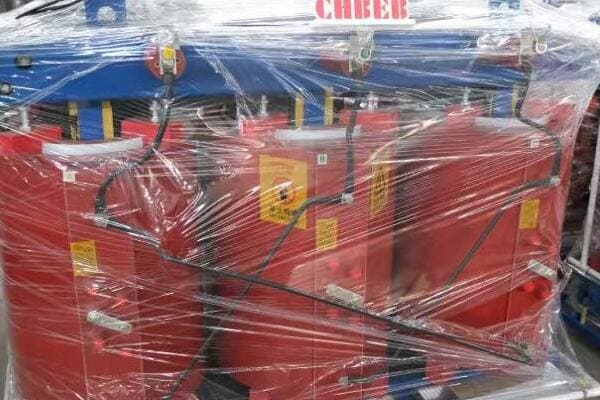
Key Aspects of Circuit Breakers
Let’s explore the main features and workings of circuit breakers:
- Basic Structure and Components
- Operating Mechanisms
- Types of Circuit Breakers
- Trip Characteristics
- Advantages and Limitations
Basic Structure and Components
The anatomy of a circuit breaker:
- Contacts (fixed and movable)
- Trip mechanism (thermal, magnetic, or both)
- Operating handle
- Arc extinguishing system
I recently had the opportunity to disassemble a circuit breaker during a training session. The intricate arrangement of springs, levers, and electromagnetic components gave me a new appreciation for these devices’ complexity and precision.
Operating Mechanisms
How circuit breakers protect your system:
- Thermal trip: Bimetallic strip bends with heat from overcurrent
- Magnetic trip: Electromagnet activates with high current spikes
- Combined thermal-magnetic: Provides protection against both overloads and short circuits
During a recent industrial automation project, we had to carefully select circuit breakers for motor protection. The challenge was finding devices that could handle the motor’s startup current without nuisance tripping, while still providing fast protection against short circuits. This experience underscored the importance of understanding different trip mechanisms.
Types of Circuit Breakers
Common circuit breaker varieties:
- Miniature Circuit Breakers (MCBs) for residential use
- Molded Case Circuit Breakers (MCCBs) for commercial and light industrial applications
- Air Circuit Breakers (ACBs) for high-current industrial systems
Here’s a quick comparison of common circuit breaker types:
| Type | Typical Application | Current Range | Key Features |
|---|---|---|---|
| MCB | Residential | 1A – 125A | Compact, easy to install |
| MCCB | Commercial/Industrial | 10A – 3000A | Adjustable trip settings |
| ACB | Heavy Industrial | 800A – 6300A | High interrupting capacity |
Trip Characteristics
Understanding breaker behavior:
- Instantaneous trip for short circuits
- Time-delayed trip for overloads
- Adjustable settings in some models for precise coordination
Advantages and Limitations
Weighing the pros and cons:
- Advantages: Reusable, visible ON/OFF status, can include additional protections
- Limitations: Generally slower response than fuses, more complex, higher initial cost
Key points about circuit breakers:
- They provide resettable overcurrent protection
- Circuit breakers use thermal and/or magnetic mechanisms to detect faults
- Different types suit various applications and current ranges
- Trip characteristics can often be adjusted for specific needs
- While more complex than fuses, they offer additional features and reusability
In my experience, the versatility of circuit breakers makes them indispensable in many modern electrical systems. I recall a project where we were upgrading an old factory’s electrical system. Replacing the outdated fuse boxes with modern circuit breakers not only improved safety but also significantly reduced downtime during fault conditions. The ability to quickly reset the breakers after addressing minor issues was a major advantage for the facility’s operations.
For example, in a recent data center project, we implemented a tiered protection scheme using different types of circuit breakers. We used ACBs for the main incoming supply, MCCBs for distribution boards, and MCBs for final circuits. This approach allowed for excellent selectivity, ensuring that faults were isolated at the lowest possible level, minimizing disruption to the data center’s critical operations.
As we move on to compare the key differences between fuses and circuit breakers, remember that while circuit breakers offer many advantages in terms of convenience and features, each protection device has its own strengths and ideal applications.
Key Differences Between Fuses and Circuit Breakers?
Are you struggling to decide between fuses and circuit breakers for your electrical project? The choice between these two protection devices can significantly impact your system’s safety, reliability, and maintenance requirements. But what exactly sets them apart, and how do these differences affect your decision?
Fuses and circuit breakers differ in several key aspects. Fuses generally respond faster to overcurrents but are one-time use devices. Circuit breakers are resettable and offer easier maintenance but typically have slower response times. Fuses are often more compact and cost-effective for simple applications, while circuit breakers provide better flexibility for systems requiring frequent intervention. The choice depends on factors like response time needs, maintenance preferences, space constraints, and specific application requirements. Understanding these differences is crucial for optimal system protection and operation.
Key Comparison Points
Let’s break down the main differences between fuses and circuit breakers:
- Operating Principle and Mechanism
- Response Time and Sensitivity
- Reusability and Maintenance
- Size and Installation Considerations
- Cost Factors
Operating Principle and Mechanism
How each device interrupts current:
- Fuses: Melt when overcurrent occurs, creating an open circuit
- Circuit Breakers: Use mechanical means (thermal or magnetic) to open contacts
I once demonstrated the difference in operation to a client using clear-cased fuses and circuit breakers. Seeing the fuse element melt versus the breaker contacts open really helped them understand the fundamental difference in how these devices work.
Response Time and Sensitivity
Comparing speed and accuracy of protection:
- Fuses: Generally faster response, especially for high fault currents
- Circuit Breakers: Slightly slower but offer more precise and adjustable trip characteristics
During a recent industrial project, we had to carefully consider response times for protecting sensitive equipment. In some cases, we opted for ultra-fast-acting fuses over circuit breakers to ensure the quickest possible interruption of fault currents.
Reusability and Maintenance
Long-term operational considerations:
- Fuses: One-time use, require replacement after operation
- Circuit Breakers: Can be reset multiple times, easier to maintain
Here’s a quick comparison of maintenance aspects:
| Aspect | Fuses | Circuit Breakers |
|---|---|---|
| Reusability | Single-use | Multiple operations |
| Post-fault Action | Replacement required | Manual or auto reset |
| Periodic Maintenance | Visual inspection | Functional testing needed |
| Lifespan | Indefinite if unused | May degrade over time |
Size and Installation Considerations
Physical and practical differences:
- Fuses: Generally more compact, simpler installation
- Circuit Breakers: Larger, may require more panel space, but offer easier accessibility
Cost Factors
Balancing initial and long-term expenses:
- Fuses: Lower upfront cost, but replacement costs add up
- Circuit Breakers: Higher initial investment, potentially lower long-term costs
Key points about the differences between fuses and circuit breakers:
- Fuses operate by melting, while circuit breakers use mechanical switching
- Fuses typically offer faster response times for high fault currents
- Circuit breakers are resettable and easier to maintain
- Fuses are often more compact, while circuit breakers offer better accessibility
- Cost considerations should include both initial and long-term expenses
In my experience, the choice between fuses and circuit breakers often involves balancing multiple factors. I recall a project where we initially specified circuit breakers throughout a large industrial facility for consistency. However, after a detailed analysis of certain critical circuits requiring ultra-fast protection, we ended up using a combination of circuit breakers for general distribution and specialized fuses for these sensitive areas. This hybrid approach provided the best overall protection scheme for the facility.
For example, in a recent renewable energy project, we had to protect both AC and DC circuits in a solar-plus-storage system. We used circuit breakers for the AC side, where occasional tripping was expected due to grid fluctuations, and specialized DC fuses for the battery and solar panel circuits. This combination leveraged the strengths of both protection types, ensuring optimal safety and performance of the system.
As we move on to discuss when to use fuses, remember that while these differences are significant, the best choice often depends on the specific requirements of your application. Understanding these distinctions is key to making an informed decision for your electrical protection needs.
When to Use a Fuse: Typical Applications and Advantages?
Are you wondering if a fuse is the right choice for your electrical protection needs? While circuit breakers are popular, fuses still play a crucial role in many applications. But when exactly should you opt for a fuse over a circuit breaker, and what advantages do they offer in specific scenarios?
Fuses are ideal for applications requiring fast response times, high interrupting capacities, and compact protection. They excel in protecting sensitive electronics, automotive systems, and high-fault-current industrial circuits. Fuses are preferred in scenarios where space is limited, cost is a primary concern, or where the speed of current interruption is critical. Common applications include semiconductor protection, battery systems, and certain types of motor circuits. Fuses offer advantages in simplicity, reliability, and the ability to handle high surge currents without nuisance tripping.
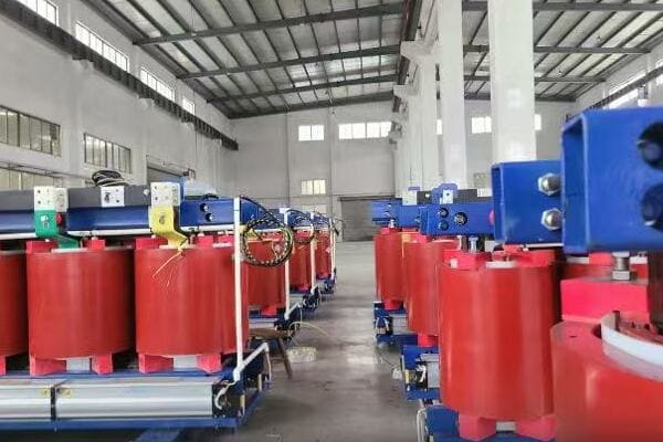
Key Scenarios for Using Fuses
Let’s explore the main applications and advantages of fuses:
- Protecting Sensitive Electronics
- Automotive Electrical Systems
- High Fault Current Industrial Applications
- Space-Constrained Installations
- Cost-Sensitive Projects
Protecting Sensitive Electronics
Safeguarding delicate components:
- Fast-acting fuses for quick response to overcurrents
- Surface mount fuses for PCB protection
- Precision fuses for test and measurement equipment
I recently worked on a project involving high-end audio equipment. We chose specialized audio fuses for critical signal paths. The ultra-fast response and low resistance of these fuses were crucial in maintaining the equipment’s high-fidelity performance while providing necessary protection.
Automotive Electrical Systems
Reliable protection in vehicles:
- Blade fuses for various automotive circuits
- High-current fuses for battery and alternator protection
- Fuse boxes for centralized, easy-to-manage protection
During a recent electric vehicle (EV) design consultation, we implemented a comprehensive fusing strategy. The combination of standard automotive fuses for auxiliary systems and specialized high-voltage fuses for the main power circuits ensured robust protection across the entire vehicle electrical system.
High Fault Current Industrial Applications
Managing extreme electrical conditions:
- High interrupting capacity fuses for transformer protection
- Semiconductor fuses for power electronics
- Current-limiting fuses to protect switchgear
Here’s a quick overview of fuse applications in different sectors:
| Sector | Application | Fuse Type | Key Advantage |
|---|---|---|---|
| Electronics | PCB protection | SMD fuse | Compact size |
| Automotive | Circuit protection | Blade fuse | Standardized, easy replacement |
| Industrial | Transformer protection | HRC fuse | High interrupting capacity |
| Renewable Energy | Solar panel strings | gPV fuse | DC arc interruption |
Space-Constrained Installations
Maximizingprotection in tight spaces:
- Miniature fuses for compact electronic devices
- Inline fuses for wiring harnesses
- Micro fuses for densely packed circuit boards
Cost-Sensitive Projects
Balancing protection and budget:
- Lower upfront costs compared to circuit breakers
- Simple replacement process reducing maintenance complexity
- Wide range of current ratings for precise protection sizing
Key points about when to use fuses:
- They excel in protecting sensitive electronic components
- Fuses are standard in automotive electrical systems
- High fault current industrial applications benefit from fuse protection
- Space-constrained installations often require fuse solutions
- Cost-sensitive projects can leverage the economic advantages of fuses
In my experience, the decision to use fuses often comes down to a combination of technical requirements and practical considerations. I recall a project for a large data center where we initially considered circuit breakers for all protection needs. However, after a detailed analysis of the power distribution units (PDUs), we opted for a hybrid approach. We used circuit breakers for the main feeds but implemented fuses within the PDUs themselves. This decision was driven by the need for extremely fast response times to protect sensitive server equipment, as well as space constraints within the PDU enclosures.
For example, in a recent renewable energy project involving a large solar farm, we faced the challenge of protecting long strings of photovoltaic panels. We chose specialized DC fuses designed for solar applications. These fuses not only provided the necessary protection against overcurrents but also had the capability to interrupt DC arcs, which are particularly dangerous in high-voltage DC systems. The compact size of these fuses also allowed for efficient design of the combiner boxes, maximizing the system’s overall efficiency.
As we move on to discuss when to use circuit breakers, remember that while fuses offer unique advantages in many scenarios, the choice between fuses and circuit breakers should always be based on a thorough analysis of your specific application requirements.
When to Use a Circuit Breaker: Ideal Scenarios and Use Cases?
Have you ever wondered why some electrical systems rely heavily on circuit breakers while others stick to fuses? Circuit breakers offer unique advantages in certain scenarios, but how do you know if they’re the right choice for your project? Let’s explore the situations where circuit breakers shine.
Circuit breakers are ideal for applications requiring frequent manual operation, easy reset after faults, or adjustable trip settings. They excel in residential and commercial electrical systems, industrial motor protection, and scenarios where remote operation or monitoring is needed. Circuit breakers are preferred when regular maintenance access is required, in systems with varying load profiles, or where coordination with other protective devices is crucial. Their ability to be reset without replacement makes them cost-effective for circuits prone to occasional overloads.
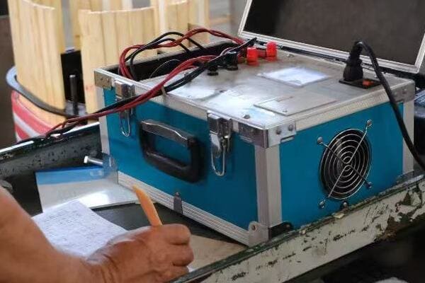
Key Scenarios for Using Circuit Breakers
Let’s explore the main applications and advantages of circuit breakers:
- Residential and Commercial Electrical Systems
- Industrial Motor Protection
- Systems Requiring Frequent Switching or Reset
- Applications Needing Adjustable Protection Settings
- Remote Operation and Monitoring Requirements
Residential and Commercial Electrical Systems
Providing accessible protection in buildings:
- Main service panels in homes and offices
- Branch circuit protection for lighting and appliances
- GFCI and AFCI breakers for enhanced safety
I recently oversaw the electrical renovation of an old apartment building. Replacing the outdated fuse boxes with modern circuit breaker panels not only improved safety but also significantly enhanced the residents’ ability to manage their electrical systems. The clear ON/OFF indicators and easy reset capability of circuit breakers were particularly appreciated by the tenants.
Industrial Motor Protection
Safeguarding critical machinery:
- Motor circuit protectors (MCPs) for short circuit protection
- Thermal-magnetic breakers for overload and short circuit protection
- Electronic trip units for precise protection and data logging
During a recent factory automation project, we implemented a comprehensive motor protection scheme using circuit breakers. The ability to adjust trip settings for different motor sizes and starting characteristics proved invaluable in optimizing the protection while minimizing nuisance tripping during normal operations.
Systems Requiring Frequent Switching or Reset
Managing dynamic electrical loads:
- Lighting control systems in commercial buildings
- Temporary power distribution in construction sites
- Laboratory equipment with varying power requirements
Here’s a quick overview of circuit breaker applications in different sectors:
| Sector | Application | Breaker Type | Key Advantage |
|---|---|---|---|
| Residential | Main panel | MCB | Easy reset, clear status indication |
| Commercial | Lighting control | MCCB with aux contacts | Remote operation capability |
| Industrial | Motor protection | MCP | Adjustable magnetic trip for inrush current |
| Data Center | Power distribution | Electronic trip MCCB | Data logging and remote monitoring |
Applications Needing Adjustable Protection Settings
Tailoring protection to specific needs:
- Variable frequency drive (VFD) protection in HVAC systems
- Generators with varying load profiles
- Critical process equipment requiring precise coordination
Remote Operation and Monitoring Requirements
Enhancing control and diagnostics:
- Smart circuit breakers in building management systems
- Remote-controlled breakers in utility substations
- Breakers with communication capabilities for industrial IoT applications
Key points about when to use circuit breakers:
- They are standard in residential and commercial electrical systems
- Circuit breakers excel in industrial motor protection applications
- They’re ideal for systems requiring frequent manual operation or reset
- Adjustable settings make them suitable for complex protection schemes
- Remote operation and monitoring capabilities enhance system management
In my experience, the versatility of circuit breakers often makes them the preferred choice in complex electrical systems. I recall a project involving a large manufacturing facility where we initially considered a mix of fuses and circuit breakers. After analyzing the facility’s operational needs, including frequent maintenance activities and the desire for remote monitoring, we decided to standardize on circuit breakers throughout the plant. This decision not only simplified maintenance procedures but also allowed for the implementation of a comprehensive power management system, improving overall energy efficiency and reducing downtime.
For example, in a recent smart building project, we leveraged the capabilities of advanced circuit breakers with built-in metering and communication features. These devices not only provided traditional overcurrent protection but also enabled real-time energy monitoring, load shedding, and integration with the building’s automation system. This level of functionality and control would have been impossible to achieve with traditional fuses.
As we move on to discuss how to choose the right device for your project, remember that while circuit breakers offer significant advantages in many scenarios, the best choice always depends on your specific application requirements, budget constraints, and long-term operational needs.
Choosing the Right Device for Your Project – Buyer’s Checklist?
Are you feeling overwhelmed by the decision between fuses and circuit breakers for your electrical project? With so many factors to consider, how can you ensure you’re making the right choice? Let’s break down the key considerations into a practical checklist to guide your decision-making process.
Choosing between fuses and circuit breakers involves evaluating several factors: system voltage and current, required interrupting capacity, response time needs, reset requirements, space constraints, and long-term maintenance considerations. For sensitive electronics or high fault current applications, fuses might be preferable. For systems requiring frequent resets or adjustable settings, circuit breakers are often better. Consider the initial cost versus long-term expenses, including potential downtime and replacement needs. Always consult relevant electrical codes and standards for your specific application.
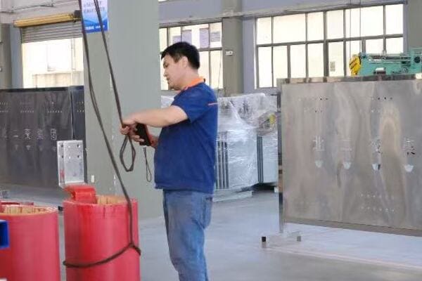
Key Considerations for Device Selection
Let’s explore the main factors to consider when choosing between fuses and circuit breakers:
- Electrical System Characteristics
- Protection Requirements
- Operational Considerations
- Physical and Environmental Factors
- Cost Analysis
Electrical System Characteristics
Matching the device to your system:
- Voltage rating: Must meet or exceed system voltage
- Current rating: Typically 125% of maximum continuous current
- Interrupting capacity: Must exceed maximum fault current
I recently consulted on a project where the initial protection devices were undersized for the available fault current. By carefully analyzing the system characteristics and potential fault scenarios, we were able to select properly rated devices, significantly enhancing the overall safety and reliability of the installation.
Protection Requirements
Ensuring adequate safeguards:
- Response time needs: Consider if ultra-fast protection is necessary
- Selectivity and coordination: How the device works with other protective elements
- Specific protection features: e.g., ground fault, arc fault detection
During a recent data center upgrade, we implemented a tiered protection scheme. This involved carefully selecting and coordinating circuit breakers with different trip characteristics to ensure that faults were isolated at the lowest possible level, minimizing disruption to critical systems.
Operational Considerations
Aligning with usage patterns and maintenance capabilities:
- Frequency of overcurrent events: Fuses for rare events, breakers for frequent occurrences
- Reset requirements: Consider if manual reset is feasible or if automatic reclosing is needed
- Monitoring and control needs: Circuit breakers offer more options for integration
Here’s a quick decision guide based on operational factors:
| Factor | Prefer Fuse | Prefer Circuit Breaker |
|---|---|---|
| Overcurrent Frequency | Rare | Frequent |
| Reset Needs | Replacement acceptable | Quick reset required |
| Remote Operation | Not needed | Desired |
| Adjustable Settings | Fixed protection sufficient | Flexibility needed |
Physical and Environmental Factors
Adapting to installation constraints:
- Available space: Fuses generally more compact
- Environmental conditions: Temperature, humidity, vibration tolerance
- Accessibility: Consider ease of replacement or reset
Cost Analysis
Balancing initial and long-term expenses:
- Initial purchase cost
- Installation expenses
- Potential downtime costs
- Long-term maintenance and replacement considerations
Key points for device selection:
- Match electrical ratings to your system characteristics
- Consider specific protection requirements and response time needs
- Evaluate operational factors like reset frequency and remote control needs
- Account for physical constraints and environmental conditions
- Analyze both initial and long-term costs
In my experience, the most successful protection schemes often involve a thoughtful combination of both fuses and circuit breakers. I recall a large industrial project where we initially planned to use circuit breakers exclusively for consistency. However, after a detailed analysis of each circuit’s specific needs, we ended up with a hybrid approach. We used circuit breakers for general distribution and motor circuits, but implemented specialized fuses for sensitive electronic equipment and high-fault-current areas. This tailored approach provided optimal protection while balancing cost and operational considerations.
For example, in a recent renewable energy project involving a solar farm with battery storage, we faced unique protection challenges. For the DC side of the solar arrays and battery systems, we chose specialized DC fuses designed for photovoltaic applications, offering fast response and high interrupting capacity. On the AC side and for general distribution, we implemented circuit breakers with advanced monitoring capabilities. This combination leveraged the strengths of both device types, ensuring comprehensive protection and facilitating efficient system management.
As we conclude our discussion, remember that choosing between fuses and circuit breakers is not always an either/or decision. Often, the best solution involves a strategic combination of both, tailored to the specific needs of each part of your electrical system.
FAQs: Fuse vs Circuit Breaker Selection
To address some common questions about choosing between fuses and circuit breakers:
-
Can I replace a fuse with a circuit breaker?
While it’s possible in some cases, it’s not always advisable or permissible. Replacing a fuse with a circuit breaker requires careful consideration of the circuit characteristics, available fault current, and relevant electrical codes. In many cases, especially in older systems or specialized applications, the existing fuse may be specifically designed for that circuit. Always consult with a qualified electrician or engineer before making such a change. -
Which one is safer for my home?
Both fuses and circuit breakers can provide safe protection when properly selected and installed. Circuit breakers are more common in modern homes due to their ease of use and reset capability. They also offer additional safety features like GFCI and AFCI protection. However, properly rated fuses can be equally safe and may be preferred in certain applications for their faster response times. -
Do circuit breakers respond as fast as fuses?
Generally, fuses respond faster than circuit breakers, especially for high fault currents. This is due to the simple melting action of the fuse element compared to the mechanical operation of a circuit breaker. However, the difference in response time is often negligible for most household and light commercial applications. In critical applications where ultra-fast response is crucial, specialized fuses are often preferred. -
Why are fuses still used if breakers exist?
Fuses offer several advantages that make them preferable in certain applications:- Faster response times, especially for high fault currents
- More compact size, useful in space-constrained applications
- Often lower cost, especially in high-voltage or specialized applications
- No moving parts, potentially higher reliability in harsh environments
- Better current-limiting abilities in some cases
Fuses remain crucial in automotive applications, sensitive electronics protection, and certain industrial and high-power scenarios.
Conclusion
Choosing between fuses and circuit breakers depends on specific application needs, including response time, reset requirements, space constraints, and long-term operational considerations. Both devices offer unique advantages: fuses excel in speed and simplicity, while circuit breakers offer convenience and adjustability. Often, the best protection scheme involves a strategic combination of both types, tailored to each part of the electrical system.
Thank you for joining me in this exploration of fuses and circuit breakers. Stay curious, stay informed, and let’s keep pushing the boundaries of what’s possible in power distribution and electrical engineering.

At first glance, a fuse might seem like a simple electrical component. But walk into any industrial warehouse or browse an electronics catalog, and you’ll quickly realize there are dozens of fuse types—each with different shapes, sizes, voltage ratings, and response times.
Fuses come in various types to meet diverse electrical protection needs. Common types include cartridge fuses for high-current industrial applications, blade fuses for automotive use, and resettable fuses for consumer electronics. Each type offers unique features like high interrupting capacity, compact size, or reusability. Specialized fuses exist for high-voltage systems, surface-mount devices, and utility applications. Choosing the right fuse type depends on factors like voltage, current, installation space, and specific application requirements.
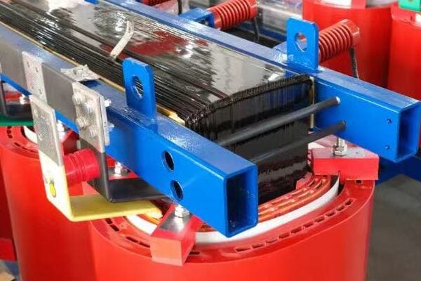
In this guide, I’ll walk you through the main fuse types available on the market, their core features, typical applications, and how to confidently choose the right one for your project or product. Whether you’re a procurement manager, maintenance technician, or electrical engineer, understanding these differences is crucial for ensuring proper circuit protection and equipment safety.
Overview: Why Different Fuse Types Exist?
Have you ever wondered why there are so many different types of fuses? Or perhaps you’ve been confused about which fuse to use in a specific application? The variety of fuse types can be overwhelming, but there’s a good reason for this diversity.
Different fuse types exist because of the wide range of electrical protection needs across various industries and applications. Factors like voltage levels, current requirements, physical space constraints, and specific operating conditions necessitate specialized fuse designs. For example, automotive systems need compact, easily replaceable fuses, while industrial equipment requires high-capacity fuses that can handle large fault currents. The diversity in fuse types ensures optimal protection for each unique electrical system.
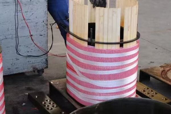
Key Factors Driving Fuse Diversity
Let’s explore the main reasons behind the variety of fuse types:
- Voltage and Current Ratings
- Physical Size and Installation Requirements
- Response Time and Interrupting Capacity
- Environmental Considerations
- Industry-Specific Standards
Voltage and Current Ratings
Meeting diverse electrical system needs:
- Low voltage DC for automotive (12-24V)
- Household AC (120-240V)
- Industrial power systems (up to 600V or higher)
I recall a project where we had to retrofit an old industrial control panel. The challenge was finding fuses that could handle the high voltage while fitting into the limited space of the existing fuseholders. This experience highlighted how crucial it is to have fuses designed for specific voltage and current ranges.
Physical Size and Installation Requirements
Adapting to various equipment designs:
- Compact blade fuses for automotive applications
- Cylindrical cartridge fuses for industrial panels
- Surface-mount fuses for printed circuit boards
During a recent electric vehicle design consultation, we had to balance the need for high-current protection with the limited space in the vehicle’s fuse box. This led us to choose specialized compact high-current fuses, showcasing how physical constraints drive fuse design innovation.
Response Time and Interrupting Capacity
Matching protection to load characteristics:
- Fast-acting fuses for sensitive electronics
- Time-delay fuses for motors with inrush currents
- High interrupting capacity for potential high fault currents
Here’s a quick comparison of fuse response characteristics:
| Fuse Type | Response Time | Typical Application |
|---|---|---|
| Fast-Acting | < 1 ms | Electronics, Semiconductors |
| Time-Delay | 10-30 ms | Motors, Transformers |
| Very Fast-Acting | < 0.1 ms | Power Semiconductors |
Environmental Considerations
Designing for specific operating conditions:
- High-temperature fuses for engine compartments
- Sealed fuses for outdoor or marine applications
- Vibration-resistant designs for mobile equipment
Industry-Specific Standards
Meeting regulatory and safety requirements:
- UL standards for North American markets
- IEC standards for international applications
- Specialized standards for automotive, aerospace, etc.
Key points about fuse type diversity:
- Voltage and current requirements vary widely across applications
- Physical size constraints necessitate different fuse form factors
- Load characteristics demand various response times and capacities
- Environmental factors influence fuse design and materials
- Industry standards drive specific fuse type developments
In my experience, understanding the reasons behind fuse diversity is crucial for proper selection. I once consulted on a solar power installation where the initial design used standard AC fuses for DC circuits. This oversight could have led to dangerous arcing in fault conditions. By explaining the need for specialized DC fuses designed for photovoltaic systems, we ensured a safer and more reliable installation.
For example, in a recent smart home project, we had to integrate protection for both high-power appliances and sensitive IoT devices. This required a mix of fuse types, from robust time-delay fuses for HVAC systems to ultra-fast, low-current fuses for smart sensors. This diversity in a single application underscores why different fuse types are not just useful, but essential for comprehensive electrical protection.
As we move on to discuss specific fuse types in detail, keep in mind that each type has been developed to address particular protection needs. Understanding these nuances is key to selecting the right fuse for your application.
Cartridge Fuses: Reliable Protection for High-Current Circuits?
Have you ever wondered what protects large industrial machines or power distribution panels from electrical overloads? Or perhaps you’ve seen those cylindrical fuses in your home’s main electrical panel and wondered why they’re shaped that way? Cartridge fuses play a crucial role in high-current circuit protection, but what makes them so reliable?
Cartridge fuses are cylindrical protective devices designed for high-current and high-voltage applications. They consist of a fuse element enclosed in a ceramic or glass body with metal end caps. These fuses offer high interrupting capacity, typically up to 200kA or more, making them ideal for industrial and commercial power systems. Cartridge fuses come in various sizes and ratings, from small 1/4" x 1-1/4" glass fuses for household use to large 3" x 15" fuses for industrial applications. Their robust construction and standardized dimensions make them reliable and easy to replace in a wide range of electrical systems.
Key Aspects of Cartridge Fuses
Let’s explore the main features and applications of cartridge fuses:
- Structure and Design
- Types and Ratings
- Applications in Various Industries
- Advantages and Limitations
- Installation and Replacement Considerations
Structure and Design
The anatomy of a cartridge fuse:
- Ceramic or glass body for insulation and arc suppression
- Metal end caps for electrical contact
- Internal fuse element (usually silver or copper)
- Sand or other arc-quenching material (in some types)
I recently had the opportunity to dissect a blown cartridge fuse during a training session. The intricate design of the fuse element and the way it was surrounded by arc-quenching material really highlighted the engineering that goes into these seemingly simple devices.
Types and Ratings
Variety to meet different needs:
- Voltage ratings from 250V to 600V AC (or higher for special types)
- Current ratings from less than 1A to over 1000A
- Time-delay or fast-acting characteristics
- Class designations (e.g., Class CC, J, L) for specific applications
During a recent industrial automation project, we had to carefully select cartridge fuses for motor protection. The challenge was finding fuses that could handle the motor’s startup current without nuisance tripping, while still providing fast protection against short circuits. This experience underscored the importance of understanding different fuse characteristics.
Applications in Various Industries
Wide range of uses:
- Industrial control panels and motor circuits
- Commercial and residential electrical distribution
- HVAC systems and large appliances
- Renewable energy systems (solar, wind)
Here’s a quick reference for common cartridge fuse applications:
| Industry | Typical Application | Fuse Class | Current Range |
|---|---|---|---|
| Industrial | Motor Protection | Class RK5 | 1-600A |
| Commercial | Main Distribution | Class J | 1-600A |
| Residential | Service Entrance | Class T | 1-1200A |
| Renewable Energy | Solar Inverters | Class gPV | 1-400A |
Advantages and Limitations
Weighing the pros and cons:
- Advantages: High interrupting capacity, wide range of ratings, robust construction
- Limitations: One-time use, can be larger than some alternatives
Installation and Replacement Considerations
Ensuring proper use and maintenance:
- Importance of using the correct fuse class and rating
- Safety procedures for fuse replacement
- Considerations for fuse coordination in a system
Key points about cartridge fuses:
- They offer high interrupting capacity for industrial applications
- Various types and ratings are available for different needs
- Cartridge fuses are used across multiple industries
- They provide reliable protection but are one-time use devices
- Proper selection and installation are crucial for effective protection
In my experience, the versatility of cartridge fuses makes them indispensable in many electrical systems. I recall a project where we were upgrading an old factory’s electrical system. The existing fuses were a mix of outdated types, some of which were no longer manufactured. By standardizing on modern cartridge fuses, we not only improved the system’s safety and reliability but also simplified maintenance and replacement procedures for the facility staff.
For example, in a recent data center project, we implemented a tiered protection scheme using different classes of cartridge fuses. Class L fuses protected the main feeders, while Class J fuses safeguarded branch circuits. This approach allowed for excellent coordination between protective devices, ensuring that faults were isolated at the lowest possible level, minimizing disruption to the data center’s critical operations.
As we move on to discuss blade fuses, remember that while cartridge fuses excel in high-current applications, each fuse type has its own strengths and ideal use cases. Understanding these differences is key to designing safe and efficient electrical systems.
Blade Fuses: Compact and Standardized for Automotive Use?
Have you ever popped the hood of your car and noticed those colorful plastic components in the fuse box? Or perhaps you’ve had to replace a fuse in your vehicle and were surprised by its small, flat design? These are blade fuses, but what makes them so well-suited for automotive applications?
Blade fuses are compact, plug-in style fuses primarily used in automotive electrical systems. They feature a plastic housing with two prong-like terminals and a visible fusible link. Blade fuses are color-coded for easy identification of their amperage rating, ranging typically from 2A to 40A. Their standardized design allows for quick, tool-free replacement and compact fuse box layouts. While primarily used in vehicles, blade fuses have also found applications in marine, recreational vehicles, and some small appliances due to their reliability and ease of use in low-voltage DC systems.
Key Aspects of Blade Fuses
Let’s explore the main features and applications of blade fuses:
- Design and Construction
- Types and Ratings
- Advantages in Automotive Applications
- Color Coding System
- Installation and Troubleshooting
Design and Construction
The anatomy of a blade fuse:
- Plastic housing for insulation and color coding
- Two blade-like terminals for easy insertion and removal
- Visible fusible link for quick inspection
- Compact, space-saving design
I remember the first time I worked on a car’s electrical system as a young engineer. The simplicity and accessibility of blade fuses made the task much less daunting than I had anticipated. This experience really highlighted the user-friendly design of these components.
Types and Ratings
Variety to meet different automotive needs:
- Standard blade fuses (ATO/ATC): Most common type
- Mini blade fuses: For tight spaces in modern vehicles
- Maxi blade fuses: For higher current applications
- Current ratings typically from 2A to 40A (up to 100A for some maxi types)
- Voltage rating usually 32V DC
During a recent electric vehicle (EV) design consultation, we had to carefully select blade fuses for various circuits. The challenge was balancing the need for higher current capacities in some EV-specific systems while maintaining compatibility with standard automotive fuse boxes. This project showcased the evolving needs in automotive electrical protection.
Advantages in Automotive Applications
Why blade fuses excel in vehicles:
- Compact size allows for dense fuse box layouts
- Easy to inspect and replace without tools
- Resistant to vibration and temperature fluctuations
- Standardized design across manufacturers
Here’s a quick comparison of common blade fuse types:
| Type | Size (mm) | Current Range | Typical Use |
|---|---|---|---|
| Mini | 10.9 x 3.6 | 2A – 30A | Modern vehicles, tight spaces |
| Standard (ATO) | 19.1 x 5.1 | 2A – 40A | Most automotive applications |
| Maxi | 29.2 x 8.5 | 20A – 100A | High-current vehicle systems |
Color Coding System
Simplifying identification and replacement:
- Each amperage rating has a specific color
- Universal across manufacturers for easy identification
- Ranges from gray (2A) to orange (40A) in standard types
Installation and Troubleshooting
Ensuring proper use and maintenance:
- Importance of using the correct amperage rating
- How to safely check and replace blade fuses
- Common signs of electrical issues in automotive systems
Key points about blade fuses:
- They are designed specifically for automotive electrical systems
- Blade fuses come in various sizes for different current needs
- Their compact and standardized design offers many advantages in vehicles
- Color coding simplifies identification and replacement
- Proper selection and installation are crucial for vehicle electrical safety
In my experience, the standardization of blade fuses has greatly simplified automotive electrical maintenance. I recall a project where we were retrofitting classic cars with modern electrical systems. The switch to blade fuses not only improved reliability but also made it much easier for owners to perform basic electrical troubleshooting and maintenance.
For example, in a recent marine electrical system design, we adapted automotive-style blade fuses for use in boats. The compact size and ease of replacement made them ideal for the tight spaces in marine applications. We even implemented a custom fuse box design that maintained the benefits of blade fuses while ensuring protection against the corrosive marine environment.
As we move on to discuss resettable fuses, remember that while blade fuses are primarily associated with automotive use, their design principles of compactness and ease of use have influenced other areas of electrical protection as well.
Resettable Fuses (PTC): Smart Reusability for Consumer Electronics?
Have you ever wondered why some electronic devices seem to recover on their own after an electrical fault? Or perhaps you’ve heard of "self-healing" circuits and wondered how they work? Resettable fuses, also known as polymeric positive temperature coefficient (PTC) devices, are behind this smart protection. But what makes them so unique and suitable for consumer electronics?
Resettable fuses, or PTC devices, are polymer-based components that increase their resistance dramatically when heated by excessive current. Unlike traditional fuses, they don’t need replacement after activation. Once the fault is cleared and power removed, they cool down and return to a low-resistance state. This self-resetting feature makes them ideal for consumer electronics, USB ports, and battery protection circuits. PTC fuses typically handle currents from a few milliamps to several amps and voltages up to 60V, providing reliable, maintenance-free protection for low-power circuits.
Key Aspects of Resettable Fuses
Let’s explore the main features and applications of PTC fuses:
- Working Principle
- Types and Ratings
- Advantages in Consumer Electronics
- Limitations and Considerations
- Common Applications
Working Principle
How PTC fuses protect circuits:
- Normal state: Low resistance, allows current flow
- Fault condition: Heats up, resistance increases dramatically
- After fault: Cools down, returns to low resistance state
I remember being fascinated when I first encountered a PTC fuse in a lab setting. Watching it react to an overcurrent condition and then reset itself seemed almost magical, especially compared to traditional fuses.
Types and Ratings
Variety to meet different protection needs:
- Radial leaded PTCs for through-hole PCB mounting
- Surface mount PTCs for compact designs
- Strap PTCs for higher current applications
- Current ratings typically from 50mA to 9A
- Voltage ratings usually up to 60V (some special types go higher)During a recent project designing a power bank, we had to carefully select PTC fuses for each USB port. The challenge was finding devices that could handle the normal charging current but react quickly to potential short circuits from damaged cables. This experience highlighted the importance of understanding both the steady-state and trip characteristics of PTC fuses.
Advantages in Consumer Electronics
Why PTC fuses excel in modern devices:
- Self-resetting capability reduces maintenance
- No need for fuse replacement, improving user experience
- Can handle repeated fault conditions
- Compact size ideal for crowded PCBs
Here’s a quick comparison of PTC fuses with traditional fuses:
| Aspect | PTC Fuse | Traditional Fuse |
|---|---|---|
| Reusability | Self-resetting | One-time use |
| Size | Very compact | Varies, often larger |
| Response to Faults | Gradual resistance increase | Immediate open circuit |
| Typical Applications | USB ports, battery packs | High power circuits |
| Current Range | mA to few A | mA to hundreds of A |
Limitations and Considerations
Understanding the trade-offs:
- Higher resistance in normal operation compared to traditional fuses
- Response time can be slower than fast-acting traditional fuses
- Limited to lower voltage and current applications
- Performance can be affected by ambient temperature
Common Applications
Where you’ll find PTC fuses:
- USB ports and computer peripherals
- Rechargeable battery packs
- Automotive sensor circuits
- Audio equipment
- Telecom line protection
Key points about resettable fuses:
- They provide self-resetting protection for low-power circuits
- PTC fuses are ideal for repeated fault conditions
- Their compact size is perfect for modern electronic devices
- They offer maintenance-free protection, improving user experience
- PTC fuses have limitations in high-power applications
In my experience, the adoption of PTC fuses has significantly improved the reliability and user-friendliness of many consumer devices. I recall a project where we were redesigning a line of portable speakers. By replacing traditional fuses with PTCs, we not only reduced warranty claims due to blown fuses but also eliminated the need for users to ever replace a fuse, greatly enhancing the product’s perceived quality and ease of use.
For example, in a recent IoT device development, we implemented PTC fuses in various sensing circuits. This choice allowed the device to recover from temporary fault conditions automatically, ensuring continuous operation in remote deployments where manual resets would be impractical. The self-resetting nature of PTCs proved crucial in maintaining the reliability of the distributed sensor network.
As we move on to discuss other specialized fuses, remember that while PTC fuses excel in low-power, consumer-oriented applications, each fuse type has its own niche where it provides optimal protection. Understanding these specializations is key to designing robust and reliable electrical systems across various industries.
Other Specialized Fuses: High-Voltage, SMD, and Drop-Out Fuses?
Have you ever wondered how massive power transformers are protected from electrical faults? Or perhaps you’ve looked at a tiny smartphone circuit board and wondered how such miniature components can provide overcurrent protection? The world of specialized fuses extends far beyond the common types we’ve discussed, addressing unique protection needs across various industries. But what makes these specialized fuses so crucial in their respective applications?
Specialized fuses cater to specific protection requirements in diverse electrical systems. High-voltage fuses, designed for voltages from 1kV to over 100kV, protect power distribution equipment. Surface Mount Device (SMD) fuses, incredibly small and suitable for automated assembly, safeguard densely packed electronic circuits. Drop-out fuses, used in overhead power lines, provide visible indication of operation and easy replacement. Each type offers unique features like extreme voltage handling, miniaturization, or specific operational characteristics, making them indispensable in their respective fields of application.
Key Types of Specialized Fuses
Let’s explore some of the most important specialized fuse types:
- High-Voltage Fuses
- Surface Mount Device (SMD) Fuses
- Drop-Out Fuses
- Semiconductor Fuses
- Photovoltaic (PV) Fuses
High-Voltage Fuses
Protecting power distribution systems:
- Designed for voltages from 1kV to over 100kV
- Used in transformer protection, switchgear, and power factor correction equipment
- Capable of interrupting extremely high fault currents
I once visited a high-voltage substation where I saw these massive fuses in action. The sheer size and engineering behind these devices, designed to safely interrupt fault currents that could power a small city, was awe-inspiring.
Surface Mount Device (SMD) Fuses
Miniature protection for modern electronics:
- Extremely small, suitable for densely packed PCBs
- Available in various package sizes (e.g., 0603, 1206)
- Used in smartphones, tablets, and other compact electronic devices
During a recent smartphone design project, the challenge of fitting adequate protection into an incredibly tight space really highlighted the importance of SMD fuses. Their miniature size allowed us to implement robust protection without compromising the sleek design of the device.
Drop-Out Fuses
Visible protection for overhead power lines:
- Designed to physically "drop out" when activated
- Provides clear visual indication of operation
- Easily replaceable from the ground using hot sticks
Here’s a quick comparison of these specialized fuse types:
| Fuse Type | Voltage Range | Key Feature | Typical Application |
|---|---|---|---|
| High-Voltage | 1kV – 100kV+ | Extreme interrupting capacity | Power transformers |
| SMD | Up to 250V | Ultra-compact size | Smartphones, wearables |
| Drop-Out | 11kV – 33kV | Visible operation | Overhead power lines |
| Semiconductor | Up to 1500V | Ultra-fast acting | Power electronics |
| PV | Up to 1500V DC | DC current interruption | Solar panel arrays |
Semiconductor Fuses
Protecting sensitive power electronics:
- Ultra-fast acting to protect semiconductors like thyristors and IGBTs
- Designed to operate before the semiconductor device is damaged
- Used in inverters, motor drives, and power conversion equipment
Photovoltaic (PV) Fuses
Safeguarding solar power systems:
- Specifically designed for DC circuits in solar installations
- Capable of interrupting DC arcs, which are more persistent than AC
- Used in combiner boxes, inverters, and battery systems in solar setups
Key points about specialized fuses:
- High-voltage fuses protect critical power distribution equipment
- SMD fuses enable protection in extremely compact electronic devices
- Drop-out fuses offer easy visual inspection and replacement in overhead lines
- Semiconductor fuses provide ultra-fast protection for sensitive electronics
- PV fuses are crucial for the safety of solar power systems
In my experience, the importance of these specialized fuses often becomes most apparent in extreme situations. I recall a project involving a large solar farm where standard DC fuses were initially specified. After a thorough risk assessment, we switched to specialized PV fuses. This decision proved crucial when a severe weather event caused multiple fault conditions across the array. The PV fuses successfully prevented what could have been a catastrophic failure, showcasing the value of application-specific protection.
For example, in a recent industrial automation project, we implemented semiconductor fuses to protect high-speed switching circuits in motor drives. The ultra-fast response of these fuses was critical in preventing damage to expensive IGBT modules during fault conditions, significantly reducing downtime and replacement costs for the facility.
As we conclude our overview of fuse types, it’s clear that the world of electrical protection is diverse and specialized. Each fuse type, from the common cartridge fuse to the highly specialized PV fuse, plays a crucial role in ensuring the safety and reliability of electrical systems across various industries and applications.
How to Select the Right Fuse Type for Your Application?
Are you feeling overwhelmed by the variety of fuse options available for your project? Or perhaps you’re unsure about which factors are most critical when choosing a fuse? Selecting the right fuse is crucial for ensuring the safety and reliability of your electrical system, but with so many types and specifications, how can you be confident in your choice?
Selecting the right fuse involves considering several key factors: voltage rating, current rating, interrupting capacity, response time, and physical size. First, match the fuse’s voltage rating to your system’s voltage. Then, choose a current rating slightly above the circuit’s normal operating current. Consider the potential fault current to ensure adequate interrupting capacity. Determine if you need a fast-acting or time-delay response. Finally, ensure the fuse’s physical size and type are compatible with your installation. Always consult manufacturer specifications and relevant electrical codes for precise selection.
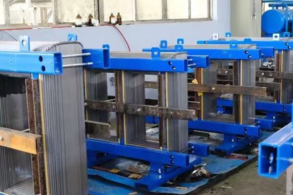
Key Steps in Fuse Selection
Let’s break down the process of choosing the right fuse:
- Determine System Voltage and Current
- Consider Potential Fault Current
- Evaluate Response Time Needs
- Account for Environmental Factors
- Check Physical Compatibility
Determine System Voltage and Current
Matching fuse ratings to your system:
- Voltage rating must be equal to or greater than system voltage
- Current rating typically 125% of maximum continuous current
- Consider both normal operation and startup conditions
I recently consulted on a project where the initial fuse selection was causing nuisance tripping. By carefully analyzing the load profile, including inrush currents, we were able to select fuses that provided proper protection without unnecessary interruptions.
Consider Potential Fault Current
Ensuring adequate interrupting capacity:
- Determine the maximum potential fault current at the fuse location
- Choose a fuse with an interrupting rating higher than this value
- Consider both AC and DC interrupting capacities for DC applications
During a recent industrial power system upgrade, we had to recalculate fault currents due to changes in the utility supply. This led to upgrading several fuses to higher interrupting capacity models, ensuring the system remained protected under the new conditions.
Evaluate Response Time Needs
Matching fuse characteristics to load behavior:
- Fast-acting fuses for sensitive electronics and semiconductor protection
- Time-delay fuses for motors and other high inrush current loads
- Consider coordination with other protective devices
Here’s a quick guide for choosing fuse response times:
| Load Type | Recommended Fuse Response | Reason |
|---|---|---|
| Electronics | Fast-acting | Sensitive components need quick protection |
| Motors | Time-delay | Allows for startup inrush current |
| Lighting | Fast-acting or Time-delay | Depends on type (LED vs. HID) |
| General Purpose | Dual-element | Balances fast short circuit and overload protection |
Account for Environmental Factors
Adapting to operating conditions:
- Temperature derating for high ambient temperatures
- Vibration resistance for mobile or industrial applications
- Moisture and corrosion resistance for outdoor installations
Check Physical Compatibility
Ensuring proper fit and installation:
- Verify fuse size matches holder or clip dimensions
- Consider accessibility for maintenance and replacement
- Check for any special mounting requirements
Key points for fuse selection:
- Match voltage and current ratings to your system requirements
- Ensure adequate interrupting capacity for potential fault currents
- Choose appropriate response time based on load characteristics
- Consider environmental factors that may affect fuse performance
- Verify physical compatibility with your installation
In my experience, thorough fuse selection often requires looking beyond basic ratings. I recall a project involving a critical process control system where standard fuses were initially specified. After a detailed analysis of the potential consequences of downtime, we opted for an upgraded fuse type with indicator features. This choice not only provided better protection but also allowed for quicker troubleshooting, significantly reducing potential downtime costs.
For example, in a recent renewable energy project, we had to select fuses for a hybrid solar-wind system. This required careful consideration of both AC and DC protection needs, varying environmental conditions, and the need for easy maintenance in remote locations. By meticulously evaluating each factor, we developed a comprehensive protection scheme that ensured reliable operation across diverse operating conditions.
As we move on to discuss recommended fuse models and suppliers, remember that proper fuse selection is not just about meeting minimum specifications—it’s about optimizing protection for your specific application to ensure safety, reliability, and efficiency.
Recommended Fuse Models and Suppliers from China?
Are you looking for reliable fuse suppliers for your next project? Or perhaps you’re wondering which specific fuse models are best suited for common applications? Sourcing the right fuses from reputable manufacturers is crucial for ensuring the quality and reliability of your electrical protection. But with so many options available, how can you identify the best choices?
When sourcing fuses from China, consider reputable manufacturers like CHBEB, CHINT, and TBEA. For industrial applications, CHBEB’s NT00 series (500V/100A) cartridge fuses are excellent for control panels. CHINT’s NH2 blade fuses (32V/30A) are ideal for automotive use. For utility-scale applications, TBEA’s 11kV/100A dropout fuses are well-suited for transformer protection. These manufacturers offer a range of fuses meeting international standards like IEC and UL, ensuring quality and reliability. Always verify certifications and test reports when selecting fuses for critical applications.
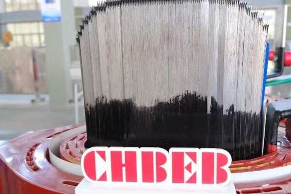
Recommended Fuse Models and Suppliers
Let’s explore some top fuse options from Chinese manufacturers:
- CHBEB Fuse Models
- CHINT Electric Offerings
- TBEA Fuse Products
- Comparison of Key Features
- Considerations When Sourcing from China
CHBEB Fuse Models
Specializing in industrial and power distribution fuses:
- CHBEB-NT00 Series: 500V/100A cartridge fuses for industrial control panels
- CHBEB-PV1000 Series: 1000VDC/30A fuses for solar applications
- CHBEB-SMD Series: Surface mount fuses for electronics manufacturing
I recently specified CHBEB-NT00 fuses for a large industrial automation project. Their high interrupting capacity and reliable performance were crucial in ensuring the safety of the control systems.
CHINT Electric Offerings
Known for a wide range of electrical components:
- CHINT NH2 Blade Fuses: 32V/30A for automotive and low-voltage DC systems
- CHINT RT14 Series: Time-delay fuses for motor protection
- CHINT NM1 Series: Miniature circuit breaker alternative to traditional fuses
During a recent electric vehicle charging station project, we utilized CHINT NH2 blade fuses for the low-voltage distribution system. Their standardized design and reliable performance made them an excellent choice for this application.
TBEA Fuse Products
Excelling in high-voltage and utility-scale fuses:
- TBEA Dropout 11kV/100A: Ideal for overhead distribution transformer protection
- TBEA HV Fuse Links: For high-voltage switchgear and transformer applications
- TBEA DC Fuses: Specialized for HVDC transmission systems
Here’s a comparison of recommended fuse models:
| Model | Type | Voltage/Current | Best For | Available From |
|---|---|---|---|---|
| CHBEB-NT00 | Cartridge | 500V/100A | Industrial control panels | CHBEB |
| CHINT NH2 | Blade | 32V/30A | Automotive, Low-voltage DC | CHINT |
| TBEA Dropout | High-voltage | 11kV/100A | Utility transformer protection | TBEA |
| CHBEB-PV1000 | Solar | 1000VDC/30A | Photovoltaic systems | CHBEB |
| CHINT RT14 | Time-delay | 690V/32A | Motor circuits | CHINT |
Comparison of Key Features
Evaluating crucial aspects:
- Compliance with international standards (IEC, UL, etc.)
- Availability of technical support and documentation
- Range of ratings and sizes available
- Special features (e.g., indicator flags, high breaking capacity)
Considerations When Sourcing from China
Ensuring quality and reliability:
- Verify manufacturer certifications and test reports
- Consider lead times and minimum order quantities
- Evaluate after-sales support and warranty terms
- Be aware of potential communication and shipping challenges
Key points about sourcing fuses from China:
- CHBEB offers reliable options for industrial and power distribution applications
- CHINT provides a wide range of fuses for various low-voltage applications
- TBEA specializes in high-voltage and utility-scale fuse solutions
- Verify compliance with relevant standards when selecting fuses
- Consider factors beyond price, such as support and reliability, when sourcing
In my experience, successful sourcing of fuses from China requires careful evaluation beyond just specifications and price. I recall a project where we initially chose fuses based primarily on cost. However, after experiencing inconsistent quality and poorafter-sales support, we switched to a slightly more expensive but more reliable supplier. This decision ultimately saved time and money by reducing downtime and replacement costs.
For example, in a recent large-scale solar farm project, we sourced specialized PV fuses from CHBEB. Their ability to provide detailed technical documentation and support throughout the design phase was crucial. When we encountered an unexpected issue during installation, their responsive technical team helped us quickly resolve the problem, minimizing project delays.
As we move on to address some frequently asked questions about choosing and using different fuse types, remember that while price is important, factors like reliability, support, and long-term performance should be key considerations in your fuse selection and sourcing decisions.
FAQs: Choosing and Using Different Fuse Types?
Are you still unsure about some aspects of fuse selection and usage? You’re not alone. Many engineers and technicians have questions when it comes to choosing and applying different fuse types. Let’s address some of the most common queries to help clarify your understanding and improve your fuse selection process.
Choosing and using the right fuse type involves understanding their differences, applications, and limitations. Key considerations include the electrical characteristics of your circuit, environmental factors, and specific protection needs. Proper fuse selection ensures optimal protection, while incorrect choices can lead to equipment damage or safety hazards. It’s crucial to match the fuse type to your application, considering factors like voltage, current, interrupting capacity, and response time. Always consult manufacturer specifications and relevant electrical codes for the most accurate guidance.

Frequently Asked Questions About Fuses
Let’s address some common questions about choosing and using different fuse types:
- What is the difference between cartridge and blade fuses?
- Can I replace a glass fuse with a blade fuse?
- When should I use a resettable fuse instead of a standard fuse?
- What fuse is used in 11kV transformers?
- How do I know if a fuse is blown?
What is the difference between cartridge and blade fuses?
Understanding the key distinctions:
- Cartridge fuses: Cylindrical design, higher voltage and current ratings, used in industrial and high-power applications
- Blade fuses: Flat, plug-in design, lower ratings, primarily used in automotive and low-voltage DC systems
I once had to explain this difference to a client who was confused about why we couldn’t use automotive-style blade fuses in their industrial control panel. Demonstrating the higher voltage and interrupting capacity of cartridge fuses helped them understand the importance of using the right fuse type for each application.
Can I replace a glass fuse with a blade fuse?
Addressing compatibility concerns:
- Generally not recommended due to differences in size, ratings, and mounting
- Glass fuses are typically used in household appliances and electronics
- Blade fuses are designed for automotive systems with different voltage and current characteristics
During a recent DIY electronics workshop, a participant asked about substituting a blade fuse for a glass fuse in their project. I explained that while it might physically fit, the electrical characteristics and protection level would likely be inappropriate, potentially leading to inadequate protection or nuisance tripping.
When should I use a resettable fuse instead of a standard fuse?
Choosing between one-time and resettable protection:
- Resettable fuses (PTCs) are ideal for:
- Frequent overcurrent events (e.g., USB ports)
- Hard-to-access locations where replacement is difficult
- Consumer electronics where user-serviceability is not desired
- Standard fuses are better for:
- High-current applications
- Situations requiring a definite open circuit after a fault
Here’s a quick comparison:
| Aspect | Resettable Fuse (PTC) | Standard Fuse |
|---|---|---|
| Reusability | Self-resetting | One-time use |
| Current Range | Typically < 9A | mA to 1000s of A |
| Response Time | Generally slower | Can be very fast |
| Voltage Rating | Usually ≤ 60V | Up to kV range |
| Best For | Low-power electronics | Wide range of applications |
What fuse is used in 11kV transformers?
Protecting high-voltage equipment:
- Typically, high-voltage fuses or dropout fuses are used
- Examples include expulsion fuses or current-limiting fuses designed for 11kV systems
- Often part of a coordinated protection scheme with other devices
I recently worked on an 11kV substation upgrade where we implemented a combination of high-voltage fuses for transformer protection and reclosers for line protection. This layered approach provided comprehensive protection while allowing for temporary faults to clear without permanent interruption.
How do I know if a fuse is blown?
Identifying a failed fuse:
- Visual inspection: Look for a broken filament in glass fuses or a tripped indicator in some cartridge fuses
- Continuity test: Use a multimeter to check for an open circuit
- For blade fuses: Check for a broken metal strip visible through the plastic body
Key points about choosing and using fuses:
- Different fuse types are designed for specific applications and cannot always be interchanged
- Resettable fuses offer advantages in certain low-power, frequent-fault scenarios
- High-voltage applications require specialized fuses designed for those voltage levels
- Visual inspection and electrical testing can help identify blown fuses
- Always match the fuse type and rating to your specific application requirements
In my experience, understanding these nuances can prevent many common mistakes in fuse application. I recall a project where a maintenance team was repeatedly replacing blown fuses in a motor circuit. Upon investigation, we discovered they were using fast-acting fuses instead of time-delay types, causing nuisance trips during motor startup. Switching to the correct fuse type resolved the issue and improved system reliability.
For example, in a recent smart home installation, we opted for resettable PTCs in several low-current circuits prone to occasional overloads. This choice eliminated the need for homeowners to replace fuses, enhancing the system’s user-friendliness and reducing maintenance calls.
Conclusion
Understanding the various types of fuses and their applications is crucial for designing safe and reliable electrical systems. From cartridge fuses in industrial settings to blade fuses in automotive applications, and from resettable PTCs in consumer electronics to specialized high-voltage fuses in power distribution, each type serves a specific purpose. Proper selection and application of fuses ensure optimal protection against overcurrent conditions, enhancing safety and equipment longevity across diverse electrical systems.
Thank you for joining me in this exploration of fuse types and their applications. Stay curious, stay informed, and let’s keep pushing the boundaries of what’s possible in power distribution and electrical engineering.
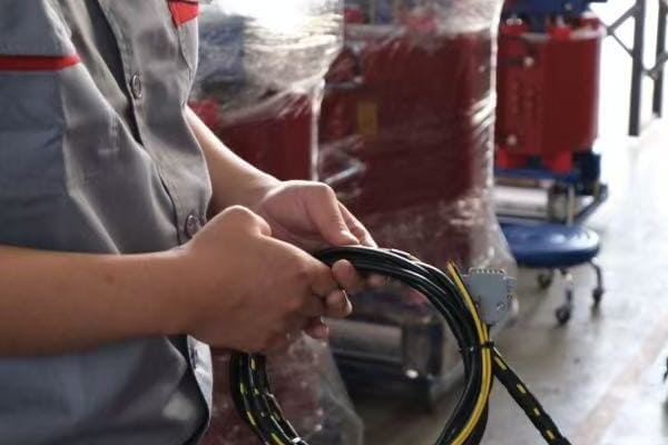
Every electrical circuit—whether it powers your home, an industrial machine, or a vehicle—needs protection from overcurrent. That’s where a fuse comes in. It’s a simple, inexpensive component, but its role is crucial: preventing equipment damage, fire hazards, or even fatal accidents by cutting off electricity when something goes wrong.
A fuse is a safety device in electrical circuits that protects against overcurrent. It contains a metal wire or strip that melts when excessive current flows through it, breaking the circuit and preventing damage to equipment. Fuses are essential for safeguarding against short circuits, overloads, and other electrical faults in various applications, from household appliances to industrial machinery and vehicles.

In this guide, I’ll explain what fuses are, how they work, and why they’re so important in electrical systems. Whether you’re a beginner trying to understand basic electrical concepts, a homeowner curious about your home’s electrical safety, or a procurement specialist looking to choose the right fuses for your project, this article will provide you with clear, practical information about these crucial safety devices.
What Is a Fuse? A Simple Definition for Beginners?
Have you ever wondered what protects your electrical devices from sudden power surges? Or why some appliances stop working after a lightning storm? The answer often lies in a small but crucial component called a fuse. But what exactly is a fuse, and how does it keep your electronics safe?
A fuse is a simple safety device that acts as a weak link in an electrical circuit. It’s designed to ‘blow’ or melt when too much current flows through it, breaking the circuit and stopping the flow of electricity. This protective action prevents damage to other components in the circuit, potentially saving expensive equipment and preventing electrical fires. Fuses are like the circuit’s ‘safety valves’, sacrificing themselves to protect the rest of the system.
Key Aspects of Fuses
Let’s break down the main elements of a fuse:
- Structure and Components
- Basic Function
- Types of Fuses
- Importance in Electrical Safety
Structure and Components
The anatomy of a fuse:
- Metal wire or strip (the fusible element)
- Enclosure (glass, ceramic, or plastic)
- Terminals for connection to the circuit
I remember the first time I opened a blown glass fuse as a curious engineering student. The sight of that thin, melted wire inside really drove home how simple yet effective this safety device is.
Basic Function
How a fuse protects your circuit:
- Conducts electricity under normal conditions
- Melts when current exceeds rated value
- Creates an open circuit, stopping current flow
During a recent home renovation project, I explained to the homeowner how the fuse in their old fuse box was like a ‘sacrificial’ component, protecting the rest of their electrical system by failing first under dangerous conditions.
Types of Fuses
Common fuse varieties:
- Glass tube fuses (common in household appliances)
- Blade fuses (used in automotive applications)
- Cartridge fuses (found in industrial settings)
Here’s a quick comparison of common fuse types:
| Fuse Type | Typical Application | Current Range | Advantages |
|---|---|---|---|
| Glass Tube | Home appliances | 0.1A – 20A | Easy to inspect |
| Blade | Automotive | 1A – 100A | Compact, color-coded |
| Cartridge | Industrial | 0.1A – 600A | High interrupting capacity |
Importance in Electrical Safety
Why fuses are crucial:
- Prevent equipment damage from overcurrent
- Reduce fire risk in electrical systems
- Provide a visible indication of electrical faults
Key points about fuses:
- They are simple devices with a critical safety function
- Fuses work by melting when exposed to excessive current
- Different types of fuses suit various applications
- They are the first line of defense in electrical safety
In my experience, understanding the basic concept of a fuse can significantly enhance one’s appreciation for electrical safety. I once worked on a project where a client insisted on using oversized fuses to prevent frequent ‘nuisance’ blowing. I had to explain that this practice defeated the fuse’s purpose and could lead to dangerous situations. It was a crucial lesson in respecting the role of these small but vital components.
For example, in a recent industrial automation project, we carefully selected fuses for each circuit based on the specific loads and potential fault currents. This meticulous approach not only ensured the safety of the expensive equipment but also improved the overall reliability of the system by providing targeted protection for each component.
As we move on to discuss how fuses work in more detail, remember that these simple devices play a critical role in the safety and reliability of every electrical system you encounter, from your smartphone charger to massive industrial machinery.
How Does a Fuse Work in an Electrical Circuit?
Have you ever wondered what happens inside a fuse when it ‘blows’? Or why some fuses seem to react faster than others to electrical problems? Understanding the working principle of a fuse can help you appreciate its crucial role in protecting your electrical devices and systems.
A fuse works by utilizing a metal wire or strip designed to melt when the current flowing through it exceeds a specific threshold. Under normal conditions, this wire conducts electricity without issue. However, when excessive current flows—due to a short circuit or overload—the wire heats up rapidly and melts, creating an open circuit. This action interrupts the current flow, protecting the rest of the circuit from damage. The fuse essentially acts as a ‘weak link’ that fails safely before other components can be harmed.

Key Aspects of Fuse Operation
Let’s explore the main elements of how a fuse functions:
- Current Flow and Heat Generation
- Melting Point and Time-Current Characteristics
- Circuit Interruption Process
- Factors Affecting Fuse Performance
Current Flow and Heat Generation
The physics behind fuse operation:
- Electric current produces heat in the fuse element (I²R heating)
- Heat accumulates faster as current increases
- The fuse element is designed to melt at a specific temperature
I recall demonstrating this principle in a lab using a thin wire and gradually increasing current. The moment when the wire suddenly glowed bright red and then vaporized was a powerful visual lesson in how fuses protect circuits.
Melting Point and Time-Current Characteristics
How fuses respond to different overcurrent situations:
- Fast-acting fuses melt quickly under short circuits
- Time-delay fuses can withstand temporary overloads
- Fuse ratings indicate both current capacity and response time
During a recent industrial project, we had to carefully select fuses with the right time-current characteristics to protect motors that had high startup currents but needed protection against sustained overloads.
Circuit Interruption Process
What happens when a fuse ‘blows’:
- The fuse element melts, creating a gap
- An arc may form briefly across the gap
- The arc is extinguished, fully interrupting the circuit
Here’s a simplified view of the fuse operation process:
| Stage | Current Level | Fuse Element State | Circuit Status |
|---|---|---|---|
| Normal Operation | At or below rated | Solid, conducting | Closed |
| Overload Detected | Above rated | Heating up | Closed |
| Fuse Blows | Excessive | Melting/Vaporizing | Opening |
| Circuit Protected | Zero | Fully melted, gap formed | Open |
Factors Affecting Fuse Performance
Elements that influence how a fuse operates:
- Ambient temperature can affect fuse ratings
- Cycling loads may cause fatigue in the fuse element
- Altitude can impact a fuse’s ability to quench arcs
Key points about fuse operation:
- Fuses work based on the heating effect of electric current
- Different fuse types have varying response characteristics
- The fuse interruption process involves melting and arc extinction
- Environmental and operational factors can affect fuse performance
In my experience, understanding the nuances of fuse operation is crucial for proper application. I once consulted on a project where frequent fuse blowing in a critical system was causing significant downtime. By analyzing the load characteristics and fuse response times, we discovered that the fuses were slightly undersized for the normal operational spikes. Upgrading to properly rated, time-delay fuses solved the issue, improving system reliability dramatically.
For example, in a recent solar power installation, we had to account for the unique current characteristics of photovoltaic systems. We selected specialized DC fuses designed to handle the constant current nature of solar panels and the potential for reverse currents. This choice was crucial in ensuring the long-term safety and efficiency of the installation.
As we move on to discuss why fuses are essential for equipment safety, keep in mind that the seemingly simple operation of a fuse is the result of careful engineering, designed to provide reliable protection in a wide range of electrical applications.
Why Fuses Are Essential for Equipment Safety?
Have you ever wondered why electrical systems always seem to include fuses, even in advanced modern devices? Or perhaps you’ve questioned whether fuses are really necessary given today’s sophisticated circuit designs? The truth is, fuses play a critical role in equipment safety that no other component can easily replace.
Fuses are essential for equipment safety because they provide a fast, reliable, and cost-effective way to protect against overcurrent conditions. They act as a ‘sacrificial’ component, failing safely before more expensive or critical parts can be damaged. Fuses prevent electrical fires, protect against short circuits, and help isolate faulty sections of a circuit. Their simplicity makes them highly reliable, and their ability to interrupt extremely high fault currents makes them indispensable in both low and high-power applications.
Key Reasons Fuses Are Essential
Let’s explore the main reasons why fuses are crucial for equipment safety:
- Overcurrent Protection
- Fire Prevention
- Equipment Longevity
- Fault Isolation
- Compliance with Safety Standards
Overcurrent Protection
Guarding against excessive current flow:
- Prevents damage from short circuits
- Protects against sustained overloads
- Responds quickly to dangerous current levels
I once investigated a case where a manufacturing line suffered repeated equipment failures. We discovered that a missing fuse in one section was allowing fault currents to propagate, damaging multiple machines. Installing the correct fuse resolved the issue, saving the company significant repair costs.
Fire Prevention
Reducing the risk of electrical fires:
- Interrupts current before wires can overheat
- Prevents insulation breakdown and arcing
- Acts as a last line of defense against electrical faults
During a home safety inspection, I found an improperly fused circuit that was warm to the touch. Explaining to the homeowner how this could have led to a fire really drove home the importance of proper fusing in electrical systems.
Equipment Longevity
Protecting investments in electrical equipment:
- Prevents damage from electrical stress
- Reduces wear on components from overcurrent events
- Helps maintain equipment within safe operating parameters
Here’s a comparison of protected vs unprotected equipment:
| Aspect | With Proper Fusing | Without Fusing |
|---|---|---|
| Lifespan | Extended | Potentially shortened |
| Failure Rate | Reduced | Increased |
| Repair Costs | Lower | Higher |
| Safety Risk | Minimized | Elevated |
Fault Isolation
Containing electrical problems:
- Limits damage to specific circuit sections
- Helps quickly identify problem areas
- Prevents cascading failures in complex systems
Compliance with Safety Standards
Meeting regulatory requirements:
- Essential for product certification (UL, CE, etc.)
- Required by electrical codes in most jurisdictions
- Necessary for insurance compliance in many settings
Key points about the importance of fuses:
- They provide critical protection against overcurrent events
- Fuses are essential in preventing electrical fires
- Proper fusing contributes to longer equipment life
- Fuses help isolate faults, limiting damage in complex systems
- Using appropriate fuses is often required for regulatory compliance
In my experience, the value of fuses in ensuring equipment safety cannot be overstated. I recall a project where a client was reluctant to invest in high-quality fuses for a new production line, viewing them as an unnecessary expense. We conducted a risk assessment that showed how the potential cost of equipment damage and downtime far outweighed the fuse investment. This analysis not only convinced the client but also led to a company-wide review of their fusing practices, ultimately enhancing their overall operational safety and reliability.
For example, in a recent data center project, we implemented a comprehensive fusing strategy that coordinated protection from the main input down to individual server racks. This layered approach not only protected the expensive equipment but also ensured that any electrical faults would be isolated to the smallest possible section, maximizing uptime for this critical facility.
As we move on to discuss common types of fuses and their applications, remember that choosing the right fuse is not just about meeting a specification—it’s about providing a crucial layer of safety that protects both equipment and people.
Common Types of Fuses and Their Applications?
Are you feeling overwhelmed by the variety of fuses available in the market? Or perhaps you’re wondering why there are so many different types and what makes each one unique? Understanding the common types of fuses and their specific applications can help you make informed decisions for your electrical projects and ensure optimal protection for your circuits.
Common types of fuses include glass tube fuses, blade fuses, and cartridge fuses, each designed for specific applications. Glass tube fuses are often used in household appliances and electronics. Blade fuses are common in automotive applications due to their compact size and easy inspection. Cartridge fuses, available in various sizes and ratings, are widely used in industrial settings. Each type offers different current ratings, response times, and interrupting capacities, making them suitable for various electrical protection needs in residential, commercial, and industrial applications.
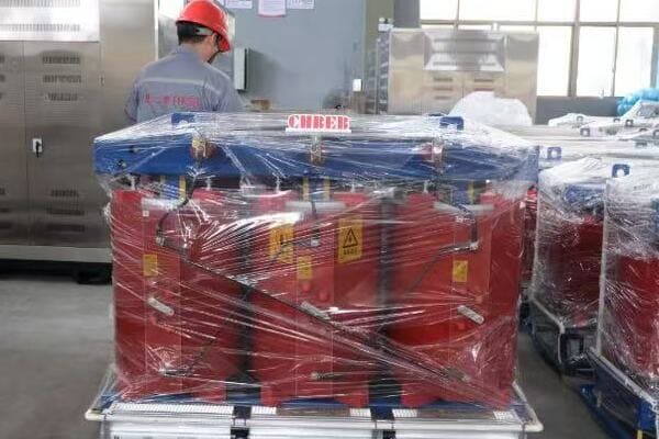
Key Types of Fuses and Their Uses
Let’s explore the main categories of fuses and their typical applications:
- Glass Tube Fuses
- Blade Fuses
- Cartridge Fuses
- High Voltage Fuses
- Resettable Fuses (PTC)
Glass Tube Fuses
Common in household and light commercial use:
- Easily visible for quick inspection
- Typically rated for lower currents (0.1A to 20A)
- Used in small appliances, electronics, and lighting circuits
I remember replacing these in old radios and TVs as a young engineer. The transparent design made it easy to spot a blown fuse, which was a great feature for troubleshooting.
Blade Fuses
Widely used in automotive applications:
- Compact and color-coded for easy identification
- Current ratings from 1A to 100A
- Designed for 12V and 24V vehicle electrical systems
During a recent electric vehicle project, we extensively used blade fuses for various subsystems. Their standardized design and easy replacement made them ideal for the modular architecture of modern EVs.
Cartridge Fuses
Versatile fuses for industrial and high-power applications:
- Available in a wide range of sizes and ratings
- Can handle currents from fractions of an amp to hundreds of amps
- Used in power distribution, motor circuits, and heavy machinery
Here’s a comparison of common fuse types:
| Fuse Type | Current Range | Typical Applications | Key Features |
|---|---|---|---|
| Glass Tube | 0.1A – 20A | Home electronics, Appliances | Visible element, Easy inspection |
| Blade | 1A – 100A | Automotive, Marine | Compact, Color-coded |
| Cartridge | 0.1A – 600A+ | Industrial equipment, Power distribution | High interrupting capacity, Various sizes |
| High Voltage | 1A – 100A+ | Utility distribution, Industrial power | Designed for kV-level protection |
| Resettable | 0.1A – 9A | Circuit boards, USB ports | Self-resetting, No replacement needed |
High Voltage Fuses
Specialized fuses for utility and industrial high voltage systems:
- Designed for voltages from 1kV to hundreds of kV
- Used in power distribution networks and large industrial equipment
- Often include additional features like arc extinguishing materials
Resettable Fuses (PTC)
Polymer-based fuses that can reset after cooling:
- No need for replacement after a fault event
- Commonly used in computer USB ports and sensitive electronics
- Limited to lower current applications compared to traditional fuses
Key points about common fuse types:
- Glass tube fuses offer easy visual inspection for household applications
- Blade fuses are compact and widely used in automotive systems
- Cartridge fuses provide versatile protection for industrial applications
4.4. High voltage fuses are specialized for utility and industrial power systems - Resettable fuses offer convenience in low-current, frequent-use applications
In my experience, selecting the right type of fuse for a specific application is crucial for ensuring optimal protection and system reliability. I recall a project where a manufacturing plant was experiencing frequent downtime due to fuse blowing in their motor control circuits. Upon investigation, we found that they were using general-purpose fuses instead of time-delay fuses designed for motor circuits. Switching to the correct type of cartridge fuse dramatically reduced unplanned stoppages and improved overall productivity.
For example, in a recent solar farm project, we had to carefully select high voltage fuses for the inverter protection. These specialized fuses needed to handle both AC and DC currents and provide protection under various fault conditions unique to solar applications. The right choice was critical not only for equipment protection but also for meeting stringent safety standards required for grid connection.
As we move on to discuss how to choose the right fuse for your project, remember that understanding these common types of fuses and their applications is the first step in making informed decisions about electrical protection in any system.
How to Choose the Right Fuse for Your Project?
Are you feeling overwhelmed by the myriad of fuse options available for your electrical project? Or perhaps you’re unsure about which specifications really matter when selecting a fuse? Choosing the right fuse is crucial for ensuring the safety and reliability of your electrical system. But how do you navigate through all the technical jargon and options to find the perfect fit?
Choosing the right fuse involves considering several key factors: voltage rating, current rating, interrupting capacity, response time, and physical size. The voltage rating must match or exceed your system’s voltage. The current rating should be just above the normal operating current. Consider the potential fault current for adequate interrupting capacity. Choose between fast-acting and time-delay fuses based on load characteristics. Ensure the fuse’s physical dimensions fit your holder or block. Always consult manufacturer specifications and local electrical codes for precise selection.
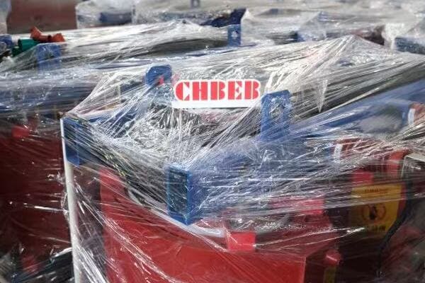
Key Factors in Fuse Selection
Let’s break down the main considerations when choosing a fuse:
- Voltage Rating
- Current Rating
- Interrupting Capacity
- Response Time
- Physical Characteristics
Voltage Rating
Matching your system’s voltage:
- Must be equal to or greater than the circuit voltage
- Consider both normal and fault conditions
- Different ratings for AC and DC applications
I once consulted on a project where fuses were consistently failing in a new installation. It turned out the fuses were rated for 250V AC, but were being used in a 480V system. This mismatch not only caused failures but posed a significant safety risk.
Current Rating
Determining the right amperage:
- Should be slightly higher than normal operating current
- Consider both steady-state and temporary overloads
- Factor in ambient temperature effects
During a recent industrial automation upgrade, we had to carefully select fuses for motor circuits. We chose fuses rated at 125% of the full load current to allow for normal operational fluctuations while still providing adequate protection.
Interrupting Capacity
Ensuring the fuse can safely interrupt fault currents:
- Must be higher than the maximum potential fault current
- Critical for preventing catastrophic failures
- Often overlooked in low-voltage applications
Here’s a quick guide for fuse selection based on application:
| Application | Voltage Rating | Current Rating | Interrupting Capacity | Response Time |
|---|---|---|---|---|
| Home Circuit | 250V | 15-20A | 10kA | Fast-acting |
| Motor Circuit | 600V | 125% of FLA | 100kA | Time-delay |
| Solar Inverter | 1000V DC | 1.5x Isc | 20kA | gPV type |
| EV Charger | 500V | 40-80A | 50kA | Fast-acting |
Response Time
Choosing between fast-acting and time-delay fuses:
- Fast-acting for sensitive electronics and short circuits
- Time-delay for motors and other high inrush current loads
- Consider normal operational characteristics of the protected equipment
Physical Characteristics
Ensuring compatibility with your system:
- Size and shape must fit the fuse holder or block
- Consider environmental factors (temperature, humidity, vibration)
- Special requirements for harsh or hazardous locations
Key points for choosing the right fuse:
- Voltage rating must match or exceed your system’s voltage
- Current rating should be just above normal operating current
- Interrupting capacity must handle potential fault currents
- Response time should suit the load characteristics
- Physical dimensions and environmental factors are crucial for proper fit and function
In my experience, proper fuse selection often requires a holistic view of the system. I recall a project where a client was experiencing nuisance fuse blowing in a critical process control system. By analyzing the load profile, we discovered brief current spikes during normal operation. Switching to properly rated time-delay fuses solved the issue, improving system reliability without compromising protection.
For example, in a recent electric vehicle charging station project, we had to select fuses that could handle both AC and DC currents, high voltages, and potential fault currents from the grid. We opted for specialized EV fuses with high interrupting capacities and fast response times to ensure user safety and equipment protection in various charging scenarios.
As we move on to discuss where to buy industrial and residential fuses, remember that choosing the right fuse is not just about meeting specifications—it’s about understanding your system’s needs and providing the right level of protection for safe and reliable operation.
Where to Buy Industrial and Residential Fuses?
Are you wondering where to source high-quality fuses for your industrial or residential project? With so many suppliers and distributors out there, how can you ensure you’re getting reliable products at competitive prices? Finding the right source for fuses is crucial for maintaining the safety and efficiency of your electrical systems.
Industrial and residential fuses can be purchased from various sources, including electrical supply distributors, online marketplaces, and directly from manufacturers. For industrial applications, reputable distributors like Grainger, Mouser Electronics, or RS Components offer a wide range of options. For residential needs, hardware stores like Home Depot or Lowe’s stock common fuse types. Online platforms such as Amazon or specialized electrical e-commerce sites provide convenient access to both industrial and residential fuses. For bulk orders or specialized fuses, contacting manufacturers directly, such as Littelfuse, Bussmann, or CHBEB, can be beneficial.
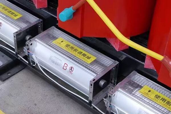
Key Sources for Purchasing Fuses
Let’s explore the main options for buying fuses:
- Electrical Supply Distributors
- Online Marketplaces
- Hardware Stores
- Direct from Manufacturers
- Specialized Electrical Retailers
Electrical Supply Distributors
Ideal for industrial and commercial needs:
- Wide range of products from multiple manufacturers
- Technical support and product selection assistance
- Often offer bulk pricing and account management
I’ve had great experiences working with distributors like Grainger and Mouser Electronics. Their technical support teams have been invaluable in helping select the right fuses for complex industrial applications.
Online Marketplaces
Convenient for both industrial and residential purchases:
- Platforms like Amazon, eBay, and AliExpress
- Wide variety of options and competitive pricing
- User reviews can be helpful for product evaluation
During a recent home renovation project, I found Amazon to be a great source for residential fuses. The ability to quickly compare different brands and read user reviews was particularly helpful.
Hardware Stores
Convenient for common residential fuses:
- Stores like Home Depot, Lowe’s, and local hardware shops
- Good for emergency replacements and small projects
- Limited selection compared to specialized suppliers
Here’s a comparison of different purchasing sources:
| Source | Best For | Advantages | Considerations |
|---|---|---|---|
| Electrical Distributors | Industrial, Bulk Orders | Wide selection, Technical support | May require account setup |
| Online Marketplaces | Variety, Convenience | Competitive pricing, User reviews | Verify seller reliability |
| Hardware Stores | Residential, Quick Needs | Immediate availability | Limited selection |
| Manufacturers | Specialized, Large Projects | Direct support, Custom options | Minimum order quantities |
| Specialized Retailers | Specific Brands/Types | Expert knowledge | May have higher prices |
Direct from Manufacturers
Ideal for large projects or specialized needs:
- Companies like Littelfuse, Bussmann, or CHBEB
- Access to full product lines and custom solutions
- Often provide detailed technical support
Specialized Electrical Retailers
Focused on electrical components:
- Online retailers like Fuse Depot or Fuse Superstore
- Extensive selection of fuse types and brands
- Often provide specialized knowledge and support
Key points about purchasing fuses:
- Electrical distributors offer wide selections and support for industrial needs
- Online marketplaces provide convenience and competitive pricing
- Hardware stores are good for common residential fuses
- Manufacturers offer direct support and custom solutions
- Specialized retailers provide focused selections and expertise
In my experience, the choice of where to buy fuses often depends on the specific needs of the project. For large industrial installations, I typically work with established electrical distributors. Their product knowledge and ability to handle large orders make them invaluable partners. However, for unique or hard-to-find fuses, I’ve found that going directly to manufacturers can be the best approach.
For example, in a recent project involving a custom-built industrial control system, we needed fuses with very specific characteristics that weren’t readily available from standard distributors. By working directly with a manufacturer, we were able to get fuses tailored to our exact specifications, ensuring optimal protection for the specialized equipment.
As we conclude our discussion on fuses, remember that choosing the right supplier is as important as selecting the correct fuse. The best source will depend on your specific needs, project scale, and required level of technical support.
FAQs: Fuse Basics and Selection Tips
To address some common questions about fuses and their selection:
-
What is the main function of a fuse?
The main function of a fuse is to protect electrical circuits and equipment from damage caused by overcurrent conditions. It acts as a sacrificial device that breaks the circuit when the current exceeds a safe level, preventing potential fires or equipment damage. -
How does a fuse protect an electrical circuit?
A fuse protects an electrical circuit by melting when too much current flows through it. The fuse contains a metal wire or strip that is designed to melt at a specific current level. When this happens, it creates an open circuit, stopping the flow of electricity and protecting the rest of the circuit from damage. -
What type of fuse do I need for home appliances?
For most home appliances, you’ll typically need glass tube fuses or ceramic fuses. The exact type and rating depend on the specific appliance. Common ratings for household fuses range from 3 to 20 amps and 125 to 250 volts. Always check your appliance’s manual or existing fuse for the correct specifications. -
Can a fuse be reused?
No, a fuse cannot be reused once it has "blown" or melted. The fusible link inside is designed to melt and break the circuit, and this process is irreversible. Always replace a blown fuse with a new one of the same type and rating. -
How do I know if a fuse is blown?
For glass fuses, you can often see a break in the metal strip inside or discoloration of the glass. For other types, you can use a multimeter to check for continuity. If there’s no continuity across the fuse, it’s blown. Some automotive fuses have a visible metal strip that breaks when the fuse blows.
Conclusion
Fuses are critical components in electrical systems, providing essential protection against overcurrent conditions. Understanding their function, types, and selection criteria is crucial for ensuring the safety and reliability of electrical equipment. Whether you’re working on a home project or industrial installation, choosing the right fuse and sourcing it from a reputable supplier are key steps in maintaining electrical safety and system integrity.
