Have you ever wondered about those green boxes in your neighborhood? They’re more important than you might think!
Pad mount transformers are essential devices that convert high-voltage electricity from power lines to a lower, usable voltage for homes and businesses. They work through electromagnetic induction, safely stepping down voltage while maintaining the same amount of power.
As an electrical engineer with years of experience in power distribution, I’ve seen firsthand how these unassuming boxes keep our lights on and our appliances running. Let’s dive into the fascinating world of pad mount transformers and uncover the secrets behind local power distribution.
What Is a Pad Mount Transformer: The Green Box in Your Neighborhood?
Ever walked past a green metal box and wondered what it’s doing there? You’re not alone in your curiosity!
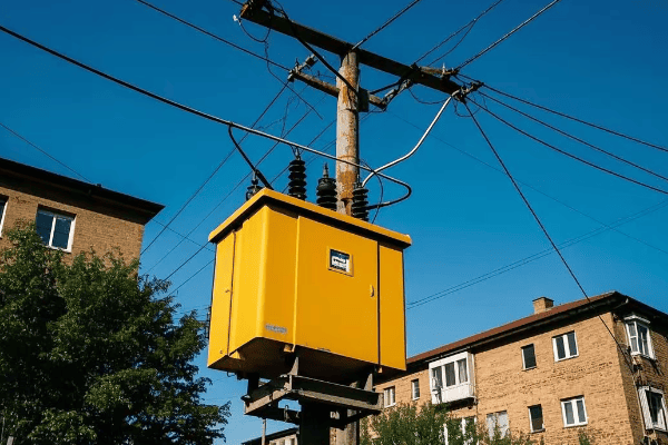
A pad mount transformer is a ground-level electrical transformer enclosed in a protective metal cabinet. It’s designed to convert high voltage electricity from utility lines to lower voltages suitable for use in homes and businesses.

I remember the first time I opened one of these transformers. The complexity inside that simple-looking box amazed me. Let’s break down what makes these devices so special:
Key Features of Pad Mount Transformers
-
Location: These transformers are installed at ground level, typically on a concrete pad. This makes them easy to access for maintenance and repairs.
-
Enclosure: The metal cabinet protects the internal components from weather and tampering. It’s usually green to blend in with the surroundings.
-
Size: They come in various sizes, depending on the power needs of the area they serve. A typical residential unit might be about the size of a large refrigerator.
-
Voltage Transformation: Inside, they contain the equipment necessary to step down high voltage (usually 7,200 to 14,400 volts) to usable levels (120/240 volts for homes).
-
Safety Features: These include locks, warning signs, and internal components designed to minimize risks.
| Feature | Description | Benefit |
|---|---|---|
| Ground-Level Installation | Mounted on concrete pads | Easy maintenance access |
| Protective Enclosure | Sealed metal cabinet | Weather and tamper resistance |
| Voltage Conversion | Steps down high to low voltage | Provides usable power for consumers |
| Safety Design | Locked, labeled, and insulated | Protects public from electrical hazards |
In my career, I’ve installed and maintained hundreds of these transformers. One project that stands out was in a new suburban development. We had to carefully plan the placement of each transformer to ensure adequate power distribution while maintaining the aesthetic appeal of the neighborhood. It was like solving a puzzle, balancing technical requirements with community needs.
Types of Pad Mount Transformers
-
Single-Phase Transformers: These are commonly used in residential areas. They typically serve 5-8 homes and are the smallest type you’ll see.
-
Three-Phase Transformers: These larger units are used for commercial areas or large residential complexes. They can handle higher power demands.
-
Loop-Feed Transformers: These have connections on both sides, allowing power to flow in either direction. They’re great for areas that need extra reliability.
-
Radial-Feed Transformers: These are simpler, with power flowing in only one direction. They’re often used in areas with straightforward power distribution needs.
Understanding the basics of pad mount transformers helps us appreciate the infrastructure that powers our daily lives. These devices are a testament to modern engineering, quietly performing their vital function day and night. Next time you pass one of these green boxes, you’ll know you’re looking at a key player in bringing electricity from the power plant to your home.
The Basics of Electricity: Understanding Voltage and Current?
Confused by electrical terms? Don’t worry, you’re not alone. Let’s break it down in simple terms.
Voltage is the pressure that pushes electricity through wires, while current is the flow of electricity itself. Think of voltage as water pressure and current as the amount of water flowing through a pipe.
I remember struggling with these concepts when I first started studying electrical engineering. Now, let me share a simple way to understand them:
Voltage: The Electrical Pressure
Voltage is measured in volts (V). It’s the force that drives electricity through a circuit. Here’s how to think about it:
- High Voltage: Like high water pressure, it can push electricity over long distances.
- Low Voltage: Similar to low water pressure, it’s safer for home use but can’t travel far.
Current: The Flow of Electricity
Current is measured in amperes (A) or amps. It represents the amount of electricity flowing through a wire. Think of it this way:
- High Current: Like a lot of water flowing through a pipe, it can do more work but needs thicker wires.
- Low Current: Like a trickle of water, it’s sufficient for small tasks and can use thinner wires.
| Concept | Electrical Term | Water Analogy | Unit of Measurement |
|---|---|---|---|
| Voltage | Electrical Pressure | Water Pressure | Volts (V) |
| Current | Electrical Flow | Water Flow | Amperes (A) |
Understanding these basics is crucial for grasping how pad mount transformers work. In my early days as an engineer, I used to explain these concepts to apprentices using a simple water system model. It always helped them visualize the invisible flow of electricity.
Power: The Combination of Voltage and Current
Power, measured in watts (W), is the product of voltage and current. It represents the rate at which electrical energy is transferred. Here’s a simple formula:
Power (W) = Voltage (V) × Current (A)
This relationship is key to understanding why we use high voltage for power transmission and lower voltage for home use:
- High Voltage Transmission: Allows for efficient long-distance power transfer with less energy loss.
- Low Voltage Distribution: Safer for end-users but requires more current to deliver the same power.
Practical Applications
Let’s look at some everyday examples:
- Home Outlet: Typically 120V in the US, capable of delivering about 15-20A of current.
- Electric Car Charger: Often uses 240V to charge batteries faster.
- Power Lines: Can carry voltages from thousands to hundreds of thousands of volts.
Understanding these basics helps explain why we need transformers. They allow us to change voltage levels to suit different needs while maintaining the same power. For instance, a pad mount transformer might take in 7,200V and output 240V, increasing the current proportionally to keep the power constant.
In my career, I’ve found that a solid grasp of these fundamentals is essential for anyone working with electrical systems. Whether you’re designing a new power distribution network or just trying to understand your home’s electrical system, these concepts form the foundation of electrical knowledge.
Inside the Box: Key Components of a Pad Mount Transformer?
Ever wondered what’s hidden behind that green metal door? Let’s take a peek inside and demystify the components.
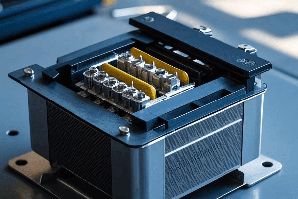
A pad mount transformer contains several key parts: the core, primary and secondary windings, insulating oil, bushings, and protective devices. Each component plays a crucial role in converting high voltage electricity to usable levels for homes and businesses.
In my years of working with these transformers, I’ve come to appreciate the intricate design of each part. Let’s break down the main components:
Core Components of a Pad Mount Transformer
-
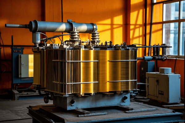
Core
- Made of thin sheets of silicon steel
- Forms a magnetic path for the transformer’s operation
- Shapes can be "core type" or "shell type"
-
Windings
- Primary Winding: Receives high voltage input
- Secondary Winding: Delivers lower voltage output
- Usually made of copper or aluminum wire
-
Insulating Oil
- Fills the transformer tank
- Serves as both an insulator and coolant
- Helps prevent arcing between components
-
Bushings
- Insulated passages for electrical connections
- Allow wires to enter and exit the transformer safely
-
Tank
- Houses all internal components
- Made of steel with a protective coating
- Often includes cooling fins or radiators
| Component | Function | Material |
|---|---|---|
| Core | Magnetic circuit | Silicon steel |
| Windings | Voltage transformation | Copper or aluminum |
| Insulating Oil | Insulation and cooling | Mineral oil or synthetic alternatives |
| Bushings | Electrical connections | Porcelain or polymer |
| Tank | Housing and protection | Steel |
I remember a project where we had to replace the core of a transformer due to damage from a power surge. The precision required in reassembling the core layers was incredible – it’s truly an art as much as a science.
How These Components Work Together
-
Electromagnetic Induction
- When AC current flows through the primary winding, it creates a changing magnetic field in the core.
- This changing field induces a voltage in the secondary winding.
-
Voltage Transformation
- The ratio of turns in the primary and secondary windings determines the voltage change.
- For example, if the primary has 100 turns and the secondary has 10, the voltage will be stepped down by a factor of 10.
-
Cooling Process
- As current flows, heat is generated in the windings.
- The insulating oil absorbs this heat and carries it to the tank walls.
- Cooling fins or radiators on the tank dissipate the heat into the air.
Additional Components for Safety and Efficiency
-
Tap Changer
- Allows for small adjustments in the turns ratio
- Helps maintain consistent output voltage despite fluctuations in input
-
Pressure Relief Device
- Releases pressure if gas builds up inside the tank
- Prevents explosion in case of severe internal faults
-
Temperature Gauge
- Monitors the oil temperature
- Helps detect overloading or cooling problems
-
Protective Relays
- Monitor various parameters like current and temperature
- Can trigger a shutdown if abnormal conditions are detected
In my experience, understanding these components is crucial for anyone working with or around pad mount transformers. Each part plays a vital role in the safe and efficient distribution of electricity to our homes and businesses. The next time you see one of these green boxes, you’ll know that inside is a marvel of engineering, working tirelessly to power our daily lives.
Step-Down Transformation: How High Voltage Becomes Usable Power?
Ever wondered how the massive voltage from power lines becomes the safe 120 volts in your home? Let’s unravel this mystery!
Step-down transformation in pad mount transformers reduces high voltage electricity to lower, safer levels for consumer use. This process uses electromagnetic induction, where the ratio of turns in the primary and secondary windings determines the voltage reduction.
I remember the first time I explained this concept to a group of new technicians. Their amazement at the simplicity and elegance of the process mirrored my own when I first learned about it. Let’s break it down:
The Basics of Step-Down Transformation
- Input Voltage: High voltage electricity enters the transformer (typically 7,200 to 14,400 volts).
- Primary Winding: This coil has many turns of wire.
- Magnetic Core: Concentrates the magnetic field created by the primary winding.
- Secondary Winding: This coil has fewer turns than the primary.
- Output Voltage: Lower voltage electricity exits the transformer (usually 120/240 volts for homes).
| Stage | Voltage Level | Purpose |
|---|---|---|
| Input | 7,200 – 14,400V | Efficient long-distance transmission |
| Primary Winding | 7,200 – 14,400V | Creates magnetic field |
| Secondary Winding | 120/240V | Induces lower voltage |
| Output | 120/240V | Safe for home use |
The key to understanding this process is the turns ratio. Here’s a simple formula:
(Primary Voltage / Secondary Voltage) = (Primary Turns / Secondary Turns)
For example, if we have 7,200V input and want 240V output, the turns ratio would be 30:1. This means for every 30 turns in the primary winding, there’s 1 turn in the secondary.
The Physics Behind the Magic
- Electromagnetic Induction: When alternating current flows through the primary winding, it creates a changing magnetic field.
- Magnetic Core: This field is concentrated and directed by the iron core.
- Induced Voltage: The changing magnetic field induces a voltage in the secondary winding.
- Voltage Reduction: Fewer turns in the secondary winding result in lower induced voltage.
I once had to explain this to a city council when we were upgrading a neighborhood’s power distribution. Using a simple demonstration with two coils and a battery, I showed how changing the number of turns in the secondary coil affected the output voltage. It was a lightbulb moment for many of them!
Practical Implications
Understanding step-down transformation helps explain several aspects of our power system:
- Efficiency: High voltage transmission is more efficient over long distances.
- Safety: Lower voltage is safer for end-users.
- Flexibility: Different secondary windings can provide various voltage levels (e.g., 120V and 240V) from the same transformer.
Challenges in Step-Down Transformation
- Heat Generation: The process isn’t 100% efficient, and some energy is lost as heat.
- Voltage Regulation: Maintaining consistent output voltage under varying loads can be challenging.
- Harmonics: Non-linear loads can create harmonic distortions, affecting power quality.
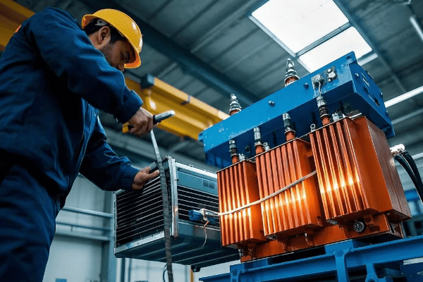
In my years working with transformers, I’ve seen how crucial proper design and maintenance are to ensuring efficient step-down transformation. Regular oil testing, thermal imaging, and load monitoring all play a part in keeping these devices operating at peak efficiency.
Understanding step-down transformation is key to appreciating the complex yet elegant system that brings power to our homes. It’s a perfect example of how fundamental principles of physics are applied to solve real-world challenges in power distribution.
Safety First: Protection Features in Pad Mount Transformers?
Worried about the safety of those green boxes in your neighborhood? You’ll be relieved to know they’re designed with multiple layers of protection.
Pad mount transformers incorporate several safety features, including tamper-resistant enclosures, internal fuses, lightning arresters, and automatic shut-off mechanisms. These features work together to protect both the public and utility workers from electrical hazards.
In my years of working with these transformers, I’ve seen how crucial these safety features are. Let me walk you through the key protections:
Key Safety Features
-
Tamper-Resistant Enclosure
- Locked metal cabinet
- Requires special tools to open
- Deters unauthorized access
-
Internal Fuses
- Protect against overcurrent
- Automatically disconnect in case of faults
-
Lightning Arresters
- Divert lightning strikes to ground
- Protect internal components from voltage surges
-
Automatic Pressure Relief Valve
- Releases pressure in case of internal faults
- Prevents explosive rupture of the tank
-
Thermal Protection
- Monitors oil temperature
- Can trigger shutdown if overheating occurs
| Safety Feature | Function | Benefit |
|---|---|---|
| Tamper-Resistant Enclosure | Prevents unauthorized access | Public safety |
| Internal Fuses | Protect against overcurrent | Equipment protection |
| Lightning Arresters | Guard against voltage surges | Reliability |
| Pressure Relief Valve | Prevents explosion | Catastrophic failure prevention |
| Thermal Protection | Monitors temperature | Overheating prevention |
I remember a incident where a car crashed into a pad mount transformer in a residential area. Thanks to the robust enclosure and internal safety features, there was no electrical fire or shock risk to bystanders. It really drove home the importance of these safety measures.
Additional Safety Measures
-
Grounding
- All metal parts are grounded
- Prevents electric shock in case of insulation failure
-
Oil Containment
- Designed to prevent
-
Oil Containment
- Designed to prevent oil leaks
- Protects the environment in case of internal failures
-
Warning Labels
- Clear signage indicating high voltage danger
- Instructions for emergency situations
-
Dead-Front Design
- No exposed live parts when opened for maintenance
- Reduces risk of accidental contact with high voltage components
In my career, I’ve conducted numerous safety training sessions for utility workers. One exercise I always include is a "spot the hazard" game using photos of various transformer installations. It’s amazing how this simple activity sharpens awareness and potentially saves lives.
Safety Protocols for Utility Workers
While pad mount transformers are designed for safety, utility workers still follow strict protocols:
-
Personal Protective Equipment (PPE)
- Insulated gloves and boots
- Arc-flash protective clothing
-
Lock-Out/Tag-Out Procedures
- Ensure power is off before maintenance
- Prevent accidental re-energizing
-
Regular Training
- Workers are trained on latest safety procedures
- Includes emergency response drills
Public Safety Education
As part of my role, I often participate in community outreach programs to educate the public about transformer safety. Here are some key points we emphasize:
- Never touch or attempt to open a pad mount transformer
- Keep the area around transformers clear of debris and vegetation
- Report any signs of damage or tampering to your local utility company
- In case of fire or unusual noises, stay away and call emergency services
Continuous Improvement in Safety Design
The field of transformer safety is always evolving. Some recent innovations include:
-
Smart Monitoring Systems
- Real-time monitoring of transformer health
- Early detection of potential issues
-
Eco-Friendly Insulating Fluids
- Less flammable than traditional mineral oil
- Reduced environmental impact in case of leaks
-
Enhanced Seismic Protection
- Designs that better withstand earthquakes
- Crucial in geologically active areas
Understanding these safety features helps build public confidence in our power distribution system. Pad mount transformers are designed with multiple layers of protection to ensure the safety of both the public and utility workers. As technology advances, we continue to see improvements in safety features, making these essential components of our power grid even more secure and reliable.
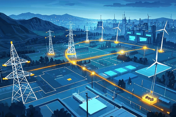
From Power Plant to Your Home: The Journey of Electricity?
Ever flipped a switch and wondered how that electricity got to your home? It’s a fascinating journey that starts miles away!
Electricity travels from power plants through a complex network of transmission lines, substations, and transformers before reaching your home. Pad mount transformers play a crucial role in the final step, converting high voltage to safe, usable levels for household consumption.

As someone who’s worked at various stages of this journey, I find the entire process remarkable. Let’s break down the steps:
The Electricity Journey: From Generation to Consumption
-
Power Generation
- Electricity is generated at power plants (coal, nuclear, hydroelectric, solar, wind)
- Typical generation voltage: 2,300 to 30,000 volts
-
Step-Up Transformation
- Large transformers at the plant increase voltage for long-distance transmission
- Transmission voltage: 115,000 to 765,000 volts
-
Transmission
- High voltage electricity travels long distances on transmission lines
- These are the tall towers you see crossing the countryside
-
Substation Step-Down
- Substations use transformers to reduce voltage for local distribution
- Distribution voltage: typically 7,200 to 14,400 volts
-
Local Distribution
- Electricity travels on smaller poles or underground lines through neighborhoods
-
Pad Mount Transformer
- Converts distribution voltage to household voltage (120/240 volts)
- The final step before electricity enters your home
| Stage | Voltage Level | Purpose |
|---|---|---|
| Generation | 2,300 – 30,000V | Initial power creation |
| Transmission | 115,000 – 765,000V | Efficient long-distance travel |
| Distribution | 7,200 – 14,400V | Local area supply |
| Household | 120/240V | Safe for home use |
I remember a field trip I organized for engineering students to follow this journey. We started at a hydroelectric dam, followed the transmission lines to a substation, and ended at a residential pad mount transformer. Seeing the scale of the system firsthand was eye-opening for many of them.
Why Multiple Voltage Changes?
You might wonder why we change voltage so many times. Here’s why:
- Efficiency: High voltage is more efficient for long-distance transmission. It reduces energy loss.
- Safety: Lower voltage is safer for end-users.
- Practicality: Different voltages suit different purposes (e.g., industrial vs. residential use).
Challenges Along the Journey
- Energy Loss: Some energy is lost as heat at each transformation stage.
- Maintenance: The entire system requires constant monitoring and maintenance.
- Weather Impact: Storms can damage transmission lines and cause outages.
- Balancing Load: The grid must constantly balance supply with demand.
The Role of Pad Mount Transformers
Pad mount transformers are the unsung heroes of this journey. They perform the crucial final step:
- Voltage Conversion: They take the 7,200-14,400V from distribution lines and convert it to 120/240V for homes.
- Safety: They provide a safe interface between the distribution system and residential areas.
- Load Management: They’re sized to handle the electrical needs of multiple homes or businesses.
In my career, I’ve seen the impact of well-designed local distribution systems. A properly placed and maintained pad mount transformer can mean the difference between reliable power and frequent outages for an entire neighborhood.
The Future of Electricity Distribution
The journey of electricity is evolving with new technologies:
- Smart Grids: Incorporating digital technology for better monitoring and control.
- Renewable Integration: Adapting the grid to handle distributed generation from solar and wind.
- Energy Storage: Incorporating batteries to balance load and improve reliability.
Understanding this journey helps us appreciate the complex system that brings power to our homes. From massive power plants to the humble pad mount transformer on your street, each component plays a vital role in keeping our lights on and our devices running.
Conclusion
Pad mount transformers are crucial links in our power distribution chain, safely bringing electricity from high-voltage lines to our homes. Understanding their function helps us appreciate the complex system powering our daily lives and the importance of ongoing maintenance and innovation in electrical infrastructure.
🚀Next steps, you can:
A. Learn more about energy efficiency in your home
B. Explore careers in electrical engineering and power systems
C. Understand how to report transformer issues in your area
D. Discover the role of transformers in renewable energy integration
E. Investigate smart grid technologies and their impact on power distribution
F. Find out about community initiatives for grid modernization
