Are you confused about the differences between power transformers and distribution transformers? You’re not alone. Many engineers struggle to understand their unique roles in electrical systems.
Power transformers and distribution transformers are crucial components in electrical systems. Power transformers handle high voltages and large capacities in transmission systems. Distribution transformers step down voltage for end-user distribution. Understanding their differences is essential for proper system design and operation.
In this article, I’ll break down the key differences between power and distribution transformers. We’ll explore their basic functions, size, voltage levels, design, efficiency, cooling systems, protection, and applications. Whether you’re designing a new system or maintaining an existing one, this knowledge is crucial for any electrical engineer.
What Are Power Transformers and Distribution Transformers: Basic Definitions and Functions?
Have you ever wondered why we need different types of transformers in our power systems? The answer lies in the unique roles of power transformers and distribution transformers. But what exactly are they, and what do they do?
Power transformers are large, high-capacity transformers used in transmission systems to step up or step down high voltages. Distribution transformers are smaller units used to lower voltage levels for final distribution to end-users. Both types are essential for efficient power transmission and distribution.
Let’s dive deeper into the basic definitions and functions of power and distribution transformers. Understanding these fundamentals is crucial for grasping their roles in our electrical systems.
Power Transformers
-
Definition
- Large, high-capacity transformers
- Typically rated above 69 kV
-
Primary Functions
- Step up voltage for long-distance transmission
- Step down voltage at substations for sub-transmission or distribution
-
Key Characteristics
- High power ratings (often >10 MVA)
- Designed for high efficiency
- Often include advanced cooling and monitoring systems
Distribution Transformers
-
Definition
- Smaller transformers used in distribution networks
- Typically rated below 35 kV
-
Primary Functions
- Step down voltage for final distribution to end-users
- Provide isolation between primary and secondary systems
-
Key Characteristics
- Lower power ratings (typically <5 MVA)
- Designed for reliability and long life
- Often use simpler cooling methods
| Aspect | Power Transformer | Distribution Transformer |
|---|---|---|
| Voltage Level | High (>69 kV) | Lower (<35 kV) |
| Capacity | Large (>10 MVA) | Smaller (<5 MVA) |
| Primary Use | Transmission Systems | End-User Distribution |
| Design Focus | High Efficiency | Reliability and Cost-Effectiveness |
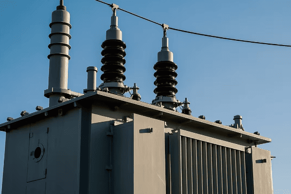
The distinction between power transformers and distribution transformers became clear to me early in my career. I remember visiting a large substation where I saw a massive power transformer for the first time. Its size was impressive – easily as large as a small house. The engineer explaining its function told me it was stepping down voltage from 500 kV to 138 kV for sub-transmission. That’s when I really understood the scale at which power transformers operate.
Power transformers are the workhorses of our transmission systems. They handle enormous amounts of power at very high voltages. Their primary function is to either step up voltage at power plants for long-distance transmission or step it down at substations for sub-transmission or distribution. The high voltages they deal with, typically above 69 kV, allow for efficient long-distance power transmission by reducing current and, consequently, power losses.
One key characteristic of power transformers is their high power rating, often above 10 MVA. This high capacity is necessary to handle the large amounts of power flowing through transmission systems. I once worked on a project involving a 500 MVA power transformer. The sheer amount of energy it could handle was mind-boggling – enough to power a small city!
Efficiency is a crucial consideration in power transformer design. Even a small improvement in efficiency can lead to significant energy savings given the large amounts of power these transformers handle. I’ve been involved in projects where we’ve used advanced core materials like amorphous metals to reduce no-load losses in power transformers. The energy savings over the transformer’s lifetime easily justified the higher initial cost.
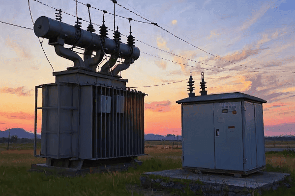
On the other hand, distribution transformers play a different but equally important role. I first encountered these in a more familiar setting – the green boxes you might see in residential areas or the cylindrical units on power poles. These transformers are the final step in bringing power to our homes and businesses.
Distribution transformers typically operate at lower voltages, usually below 35 kV on the primary side, stepping down to the final utilization voltage (like 120/240V for residential use in North America). Their capacity is generally lower than power transformers, typically below 5 MVA. I’ve worked on many projects involving distribution transformers, and what always strikes me is their ubiquity. You can find them in every neighborhood, quietly performing their essential function.
While efficiency is still important for distribution transformers, the design focus often shifts more towards reliability and cost-effectiveness. These transformers need to operate for decades with minimal maintenance. I remember a project where we were replacing distribution transformers in an old urban area. Some of the units we removed had been in service for over 50 years!
One interesting aspect of distribution transformers is their role in providing isolation between the primary and secondary systems. This isolation is crucial for safety and power quality. I once worked on a troubleshooting project where a failed distribution transformer had led to high voltage appearing on the low voltage side. It really drove home the importance of this isolation function.
Understanding the basic definitions and functions of power and distribution transformers is crucial for anyone working in electrical engineering. Whether you’re designing a new power system, troubleshooting issues, or simply trying to understand how electricity gets from power plants to your home, knowing the roles of these different types of transformers is essential. As we continue to evolve our power systems, with more distributed generation and smart grid technologies, the functions of these transformers may evolve, but their fundamental roles in power transmission and distribution will remain crucial.
Size and Capacity: How Power Transformers and Distribution Transformers Differ?
Have you ever wondered why some transformers are as big as houses while others fit on a utility pole? The size and capacity differences between power transformers and distribution transformers are striking, but what’s behind these differences?
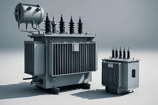
Power transformers are significantly larger and have higher capacities than distribution transformers. Power transformers can be as large as a house, with capacities often exceeding 100 MVA. Distribution transformers are much smaller, typically under 5 MVA, designed for pole mounting or pad installation in local areas.
Let’s explore the size and capacity differences between power and distribution transformers in more detail. Understanding these differences is crucial for proper transformer selection and system design.
Power Transformers
-
Size
- Can be as large as a small house
- Often require special transportation arrangements
-
Capacity
- Typically range from 10 MVA to over 1000 MVA
- Some of the largest units exceed 1500 MVA
-
Weight
- Can weigh hundreds of tons
- Requires specialized foundations
Distribution Transformers
-
Size
- Much smaller, can be pole-mounted or pad-mounted
- Typically range from a few cubic feet to a small room size
-
Capacity
- Usually range from 5 kVA to 5000 kVA (5 MVA)
- Most common sizes in residential areas are 25-100 kVA
-
Weight
- Can range from a few hundred pounds to several tons
- Larger units may require special handling but not to the extent of power transformers
| Aspect | Power Transformer | Distribution Transformer |
|---|---|---|
| Typical Size | House-sized | Pole-mounted to small room |
| Capacity Range | 10 MVA – 1000+ MVA | 5 kVA – 5000 kVA |
| Weight | Hundreds of tons | Hundreds to thousands of pounds |
| Installation | Requires specialized site | Pole, pad, or vault mounted |
The size and capacity differences between power transformers and distribution transformers are truly remarkable. I’ve had the opportunity to work with both types throughout my career, and the contrast never ceases to amaze me.
I remember my first encounter with a large power transformer during a substation construction project. The transformer was being delivered, and it was a sight to behold. It was transported on a specialized multi-axle trailer, escorted by several vehicles. The transformer itself was as large as a small house, dwarfing everything around it. This particular unit was rated at 500 MVA and weighed over 400 tons. The logistics of moving and installing such a massive piece of equipment were incredibly complex.
Power transformers of this size are typically used in major substations or at large power generation facilities. Their enormous capacity allows them to handle the vast amounts of power flowing through transmission systems. I’ve worked on projects with even larger units, some exceeding 1000 MVA. These transformers play a crucial role in our power systems, enabling the efficient transmission of electricity over long distances.
The size of power transformers is directly related to their capacity and voltage rating. Higher capacity and voltage generally require larger core and winding assemblies, more insulation, and more substantial cooling systems. I once visited a transformer manufacturing facility where they were building a 765 kV transformer. The size of the bushings alone was impressive – taller than a person!
The weight of these large power transformers presents significant challenges. They require specialized foundations capable of supporting hundreds of tons. I’ve been involved in projects where we had to design reinforced concrete foundations with extensive piling systems to support these massive transformers. The foundation design is crucial not just for supporting the weight, but also for managing potential oil spills and providing stability during seismic events.
In stark contrast, distribution transformers are much more modest in size and capacity. I’ve worked extensively with these transformers in urban and rural electrification projects. The size difference compared to power transformers is striking. Many distribution transformers are small enough to be mounted on a single utility pole.
The capacity of distribution transformers typically ranges from 5 kVA to 5000 kVA (5 MVA). In residential areas, I most commonly work with transformers in the 25-100 kVA range. These are the transformers you might see on poles or in small green boxes in your neighborhood. Despite their smaller size, they play a crucial role in the final step of power delivery to homes and businesses.
I remember a project in a dense urban area where we were upgrading the distribution system. We used pad-mounted transformers rated at 2500 kVA. While these were larger than typical pole-mounted units, they were still tiny compared to power transformers. We were able to install them in small, fenced-off areas on the street, something that would be impossible with a power transformer.
The weight of distribution transformers, while much less than power transformers, can still be significant. Larger pad-mounted units can weigh several tons. I’ve been involved in projects where we had to carefully plan the installation process, using cranes or specialized lifting equipment. However, many smaller distribution transformers can be installed using standard utility trucks, which is a far cry from the specialized equipment needed for power transformers.
The size and capacity differences between power and distribution transformers reflect their different roles in the power system. Power transformers need to handle enormous amounts of power at high voltages, hence their large size and high capacity. Distribution transformers, on the other hand, are designed to be widely distributed throughout communities, necessitating a smaller, more manageable size.
Understanding these size and capacity differences is crucial for system planning and design. When I’m working on a new substation project or a distribution system upgrade, carefully considering the size and capacity requirements of the transformers is one of the first steps. It affects everything from site selection and preparation to transportation logistics and installation methods.
As we continue to evolve our power systems, with more distributed generation and smart grid technologies, the size and capacity requirements for transformers may change. I’m seeing interesting developments in modular and scalable transformer designs that could bridge the gap between traditional power and distribution transformer categories. However, for now, the stark contrast in size and capacity between these two types of transformers remains a fundamental characteristic of our power systems.
Voltage Levels: Comparing the Operating Ranges of Power and Distribution Transformers?
Have you ever wondered why we need different transformer types for various parts of the power system? The answer largely lies in the vastly different voltage levels they handle. But what exactly are these voltage ranges, and why are they important?
Power transformers typically operate at high voltage levels, often above 69 kV, with some units handling up to 765 kV or more. Distribution transformers work at lower voltages, usually below 35 kV on the primary side, stepping down to utilization voltages like 120/240V for end-users. These voltage ranges reflect their roles in power transmission and distribution.
Let’s delve deeper into the operating voltage ranges of power and distribution transformers. Understanding these differences is crucial for system design and transformer selection.
Power Transformer Voltage Levels
-
Primary Voltage
- Typically ranges from 69 kV to 765 kV
- Some ultra-high voltage systems go up to 1000 kV or more
-
Secondary Voltage
- Often in the range of 69 kV to 345 kV
- Depends on the specific application and system design
-
Voltage Ratio
- Can step up or step down voltage
- Ratios can be quite large, sometimes 10:1 or more
Distribution Transformer Voltage Levels
-
Primary Voltage
- Usually ranges from 4 kV to 35 kV
- Common primary voltages include 12.47 kV, 25 kV, 34.5 kV
-
Secondary Voltage
- Typically 120/240V for residential single-phase
- 208Y/120V or 480Y/277V for three-phase commercial/industrial
-
Voltage Ratio
- Always steps down voltage
- Ratios are typically smaller than power transformers, often around 20:1 to 40:1
| Aspect | Power Transformer | Distribution Transformer |
|---|---|---|
| Primary Voltage | 69 kV – 765 kV+ | 4 kV – 35 kV |
| Secondary Voltage | 69 kV – 345 kV | 120V – 480V |
| Typical Voltage Ratio | Can be 10:1 or more | Usually 20:1 to 40:1 |
| Direction of Transformation | Can step up or down | Always steps down |
The voltage levels at which power and distribution transformers operate are vastly different, reflecting their distinct roles in the electrical system. Throughout my career, I’ve worked with transformers across this entire voltage spectrum, and the differences are not just in the numbers – they impact every aspect of transformer design and application.
Let’s start with power transformers. These units operate at the highest voltage levels in our power systems. I remember my first encounter with a 500 kV transformer at a major substation. The sheer size of the bushings and the extensive insulation required were awe-inspiring. These high voltages are crucial for long-distance power transmission, as they allow for lower currents and thus lower losses over long distances.
Power transformers can have primary voltages ranging from 69 kV up to 765 kV or even higher. I’ve been involved in projects with ultra-high voltage transformers operating at 1000 kV. These extreme voltages present significant engineering challenges in terms of insulation, cooling, and protection systems. The clearances required around these transformers are substantial – I once worked on a 765 kV substation where the minimum clearance to ground for energized parts was over 7 meters!
The secondary voltage of power transformers can vary widely depending on the application. In many cases, they’re stepping down to sub-transmission voltages, which might be in the range of 69 kV to 345 kV. However, I’ve also worked on generator step-up transformers that do the opposite, stepping up from the generator voltage (typically 15-25 kV) to transmission voltages.
The voltage ratios in power transformers can be quite large. I remember a project involving a transformer stepping down from 500 kV to 69 kV – a ratio of more than 7:1. These large ratios require careful design of the windings and insulation systems to manage the high turn ratios and potential stresses.
Distribution transformers, on the other hand, operate at much lower voltages. The primary voltages are typically what we call "distribution voltages," ranging from about 4 kV to 35 kV. In my work with utilities, I commonly encounter primary voltages like 12.47 kV, 25 kV, and 34.5 kV. These voltages are high enough for efficient local distribution but low enough to be manageable with more compact equipment.
The secondary voltages of distribution transformers are what we use in our homes and businesses. For residential single-phase service in North America, this is typically 120/240V. I’ve worked on many projects involving these familiar voltages. For commercial and industrial three-phase applications, common secondary voltages include 208Y/120V and 480Y/277V. I remember a project for a large industrial facility where we used 480V distribution to power heavy machinery, with smaller transformers stepping down to 208V or 120V for lighting and office equipment.
One key difference between power and distribution transformers is the direction of voltage transformation. Power transformers can step voltage up or down, depending on their location in the system. I’ve worked on projects where we used step-up transformers at power plants to increase voltage for transmission, and step-down transformers at substations to reduce voltage for distribution. Distribution transformers, however, always step voltage down. Their role is to take the distribution-level voltage and reduce it to the final utilization voltage for end-users.
The voltage ratio of distribution transformers is typically smaller than that of power transformers. Most distribution transformers I’ve worked with have ratios in the range of 20:1 to 40:1. For example, a transformer taking 12.47 kV down to 240V has a ratio of about 52:1. This is still a significant step-down, but not as extreme as what we see in some power transformers.
Understanding these voltage levels is crucial for system design and transformer selection. When I’m working on a new project, one of the first things I consider is the voltage levels involved. This determines not just the transformer specifications, but also impacts the design of the entire system – from the size of conductors to the type of insulators and the layout of substations.
The voltage levels also have significant implications for safety and insulation coordination. Higher voltages require larger clearances and more robust insulation systems. I remember a project where we were upgrading a substation from 138 kV to 230 kV. The increase in voltage meant we had to completely redesign the substation layout to accommodate the larger clearances required.
Interestingly, the trend towards distributed generation and microgrids is beginning to blur the lines between traditional voltage levels. I’ve worked on projects involving medium-voltage DC systems and solid-state transformers that challenge the conventional voltage level distinctions. However, for the majority of our power system, the clear separation between the high voltages of power transformers and the lower voltages of distribution transformers remains a fundamental characteristic.
Another aspect to consider is the impact of voltage levels on transformer design and construction. Power transformers operating at extra-high voltages require sophisticated insulation systems. I’ve seen power transformers with complex arrangements of oil ducts and barriers to manage the extreme electric fields. Distribution transformers, while still requiring careful insulation design, typically have simpler constructions due to their lower voltages.
Voltage regulation is another area where the different voltage levels come into play. Power transformers often include on-load tap changers to adjust the voltage ratio in response to system conditions. I’ve worked on projects where these tap changers play a crucial role in maintaining stable voltages across the transmission system. Distribution transformers, operating at lower voltages and with smaller capacity, typically use simpler off-load taps that can be adjusted when the transformer is de-energized.
The choice of voltage levels in a power system is a complex optimization problem. Higher voltages allow for more efficient long-distance transmission but require more expensive equipment. Lower voltages are easier to manage but result in higher losses for a given power level. Throughout my career, I’ve been involved in numerous studies to determine the optimal voltage levels for different parts of the power system, balancing efficiency, cost, and reliability.
As we continue to evolve our power systems, with increasing penetration of renewable energy and the development of smart grids, the traditional voltage level distinctions may evolve. However, the fundamental principle of using higher voltages for bulk power transmission and lower voltages for local distribution is likely to remain a cornerstone of our electrical systems for the foreseeable future.
Understanding the voltage levels of power and distribution transformers is essential for anyone working in electrical engineering. Whether you’re designing a new substation, planning a distribution network, or simply trying to understand how electricity gets from power plants to your home, knowing these voltage ranges and their implications is crucial. As we push towards more efficient and flexible power systems, this knowledge will continue to be fundamental to our work in shaping the future of electricity distribution.
Design and Construction: Key Differences in Core and Winding Configurations?
Have you ever wondered what’s inside a transformer and how its internal structure differs between power and distribution types? The design and construction, particularly the core and winding configurations, play a crucial role in a transformer’s performance and efficiency.
Power transformers often use more complex core and winding configurations to handle high voltages and large capacities. They frequently employ shell-type cores and disc or helical windings. Distribution transformers typically use simpler, more cost-effective designs like core-type construction and layer windings.

Let’s delve deeper into the design and construction differences between power and distribution transformers, focusing on their core and winding configurations. This knowledge is essential for understanding transformer performance and making informed decisions in system design.
Power Transformer Design
-
Core Configuration
- Often use shell-type cores for better mechanical strength
- May employ wound cores for very large units
-
Winding Configuration
- Typically use disc or helical windings
- May employ Continuously Transposed Conductors (CTC)
-
Insulation System
- Complex oil-paper insulation with multiple barriers
- May include advanced oil preservation systems
Distribution Transformer Design
-
Core Configuration
- Typically use core-type construction
- Often employ stacked core design for ease of manufacturing
-
Winding Configuration
- Usually use layer or foil windings
- Simpler designs for cost-effectiveness
-
Insulation System
- Simpler oil-paper insulation
- May use dry-type designs for indoor applications
| Aspect | Power Transformer | Distribution Transformer |
|---|---|---|
| Core Type | Often shell-type | Typically core-type |
| Winding Type | Disc or helical | Layer or foil |
| Insulation Complexity | High | Moderate to Low |
| Design Priority | Performance and efficiency | Cost-effectiveness and reliability |
The design and construction of power and distribution transformers, particularly their core and winding configurations, reflect their different roles and operating conditions. Throughout my career, I’ve had the opportunity to work with both types, and the differences in their internal structure always fascinate me.
Let’s start with power transformers. These units often employ shell-type cores, where the core surrounds the windings. I remember visiting a transformer manufacturing plant where they were assembling a large shell-type transformer. The core looked like a massive steel fortress encasing the windings. This design provides excellent mechanical strength, which is crucial for power transformers that may need to withstand severe short-circuit forces.
For very large power transformers, I’ve seen wound core designs used. These cores are formed by winding a continuous strip of core steel, which can reduce core losses. I worked on a project involving a 1000 MVA transformer with a wound core. The precision required in manufacturing such a large wound core was impressive.
The winding configuration in power transformers is often more complex than in distribution transformers. Disc windings are common, especially for high-voltage applications. These consist of a series of flat coils connected in series. I’ve also worked with transformers using helical windings, where the conductor is wound in a continuous helix. These designs allow for better control of voltage distribution and improved cooling.
One interesting development I’ve seen in power transformer windings is the use of Continuously Transposed Conductors (CTC). These are made up of multiple insulated strands that are continuously transposed along the length of the conductor. I remember a project where we specified CTCs for a large power transformer. The reduction in eddy current losses was significant, improving the overall efficiency of the transformer.
The insulation system in power transformers is often quite complex. They typically use oil-paper insulation with multiple barriers to manage the high electric fields. I’ve been involved in projects where we’ve implemented sophisticated oil preservation systems, using nitrogen blankets or rubber bags to prevent oil oxidation and extend the transformer’s life.
Moving on to distribution transformers, the design priorities shift towards cost-effectiveness and reliability for widespread deployment. These transformers typically use a core-type construction, where the windings surround the core legs. I’ve worked on many projects involving distribution transformers, and this design is almost universal due to its simplicity and effectiveness.
The core in distribution transformers is often a stacked design, built up from individual laminations. This approach is cost-effective and allows for easier manufacturing. I remember visiting a factory that was mass-producing cores for distribution transformers. The speed and efficiency of the production line were impressive, highlighting the importance of simplicity in design for these high-volume products.
Winding configurations in distribution transformers are generally simpler. Layer windings are common, where the conductor is wound in layers around a cylindrical form. For larger distribution transformers, I’ve also seen foil windings used, where thin aluminum or copper foil forms the winding. These designs are chosen for their balance of performance and manufacturability.
The insulation system in distribution transformers is typically simpler than in power transformers. While they still use oil-paper insulation, the design is less complex due to the lower voltages involved. I’ve also worked on projects using dry-type distribution transformers, particularly for indoor applications where fire safety is a concern. These use solid insulation materials instead of oil, which can be advantageous in certain situations.
One interesting trend I’ve observed is the increasing use of amorphous metal cores in distribution transformers. These materials can significantly reduce no-load losses. I was involved in a project where a utility was replacing old distribution transformers with new units using amorphous cores. The energy savings over the transformers’ lifetime easily justified the higher initial cost.
The design differences between power and distribution transformers extend to other aspects as well. Power transformers often include more sophisticated cooling systems, like forced oil and forced air cooling (OFAF), while distribution transformers typically rely on natural oil circulation and air cooling (ONAN). I’ve worked on power transformer projects where the cooling system design was almost as complex as the transformer itself.
Another area where I’ve seen significant differences is in the bushings. Power transformers, especially at higher voltages, use large, complex bushings to manage the high electric fields. I remember a project involving a 500 kV transformer where the bushings were taller than a person! Distribution transformers, operating at lower voltages, use much simpler and smaller bushings.
Understanding these design and construction differences is crucial for anyone working with transformers. Whether you’re specifying a new transformer, troubleshooting an existing unit, or designing a power system, knowing how the internal structure of transformers varies between power and distribution types is essential. As we continue to push for more efficient and reliable power systems, I expect we’ll see further innovations in transformer design, particularly in areas like advanced materials and smart monitoring systems.
Efficiency and Losses: Comparing Performance of Power and Distribution Transformers?
Have you ever wondered why some transformers are more efficient than others? Or why efficiency is such a big deal in transformer design? The efficiency and losses of transformers are critical factors that impact both operational costs and environmental footprint.
Power transformers typically have higher efficiencies, often exceeding 99%, due to their large size and the critical nature of their role. Distribution transformers usually have good efficiencies in the range of 97-99%. Both types experience no-load (core) losses and load (winding) losses, but the balance and management of these losses differ.

Let’s explore the efficiency and losses of power and distribution transformers in more detail. Understanding these aspects is crucial for optimizing energy use and making informed decisions in power system design.
Power Transformer Efficiency
-
Overall Efficiency
- Typically exceeds 99%
- Even small improvements can lead to significant energy savings
-
No-Load Losses
- Caused by core magnetization
- Managed through use of high-grade core materials
-
Load Losses
- Due to resistance in windings
- Minimized through optimal conductor design
Distribution Transformer Efficiency
-
Overall Efficiency
- Usually ranges from 97% to 99%
- Balances performance with cost-effectiveness
-
No-Load Losses
- More significant proportion of total losses compared to power transformers
- Managed through core design and material selection
-
Load Losses
- Vary with the square of the load current
- Optimized based on expected load profile
| Aspect | Power Transformer | Distribution Transformer |
|---|---|---|
| Typical Efficiency | >99% | 97-99% |
| No-Load Losses | Lower proportion of total losses | Higher proportion of total losses |
| Load Losses | Significant due to high currents | Vary widely based on loading |
| Efficiency Optimization | Focused on high-load operation | Balanced for variable loading |
Efficiency and losses are critical considerations in transformer design and operation. Throughout my career, I’ve seen how even small improvements in efficiency can lead to substantial energy savings and cost reductions over a transformer’s lifetime.
Let’s start with power transformers. These units typically have very high efficiencies, often exceeding 99%. I remember working on a project involving a large 500 MVA power transformer. We were aiming for an efficiency of 99.6%. At first, this might not sound like a big improvement over 99%, but when you’re dealing with such large amounts of power, even a fraction of a percent can represent significant energy savings.
In power transformers, managing losses is crucial due to the sheer amount of energy they handle. No-load losses, also called core losses, are present whenever the transformer is energized, regardless of the load. These are primarily due to hysteresis and eddy currents in the transformer’s core. I’ve been involved in projects where we’ve used advanced core materials like amorphous metals or high-grade grain-oriented electrical steel to minimize these losses. The cost of these materials is often justified by the energy savings over the transformer’s lifetime.
Load losses in power transformers are due to the resistance in the windings and vary with the square of the load current. Given the high currents involved in power transformers, these losses can be substantial. I’ve worked on designs using Continuously Transposed Conductors (CTC) to reduce eddy current losses in the windings. In one project, this approach allowed us to significantly reduce load losses during high-load conditions.
The efficiency of power transformers is typically optimized for high-load operation, as they often operate near their rated capacity. However, I’ve also been involved in projects where we had to consider a wide range of loading conditions, requiring a careful balance between no-load and load losses.
Moving on to distribution transformers, efficiency is still important, but there’s often more of a balance with cost-effectiveness. These transformers typically have efficiencies in the range of 97% to 99%. While this might seem lower than power transformers, it’s important to remember that distribution transformers are much smaller and handle less power.
One interesting aspect of distribution transformer efficiency is the relative importance of no-load losses. Since these transformers often operate at partial load, and many are energized 24/7 regardless of load, no-load losses can represent a significant proportion of total losses. I’ve worked on projects where utilities have implemented programs to replace old distribution transformers with new, high-efficiency units. The focus was often on reducing no-load losses, as these are constant regardless of load.
Load losses in distribution transformers, while still important, can vary widely based on the loading. I remember a project where we were specifying transformers for a residential area. We had to carefully analyze the expected load profile to determine the optimal balance between no-load and load losses. In some cases, a transformer with higher no-load losses but lower load losses was more efficient overall due to the specific load characteristics.
The efficiency standards for distribution transformers have become increasingly stringent over the years. I’ve been involved in projects where we had to redesign transformers to meet new efficiency requirements. This often involved using better core materials or optimizing winding designs, balancing improved efficiency with cost considerations.
One trend I’ve observed is the increasing use of amorphous metal cores in distribution transformers. These can significantly reduce no-load losses compared to traditional silicon steel cores. I worked on a pilot project where a utility installed a number of amorphous core transformers. The energy savings were impressive, although the higher initial cost meant careful economic analysis was needed to justify the investment.
The evaluation of transformer efficiency often involves considering the Total Cost of Ownership (TCO), which includes both the initial purchase price and the cost of losses over the transformer’s lifetime. I’ve been involved in transformer procurement processes where the capitalized cost of losses was a significant factor in the evaluation. This approach encourages manufacturers to innovate and improve efficiency, even if it means a higher upfront cost.
It’s worth noting that the efficiency of both power and distribution transformers can be affected by factors like harmonics in the power system. With the increasing prevalence of non-linear loads, this is becoming a more significant consideration. I’ve worked on projects where we’ve had to specify K-rated transformers or implement harmonic mitigation techniques to maintain efficiency under these conditions.
As we push for more efficient and sustainable power systems, I expect we’ll continue to see innovations in transformer efficiency. Whether it’s through advanced materials, improved designs, or smarter control systems, the drive for higher efficiency will remain a key focus in transformer technology. Understanding these efficiency considerations is crucial for anyone involved in specifying, operating, or maintaining transformers in our power systems.
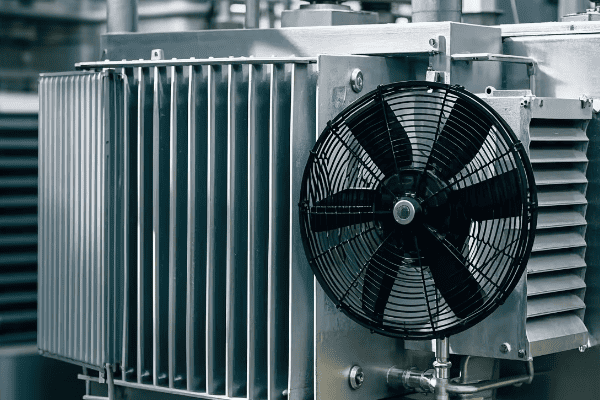
Cooling Systems: ONAN, ONAF, OFAF in Power vs. Distribution Transformers?
Have you ever touched a transformer and felt its warmth? That heat is a byproduct of transformer operation, and managing it is crucial for performance and longevity. But how do cooling systems differ between power and distribution transformers?
Power transformers often use more advanced cooling systems like ONAF (Oil Natural Air Forced) or OFAF (Oil Forced Air Forced) due to their higher capacity and heat generation. Distribution transformers typically use simpler ONAN (Oil Natural Air Natural) cooling. The choice of cooling system significantly impacts transformer size, cost, and performance.
Let’s explore the cooling systems used in power and distribution transformers. Understanding these systems is essential for proper transformer selection, operation, and maintenance.
Power Transformer Cooling
-
ONAF (Oil Natural Air Forced)
- Oil circulates naturally, fans force air over radiators
- Common in medium to large power transformers
-
OFAF (Oil Forced Air Forced)
- Oil is pumped through radiators, fans force air over them
- Used in large power transformers with high heat generation
-
ODAF (Oil Directed Air Forced)
- Oil flow is directed through winding cooling ducts
- Provides most efficient cooling for very large transformers
Distribution Transformer Cooling
-
ONAN (Oil Natural Air Natural)
- Oil and air circulate naturally
- Most common in distribution transformers
-
KNAN (Non-flammable fluid Natural Air Natural)
- Uses alternative fluids for enhanced safety
- Common in indoor or environmentally sensitive locations
| Cooling Type | Oil Circulation | Air Circulation | Typical Application |
|---|---|---|---|
| ONAN | Natural | Natural | Distribution transformers |
| ONAF | Natural | Forced | Medium power transformers |
| OFAF | Forced | Forced | Large power transformers |
| ODAF | Directed | Forced | Very large power transformers |
Cooling systems are a critical aspect of transformer design and operation. Throughout my career, I’ve worked with various cooling systems, and I’ve seen firsthand how the choice of cooling method can significantly impact a transformer’s performance, size, and cost.
Let’s start with power transformers. These units often require more advanced cooling systems due to their higher capacity and the large amount of heat they generate. One common system I’ve worked with is ONAF (Oil Natural Air Forced). In this setup, the transformer oil circulates naturally due to temperature differences, while fans force air over the radiators to enhance cooling. I remember a project where we upgraded a substation transformer from ONAN to ONAF cooling. The addition of fans allowed us to increase the transformer’s capacity without replacing the entire unit – a cost-effective solution for the utility.
For larger power transformers, OFAF (Oil Forced Air Forced) cooling is often used. In this system, pumps circulate the oil through radiators, and fans force air over them. I once worked on a 500 MVA transformer project where OFAF cooling was crucial. The amount of heat generated was so significant that natural oil circulation wasn’t sufficient. The pumps ensured efficient heat removal, allowing the transformer to operate at full capacity even in hot weather conditions.
For very large power transformers, I’ve seen ODAF (Oil Directed Air Forced) cooling used. This system goes a step further by directing the oil flow through cooling ducts in the windings. I was involved in a project with a 1000 MVA transformer using ODAF cooling. The precision in controlling oil flow allowed for extremely efficient cooling, enabling a more compact design despite the enormous power handling capacity.
The choice of cooling system in power transformers isn’t just about managing heat – it also affects the transformer’s ability to handle overloads. I’ve worked on projects where we specified transformers with multiple cooling stages. For example, a transformer might operate as ONAN under normal conditions but switch to ONAF or OFAF during peak loads or high ambient temperatures. This flexibility can be crucial for system reliability.
Moving on to distribution transformers, cooling systems are typically simpler. ONAN (Oil Natural Air Natural) cooling is the most common method I’ve encountered. In this system, both the oil and air circulate naturally. I’ve specified countless ONAN distribution transformers for residential and light commercial applications. The simplicity of this cooling method contributes to the reliability and long life of these transformers – there are no fans or pumps to maintain or fail.
However, even in the world of distribution transformers, cooling considerations can get interesting. I’ve worked on projects in urban areas where fire safety was a major concern. In these cases, we often used KNAN (Non-flammable fluid Natural Air Natural) cooling. These transformers use alternative fluids like natural esters, which have higher flash and fire points than mineral oil. I remember a project for a high-rise building where we specified KNAN transformers for their enhanced safety characteristics.
The choice of cooling system has significant implications for transformer design and operation. In power transformers, more advanced cooling allows for higher power density – you can get more MVA capacity in a smaller package. I’ve seen this be crucial in substation upgrades where space was at a premium. On the flip side, these advanced cooling systems add complexity and cost. I always have to carefully weigh these factors when specifying transformers.
For distribution transformers, the simplicity of ONAN cooling contributes to their reliability and low maintenance requirements. However, it also limits their overload capacity. I’ve been involved in studies where we had to carefully analyze load profiles to ensure ONAN transformers weren’t being pushed beyond their limits during peak periods.
One interesting trend I’m seeing is the increasing use of advanced monitoring in transformer cooling systems. Even in some larger distribution transformers, we’re now installing temperature sensors and control systems that can activate cooling fans if temperatures exceed certain thresholds. This kind of adaptive cooling can extend transformer life and increase operational flexibility.
Environmental considerations are also influencing cooling system design. In environmentally sensitive areas, the risk of oil leaks from the cooling system can be a concern. I’ve worked on projects where we’ve used biodegradable ester fluids instead of mineral oil, reducing the environmental risk. These fluids have different thermal properties, which needs to be taken into account in the cooling system design.
Noise can be another factor in cooling system selection, especially for transformers located near residential areas. ONAN systems are the quietest, while OFAF systems with their pumps and fans can be quite noisy. I once worked on a project where we had to design special low-noise fans and pump enclosures to meet local noise regulations for a large urban substation.
As we push for more efficient and compact transformers, cooling system design continues to evolve. I’m seeing interesting developments in heat pipe technology and the use of phase-change materials for transformer cooling. These innovations could lead to more efficient and reliable cooling systems in the future.
Understanding cooling systems is crucial for anyone working with transformers. Whether you’re specifying a new transformer, troubleshooting cooling issues, or looking for ways to improve efficiency and reliability, a solid grasp of these cooling principles is essential. As we continue to demand more from our electrical systems, effective thermal management in transformers will only become more important.
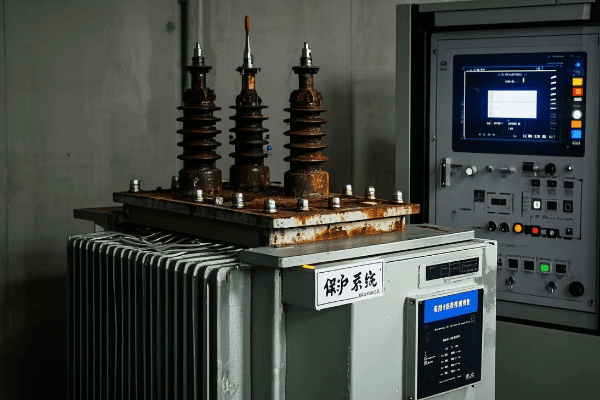
Protection and Monitoring: Specialized Systems for Power and Distribution Transformers?
Are you concerned about the reliability and longevity of your transformers? Protection and monitoring systems are crucial for preventing failures and optimizing performance. But how do these systems differ between power and distribution transformers?
Power transformers often have more sophisticated protection and monitoring systems due to their critical role and high cost. These may include differential protection, online dissolved gas analysis, and advanced temperature monitoring. Distribution transformers typically use simpler protection schemes and less extensive monitoring, focusing on overload and short-circuit protection.
Let’s explore the specialized protection and monitoring systems used in power and distribution transformers. Understanding these systems is crucial for ensuring transformer reliability and optimizing maintenance strategies.
Power Transformer Protection and Monitoring
-
Differential Protection
- Compares current entering and leaving the transformer
- Quickly detects internal faults
-
Online Dissolved Gas Analysis (DGA)
- Continuously monitors gases dissolved in transformer oil
- Provides early warning of developing faults
-
Advanced Temperature Monitoring
- Uses fiber optic sensors for direct winding temperature measurement
- Enables dynamic loading and better hot spot management
Distribution Transformer Protection and Monitoring
-
Overcurrent Protection
- Protects against overloads and external faults
- Often uses fuses or circuit breakers
-
Temperature Indicators
- Simple devices to monitor oil temperature
- May include alarms for high temperature conditions
-
Load Monitoring
- Increasingly used to track loading patterns
- Helps in planning and preventing overloads
| System | Power Transformer | Distribution Transformer |
|---|---|---|
| Fault Protection | Differential, overcurrent | Primarily overcurrent |
| Gas Monitoring | Often online, continuous | Usually offline, periodic |
| Temperature Monitoring | Advanced, multiple sensors | Basic, oil temperature |
| Load Monitoring | Detailed, often real-time | Basic, sometimes with smart meters |
Protection and monitoring systems play a crucial role in ensuring the reliability and longevity of transformers. Throughout my career, I’ve worked with a wide range of these systems, and I’ve seen how they’ve evolved to become more sophisticated and effective.
Let’s start with power transformers. These units often have comprehensive protection and monitoring systems due to their critical role in the power system and their high cost. One of the key protection systems I’ve worked with is differential protection. This system compares the current entering and leaving the transformer and can detect internal faults with high sensitivity and speed. I remember a project where differential protection detected a developing fault in a large power transformer. The quick response prevented a potentially catastrophic failure and saved millions in potential damages and outage costs.
Online Dissolved Gas Analysis (DGA) is another critical monitoring system for power transformers. These systems continuously analyze the gases dissolved in the transformer oil, providing early warning of developing faults. I once worked on a project where we installed an online DGA system on a critical 500 MVA transformer. Within months, it detected a slight increase in combustible gases, indicating a developing fault. We were able to plan an outage and address the issue before it led to a failure. The cost of the DGA system was easily justified by avoiding a major outage.
Advanced temperature monitoring is another area where I’ve seen significant developments in power transformer technology. Modern systems use fiber optic sensors to directly measure winding temperatures. I was involved in a project where we retrofitted an older transformer with a fiber optic temperature monitoring system. The detailed temperature data allowed for more accurate hot spot detection and enabled dynamic loading of the transformer, effectively increasing its capacity during cooler periods.
For distribution transformers, the protection and monitoring systems are typically simpler, reflecting their lower cost and the need for widespread deployment. Overcurrent protection is the primary form of fault protection I’ve worked with in distribution transformers. This often takes the form of fuses or circuit breakers. I remember a project where we were upgrading a residential distribution system. We had to carefully coordinate the transformer fuse ratings with the upstream protection to ensure proper selectivity.
Temperature monitoring in distribution transformers is usually more basic. Most units I’ve worked with use simple oil temperature indicators. These devices provide a visual indication of the oil temperature and may include contacts for alarm systems. While not as sophisticated as the systems used in power transformers, they provide valuable information for maintenance and can help prevent overheating.
In recent years, I’ve seen an increasing trend towards more advanced load monitoring for distribution transformers. This is often part of smart grid initiatives. I worked on a project where we installed smart meters on distribution transformers to track loading patterns. The data collected was invaluable for system planning and helped identify overloaded transformers before they failed.
One interesting development I’ve been following is the use of low-cost sensors and Internet of Things (IoT) technology for distribution transformer monitoring. I’m currently advising on a pilot project where we’re testing small, inexpensive devices that can be easily retrofitted to existing transformers. These devices monitor parameters like oil temperature, load current, and even vibration, sending data to a central system via cellular networks. While not as comprehensive as the systems used on power transformers, they provide a significant improvement in monitoring capabilities at a fraction of the cost.
The differences in protection and monitoring systems between power and distribution transformers reflect their different roles and economic considerations. For power transformers, the high cost of the unit and the potential impact of a failure justify sophisticated protection and monitoring systems. I’ve worked on projects where the protection and monitoring equipment for a large power transformer cost almost as much as a small distribution substation!
For distribution transformers, the challenge is often to find the right balance between protection, monitoring, and cost. These units are deployed in large numbers, so any additional cost is multiplied many times over. However, I’ve seen utilities increasingly recognizing the value of better monitoring, especially as they work to improve grid reliability and integrate more distributed energy resources.
Cybersecurity is an increasingly important consideration in transformer protection and monitoring systems, especially for power transformers. As these systems become more connected, ensuring their security is crucial. I’ve been involved in projects where we had to implement strict cybersecurity protocols for transformer monitoring systems to protect against potential cyber threats.
Looking to the future, I expect we’ll see continued advancements in transformer protection and monitoring technology. The trend towards more intelligent and connected systems will likely continue, with artificial intelligence and machine learning playing an increasing role in fault prediction and asset management. Whether you’re working with large power transformers or widespread distribution systems, understanding these protection and monitoring systems is crucial for ensuring the reliability and efficiency of our power systems.
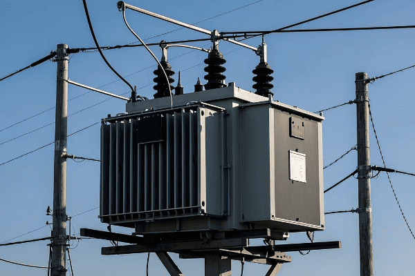
Applications in Electrical Systems: Where Are Power and Distribution Transformers Used?
Have you ever wondered about the journey electricity takes from power plants to your home? Power and distribution transformers play crucial roles in this journey, but where exactly are they used in our electrical systems?
Power transformers are primarily used in generation plants and transmission substations, handling high voltages and large power capacities. Distribution transformers are found in local distribution networks, stepping down voltage for final consumer use. Both types are essential for efficient power transmission and distribution across various voltage levels.
Let’s explore the specific applications of power and distribution transformers in electrical systems. Understanding where these transformers are used is crucial for anyone involved in power system design, operation, or maintenance.
Power Transformer Applications
-
Generation Plants
- Step-up transformers to increase voltage for transmission
- Typically increase generator voltage (15-25 kV) to transmission levels (100-765 kV)
-
Transmission Substations
- Step-down transformers to reduce voltage for sub-transmission or distribution
- Often transform from transmission voltages to sub-transmission (69-138 kV)
-
Large Industrial Facilities
- Used in facilities with their own high-voltage supply
- May step down from transmission voltages to usable levels for industrial processes
Distribution Transformer Applications
-
Residential Areas
- Pole-mounted or pad-mounted transformers in neighborhoods
- Step down medium voltage (4-35 kV) to utilization voltage (120/240 V)
-
Commercial Districts
- Often pad-mounted units serving multiple businesses
- Typically step down to 208Y/120 V or 480Y/277 V
-
Small to Medium Industries
- May use larger distribution transformers or multiple units
- Often step down to 480 V for industrial equipment
| Location | Power Transformer | Distribution Transformer |
|---|---|---|
| Generation Plants | Primary application | Rarely used |
| Transmission Substations | Common application | Not typically used |
| Distribution Substations | May be used for bulk power | Primary application |
| Residential Areas | Not used | Primary application |
| Commercial Districts | Rarely used | Common application |
The applications of power and distribution transformers in electrical systems are diverse and crucial for the efficient delivery of electricity. Throughout my career, I’ve worked with both types of transformers in various settings, and I’ve seen firsthand how they form the backbone of our power infrastructure.
Let’s start with power transformers. One of the primary applications I’ve worked with is in power generation plants. Here, step-up transformers play a critical role in increasing the voltage from generator levels (typically 15-25 kV) to transmission levels (which can range from 100 kV to 765 kV or even higher). I remember a project at a large coal-fired power plant where we were installing a new 500 MVA generator step-up transformer. The sheer size of the unit was impressive – it was as large as a small house! These transformers are crucial for efficient long-distance power transmission, as higher voltages mean lower current and thus lower losses over long distances.
Another key application for power transformers is in transmission substations. Here, they’re often used to step down voltage from transmission levels to sub-transmission levels (typically 69-138 kV) or sometimes directly to distribution voltages. I’ve been involved in numerous substation projects where we’ve installed large power transformers for this purpose. One particularly challenging project involved upgrading a suburban substation from 138 kV to 230 kV to handle increasing load demand. The new transformer not only had to handle higher voltages but also needed to fit in the existing substation footprint – a complex design challenge that required careful planning and innovative solutions.
Power transformers are also used in some large industrial facilities that have their own high-voltage supply. I once worked on a project for a large aluminum smelter that had its own 230 kV supply. We used power transformers to step this down to usable voltages for the smelting process. The unique load characteristics of the smelter, with its high current demand and potential for harmonics, made this an particularly interesting application of power transformers.
Moving on to distribution transformers, their applications are more widespread and closer to our daily lives. One of the most common applications I’ve worked with is in residential areas. These transformers are the workhorses of the distribution system, stepping down medium voltage (typically 4-35 kV) to the utilization voltage we use in our homes (120/240 V in North America). I’ve been involved in numerous projects to upgrade residential distribution systems, and the proper selection and placement of these transformers is crucial for maintaining voltage quality and reliability.
In urban and suburban settings, you’ll often see pole-mounted transformers serving a few houses each. In newer developments, pad-mounted transformers are becoming more common. I remember a project in a new subdivision where we used pad-mounted transformers housed in green boxes at regular intervals. This not only improved the aesthetics of the neighborhood but also made maintenance and replacement easier.
Commercial districts present another important application for distribution transformers. Here, the transformers are often larger and may serve multiple businesses. I’ve worked on projects in shopping centers and office parks where we’ve installed pad-mounted transformers to serve entire blocks. These typically step down to either 208Y/120 V for smaller businesses or 480Y/277 V for larger commercial buildings. The challenge in these applications is often predicting and accommodating future load growth.
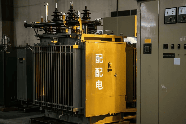
Small to medium industries also rely heavily on distribution transformers. In these settings, you might see larger distribution transformers or multiple units working together. I once worked on a project for a medium-sized manufacturing plant where we used several 2500 kVA transformers to step down from 34.5 kV to 480 V for the plant’s equipment. The diversity of loads in industrial settings, from lighting to heavy machinery, makes proper transformer sizing and protection crucial.
One interesting trend I’ve observed is the increasing use of distribution transformers in renewable energy applications. For example, in large solar farms, multiple pad-mounted transformers are often used to step up the voltage from the solar inverters before feeding into the grid. I’ve been involved in several solar projects where the selection and placement of these transformers was a key part of the system design.
The distinction between power and distribution transformers isn’t always clear-cut, especially in the middle range of voltages and capacities. I’ve worked on projects where we’ve used what the manufacturer called "small power transformers" in applications that might traditionally have used large distribution transformers. The choice often comes down to specific voltage requirements, load characteristics, and system design considerations.
Another interesting application I’ve encountered is in traction power substations for electric railways. These often use specialized transformers that could be classified as either power or distribution transformers depending on their size and the specific system design. I worked on a light rail project where we used transformers to convert utility power to the 1500 V DC used by the trains. The unique load profile of a rail system, with rapid load changes as trains accelerate and brake, made this a particularly challenging application.
In recent years, I’ve also seen an increasing focus on the role of transformers in integrating energy storage systems into the grid. Both power and distribution transformers play crucial roles here, depending on the scale of the storage system. I’m currently advising on a project where large-scale battery storage is being connected to the grid at the sub-transmission level, requiring careful consideration of transformer specifications to handle the bidirectional power flow.
The advent of smart grids is also changing how we think about transformer applications, particularly for distribution transformers. I’ve been involved in pilot projects where distribution transformers are equipped with sensors and communication capabilities, turning them into nodes in a smart distribution network. This allows for real-time monitoring of loading, voltage levels, and even power quality, enabling more dynamic and efficient grid management.
As we move towards more distributed generation and microgrids, the traditional distinctions between power and distribution transformers may become less clear-cut. I’m seeing designs for community microgrids where larger transformers (which might traditionally be classified as small power transformers) are used to interface between the microgrid and the main grid. These transformers need to handle bidirectional power flow and potentially operate in islanded mode, presenting new challenges in transformer design and application.
Understanding the applications of power and distribution transformers is crucial for anyone working in the electrical power industry. Whether you’re designing a new power system, upgrading existing infrastructure, or troubleshooting issues, knowing where and how these transformers are used is essential. As our power systems continue to evolve, with increasing renewable integration, electrification of transport, and the development of smart grids, the applications of transformers will likely evolve as well. It’s an exciting time to be working in this field, and I’m looking forward to seeing how transformer technology and applications will adapt to meet the challenges of our changing energy landscape.
Conclusion
Power and distribution transformers are crucial components in our electrical systems, each with distinct roles and characteristics. Power transformers handle high voltages and large capacities in generation and transmission, while distribution transformers step down voltage for end-user consumption. Understanding their differences in design, efficiency, cooling, protection, and applications is essential for effective power system management.
