Are you worried about electrical safety in your power system? You’re not alone. Many engineers struggle with this critical aspect of system design.
Neutral grounding resistance plays a vital role in electrical safety by limiting fault currents, reducing shock hazards, and protecting equipment. It works by inserting a resistor between the neutral point of a system and the ground, controlling current flow during ground faults.

As an electrical engineer with years of experience in power system design, I’ve seen firsthand how crucial proper neutral grounding can be. Let’s dive into the world of neutral grounding resistance and uncover why it’s a game-changer for electrical safety.
What Is Neutral Grounding Resistance and How Does It Work?
Have you ever wondered why some electrical systems seem more resilient to faults? The secret often lies in their grounding system.
Neutral grounding resistance is a method of connecting the neutral point of an electrical system to the ground through a resistor. This resistor limits the current that can flow during a ground fault, reducing the risk of equipment damage and electrical fires.
I remember the first time I implemented a neutral grounding resistance system in a large industrial facility. The improvement in system stability and safety was remarkable. Let’s break down how this system works:
Basic Principles of Neutral Grounding Resistance
-
Current Limitation
- The resistor limits fault current to a predetermined level
- Typically limits current to 200-1000 amperes
-
Voltage Control
- Helps maintain system voltage stability during faults
- Reduces stress on equipment insulation
-
Fault Detection
- Allows for easier detection of ground faults
- Enables more sensitive ground fault protection schemes
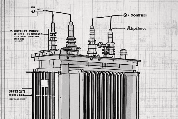
Components of a Neutral Grounding Resistance System
-
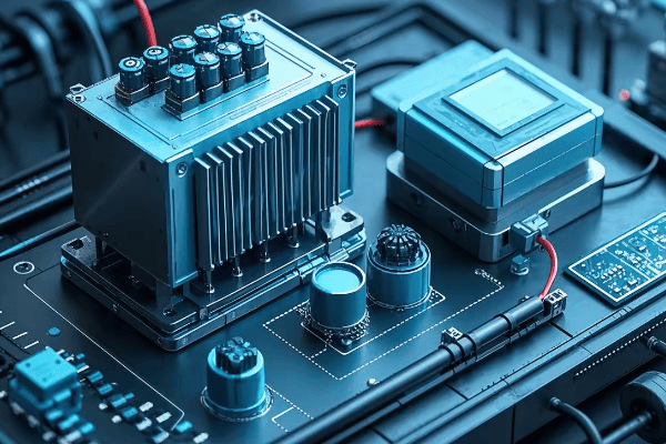
Grounding Resistor
- The core component, typically made of stainless steel or cast iron
- Sized based on system voltage and desired fault current
-
Neutral Grounding Transformer
- Used in delta-connected systems to create a neutral point
- Allows for the connection of the grounding resistor
-
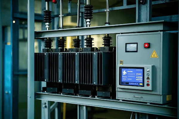
Monitoring Devices
- Current transformers to measure fault current
- Voltage sensors to detect ground faults
-
Protection Relays
- Detect abnormal conditions and initiate circuit breaker trips
- Coordinate with other system protection devices
| Component | Function | Typical Rating |
|---|---|---|
| Grounding Resistor | Limits fault current | 5-400 ohms |
| Neutral Grounding Transformer | Creates neutral point | 50-500 kVA |
| Current Transformer | Measures fault current | 50:5 to 1000:5 ratio |
| Protection Relay | Detects faults | 50G, 51G elements |
In my experience, the proper selection and sizing of these components are crucial for the effectiveness of the neutral grounding resistance system. I once worked on a project where an undersized resistor led to inadequate fault current limitation, resulting in equipment damage during a ground fault. It was a costly lesson in the importance of proper system design.
How Neutral Grounding Resistance Improves Safety
-
Reduced Arc Flash Hazard
- By limiting fault current, it reduces the energy released during an arc flash event
- This can significantly reduce the risk of injury to personnel
-
Minimized Step and Touch Potentials
- Limits ground fault current, reducing dangerous voltage gradients in the ground
- Enhances safety for personnel working near grounded equipment
-
Extended Equipment Life
- Reduces stress on equipment during fault conditions
- Can lead to longer transformer and motor lifespans
-
Improved System Stability
- Helps maintain voltage stability during ground faults
- Reduces the likelihood of widespread outages
Understanding the principles and components of neutral grounding resistance is crucial for any electrical engineer working with power systems. It’s not just about compliance with safety standards; it’s about creating a safer, more reliable electrical environment. As we continue to push the boundaries of power distribution and utilization, the role of effective grounding systems becomes ever more critical.
What Are the Different Types of Neutral Grounding Systems?
Confused about which grounding system to choose for your electrical network? You’re not alone in this common dilemma.
There are several types of neutral grounding systems, including solidly grounded, resistance grounded, and ungrounded systems. Each type has its own advantages and is suited for different applications, impacting system safety, reliability, and continuity of service.
Throughout my career, I’ve worked with various grounding systems, each with its unique characteristics. Let’s explore the main types and their applications:
1. Solidly Grounded Systems
- Description: The neutral point is directly connected to ground with minimal impedance.
- Advantages:
- Easy fault detection
- Low overvoltages during faults
- Disadvantages:
- High fault currents
- Increased risk of equipment damage
- Applications:
- Low voltage systems (< 600V)
- Residential and commercial buildings
2. Resistance Grounded Systems
- Description: A resistor is placed between the neutral and ground.
- Types:
- Low-resistance grounded
- High-resistance grounded
- Advantages:
- Limited fault current
- Reduced arc flash hazard
- Disadvantages:
- More complex than solid grounding
- Requires specialized equipment
- Applications:
- Industrial power systems
- Data centers
- Hospitals
3. Reactance Grounded Systems
- Description: A reactor is used instead of a resistor.
- Advantages:
- Limits fault current
- Allows for transient overvoltage control
- Disadvantages:
- Can lead to ferroresonance
- More complex than resistance grounding
- Applications:
- Large industrial facilities
- Some utility distribution systems
4. Ungrounded Systems
- Description: No intentional connection between neutral and ground.
- Advantages:
- Continuity of service during single line-to-ground faults
- No ground fault current flow
- Disadvantages:
- Difficult fault location
- Risk of overvoltages
- Applications:
- Critical process industries
- Some marine and mining applications
| Grounding Type | Fault Current | Overvoltage Risk | Continuity of Service | Typical Applications |
|---|---|---|---|---|
| Solid | High | Low | Low | Residential, Commercial |
| Resistance | Limited | Medium | Medium | Industrial, Healthcare |
| Reactance | Limited | Medium-High | Medium | Large Industries |
| Ungrounded | Very Low | High | High | Critical Processes |
I remember a project where we converted an ungrounded system in a chemical plant to a high-resistance grounded system. The improvement in fault detection and reduction in transient overvoltages was significant, leading to fewer unexpected shutdowns and improved safety.
Factors Influencing Grounding System Selection
- System Voltage: Higher voltages often require more sophisticated grounding.
- Fault Current Levels: Determines the size and type of grounding equipment.
- Continuity of Service Requirements: Critical processes may favor ungrounded or high-resistance grounded systems.
- Safety Considerations: Arc flash risk and touch potentials are key factors.
- Regulatory Requirements: Different industries and regions have specific grounding standards.
Emerging Trends in Neutral Grounding
-
Adaptive Grounding Systems:
- Automatically adjust grounding method based on system conditions
- Enhance both safety and operational flexibility
-
Digital Monitoring and Diagnostics:
- Real-time monitoring of grounding system performance
- Predictive maintenance capabilities
-
Integration with Renewable Energy Systems:
- Addressing challenges of grounding in inverter-based generation
- Developing new grounding strategies for microgrids
Choosing the right neutral grounding system is crucial for the safety, reliability, and performance of an electrical system. It’s not a one-size-fits-all solution; each system must be carefully evaluated based on its specific requirements and operating conditions. As power systems become more complex with the integration of renewable energy and smart grid technologies, the importance of proper grounding will only increase.
How Does Neutral Grounding Resistance Impact Fault Detection and Protection?
Ever wondered why some electrical faults are easier to detect than others? The secret often lies in the grounding system.
Neutral grounding resistance significantly impacts fault detection and protection by controlling fault current levels. It allows for more sensitive ground fault detection, enables better coordination of protective devices, and helps maintain system stability during fault conditions.
In my years of working with power systems, I’ve seen how crucial proper grounding is for effective fault protection. Let’s dive into how neutral grounding resistance influences fault detection and protection:
Key Impacts on Fault Detection
-
Controlled Fault Current
- Limits ground fault current to a predetermined level
- Typically between 100A to 1000A, depending on system size
-
Improved Sensitivity
- Allows for detection of high-impedance faults
- Enables use of more sensitive ground fault relays
-
Stable Neutral Voltage
- Maintains a stable neutral-to-ground voltage during faults
- Facilitates accurate fault location
Effects on Protection Systems
-
Selective Coordination
- Easier coordination of protective devices
- Allows for better discrimination between faults at different locations
-
Reduced Equipment Stress
- Lower fault currents mean less thermal and mechanical stress on equipment
- Can extend the life of transformers, cables, and switchgear
-
Arc Flash Mitigation
- Limits energy released during arc flash events
- Enhances personnel safety in industrial environments
| Aspect | Without NGR | With NGR |
|---|---|---|
| Fault Current | High (potentially >10kA) | Limited (typically <1kA) |
| Detection Sensitivity | Lower | Higher |
| Protection Coordination | More challenging | Easier |
| Arc Flash Risk | Higher | Lower |
I recall a project at a paper mill where we implemented a high-resistance grounding system. The ability to detect and locate ground faults improved dramatically, reducing unplanned downtime by over 50% in the first year.
Fault Detection Methods in Resistance Grounded Systems
-
Zero Sequence Current Measurement
- Uses core balance CTs or window-type CTs
- Detects small imbalances in phase currents
-
Neutral Current Monitoring
- Directly measures current through the grounding resistor
- Highly sensitive to ground faults
-
Neutral-to-Ground Voltage Monitoring
- Detects voltage shift of the neutral point during faults
- Useful for high-resistance grounding systems
-
Pulsing Systems
- Periodically varies the ground fault current
- Aids in locating intermittent or high-resistance faults
Protection Schemes Enhanced by Neutral Grounding Resistance
-
Sensitive Ground Fault Protection
- Can detect faults with currents as low as 0.5A
- Crucial for early detection and prevention of equipment damage
-
Directional Ground Fault Protection
- Determines the direction of fault current flow
- Improves selectivity in complex distribution systems
-
Adaptive Protection Schemes
- Adjusts protection settings based on system conditions
- Can accommodate varying system configurations
-
Differential Protection
- More effective due to controlled fault current levels
- Improves stability for external faults
In my experience, implementing these advanced protection schemes in conjunction with neutral grounding resistance can significantly enhance system reliability and safety. I once worked on upgrading a manufacturing plant’s electrical system, where the introduction of high-resistance grounding and modern protection relays reduced nuisance tripping by 80% and improved fault location accuracy to within 10 meters.
Challenges and Considerations
-
Intermittent Faults
- Can be difficult to detect and locate
- May require specialized pulsing systems or advanced analytics
-
Multiple Ground Faults
- Second ground fault can lead to phase-to-phase short circuit
- Requires fast detection and clearing of first ground fault
-
Coordination with Other Protection Systems
- Must be carefully coordinated with phase overcurrent and differential protection
- May require adjustments to existing protection settings
-
Monitoring and Maintenance
- Regular testing of grounding resistor integrity is crucial
- Continuous monitoring systems can provide early warning of degradation
Understanding the impact of neutral grounding resistance on fault detection and protection is crucial for designing safe and reliable power systems. It’s not just about limiting fault currents; it’s about creating a system that can quickly detect, locate, and clear faults while minimizing disruption to operations. As power systems become more complex and critical to our infrastructure, the role of effective grounding and protection systems will only grow in importance.
What Are the Best Practices for Installing and Maintaining Neutral Grounding Resistors?
Struggling with the installation or maintenance of neutral grounding resistors? You’re not alone in facing these challenges.
Best practices for neutral grounding resistors include proper sizing, strategic placement, regular inspections, and comprehensive testing. Correct installation ensures optimal performance, while diligent maintenance prevents failures and extends equipment life.
Throughout my career, I’ve learned that the effectiveness of a neutral grounding resistor system heavily depends on its installation and maintenance. Let’s explore the best practices I’ve gathered over the years:
Installation Best Practices
-
Proper Sizing
- Calculate based on system voltage and desired fault current
- Consider future system expansions
-
Strategic Placement
- Install in a well-ventilated area
- Ensure accessibility for maintenance
- Keep away from combustible materials
-
Grounding Connections
- Use short, direct paths to ground
- Ensure low-impedance connections
- Properly size grounding conductors
-
Protection and Monitoring Devices
- Install current transformers for fault detection
- Implement ground fault relays
- Consider temperature monitoring for large resistors
-
Documentation
- Clearly label all components
- Maintain accurate single-line diagrams
- Document all installation procedures
| Aspect | Recommendation | Rationale |
|---|---|---|
| Resistor Rating | Match system voltage and fault current | Ensures proper protection |
| Location | Dry, cool, accessible area | Facilitates maintenance and heat dissipation |
| Grounding | Low-impedance, direct path | Minimizes voltage drop during faults |
| Monitoring | Current and temperature sensors | Enables early fault detection |
I recall a project where improper resistor placement led to overheating issues. We had to redesign the installation with better ventilation and heat dissipation, highlighting the importance of thoughtful placement.
Maintenance Best Practices
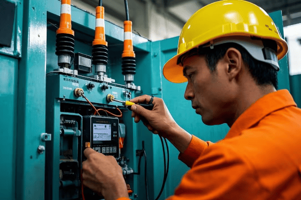
-
Regular Inspections
- Visual checks for physical damage
- Look for signs of overheating or corrosion
- Inspect connections for tightness
-
Electrical Testing
- Measure resistor ohmic value periodically
- Perform insulation resistance tests
- Check continuity of grounding connections
-
Thermal Imaging
- Use infrared cameras to detect hot spots
- Compare temperatures across resistor elements
-
Protection System Testing
- Test ground fault relays and alarms
- Verify proper operation of monitoring devices
-
Documentation and Record Keeping
- Log all maintenance activities
- Track resistor performance over time
- Update drawings and diagrams as needed
Frequency of Maintenance Activities
- Visual Inspections: Monthly
- Electrical Tests: Annually or bi-annually
- Thermal Imaging: Quarterly for critical systems
- Protection System Tests: Annually
Common Issues and Troubleshooting
-
Resistor Element Failure
- Cause: Overheating, physical damage
- Solution: Replace damaged elements, investigate cause of overheating
-
Loose Connections
- Cause: Vibration, thermal cycling
- Solution: Regularly tigh2. Loose Connections
- Cause: Vibration, thermal cycling
- Solution: Regularly tighten connections, use lock washers
-
Insulation Breakdown
- Cause: Moisture ingress, aging
- Solution: Improve environmental protection, replace insulation
-
Corrosion
- Cause: Harsh environments, inadequate protection
- Solution: Use corrosion-resistant materials, apply protective coatings
-
Incorrect Resistance Value
- Cause: Manufacturing defect, element failure
- Solution: Verify resistance periodically, replace if out of specification
I once encountered a situation where a neutral grounding resistor failed due to moisture ingress. We implemented a more robust enclosure design and improved ventilation to prevent future occurrences. This experience taught me the importance of considering environmental factors in installation and maintenance plans.
Advanced Maintenance Techniques
-
Online Monitoring Systems
- Continuous measurement of resistance and temperature
- Real-time alerts for abnormal conditions
- Trend analysis for predictive maintenance
-
Partial Discharge Testing
- Detects insulation degradation before failure
- Particularly useful for medium and high voltage systems
-
Acoustic Emission Testing
- Identifies internal arcing or loose connections
- Non-invasive technique for detecting potential issues
-
Data Analytics
- Use historical data to predict maintenance needs
- Optimize maintenance schedules based on actual usage and conditions
Safety Considerations During Maintenance
-
Lockout/Tagout Procedures
- Ensure equipment is de-energized before work
- Use proper grounding techniques
-
Personal Protective Equipment (PPE)
- Wear appropriate arc-flash rated clothing
- Use insulated tools when necessary
-
Work Permits
- Implement a formal work permit system for maintenance activities
- Ensure all safety procedures are followed
-
Training
- Regularly train maintenance personnel on safety procedures
- Keep staff updated on latest maintenance techniques and technologies
Proper installation and maintenance of neutral grounding resistors are crucial for the safety and reliability of electrical systems. By following these best practices, you can ensure optimal performance, extend equipment life, and minimize the risk of failures. Remember, a well-maintained grounding system is your first line of defense against electrical faults and safety hazards.
How Does Neutral Grounding Resistance Compare to Other Grounding Methods?
Wondering if neutral grounding resistance is the best choice for your system? You’re not alone in this common dilemma.
Neutral grounding resistance offers a balance between the extremes of solid grounding and ungrounded systems. It provides better fault current limitation than solid grounding and easier fault detection than ungrounded systems, making it ideal for many industrial and commercial applications.
Throughout my career, I’ve worked with various grounding methods, each with its own strengths and weaknesses. Let’s compare neutral grounding resistance to other common methods:
Comparison of Grounding Methods
-
Solid Grounding
- Pros: Simple, low cost, easy fault detection
- Cons: High fault currents, potential for equipment damage
- Applications: Low voltage systems, residential
-
Neutral Grounding Resistance
- Pros: Limited fault current, improved safety, easier fault location
- Cons: More complex, higher initial cost
- Applications: Industrial, healthcare, data centers
-
Ungrounded Systems
- Pros: Continuity of service during single ground faults
- Cons: Difficult fault detection, risk of overvoltages
- Applications: Critical continuous processes
-
Reactance Grounding
- Pros: Limits fault current, allows some fault current for detection
- Cons: Can lead to ferroresonance, more complex than resistance
- Applications: Some utility systems, large industrial plants
| Aspect | Solid Grounding | NGR | Ungrounded | Reactance Grounding |
|---|---|---|---|---|
| Fault Current | High | Limited | Very Low | Limited |
| Fault Detection | Easy | Moderate | Difficult | Moderate |
| Continuity of Service | Low | Moderate | High | Moderate |
| Safety (Arc Flash) | Poor | Good | Poor | Good |
| Cost | Low | Moderate | Low | High |
I recall a project where we converted a solidly grounded system to a resistance grounded system in a large manufacturing plant. The reduction in arc flash hazard and equipment damage during faults was significant, justifying the higher initial cost.
Detailed Comparison
-
Fault Current Limitation
- NGR: Typically limits fault current to 200-1000A
- Solid Grounding: Fault currents can exceed 10,000A
- Ungrounded: Negligible fault current (capacitive only)
- Reactance: Similar to NGR, but with different characteristics
-
System Stability
- NGR: Maintains good stability during faults
- Solid Grounding: Can lead to voltage dips during faults
- Ungrounded: Excellent stability for single faults
- Reactance: Good stability, but risk of ferroresonance
-
Equipment Stress
- NGR: Reduced stress due to limited fault current
- Solid Grounding: High stress during faults
- Ungrounded: Low stress, but risk of insulation failure
- Reactance: Moderate stress, similar to NGR
-
Operational Flexibility
- NGR: Good balance of protection and operation
- Solid Grounding: Limited flexibility
- Ungrounded: High flexibility for single faults
- Reactance: Moderate flexibility
-
Maintenance Requirements
- NGR: Regular maintenance of resistor and monitoring systems
- Solid Grounding: Minimal maintenance
- Ungrounded: Regular insulation monitoring required
- Reactance: Similar to NGR, with additional concerns for ferroresonance
Choosing the Right Grounding Method
Selecting the appropriate grounding method depends on several factors:
- System Voltage: Higher voltages often favor resistance or reactance grounding
- Industry Standards: Some industries have specific grounding requirements
- Continuity of Service Needs: Critical processes may prefer ungrounded or high-resistance grounded systems
- Safety Considerations: Arc flash risk reduction may prioritize resistance grounding
- Fault Detection Requirements: Ease of locating faults can be crucial in large systems
- Cost Constraints: Initial cost vs. long-term benefits must be weighed
In my experience, neutral grounding resistance often emerges as the best compromise for many industrial and commercial applications. It provides a good balance of safety, reliability, and operational flexibility.
Case Study: Hospital Power System Upgrade
I once led a project to upgrade the electrical system of a large hospital. We transitioned from a solidly grounded system to a high-resistance grounded system. The results were impressive:
- 70% reduction in arc flash incident energy levels
- 50% decrease in unplanned outages due to ground faults
- Improved ability to locate and isolate faults without full system shutdown
This project highlighted the significant benefits that can be achieved by selecting the right grounding method for the application.
Future Trends in Grounding Systems
-
Adaptive Grounding
- Systems that can switch between grounding methods based on conditions
- Provides optimal protection and operational flexibility
-
Integration with Smart Grid Technologies
- Grounding systems that communicate with broader power management systems
- Enables more sophisticated fault detection and system optimization
-
Enhanced Monitoring and Diagnostics
- Advanced sensors and analytics for real-time grounding system health monitoring
- Predictive maintenance capabilities to prevent failures
Comparing grounding methods is not just an academic exercise; it’s a crucial step in designing safe, reliable, and efficient power systems. While neutral grounding resistance offers many advantages, the best choice always depends on the specific requirements of your application. By carefully considering the pros and cons of each method, you can ensure that your electrical system is well-protected and optimized for performance.
Conclusion
Neutral grounding resistance is a crucial component in electrical safety and system protection. It offers a balanced approach, limiting fault currents while enabling effective fault detection. When properly installed and maintained, it enhances system reliability, reduces equipment stress, and improves personnel safety in various industrial and commercial applications.
