
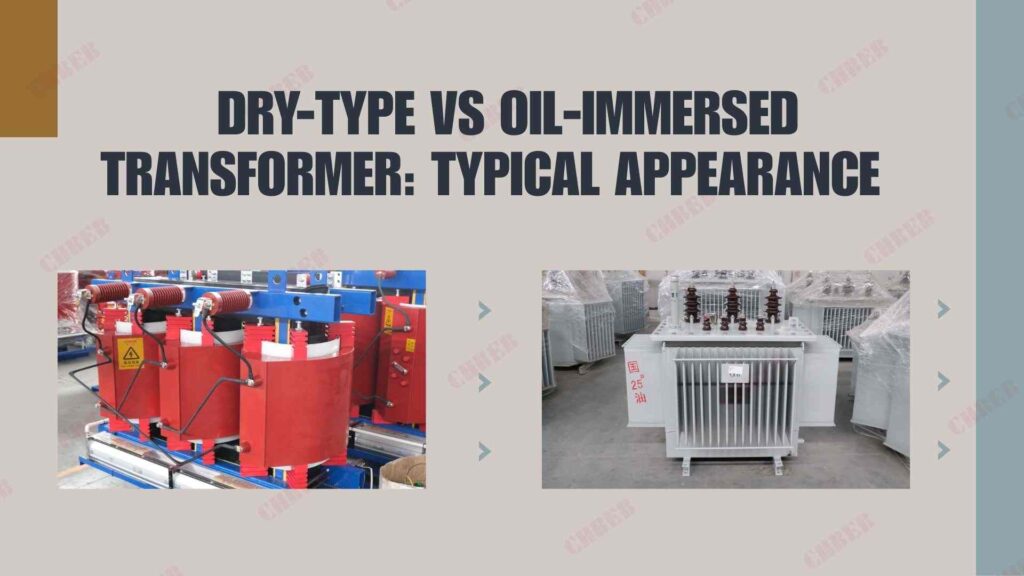
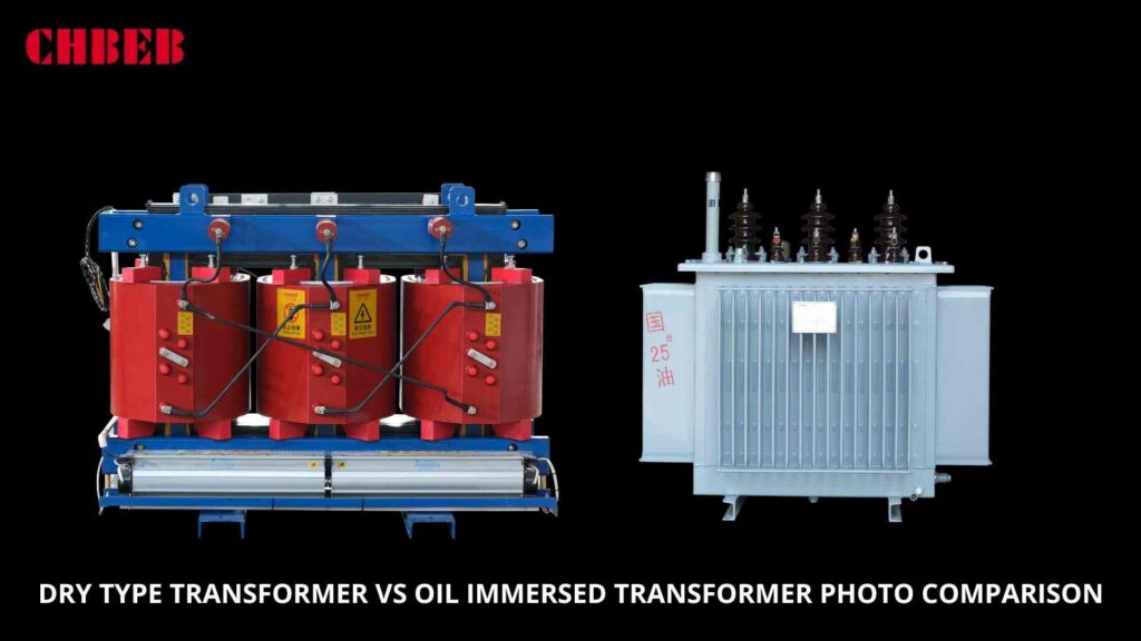
Choosing the wrong transformer causes project failures and high costs. Understanding their core differences is key to making the right choice for your power system’s safety and reliability.
The main difference is their cooling method and where they are used. Oil-immersed transformers use special oil to cool down, making them ideal for outdoor, high-power applications. Dry-type transformers use air for cooling, making them safer for indoor spaces like buildings and data centers.
On the surface, they both transform voltage. But if you look closer, their construction, manufacturing process1, and best use cases are completely different. Getting this choice right is fundamental to building a reliable and safe electrical system. Let’s dive into what really sets them apart, so you can choose the right one for your next project without any guesswork.
What is the core difference between them?
Are you confused about which transformer2 to specify for your project? Making the wrong choice leads to wasted money, project delays, and serious safety risks down the line. Let’s simplify it.
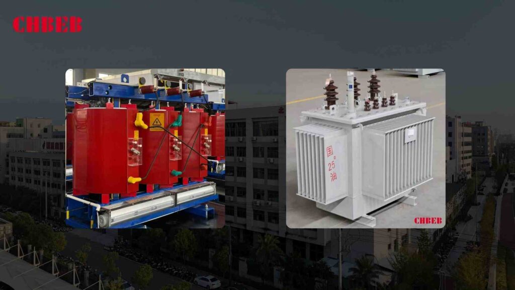
Oil-immersed transformers use oil for cooling and are built for outdoor, high-power jobs. Think of them as the heavy-duty workhorses. Dry-type transformers use air for cooling, so they are smaller, cleaner, and perfect for indoor locations where fire safety is the top priority.
To make it even clearer, I often compare them to an “outdoor giant” versus an “indoor specialist.” Each is designed for a specific environment, and using one where the other belongs is asking for trouble.
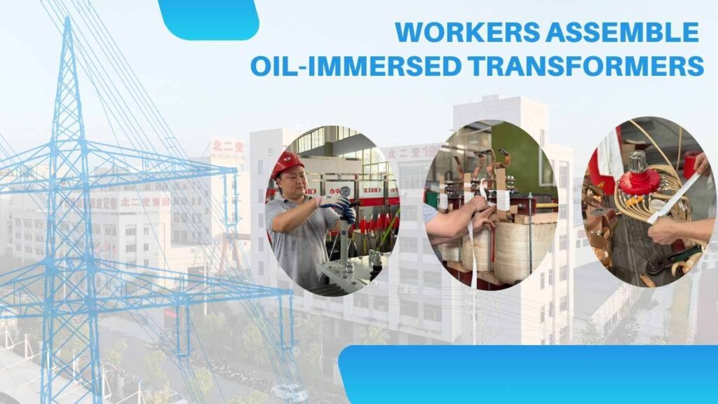
Oil-Immersed: The Outdoor Workhorse
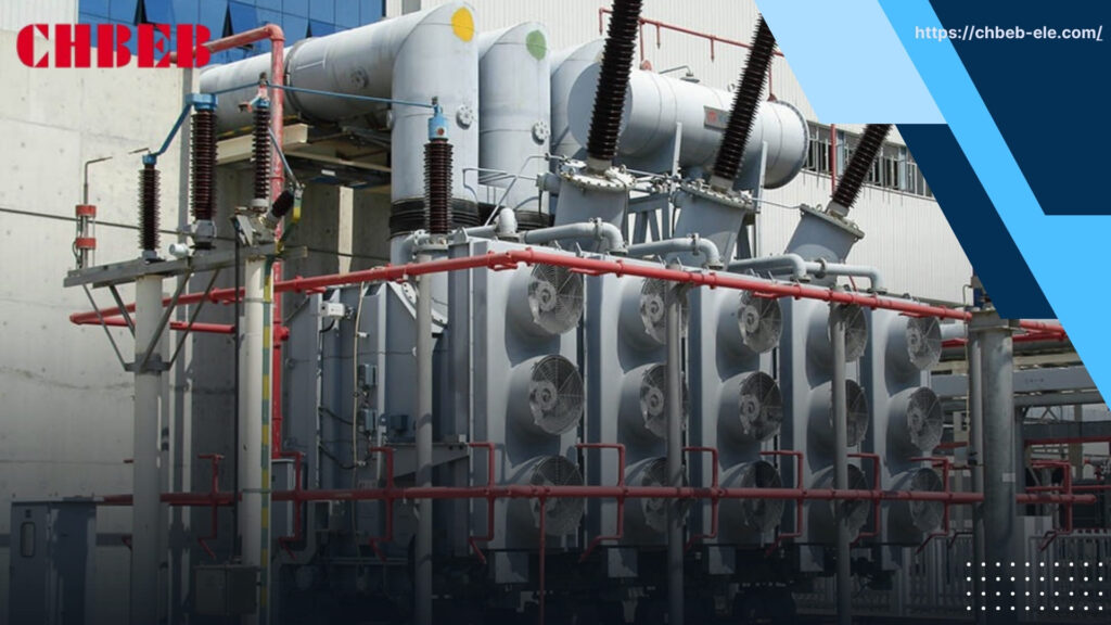
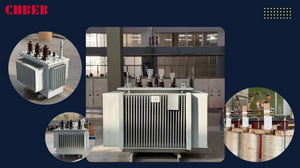
This type is a big, heavy unit filled with transformer oil. The oil serves two purposes: it acts as an insulator and, more importantly, it transfers heat away from the core and coils. This makes them great at handling large power loads and temporary overloads. You will see them everywhere outdoors—in substations powering a neighborhood, at large industrial plants, or in open-air power distribution yards. Their main drawback is the oil itself. It can leak, it is flammable, and it needs to be maintained.
Dry-Type: The Indoor Specialist
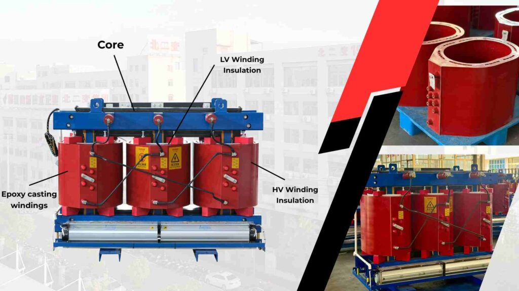
This transformer looks more like a clean, metal cabinet. It has no oil. Instead, its coils are sealed in epoxy resin and it cools itself with the surrounding air, sometimes with the help of fans. This design makes it much safer for indoor use. There is no risk of oil leaks3 or fires. That is why they are the standard choice for commercial buildings, hospitals, data centers, and factory floors. Their downside is that they are more sensitive to moisture and don’t handle overloads as well as their oil-filled counterparts.
Here is a simple table to summarize the key differences:
| Feature | Oil-Immersed Transformer | Dry-Type Transformer |
|---|---|---|
| Cooling Medium | Transformer Oil | Air (Natural or Forced) |
| Typical Location | Outdoor (substations, factory yards) | Indoor (buildings, data centers) |
| Size & Weight | Large and heavy | Smaller and lighter |
| Key Advantage | Excellent heat dissipation, high overload capacity | High safety (no oil), low maintenance |
| Key Disadvantage | Fire/leak risk, needs oil maintenance | Sensitive to moisture, lower overload capacity |
Are they equally difficult to manufacture?
Do you think all transformers are just a core with some wires wrapped around it? This simple view leads many to source from cheap factories, resulting in equipment that fails prematurely. Let’s look at the real manufacturing challenges.
No, their manufacturing is completely different and requires specialized skills. Oil-immersed transformers need perfect sealing to prevent oil leaks and fires. Dry-type transformers need advanced epoxy casting without any air bubbles to prevent electrical failure. Only experienced manufacturers can produce high-quality versions of either.

When you look inside our factory, you see that the production lines for these two types have very different critical control points. A small factory might be able to make a basic version of one, but they will not have the technology or quality control to make a reliable, high-performance model.
The Challenge of Oil-Immersed: Sealing and Purity
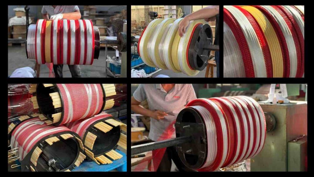
For an oil-immersed transformer, everything comes down to containing the oil. The steel tank must be welded perfectly, with no pinholes. A tiny leak can lead to a short circuit, fire, or environmental contamination. The oil itself is just as important. We filter our transformer oil at least three times to get the impurity content below 0.01%. Any more than that, and the oil could fail to insulate properly. Finally, the silicon steel sheets that make up the core must be stacked with less than 0.1mm of error. Any more, and the transformer will overheat and waste energy.
The Challenge of Dry-Type: Insulation and Casting
With a dry-type transformer, the difficulty is in the insulation. We use a high-temperature epoxy resin4 to completely encapsulate the coils. This process, called vacuum casting5, is extremely precise. It must be done in a vacuum to ensure there are absolutely no air bubbles trapped in the resin. A single bubble creates a weak spot in the insulation that can cause the coil to burn out under load. The surface of the coil also needs a special treatment to protect it from moisture. Without it, the transformer would be unreliable in humid environments.
What are their biggest weaknesses?
Every piece of equipment has a weakness. Ignoring a transformer’s “fatal flaw” can lead to unexpected downtime, expensive repairs, and dangerous situations for your personnel. Knowing these weaknesses helps you prepare and choose wisely.
The biggest fear for an oil-immersed transformer is an oil leak or oil aging, which requires costly maintenance. The biggest fear for a dry-type transformer is high heat, moisture, and dust. These conditions can destroy its insulation and cause it to fail unexpectedly.

Understanding these vulnerabilities is not about avoiding these transformers. It is about matching them to the right environment and planning the right maintenance schedule. A good plan turns a potential weakness into a manageable characteristic.
The “Achilles’ Heel” of Oil-Immersed Transformers
The main problem is, and always will be, the oil. After years of exposure to outdoor weather, the rubber seals on the tank can become brittle and crack, causing oil leaks. This is not just a maintenance headache; it is an environmental hazard that can require a full shutdown for repairs. Second, the oil itself degrades over time. After 2-3 years, it oxidizes and loses its insulating properties. It must be tested and eventually replaced, which adds to the lifetime operating cost of the transformer.
The “Achilles’ Heel” of Dry-Type Transformers
Dry-type transformers are sensitive to their operating environment. Their number one enemy is heat. If the indoor space has poor ventilation or if summer temperatures get too high, the coil temperature can exceed 155°C. This will rapidly age the epoxy insulation and drastically shorten the transformer’s life. Their other enemies are moisture and dust. In a humid or dusty place like a textile mill, moisture and dust can build up on the coils. This lowers the insulation resistance and can lead to frequent tripping or even a complete short circuit.
| Transformer Type | Primary Weakness 1 | Primary Weakness 2 |
|---|---|---|
| Oil-Immersed | Oil Leaks (from aging seals) | Oil Aging (requires replacement) |
| Dry-Type | Overheating (in poor ventilation) | Moisture & Dust Contamination |
What are the most critical manufacturing steps?
How can you tell a high-quality transformer from a low-quality one just by looking at a spec sheet? A single shortcut in the manufacturing process can cause a catastrophic failure years later. You need to know what to ask a supplier.
For oil-immersed units, the most vital step is vacuum oil filling to remove all air. For dry-type units, it is the bubble-free vacuum casting of the epoxy resin. These two steps are the most difficult to master and are what separates a world-class manufacturer from the rest.
Over my years in this business, I have seen failures that all trace back to one of these critical steps being done poorly. That is why we invest so heavily in the machinery and quality control for these specific processes. They are not negotiable.
Three Hurdles for Oil-Immersed Transformers
- Core Stacking (Foundation): The process starts with precisely stacking silicon steel sheets. If the alignment is off by more than 0.1mm, magnetic losses increase, causing the transformer to run hot and inefficiently. We scrap any core that does not meet this tolerance.
- Vacuum Oil Filling (Most Difficult!): This is the make-or-break step. We place the assembled transformer in a large vacuum chamber and inject the purified oil. The vacuum pulls every last air bubble out of the windings and insulation. Air bubbles in the oil will lead to electrical discharge and eventual failure.
- Seal Testing (Crucial): After filling, we pressurize the tank to 0.3 MPa with air and submerge it in water for 24 hours. We watch for any bubbles, no matter how small. Any unit that shows even the slightest leak is rejected and disassembled.
Three Hurdles for Dry-Type Transformers
- Coil Winding (Foundation): The copper wire must be wound tightly and evenly. Any gaps or unevenness will create hot spots on the coil when the transformer is under load, which can lead to insulation failure.
- Epoxy Resin Casting (Most Difficult!): This is our most controlled process. The mold is heated to 60-80°C, and the epoxy resin is injected very slowly under vacuum. We monitor the process in real-time to ensure the bubble rate is below 0.1%. Any higher is a safety risk.
- Insulation & Temperature Rise Test (Crucial): Every single dry-type transformer we make goes through a final test. We run it at full load until its temperature stabilizes at 155°C and keep it there for 48 hours. We monitor its insulation resistance and performance to ensure it can handle real-world stress without degrading.
Where can I find reliable transformer manufacturers?
Do you believe all manufacturers are the same? Sourcing from the wrong region can mean you get a product that is not built for your standards, uses substandard materials, and fails prematurely. Location matters.
For top-tier dry-type transformers[^6], focus on manufacturers in the Suzhou and Shanghai area, which is a hub for precision electronics. For robust oil-immersed transformers[^7], look to the industrial clusters in Taizhou and Liaocheng. Be careful with low-cost factories in other regions.

In China, different regions have developed different specialties over decades. Knowing where to look gives you a huge advantage in finding a partner who truly understands the technology you need.
The Hub for High-End Dry-Type: Jiangsu & Shanghai
This region is the heart of China’s electronics industry. Manufacturers here have access to the best epoxy resin materials and the most advanced precision casting equipment. They have deep experience meeting the demanding quality standards for data centers, high-rise buildings, and international projects. If you need a high-performance dry-type transformer for a critical application, this is where you should look.
The Hub for Robust Oil-Immersed: Jiangsu & Shandong
Manufacturers in cities like Taizhou (where one of our bases is) and Liaocheng have a long history of making heavy electrical equipment. They have perfected the processes of oil purification, tank welding, and sealing. Many top factories here, including us, use imported sealing gaskets that last three times longer than standard ones. This is the best region for sourcing large, reliable oil-immersed transformers for utility and industrial projects.
What to Watch Out For: Low-End Production
In other regions, like parts of Hebei and Henan, you will find many smaller factories focused on producing low-cost transformers. To cut costs, they often use cheaper seals, do not purify their oil thoroughly, and have bubbles in their dry-type casting. These products might work for temporary power or very low-demand situations, but they are prone to leaks and insulation failure. For any serious project, it is a risk not worth taking.
How does choosing the right transformer solve real-world problems?
Is all this technical detail just theory? A project in a harsh environment with the wrong equipment is a recipe for constant problems and budget overruns. Here is a real story of how we helped a client succeed.
We helped an Uzbekistan client by providing a custom solution for their textile park. We supplied a high-temperature-rated oil-immersed unit for outdoors and a special dust-proof dry-type unit for indoors. This solved their environmental challenges, met local standards, and cut their maintenance costs by 60%.

I remember this project clearly because the client flew to our factory with samples from their previous supplier. They were frustrated with constant failures and wanted to see our process firsthand.
The client was building a large textile park in Tashkent. They had two big challenges. First, their outdoor substation needed a 2000kVA transformer that could handle summer heat up to 44°C and frequent salt-dust storms. They were worried a standard oil-immersed unit would leak. Second, their indoor workshops needed 1000kVA transformers, but the air was filled with textile dust. They feared a standard dry-type unit would clog up and fail. On top of that, all equipment had to be UZCERT certified.
During their visit, we focused on their pain points. We showed them our oil-immersed production line, highlighting the imported high-temperature seals and our vacuum oil-filling process that gets impurity levels down to 0.005%. We even ran a 48-hour test for them in a 45°C environmental chamber, and the transformer showed zero leaks. For the dry-type unit, we demonstrated our bubble-free casting and a special anti-dust coating we apply to the coils. We did a live dust-spray test, and the insulation resistance remained perfect.
The client was convinced. They saw our UZCERT documents and that our product labels and manuals were already in Uzbek. They signed a three-year supply contract on the spot. Two years later, they told me, “The outdoor transformer hasn’t leaked a drop of oil, and the indoor one has never tripped. Your products are perfectly adapted to our environment, and our maintenance costs are down 60%.”
Conclusion
Choosing between oil-immersed and dry-type transformers is about matching the product to the application. Understanding their differences in cooling, manufacturing, and weaknesses ensures you select a reliable and cost-effective solution.
⚙️ CHBEB — Reliable Partner for Dry Type Distribution Transformers

When it comes to dry type transformer manufacturing, CHBEB stands among China’s most experienced and trusted suppliers. With over 60 years of transformer production expertise, the company has mastered both technical precision and global reliability — serving utilities, EPC contractors, and industrial buyers worldwide.
Our Manufacturing Network
CHBEB operates two factories in Wenzhou, one in Nanjing, and a Beijing office, ensuring large-scale production capacity and fast global delivery. Each factory is equipped with advanced VPI and Cast Resin production lines that comply with IEC 600762, ISO9001, and CE standards.
Why CHBEB for Dry Type Transformers:
- High-End Materials: Every unit uses 100% new copper, Class F/H insulation, and premium silicon steel for maximum efficiency.
- Full Testing Assurance: All dry type transformers undergo strict routine and type tests — including insulation resistance, partial discharge, and temperature rise.
- Proven Reliability: CHBEB is a qualified supplier for the State Grid Corporation of China, maintaining a zero-accident record in global projects.
- Fast OEM/ODM Service: From prototype to batch delivery, customized orders can be completed in as little as one week for urgent projects.
- Global Focus: With exports to Russia, Southeast Asia, Africa, and Belt & Road countries, CHBEB supports local distributors and contractors with on-site service and certification assistance.
- Green Manufacturing: Our dry type transformers are designed for fire safety, low noise, and eco-compliance, ideal for hospitals, schools, and renewable energy systems.
💡 Looking for a reliable dry type transformer manufacturer that combines Chinese manufacturing strength with international quality?
👉 Contact CHBEB today at [email protected] or visit www.chbeb-ele.com to get your customized solution or download our full dry type transformer catalog.
- Understanding the manufacturing process can help you identify quality transformers. ↩︎
- Understanding the various type of transformer can help you choose the right one for your project. ↩︎
- Explore the causes of oil leaks to better maintain and choose oil-immersed transformers. ↩︎
- Learn about epoxy resin’s importance in ensuring the reliability of dry-type transformers. ↩︎
- Understand the vacuum casting process to appreciate its role in transformer quality. ↩︎
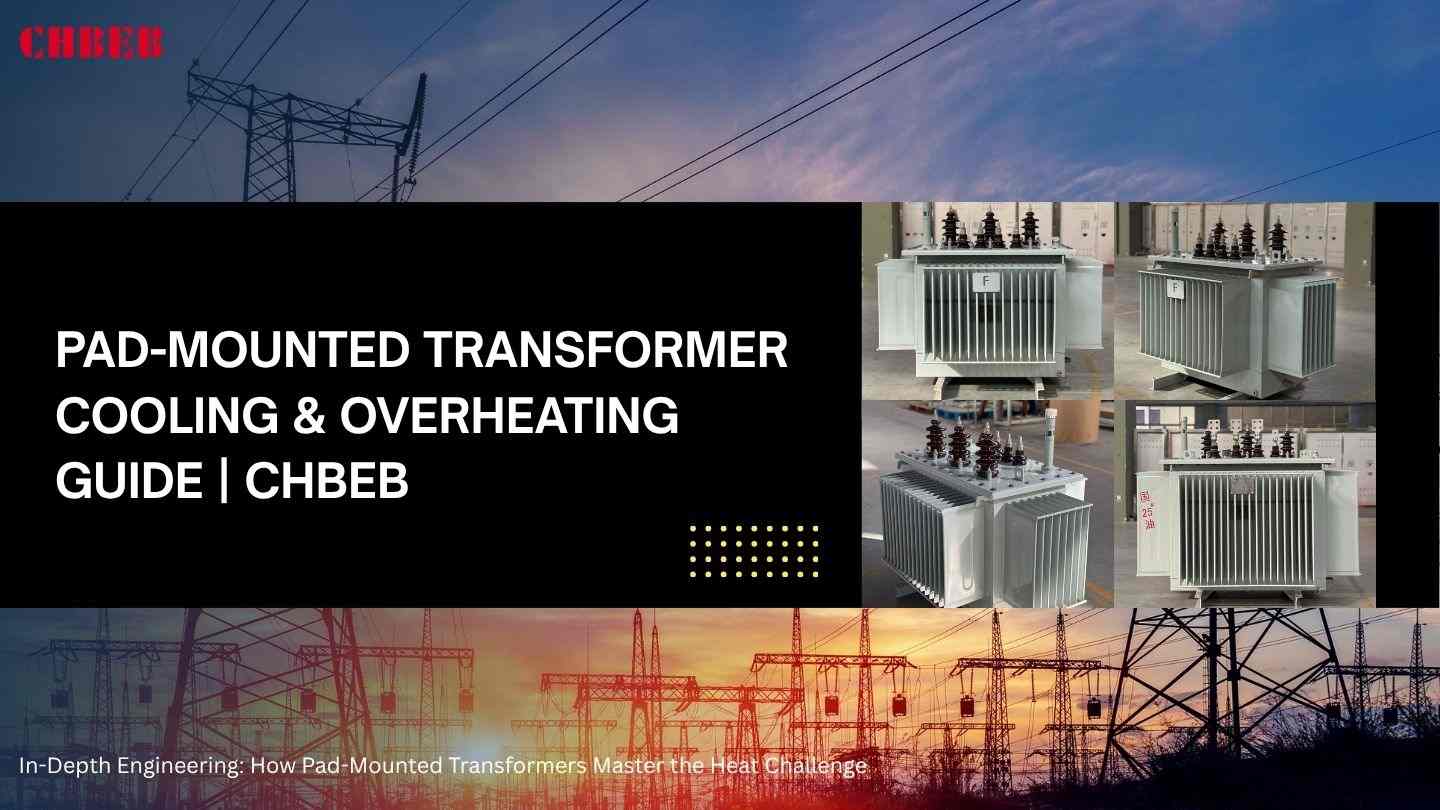
In-Depth Engineering: How Pad-Mounted Transformers Master the Heat Challenge
Introduction
In residential, business, and utility networks, pad-mounted transformers function quietly, but they are always combating heat. As heat builds up inside a sealed enclosure, the insulation weakens, efficiency drops, and the risk of overheating increases. This article explains how pad-mounted transformers use physics, materials, and design to manage heat, ensuring long-term reliability in real-world conditions.
Thermal Fundamentals: Heat Generation, Transfer Paths, and Cooling Mechanism
When purchasers think that small oil-immersed pad-mounted units run cool on their own, heat becomes a concern. In reality, every watt of loss turns into heat that becomes trapped inside a metal cabinet. This is one of the main challenges of pad-mounted transformer cooling. Anyone specifying, designing, or servicing these units must understand how heat forms, flows, and exits the system.
Heat Sources: Decomposing No-Load Losses, Load Losses, and Heat Generation
Transformers that are buried or have limited airflow need stricter control of temperature rise than units installed in open-air environments.
No-load losses — the heat source that never stops
The magnetic core of the transformer generates no-load losses, including:
- Hysteresis losses caused by the changing magnetic field
- Eddy current losses1 moving through the silicon steel
These losses keep pad-mounted transformers continuously warm, regardless of how much power they are delivering.
Load Losses: The Most Important Heating Factor
I²R losses occur when current flows through the windings due to the resistance of the copper.
- More load → more heat
- Overload → rapid increase in transformer temperature
- Harmonics → extra heating in both the winding and structural parts
Many field technicians search “why is my pad-mounted transformer overheating” because even small overloads can push temperatures inside a sealed enclosure far beyond the design limit.If you want a deeper understanding of how transformer insulation and oil behave under rising temperature, you may also refer to our guide “Unlocking Transformer Oil’s Superpowers: Why Is Oil Essential for Transformer Operation?” — it explains how oil aging, oxidation, and moisture all accelerate heat-related failures.

Losses from stray and harmonic waves
When stray flux interacts with structural metal parts, it produces localized hotspots that raise the temperature inside a pad-mounted transformer.
Modern loads such as EV chargers, inverters, and commercial drives introduce harmonics that significantly increase losses. If not controlled, these harmonic effects can shorten the lifespan of pad-mounted transformers.
Transfer Path: The Oil-Immersed Transformer’s Three-Step Cooling (Conduction–Convection–Radiation)
The reliability of an oil-immersed pad-mount transformer depends on how well it handles three cooling stages:
1. Conduction: Heat Moves into the Oil
Windings and the core transfer heat into the transformer oil. The efficiency of this stage depends on:
- Hot oil rises
- Cool oil sinks
- Vertical ducts and proper geometry ensure smooth flow
Any blockage disrupts circulation, causing the transformer to heat up faster and age more quickly.
2. Convection: Oil Moves Around and Moves Heat Up
Natural convection circulates oil in ONAN systems:
- Hot oil rises
- Cool oil sinks
- Vertical ducts and proper geometry ensure smooth flow
Any blockage disrupts circulation, causing the transformer to heat up faster and age more quickly.
3. Radiation: Heat escapes the tank and enters the air around it.
When heat reaches the tank wall, it transfers to the surrounding air. Pad-mounted transformers rely heavily on:
- Cooling fins
- High-emissivity coatings
- Adequate airflow inside the pad enclosure
If airflow is restricted, pad-mounted transformer cooling becomes the limiting factor.
Design and Longevity: Hot Spot Control and Dynamic Load Management
Heat is most harmful when it concentrates in hot spots. If the temperature limit of a pad-mounted transformer is reached, insulation life drops very quickly.
Arrhenius Law2 and Why Hot-Spot Control Matters
Arrhenius’s thermal-aging principle states:
Every 6 °C increase in hotspot temperature cuts insulation life in half.
To manage this risk, companies use:
- IEEE/IEC thermal models
- Fiber-optic temperature sensors
- Digital twins that simulate IEEE C57.91 pad-mount temperature rise
These tools help identify worst-case hotspots before production.
Choosing the right materials and insulation
The quality of the material affects how long it can last under heat:
- AAramid paper can endure higher temperatures than cellulose paper.
- Natural and synthetic ester oils can handle more heat stress.
- Class H insulation supports higher pad-mount hot-spot temperatures.
Better insulation means the pad-mounted transformer will last longer.

Harmonics, overload, and environmental stress
Pad-mounted transformers now face higher thermal stress because of:
- EV charging loads
- Solar PV inverters
- Unbalanced three-phase demand
- High urban ambient temperatures
These factors can cause unexpected overheating, especially in sealed cabinets with limited airflow.
Practical Application: Thermal Optimization and Monitoring
Pad-mounted transformers are only reliable when the heat is always kept in check. Some of the best ways in the business are:
Fin and Radiator Optimization
Manufacturers make cooling work better by changing:
- Fin height and depth
- Space between radiators
- The shape of the air channel
- Emissivity of thermal coating
Better fins mean that the temperature of the transformer rises less.
Internal Oil Duct Engineering
Oil ducts that are made the right way:
- Increase convection circulation
- Prevent stagnant hot-oil pockets
- Reduce hotspot acceleration
Good duct design is essential for stable cooling in a pad-mounted transformer.
Active Cooling Solutions
Most pad-mounted devices use natural cooling, but when the load is high, they may require:
- Air-blowing fans
- Smart thermostats
- Ester oils that tolerate higher temperatures
These enhancements help prevent the pad-mounted transformer from overheating during peak load conditions.
Digital Monitoring and Predictive Control
Real-time monitoring is used by modern pad-mounted transformers:
- Hot-spot sensors
- SCADA-based temperature monitoring
- Predictive analytics for forecasting overloads
This turns the transformer from a passive asset into an actively monitored component, helping prevent failures before they occur.
Pad-Mounted Transformer Overheating — Common Buyer Questions Answered
“Why is a pad-mounted transformer hotter than a transformer in a substation?”
Because pad-mounted units have less room to move about. A regular substation transformer features big radiators, open air, and good airflow.
A pad-mount is inside a sealed metal cabinet that doesn’t get much airflow and is often warmer near the ground.
Higher temperature rise when there is less airflow and the same losses.
This is totally normal as long as the unit stays within its temperature range.
“What is the highest temperature that a transformer can safely reach at a hot spot?”
Most oil-immersed pad-mounted transformers follow the same rules as IEC and IEEE standards:
- 110°C hot spot for mineral oil
- Natural ester oil has a hot spot between 120 and 130°C.
If the pad-mount hot-spot stays above these limits for a long time, the insulation will age much faster.
Short peaks are fine. Long peaks are not.
“How does high temperature really shorten the life of a transformer?”
Heat is the murderer that doesn’t make noise.
Arrhenius’s laws for aging say:
Every 6–7°C rise in the temperature of a hot spot roughly cuts the life of insulation in half.
High heat dries up insulation, oxidizes oil, raises acidity, and lowers dielectric strength. This is why controlling the temperature is one of the most important factors affecting how long a pad-mounted transformer lasts.
“How do engineers figure out how hot a transformer gets?”
It usually originates from two parts:
- Load losses → find out how much the winding temperature rises
- Core losses → find out how much the oil temperature goes up
Manufacturers use both thermal models (IEEE C57.91) and practical tests:
- Indicators for winding temperature
- Measurements of top oil
- Hot-spot multipliers
The end result is a difference between the calculated and measured temperature rise at rated load. This ensures the device stays within safe limits.
“Do harmonics really make a transformer hotter?”
Of course, especially in networks today.
Harmonics from PCs, EV chargers, VFDs, and inverters increase:
- Eddy-current losses
- Stray-flux heating
- Non-sinusoidal current
This extra heat often doesn’t show up in simple load calculations. That’s why environments with high harmonics sometimes need a K-factor-rated transformer, better oil circulation, or larger cooling capacity.
“How does ONAN cooling really work in a pad-mounted transformer?”
What ONAN stands for:
Oil Natural → oil moves about on its own
Air Natural → air naturally cools the radiator
The hot oil rises to the top, cools off in the radiators, and then descends back down.
No pumps. No fans.
It’s easy to use, dependable, and quiet, but it also means the transformer depends on:
- Oil duct design
- Free passage of air
- Good arrangement of fins and radiators
If there is a blockage or limited airflow inside the pad enclosure, the temperature can go up.
“What is the normal oil temperature while the machine is running?”
Normal ranges in the field:
- Top oil temperature between 45–65°C under normal load
- 70–85°C during high load or hot weather
- 90–100°C in rare cases (acceptable only for short periods)
What matters most is not the total number, but:
- The rate of increase
- The hot-spot temperature
- Whether the temperature stays stable or keeps rising
A pad-mounted transformer that warms up and then stabilizes is good.
A unit that keeps heating up continuously needs to be checked.
⚙️ CHBEB — Real Engineering Behind Every Pad-Mounted Transformer
At CHBEB, we don’t rely on generic designs or outsourced assembly.
We engineer pad-mounted transformers with real thermal science — the kind that survives harsh climates, harmonic-heavy networks, and urban distribution loads.
What makes CHBEB different?
🔹 We understand heat.
Every design is built with IEEE C57.91 thermal modeling, optimized oil ducts, and verified hot-spot calculations.
🔹 We are more reliable than typical Chinese factories.
Our transformers go through full temperature-rise testing, not just routine tests.
🔹 We’re a practical, battle-tested manufacturer.
No exaggerated claims. Every rating, test, and drawing is backed by real factory capability.
🔹 We support your project like an engineering partner, not just a supplier.
Load analysis, harmonic assessment, cooling checks, installation environment review — we handle them with you.
🔹 We do true OEM/ODM with international standards.
IEC 60076, IEEE C57, ANSI, CE — all supported, with documented compliance.
This is why CHBEB transformers run reliably across Southeast Asia, the Middle East, Africa, Russia/CIS, and utility networks worldwide.
When heat control matters, CHBEB delivers transformers that stay cool, stable, and safe.
👉 Looking for a distribution transformer manufacturer that combines Chinese manufacturing strength with international standards?Contact CHBEB for a tailored solution or Download our full transformer catalog here.

Conclusion
Heat is the number one factor that determines whether a pad-mounted transformer operates reliably or fails early. When buyers understand how pad-mounted transformer cooling works — from oil circulation and fin design to hot-spot behavior and IEEE temperature-rise limits — they can choose equipment that stays stable even under overload, harmonics, and harsh ambient conditions.
For project owners, EPC contractors, and utility engineers, proper control of pad-mounted transformer temperature rise is more than a technical requirement — it directly affects insulation life, long-term operating cost, and grid reliability. By evaluating cooling design, hotspot limits, harmonic impact, and enclosure airflow before purchase, buyers can avoid overheating issues, extend transformer lifespan, and reduce unexpected outages in the field.
China Power Transformer Market Survey: Sourcing HV Capabilities and International OEM Solutions
Introduction
It can be hard to buy high-voltage transformers from China since there are so many factories, too many claims about what they can do, and not enough information. When a bad choice can put off the whole substation, purchasers need to know exactly who can install HV equipment and how to check their skills. This guide will help you understand.
Capability Verification: Manufacturer Qualifications, Technical Barriers, and OEM Solutions
It’s not hard to find a factory that makes transformers. The tricky thing is finding one that can really make HV-grade (110–220 kV) equipment. A lot of suppliers say they can do HV on paper, but they really depend on outsourcing or third-party test labs. This part helps purchasers tell the difference between true capabilities and marketing noise.
Market Landscape: State-Owned Giants vs. Specialized Private Enterprises
There are two main groups that shape China’s HV transformer industry: state-owned enterprises (SOEs) and private HV producers that focus on exports. Their roles, capabilities, and ideal project types are all very different.
✅ Market Positioning Overview(表格对比)
| Category | State-Owned Giants (SOEs) | Specialized Private HV Manufacturers |
|---|---|---|
| Representative Companies | TBEA, XD Group, Baoding, Shenyang | Export-focused 35–220 kV factories |
| Voltage Capability | 220–1000 kV (UHV leader) | 35–220 kV (main export range) |
| Core Strengths | Full HV labs, impulse platforms, national EPC capability | Fast response, OEM/ODM customization, flexible standards |
| Project Type | National grid, UHV, mega energy projects | International utilities, industry substations, data centers |
| Lead Time | Longer (government cycle) | Faster (commercial cycle) |
| Customization | Limited | Strong (OEM/ODM friendly) |
| Pricing | High | Moderate / optimized |
| Ideal For Buyers | Ultra-high voltage projects, government EPC | Export projects needing flexibility, standards compliance, and OEM solutions |
✅ Summary
- SOEs are suitable for government EPC projects and ultra-high-voltage (330–1000 kV) projects.
- For international 35–220 kV, OEM/ODM, industrial substations, and fast-delivery needs, specialized private businesses are the best choice.
Private HV manufacturers offer the best mix of price, performance, and flexibility for 80% of buyers around the world.
Technical Depth: HV Manufacturing Barriers, Partial Discharge Control, and HV Test Labs
Making high-voltage transformers requires a lot more than just bigger tanks and thicker copper. To really have HV capacity, you need to get beyond four engineering problems:
✅ 1. High-precision insulation engineering – creepage distance, radial insulation, interlayer strength
✅ 2. Partial discharge control – PD < 5 pC at rated voltage
✅ 3. HV core and winding accuracy – step-lap steel, tension control, burr suppression
✅ 4. High-voltage test infrastructure – impulse tests, induced AC tests, temperature-rise platforms

A real HV factory MUST have:
- Lightning impulse test lab
- Induced overvoltage test capability
- PD test room ≤ 5 pC
- Full temperature-rise test platform
- Routine IEC/IEEE acceptance test capability
A major danger for purchasers from other countries is that a supplier may not be able to show original test records, HV lab photos, or videos of actual testing.
Collaboration & Procurement: Quality Compliance, Acceptance Protocols, and Supply Chain Management
Even when capability is established, controlling standards, testing, documentation, logistics, and production risk is still necessary for successful HV procurement.
International Standards: Ensuring compliance with IEEE, IEC, and target-grid rules
Most of the time, transformers are rejected for shipment not because of hardware issues, but because they don’t meet the required standards.
HV transformers must comply with the electrical code of the destination country, not the supplier’s default standards.
✅ Key Regional Standards Overview(表格对比)
| Region | Standard Framework | Special Requirements |
|---|---|---|
| Middle East | IEC 60076 + Utility Specs | High ambient, sand/dust, PD stability |
| North America | IEEE C57 Series | Cooling class, OLTC logic, NEMA enclosure |
| Africa | IEC + local addenda | Grounding, overload conditions |
| Southeast Asia | IEC + tropical version | Humidity control, corrosion resistance |
A true OEM supplier will adapt:
- Core steel grade
- HV insulation clearances
- OLTC/DETC options
- Cooling class (ONAN/ONAF/OFAF)
- Accessories required by grid code
Real compliance is proven through:
✅ Third-party witnessed FAT reports
✅ Previous export references
✅ Type-test certificates
Not through brochures or marketing statements.
Risk Control: FAT Acceptance, Lead Time Management, and Full Life-Cycle Support
There are many high-risk moments in the process of buying an HV transformer. Strong providers aid buyers through every step.
✅ 1. FAT (Factory Acceptance Test)
A complete FAT should include:
- Winding resistance, ratio, vector group
- No-load & load loss measurement
- PD test at rated voltage
- Applied voltage / induced voltage test
- OLTC mechanical & electrical inspection
- Temperature-rise test (where applicable)
FAT can be:
- Customer-witnessed onsite
- Third-party witnessed (SGS / BV / TÜV)
- Livestreamed with real-time measurement screens
✅ 2. Lead Time & Production Risk
Typical manufacturing cycles:
| Voltage Class | Average Lead Time |
|---|---|
| 110 kV | 90–120 days |
| 132–150 kV | 120–150 days |
| 220 kV | 150–210 days |
Key risk factors:
- Core steel procurement
- OLTC delivery schedule
- HV lab queue time
- Oversized packing preparation
Reliable suppliers issue weekly QC progress reports.

✅ 3. Life-Cycle Support
Long-term reliability after installation depends on more than just manufacture; it also depends on assistance.
Strong OEM suppliers provide:
- Oil testing frequency guidance
- OLTC maintenance schedule
- Condition monitoring recommendations
- Emergency support response within 24 hours
- Remote diagnostics or onsite service (region-dependent)
Friendly, Buyer-Focused FAQ: What Global Buyers Really Want to Know
1. “Who makes the most transformers in China?” Do I have to buy from them?
Most people instinctively think of TBEA and XD Group, and certainly, they are the major companies operating China’s 220–1000 kV grid.
But many new buyers don’t realize this:
👉 You don’t need a national giant unless your project is UHV-level.
For export projects between 110–220 kV, specialized private HV manufacturers often provide you:
- Faster lead time
- More flexible engineering
- Real OEM customization
- Much better pricing
Same technological skills, but without the huge government bureaucracy.
2. “Can Chinese manufacturers really produce 220 kV or even 500 kV transformers?”
Yes, absolutely — but not every factory that claims ‘HV capability’ actually has it.
A real HV-capable factory will be very open about showing:
- Their high-voltage impulse test hall
- PD readings (≤5 pC) shown live on camera
- Photos or videos of previous 110–220–500 kV projects
- Third-party witnessed test reports (SGS / BV / TÜV)
If a supplier hesitates or can’t show proof, that’s your signal to walk away.
3. “How do I verify that their HV test lab is real, not just marketing photos?”
Here’s what experienced EPC buyers do:
✅ Ask for a live video walk-through, not just pictures
✅ Request original impulse and PD test reports (not screenshots)
✅ Ask for real-time PD readings during a call
✅ Send SGS/BV if the project is critical
A legitimate factory will never refuse — they’re usually proud to show their test bay.
4. “Where does FAT usually happen for big transformers? Can it be done externally?”
FAT for HV transformers must happen in the manufacturer’s own test hall — HV test equipment cannot be moved.
A proper FAT includes:
- Ratio, vector group, and winding resistance
- No-load + load losses
- Induced & applied voltage tests
- Partial discharge
- OLTC operation
- Temperature-rise (for large units or per spec)
Good suppliers will stream the entire FAT live, with on-screen measurements — this is now standard for overseas projects.
5. “Can a Chinese transformer really meet IEEE / ANSI requirements?”
Yes — but only if you choose the right supplier.
China has factories that:
- Export to North America
- Build fully IEEE C57-compliant units
- Use NEMA-rated enclosures
- Follow ANSI cooling and OLTC logic
If your supplier cannot show previous IEEE export records, choose one who can.
IEEE compliance is not difficult — experience is the real differentiator.
6. “How long is the lead time for an OEM HV transformer?”
Typical timelines:
- 110 kV: 90–120 days
- 132–150 kV: 120–150 days
- 220 kV: 150–210 days
Delays usually come from:
- OLTC delivery (MR/Reinhausen parts)
- Core steel supply
- Test-lab scheduling for impulse tests
A trustworthy OEM factory will give weekly updates with photos — so you always know what stage your transformer is in.
7. “How do you ship a heavy transformer safely over long distances?”
For big units, the logistics matter almost as much as the manufacturing.
Most exports use:
- Flat Rack (FR) for 20–60 tonne units
- Break Bulk for oversized cargo
- RoRo when mounted on a platform
- Low-bed trailers + escorts for inland transport
The important part?
👉 Vibration recording
👉 Moisture protection
👉 Center-of-gravity calculation
👉 ICC-A marine insurance
A good supplier will prepare all of this automatically — not wait for you to ask.
⚙️ CHBEB — Reliable Partner for Substation and Power Transformer Solutions
In the transformer industry, not every manufacturer truly understands how to apply IEEE C57.91 in real design work, thermal modeling, or FAT validation.
For CHBEB, this knowledge is not theoretical — it is built from decades of experience.
Over the past 60 years, CHBEB has grown from a small winding workshop into a multi-facility transformer manufacturer, with two factories in Wenzhou, a complete assembly plant in Nanjing, and an international operations center in Beijing. We supply oil-immersed and dry-type transformers to utilities, EPC contractors, and industrial clients worldwide — and many of them first came to us because they needed a partner who could help them solve challenges related to standards, climate adaptation, or compliance.
What we focus on is simple:
make the engineering clear, make the risks visible, and make every transformer traceable — from thermal performance to climate suitability.
For oil-immersed transformers, our capabilities include:
- ONAN / ONAF / OFAF thermal design
- Hot-spot and top-oil simulations based on IEEE models
- A 50 MVA temperature-rise test platform
- 110–220 kV impulse and AC withstand capability
- Derating and thermal correction for desert and tropical climates
For dry-type transformers, our facilities operate:
- VPI and Cast Resin production lines
- <5 pC partial discharge control
- Class F and H insulation systems
- Custom design for distribution and industrial applications
Compared with large state-owned enterprises, our strength often lies in flexibility:
Need a non-standard voltage? We can build it.
Need IEEE and IEC thermal logic unified into one FAT report? We’ll prepare it for you.
Tight schedule? We prioritize your test bay time to reduce waiting.
Complex climate or grid requirements? We calculate all Annex-B or regional derating factors and integrate them into the design.
Clients who work with us know that CHBEB’s value is not “selling a transformer.”
It is ensuring that every step — design, testing, packaging, shipping, commissioning — stays under control and with full transparency.
This is why CHBEB transformers operate reliably across Russia, Southeast Asia, the Middle East, Africa, and other demanding environments. From 50 kVA units to 220 kV substation transformers, each one reflects a long-term commitment rather than a one-time transaction.
If your project involves IEEE or IEC compliance, thermal verification, FAT witness tests, climate adaptation, or custom engineering, we aim to be the technical team you can ask, trust, and rely on — anytime.
👉 Looking for a distribution transformer manufacturer that combines Chinese manufacturing strength with international standards?Contact CHBEB for a tailored solution or Download our full transformer catalog here.
Conclusion
China’s HV transformer market is wide, but true capability is narrow. The real challenge for overseas buyers is not choosing a factory — it is verifying who can genuinely build, test, and certify 110–220 kV equipment without outsourcing or risking compliance failure.
By focusing on three essentials — capability verification, standards alignment, and full FAT transparency — buyers can reduce project risk, avoid costly delays, and secure long-term grid reliability. State-owned giants remain unmatched for UHV projects, but for 35–220 kV export applications, specialized private HV manufacturers offer the optimal balance of performance, customization, and delivery speed.
With structured supplier evaluation and strict acceptance protocols, importing high-voltage transformers no longer needs to be a gamble. Choosing partners who provide real test data, real engineering depth, and real accountability is the key to ensuring every unit that leaves China arrives ready for safe, certified operation in your grid.
Understanding IEEE Guide C57.91 for Loading Mineral-Oil-Immersed Transformers
Introduction
If you’ve ever been next to a buzzing transformer on a hot summer afternoon and thought, “Can I push this thing a little harder?” — The answer is IEEE C57.911. It’s not a textbook; it’s the industry’s guide to how much oil you can put in a transformer before it starts to age too quickly.
What C57.91 Covers: Scope, Thermal Model, and Loading Categories
IEEE C57.91 doesn’t tell you how to make a transformer; it informs you how to use one. It’s about finding the right balance between heat, insulating life, and real-world performance.
Scope and Assumptions (65 °C system and related IEEE standards)
The tutorial is about transformers that are bathed in mineral oil and have an insulating system that can handle 65 °C. These are the workhorses of the grid. It is related to standards such as IEEE C57.12.00 (design) and IEEE C57.104 (gas analysis).
The assumptions are easy to understand yet important:
- Ambient temperature is roughly 30 °C (normal service condition)
- Normal oil flow (ONAN/ONAF cooling)
- Steady loading, no big spikes or short bursts
In real life, though, a lot of grids operate hotter than that, especially in the Middle East, Africa, and Southeast Asia. This is when engineers start to deliberately bend the “book values.”
Thermal Basics: Top Oil, Hot Spot, and Aging Factor
The guide’s thermal model is based on three temperatures that all operators should be aware of:

- Top-oil temperature (TOT) is the average temperature of the oil in the tank.
- The warmest place in the windings is the hot-spot temperature (HST).
- Aging factor (FAA) – how quickly the insulation breaks down at that HST
The truth is that the aging rate doubles for every 6 °C climb above 110 °C2.
If your hot spot stays at 125 °C for a long time, your “30-year” transformer can age like it’s 15.
You don’t have to memorize the equations, but you do need to understand what they signify. When the oil is getting close to 85 °C and the room temperature is still rising, it’s not just heat; it’s years of service life slowly burning away.
Loading Classes: Normal, Planned Overload, Emergency
C57.91 gives engineers three “zones” of operation that they really use:
| Category | Typical Use | What It Means |
|---|---|---|
| Normal Loading | Daily operation | Everything stays within design temperature |
| Planned Overload | Seasonal or demand peak | Safe if pre-calculated and monitored |
| Emergency Loading | Grid contingency | Acceptable for short periods, but with known life loss |
Utilities frequently reside somewhere between “normal” and “planned.” The key is knowing how long you can stay there and when to let the unit cool down.
A Step-by-Step Way to Apply C57.91 on Real Projects
Inputs You Need: Nameplate, Cooling, Ambient/Load Curve
Check the nameplate before you open any spreadsheet. The transformer’s birth certificate shows its voltage, cooling class, rise limits, and MVA ratings.
Then gather:
- Ambient profile (highs and lows per day)
- Load curve (hourly or seasonal)
- ONAN, ONAF, and OFAF are all types of cooling configurations.
These data points are used by your thermal model. You’re guessing if you don’t have them.
Do the Math: From Temperatures to Life-Loss & Risk
The instruction shows you how to figure out how much the temperature will climb, but here’s the quick version:
- More load means more losses, which means more heat.
- More heat means a higher hot spot and faster aging of the insulation.
Field engineers typically make it easier by using “life loss per day” measures. For instance:
- 110 °C HST → normal
- 120 °C: about twice as long as aging
- 130 °C = emergency; you’re devouring years in hours
Digital monitoring systems now use C57.91-based algorithms to turn heat readings into remaining life. This lets operators see risk in real time.
Operate Safely: Monitoring, Derating in Hot Climates, Recovery
C57.91’s default assumptions stop working when the temperature outside reaches 45 °C. You will need to lower the capacity or enhance the airflow.
In real life, engineers follow three rules:
- Don’t go after short-term load at the expense of long-term life.
- Plan out cooldown cycles. It takes a few days for a transformer that has been pushed to a hot area of 130 °C for an hour to get back to normal load.
- Don’t trust your gut; use data. A hand on the tank can’t tell you as much as modern monitoring tools like fiber optics, SCADA, and thermal cameras can.
Beyond the Guide: Updates, IEC Comparison, and Digital Practices
C57.91 isn’t set in stone; updated versions work with current oils, ester fluids, and smart grid monitoring.
Annex A (Bubble Inception) & Clause-7 Update Trend
One important update that many developers miss is bubble inception.
When winding hot areas reach about 140 °C, the moisture in the paper transforms into vapor, which makes gas bubbles that can flash over when there is too much voltage.
That’s why Annex A now sets explicit limits on the moisture content of oil and the temperatures at which it can safely overload. This is especially important for ester-based oils, which act differently than mineral oils.
IEEE vs IEC 60076-7: What Changes for Your Numbers
Engineers working across regions often compare IEEE and IEC calculations.
- IEEE (C57.91) uses a 110 °C reference hot-spot.
- IEC 60076-7 works at 98 °C.
The difference may seem little, but it might change your predicted “safe load” by a few percent, which is sometimes the difference between passing and failing a utility audit.
If your project goes outside the rules (for example, sending goods from China to the EU or GCC), choose one model and make sure it is evident in the FAT report.
Dynamic Ratings with SCADA/Online Models
Dynamic transformer rating is a new thing in the field. It uses C57.91’s math with real-time SCADA systems.
Instead of considering the nameplate MVA as a constant, operators now change the loading according on the actual oil and air temperature.
This allows utilities run closer to full capacity on cool nights and automatically lower their output during heat waves.
The end result? More flexibility in the grid without shortening the life of the transformers.
🔍 Frequently Asked Questions (FAQ): What Buyers & Engineers Really Ask About IEEE C57.91
Q1. How does IEEE C57.91 affect the lifetime of my transformer?
Most failures aren’t electrical — they’re thermal.
IEEE C57.91 quantifies exactly how temperature shortens insulation life.
Every 6 °C rise in the hot-spot temperature above 110 °C roughly cuts insulation life in half.
That’s why CHBEB designs and tests all oil-immersed units with a proven thermal margin, allowing controlled overloads without unexpected aging.
Q2. My project site runs above 40 °C. Will standard transformers fail faster?
Yes — unless they’re derated or adapted.
The IEEE guide assumes 30 °C ambient, but CHBEB engineers apply Annex B correction factors and enhanced cooling (ONAF/ODAF) for tropical or desert environments.
This ensures your transformer delivers full capacity — safely — even in 45 °C+ climates.
Q3. I want to use ester oil for environmental compliance. Is it compatible with IEEE C57.91?
Absolutely.
Later revisions of C57.91 include ester oils with higher flash points and better biodegradability.
CHBEB routinely builds ester-based designs for green substations and metro systems, validated through bubble inception and hot-spot margin testing per Clause 7 of the guide.
Q4. How can I prove my transformer meets IEEE loading limits during FAT?
C57.91 isn’t just theory — it defines measurable parameters.
During FAT, CHBEB performs:
- Temperature-rise tests to verify top-oil and hot-spot values.
- Load-loss and efficiency tests for thermal balance.
- DGA and insulation checks to confirm no overheating or gas formation.
All test data are recorded and shared in your project documentation, ensuring IEEE traceability from factory to grid.
Q5. My utility follows IEC 60076, not IEEE. Will there be a conflict?
No conflict — just calibration.
IEEE uses a 110 °C reference hot-spot, IEC uses 98 °C.
CHBEB engineers routinely harmonize both standards in a unified thermal model and FAT report, so your equipment meets dual compliance for international acceptance.
Q6. How can I monitor transformer loading and lifetime in real time?
CHBEB offers integrated SCADA-ready thermal monitoring systems based on IEEE C57.91 algorithms.
They continuously calculate thermal aging, hot-spot rise, and remaining service life — allowing predictive maintenance instead of reactive repair.
Looking for how these thermal limits influence substation design? →Substation Transformer Selection
⚙️ CHBEB — Engineering Compliance into Every Transformer
At CHBEB, IEEE C57.91 isn’t just a reference — it’s part of our design DNA.
For over 60 years, we’ve built oil-immersed and dry-type transformers that meet or exceed both IEEE and IEC thermal performance standards.
Our Strengths
- Design Integrity: All models simulated through IEEE C57.91 thermal analysis and CFD airflow modeling.
- Verified Quality: Factory Acceptance Tests performed under IEC 60076 & IEEE C57.12.90, witnessed by SGS/BV when required.
- Global Adaptability: Proven performance in 45 °C deserts, coastal humidity zones, and tropical grids.
- Full Compliance Support: CHBEB provides IEEE-based loading reports and certification packs for EPC and utility audits.
From Wenzhou to Nanjing to Beijing, CHBEB delivers not just transformers — but confidence.
When your specification mentions IEEE C57.91, our engineering ensures it’s not a checkbox — it’s a guarantee.
👉 Looking for a distribution transformer manufacturer that combines Chinese manufacturing strength with international standards?Contact CHBEB for a tailored solution or Download our full transformer catalog here.
Conclusion
IEEE C57.91 makes one thing clear: a transformer’s life is defined by heat. By understanding hot-spot limits, temperature rise, and controlled overload rules, engineers can run a transformer harder when needed—without sacrificing decades of service life. For projects in hot climates or high-demand networks, following C57.91 is the simplest way to reduce thermal risk, avoid premature aging, and keep grid performance predictable.
From China to the World: A Complete Procurement and Logistics Guide for Substation-Grade Transformers
Introduction
Importing a substation transformer from China is no small task. It involves technical compliance, complex logistics, and legal scrutiny. From supplier qualification to customs clearance, understanding each step ensures your investment arrives safely, performs reliably, and meets every standard required by your grid authority.
Procurement Preparation: Selecting Top Suppliers and Ensuring Technical Compliance
Transformer procurement begins long before any contract is signed. Success depends on choosing qualified suppliers, verifying compliance, and aligning specifications with both international standards and destination-country regulations.
Supplier Prequalification: Certifications, Capacity, and Project Experience
Not all transformer factories are built for substation-grade equipment.
A capable supplier should meet the following benchmarks:
- Certifications: ISO 9001 / 14001 / 45001, IEC 60076 type test reports1, and utility approvals (e.g., State Grid, DEWA, or KPLC).
- Production Capacity: Annual output above 3,000 MVA, with access to 50 MVA+ testing platforms.
- Project Portfolio: References for utility-scale or EPC projects in at least three international markets.
- Design Flexibility: Ability to provide OEM/ODM services, adapt to non-standard voltage levels, and meet regional climatic conditions.
Factories with integrated winding, core, and enclosure production reduce outsourcing risks and ensure consistent quality.

Compliance Foundation: Specifications, IEEE/UL Standards, and Mandatory Certifications
Every destination country enforces its own electrical safety framework. To avoid costly rework or rejection at customs, engineers must cross-check key standards early2:
| Standard | Region | Scope |
|---|---|---|
| IEC 60076 | Global | Transformer design, testing, and performance |
| IEEE C57 Series | North America | Cooling, insulation, and loading guides |
| UL / CSA | USA / Canada | Safety compliance and labeling |
| CE / UKCA | EU / UK | EMC and low-voltage directive |
| SASO / GSO / SONCAP | Middle East / Africa | Import conformity certificates |
Document alignment between technical datasheet, GA drawing, and nameplate is essential. Mismatches can delay certification or cause re-inspection at ports.
Process Execution: Quality Inspection, International Logistics, and Risk Control
After design approval, the challenge shifts to managing quality consistency, safe shipment, and cost predictability throughout the export journey.
Quality Acceptance: The FAT (Factory Acceptance Test) Workflow and Key Indicators

Before shipment, every power transformer undergoes FAT testing under witness from the client or third-party inspector (e.g., SGS, BV, or TÜV).
A complete FAT includes:
- Ratio and Polarity Test – Confirms correct voltage conversion.
- Winding Resistance and Vector Group Check – Verifies electrical balance.
- No-Load and Load Loss Tests – Measures energy efficiency and core performance.
- Induced Voltage & Applied Voltage Tests – Ensures dielectric integrity.
- Temperature Rise Test – Confirms cooling design under rated load.
Acceptance requires results to stay within IEC 60076 tolerance limits, with detailed test reports sealed and signed before release.
Logistics and Packaging: Oversized Transport and Anti-Vibration Safeguards
Substation transformers are often oversized and overweight cargo, requiring specialized transport methods.
Typical export modes include:
- Flat Rack Container (FR): For units up to 60 tons; suitable for seaport loading with lashing chains and corner locks.
- Break Bulk Shipment: For ultra-large transformers exceeding FR dimensions; loaded directly onto vessel deck.
- Roll-on/Roll-off (RoRo): For crated or trailer-mounted assemblies.
Packaging uses IPPC-certified wooden crates, shock absorbers, and moisture-proof film. Vibration sensors and temperature loggers can be added for long voyages.
For inland delivery, hydraulic low-bed trailers and escort permits ensure safe transit through tunnels or bridges.

Cost and Risk: Incoterms, Customs, and Anti-Dumping Considerations
A clear understanding of Incoterms 2020 prevents disputes over cost and liability:
| Term | Risk Transfer Point | Buyer’s Responsibility |
|---|---|---|
| EXW | Factory gate | Full transport, insurance, export clearance |
| FOB (China Port) | Onboard vessel | Freight and insurance |
| CIF | Destination port | Import duty, unloading |
| DAP / DDP | Buyer’s site | Only final inspection |
Pro tip: For heavy transformers, choose FOB or CIF terms to maintain control over shipping insurance and logistics provider selection.
In addition, importers should check:
- Customs Codes (HS 8504.22.00) to confirm duty rate.
- Anti-Dumping Policies, especially in regions like the EU or India.
- Country-of-Origin labeling and conformity marks (CE / UKCA / GCC).
Freight cost volatility and currency fluctuation also affect total landed cost. Having multiple freight quotes and insurance coverage reduces exposure to delays or damage.
🔍 Frequently Asked Questions (FAQ): Importing Substation Transformers from China
1. Who are the leading substation transformer manufacturers in China?
China hosts several major transformer producers, but CHBEB stands out for its proven track record with State Grid projects and international EPC cooperation. We supply 35 kV–500 kV oil-immersed and dry-type transformers compliant with IEC 60076 and IEEE C57 standards.
2. How much does it cost to ship a 50 MVA power transformer from China?
Shipping depends on the transformer’s size, port distance, and Incoterm. A 50 MVA unit usually weighs 60–80 tons and is shipped via Flat Rack (FR) or Break Bulk. Typical freight costs range from USD 8,000–25,000 depending on route and insurance coverage.
3. What does a FAT (Factory Acceptance Test) include?
A complete FAT covers ratio and polarity tests, winding resistance, vector group verification, no-load and load losses, induced and applied voltage tests, and temperature rise. These ensure compliance with IEC 60076 and your project’s technical datasheet.
4. What export or import documentation is required?
Standard paperwork includes the commercial invoice, packing list, certificate of origin, FAT report, IEC/CE certificate, and if applicable, SASO, GSO, or SONCAP conformity documents for Middle East or African destinations.
5. Who handles customs clearance and duties?
For FOB or CIF terms, the buyer handles customs at destination; under DDP or DAP, CHBEB manages the entire process—including import declaration, duty payment, and last-mile delivery. Our logistics team works with certified forwarders for smooth clearance.
6. How can I ensure my transformer meets IEEE and IEC standards?
All CHBEB transformers undergo type and routine tests witnessed by third parties such as SGS, TÜV, or BV. We provide full IEC 60076 / IEEE C57 compliance reports and documentation packages for import approval and project audit requirements.
7. How do I arrange marine insurance for large transformers?
High-value transformers are insured under All-Risk Marine Cargo policies (ICC A). CHBEB assists clients in arranging coverage up to 110% of invoice value, including inland transit protection and temperature/vibration monitoring during shipping.
⚙️ CHBEB — Your Reliable Partner for Substation Transformer Import and Engineering
For over six decades, CHBEB has been a trusted name in the global transformer industry, providing OEM/ODM solutions for utilities, EPC contractors, and industrial clients across Russia, Southeast Asia, Africa, and Belt & Road countries.

- 🌐 Global Export Expertise: Specialized in high-voltage transformers (35 kV – 500 kV) with full export documentation, FAT reports, and IEC/IEEE certification.
- 🏭 Factory Strength: Three manufacturing bases in Wenzhou and Nanjing, plus a logistics hub in Beijing ensuring rapid production and dispatch.
- 🔬 Engineering Assurance: Every transformer is tested under IEC 60076, with optional third-party witnessing and DGA/OLTC monitoring systems.
- 📦 End-to-End Logistics: From packaging design to marine insurance, CHBEB guarantees safe and traceable delivery for every shipment.
- 📈 Technical Support: Our international engineers assist in transformer selection, grid compliance, and on-site installation guidance.
At CHBEB, we don’t just manufacture transformers — we deliver confidence from factory to grid. Whether you’re importing your first substation transformer or managing a nationwide project rollout, our team ensures every step is certified, traceable, and risk-free.
👉 Looking for a distribution transformer manufacturer that combines Chinese manufacturing strength with international standards?Contact CHBEB for a tailored solution or Download our full transformer catalog here.
Conclusion
Importing a substation transformer from China doesn’t have to be complicated — it just requires structure, verification, and reliable partnerships. From supplier prequalification and FAT testing to shipping, insurance, and customs clearance, each step builds the foundation for a safe and compliant power project.
The key to success lies in aligning engineering accuracy with trade discipline — ensuring that every transformer not only meets IEC and IEEE standards but also arrives on-site fully certified, damage-free, and ready for energization.
With the right supplier, the process becomes predictable, transparent, and scalable — transforming what was once a logistical challenge into a repeatable, high-efficiency model for global energy infrastructure.
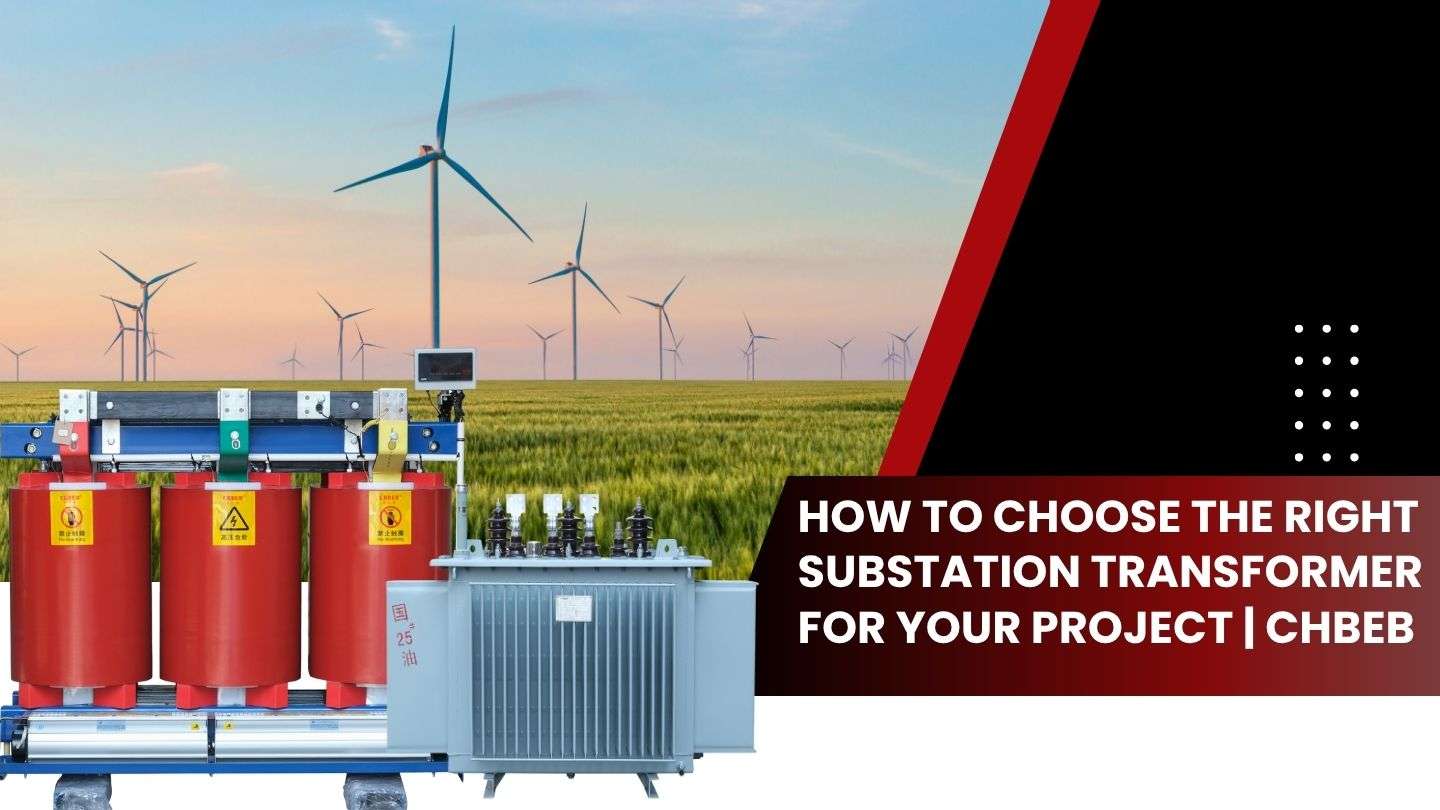
Substation Transformer Selection: The Ultimate Trade-Off Between Dry and Oil-Immersed Technologies | CHBEB
Introduction
Choosing the right transformer for a substation project is the most important decision that every project has to make.
Should you choose a transformer that is dry or one that is immersed in oil?
This choice affects not only performance but also safety, maintenance, and the cost of running the machine over the long term.
Engineers, EPC contractors, and investors may make decisions that last by knowing these trade-offs.
Performance & Safety: Cooling Efficiency, Capacity Limits, and Environmental Risks
Transformers at substations operate under high stress and must deliver exceptional reliability. The right technology for each application depends on cooling method, installation environment, and safety requirements.
Thermal Difference: Oil’s High-Capacity Advantage vs. Dry-Type’s Safety First
The key distinction between the two technologies lies in how they manage heat.
Oil-Immersed Transformers use mineral or ester-based oil for both cooling and insulation.
The oil circulates naturally (ONAN) or through pumps and fans (ONAF, OFAF) to maintain optimal temperature and thermal conductivity1.
Best for:
- Substations with a lot of power, up to 1,000 MVA
- Long-term use in industry or transmission
- Harsh conditions outside or near the coast
Pros:
- Better at getting rid of heat
- Ability to handle a lot of extra work
- Performance that stays stable over long periods of use
On the other hand, dry-type transformers use air or resin insulation technologies such as VPI (Vacuum Pressure Impregnation) or Cast Resin.
They are typically rated below 20 MVA, making them ideal for indoor or fire-sensitive environments.
Pros:
- No chance of oil leaking
- Very good fire safety
- Little upkeep
| Parameter | Oil-Immersed Transformer | Dry-Type Transformer |
|---|---|---|
| Cooling Medium | Mineral / Ester Oil | Air / Epoxy Resin |
| Typical Capacity | 5–1000 MVA | ≤20 MVA |
| Cooling Efficiency | High | Moderate |
| Fire Safety | Medium (improved with ester oil) | High |
| Maintenance | Regular oil checks | Minimal |
| Best Use Case | Outdoor substations, plants | Indoor or public areas |
👉In short, oil-immersed models have a higher power density, whereas dry-type units put safety and environmental compliance first.
Environmental Compliance: Noise, Fire Rating, and Installation Requirements
Modern substation designs must meet regulations for noise, fire, and the environment.
Noise:
Oil-immersed transformers are quieter because the oil absorbs vibrations in the core.
Step-lap silicon steel designs keep noise levels below 55 dB, meeting IEC 60076 standards2.
Dry-type transformers can be a little louder, but enclosures or vibration mounts can reduce the noise easily.
Fire safety:
Dry-type transformers are suitable for indoor use because they use Class F/H resin that puts out fires on its own.
Oil units now use synthetic ester oils, which are biodegradable and non-flammable, greatly reducing fire risks.
IRequirements for installation:
Oil-immersed: needs fire walls and containment pits to ensure safety.
Also requires ventilation for cooling, especially in confined spaces.
Typical applications:
- High-load outdoor sites → Oil-immersed
- Indoor, compact, or public areas → Dry-type
Insurance companies and regulators are increasingly favoring low-risk transformer installations, which is why dry-type units are becoming more common in modern infrastructure.
Economics: Balancing CAPEX and OPEX
Total ownership cost (TCO) — not just the initial price — is an important factor when choosing a substation transformer.
Oil-immersed transformers
- Lower initial cost (about 20–30% less for the same capacity)
- Require oil sampling, filtering, and replacement every 3–5 years
- Have slightly higher insurance and containment costs
Dry-Type Transformers
- Higher initial cost due to resin and insulation materials
- Minimal maintenance — only air filter cleaning and temperature checks
- No oil waste or disposal costs, ideal for areas with strict environmental regulations
| Cost Element | Oil-Immersed | Dry-Type |
|---|---|---|
| Purchase Price | Lower | Higher |
| Maintenance | Regular oil service | Minimal |
| Installation | Fire wall & oil pit | Simple indoor setup |
| Efficiency | Higher (liquid cooling) | Slightly lower |
| Lifetime | 30–40 years | 25–30 years |
✅ Conclusion: After 25 years, both have about the same TCO. Oil kinds are better in terms of capacity and cost, whereas dry types are better in terms of safety and ease of use.
Scenario-Based Selection: Matching Type to Application
Every project has its own set of rules and conditions.
Here’s how to choose the right transformer technology for your situation:
| Scenario | Recommended Type | Reason |
|---|---|---|
| Underground / Metro | Dry-Type | Fire-safe and compact |
| Data Center / Hospital | Dry-Type | Clean operation, low noise |
| Power Plant / Utility Substation | Oil-Immersed | High capacity and durability |
| Coastal or Outdoor Areas | Oil-Immersed (Ester Oil) | Weather-resistant and eco-safe |
| Urban Commercial Building | Dry-Type | Safe for people, zero leakage |
Ester oil-filled transformers are a new type of hybrid design that combines liquid cooling with fire-resistant performance. They are part of the global drive toward greener, higher-capacity systems.
🔎 Learn more about dry-type transformer selection and design in our in-depth Dry Type Transformer Guide 2025 — covering insulation types, VPI vs. cast resin, and IEC 60076 standards.
⚙️ CHBEB — Reliable Partner for Substation Transformer Solutions
For over 60 years, CHBEB has specialized in substation and distribution transformer engineering, offering both dry-type and oil-immersed solutions designed to meet global standards.
Why Choose CHBEB
- 🏭 Manufacturing Strength: Factories in Wenzhou and Nanjing, plus a logistics hub in Beijing, enabling fast production and delivery.
- 🔬 Engineering Expertise: All products tested under IEC 60076 and ISO 9001, ensuring reliability in every voltage class.
- 🌍 Global Reach: Trusted by utilities and EPCs in Russia, Southeast Asia, Africa, and Belt & Road countries.
- ⚡ Customized Design: From 50 kVA to 1000 MVA — tailored for your voltage, climate, and project needs.
- 📈 End-to-End Support: From selection consultation to installation guidance and certification documentation.
At CHBEB, we don’t just build transformers — we engineer reliability into every grid we power.
👉 Looking for a distribution transformer manufacturer that combines Chinese manufacturing strength with international standards?Contact CHBEB for a tailored solution or Download our full transformer catalog here.
🔍 Frequently Asked Questions (FAQ): Substation Transformer Selection
1. What’s the main difference between dry and oil-immersed substation transformers?
Oil-immersed transformers use liquid insulation for higher capacity and better heat dissipation.
Dry types rely on resin or air, offering fire safety and minimal maintenance — ideal for indoor or compact setups.
2. Which type is more suitable for high-voltage substations?
Oil-immersed transformers (ONAF/OFAF) handle up to 1000 MVA and are preferred for 110–500 kV systems.
Dry types are typically used below 35 kV.
3. Which transformer is safer for populated areas?
Dry-type transformers, thanks to their non-flammable insulation, are safer for metro, hospital, or commercial installations.
4. How long does each type last?
Oil-immersed: 30–40 years with proper oil monitoring and OLTC care.
Dry-type: 25–30 years with minimal servicing.
5. Can CHBEB help me choose the right substation transformer?
Absolutely. Our engineering team provides technical selection reports, thermal simulations, and custom designs for your project environment.
Conclusion
The choice between dry-type and oil-immersed transformers isn’t about which is superior — it’s about which fits your substation’s voltage, environment, and safety requirements.
Oil-immersed designs remain the benchmark for high-capacity and outdoor installations, providing excellent thermal efficiency and long service life. Dry-type transformers, on the other hand, are the preferred option for indoor, public, or fire-sensitive sites where safety and simplicity outweigh raw capacity.
For EPCs, utilities, and engineers, the smartest decision lies in evaluating total cost of ownership, installation context, and compliance standards — not just initial price.
When reliability, certification, and lifecycle performance truly matter, CHBEB’s engineering team stands ready to help you select, customize, and deliver substation transformers that keep your grid safe, efficient, and future-ready.
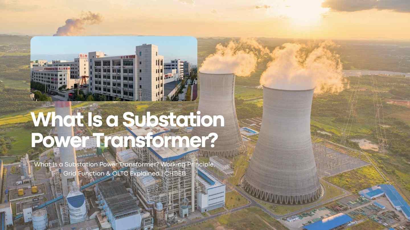
In-Depth Understanding: The Core Function and Grid Role of Substation Power Transformers
Introduction
A substation transformer is a silent workhorse that sits at the center of every power system. It makes sure that electricity flows smoothly from generation to consumers. These huge devices, on the other hand, can take enormous voltages, manage complicated cooling, and keep stability throughout whole regional networks. To understand how modern power systems stay reliable and efficient, you need to know what their roles are.
Fundamentals: Definition, Structure, and Dual Purpose
Before we get into how substations move power across the grid, it’s important to know what makes a substation power transformer different in terms of design and function.
Definition and Positioning: What Sets Them Apart from Distribution Units
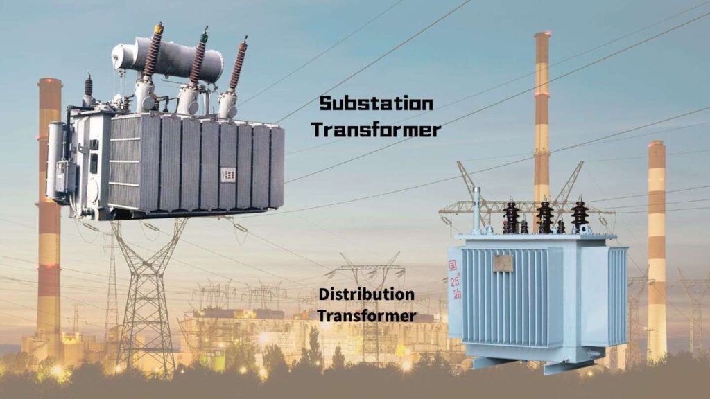
A substation power transformer is a large device that transfers electricity between voltage levels in the transmission system. It typically operates at 110–500 kV and handles over 100 MVA of power.
In contrast, distribution transformers reduce voltage for end users—usually below 35 kV—and serve localized loads such as homes or businesses.
| Type | Voltage Range | Capacity | Function |
|---|---|---|---|
| Substation Power Transformer | 110–500 kV | 60–1000 MVA | Interconnects generation and transmission systems |
| Distribution Transformer | ≤35 kV | 50–2500 kVA | Supplies local distribution networks |
The main distinction is where the grid is located. Substation transformers are the “main gatekeepers” for regional power transfer. They are located at generation, transmission, or primary substations.
Core Structure: Key Components and Complex Cooling Systems of Large Transformers
The design of a substation transformer is far more complicated than that of smaller dry-type or pad-mounted devices. Three main engineering systems affect how well it works:
- Active Part (Core and Windings)
The laminated magnetic core efficiently guides magnetic flux, while the copper or aluminum windings handle large currents with minimal loss. - System for Cooling
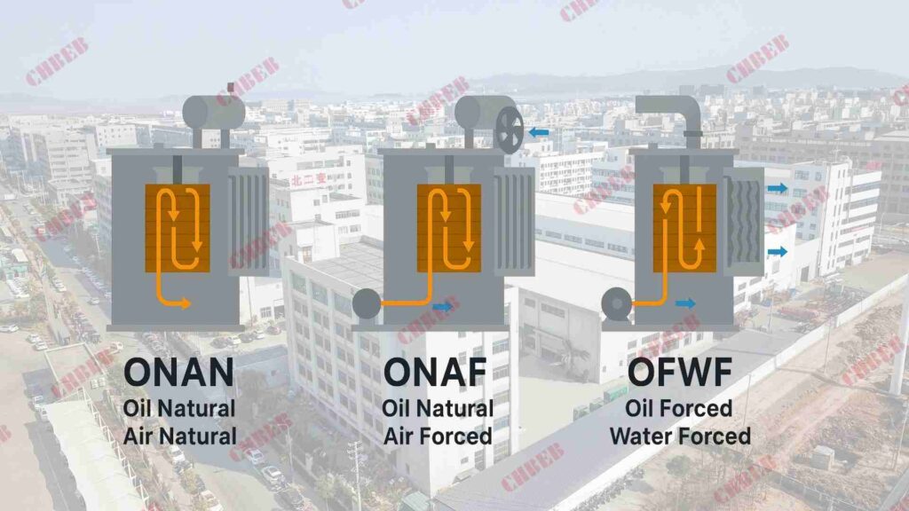
Large transformers generate significant heat. They rely on oil circulation and forced-air or water cooling, as defined by IEC and IEEE cooling codes such as:- ONAN (Oil Natural Air Natural): passive circulation for mild loads.
- ONAF (Oil Natural Air Forced): adds fans to enhance cooling efficiency.
- OFWF (Oil Forced Water Forced): used in very high-power transformers, including 500 kV grid units.
- Bushings and Tanks
The primary tank, which is usually made of welded steel, holds insulating oil and keeps its shape even when it gets hot. Bushings constructed of porcelain or composite materials safely move high-voltage wires in and out of the unit.
These systems work together to create a balance of electrical efficiency, mechanical strength, and thermal regulation.
The Grid Nexus: How Substation Transformers Ensure Efficient Power Transfer
Substation transformers are the main link between the generation, transmission, and distribution layers of the electrical grid. They not only change voltage, but also maintain power flow, reduce losses, and stabilize voltage levels as loads fluctuate.
The Two Main Tasks in the Grid: Step-Up and Step-Down on the Energy Journey
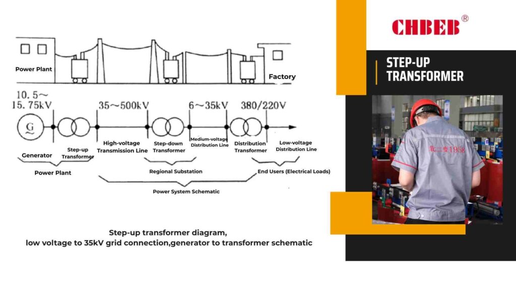
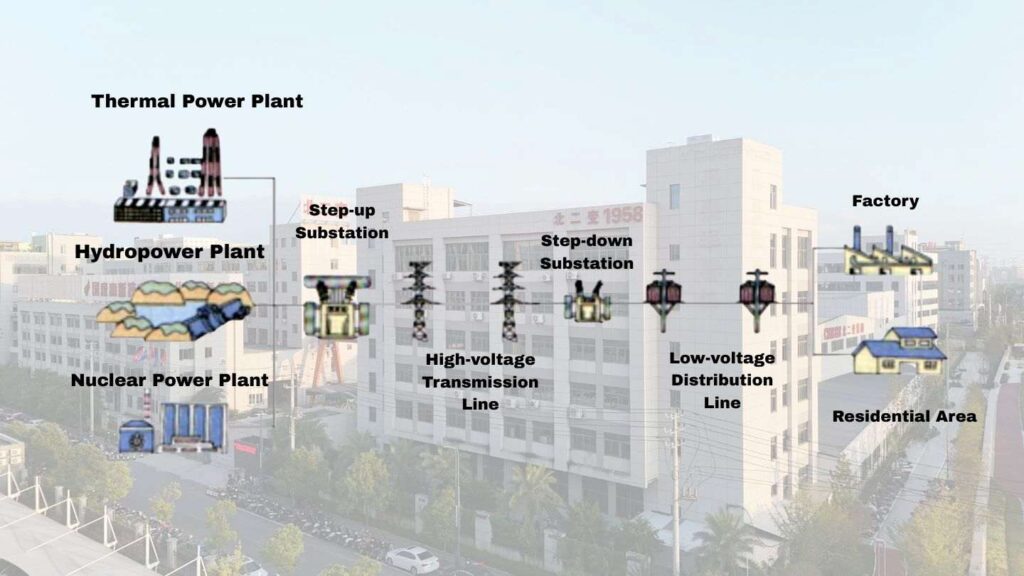
Electricity is generated at medium voltages (typically 11–25 kV). Power plants use step-up transformers to increase voltage to hundreds of kilovolts, significantly reducing current and line losses, making long-distance transmission more efficient.
At the receiving end, step-down transformers in major substations lower the voltage again for safe and efficient distribution to businesses and regional networks.
This two-way procedure shows how electrical energy moves:
- Step-Up Stage: increases voltage to make transmission more efficient.
- Stage of Transmission: sends high-voltage power over great distances.
- Step-Down Stage: lowers the voltage so it can be safely distributed locally.
Power grids would lose a lot of money and voltage would drop over even short distances if there were no substation transformers.
| Function | Typical Voltage | Application |
|---|---|---|
| Step-Up Transformer | 11 → 220–500 kV | Power generation stations |
| Step-Down Transformer | 220 → 35–110 kV | Regional or primary substations |
Grid Stability: The Role and Importance of the On-Load Tap Changer (OLTC)
In real grids, voltage changes constantly due to variations in load, temperature, and distance. Substation transformers use an On-Load Tap Changer (OLTC) to maintain a stable supply by adjusting the transformer’s turns ratio without interrupting operation.
OLTCs monitor output voltage in real time and automatically switch taps to raise or lower voltage within a small range (typically ±10%). This ensures that industrial facilities and distribution networks receive a consistent power supply, even under fluctuating demand.
Modern OLTCs are equipped with motor drives, electronic controllers, and SCADA connectivity, enabling remote operation and predictive maintenance.
A well-maintained tap changer can perform over 500,000 switching operations during its service life.
Maintenance and Challenges: Ensuring Long-Term Reliability
Substation transformers are designed to endure for decades, but they need to be monitored all the time, have preventive maintenance done, and follow international standards to stay reliable.
Reliability Paramount: Maintenance Requirements and Lifespan Considerations
1. Oil Monitoring and Filtration
Transformer oil serves as both an insulator and coolant. Regular testing for moisture, acidity, and dielectric strength is vital. Dissolved gas analysis (DGA) identifies early signs of overheating or insulation breakdown.
2. Thermal Management
Infrared thermography detects hot spots caused by load imbalance or poor connections. Cooling fans and pumps require periodic cleaning and bearing inspection to ensure efficiency.
3. Electrical Testing
Routine tests include winding resistance, turns ratio, insulation resistance (IR), and power factor measurements. These ensure electrical integrity and prevent catastrophic faults.
4. Mechanical Integrity
Vibration monitoring helps detect loose core clamps or tank deformation. Foundation bolts and bushing seals are checked to prevent oil leakage and mechanical stress.
5. Digitalization and Remote Diagnostics
Smart monitoring systems equipped with IoT sensors continuously track oil temperature, load current, and tap-changer status. Cloud-based analytics can predict failures months in advance, reducing downtime and maintenance cost.
With proper operation and maintenance, substation transformers can achieve a service life of 30–40 years, though aging insulation and mechanical fatigue remain key challenges.
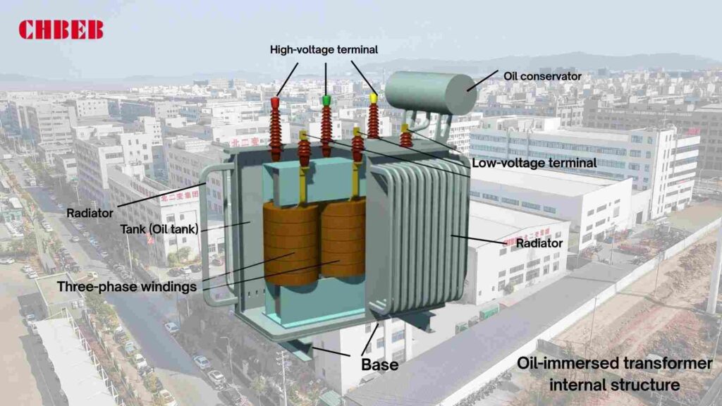
🔍 Frequently Asked Questions (FAQ): Substation Power Transformers
1. What’s the difference between substation transformers and distribution transformers?
Substation transformers operate at high voltages (110–500 kV) and handle regional power transfer between generation and transmission networks.
Distribution transformers, on the other hand, work below 35 kV and deliver power directly to residential, commercial, or industrial users.
In simple terms — substation transformers move electricity across regions, while distribution transformers deliver it to end consumers.
2. How does a substation transformer work?
It operates based on Faraday’s Law of Electromagnetic Induction1. Alternating current in the primary winding generates a changing magnetic field in the core, inducing voltage in the secondary winding.
Step-up transformers raise voltage for transmission efficiency, while step-down units reduce voltage for safe regional distribution.
3. Why are substation transformers so large?
Because they handle massive voltage and current levels, often reaching hundreds of megawatts.
Their size allows for stronger magnetic cores, thicker windings, and oil-based cooling systems — all necessary to manage thermal stress, magnetic flux, and insulation safely and efficiently.
4. Can a substation transformer step voltage up as well as down?
Yes. Step-up transformers at generation plants increase voltage from 11–25 kV to 220–500 kV for long-distance transmission.
Step-down transformers at primary substations then reduce it back to 35–110 kV, making power suitable for industrial or regional use.
This bidirectional capability ensures smooth voltage control across every stage of the grid.
5. How long does a substation transformer last?
With proper oil quality analysis, thermal management, and preventive maintenance, a substation transformer can operate reliably for 30–40 years.
Modern units equipped with digital monitoring and OLTC diagnostics can achieve even longer service life by predicting and preventing potential failures.
6. What is the role of transformer oil?
Transformer oil acts as both a coolant and electrical insulator.
It transfers heat from the windings to the radiators and prevents arcing or flashover between energized components.
Routine testing for moisture content, gas levels, and dielectric strength ensures stable insulation performance over decades of use.
7. What is an OLTC (On-Load Tap Changer)?
An OLTC automatically adjusts the transformer’s turns ratio while energized, maintaining constant output voltage despite load variations.
It fine-tunes voltage within a typical ±10% range, stabilizing grid performance and ensuring power reliability for industries and utilities alike.
In modern systems, OLTCs integrate motor drives, electronic control, and remote SCADA monitoring for predictive maintenance and operational accuracy.
⚙️ CHBEB — Reliable Partner for Substation and Power Transformer Solutions
For over 60 years, CHBEB has specialized in the design, manufacturing, and testing of high-voltage and distribution-grade transformers that power cities, industries, and national grids worldwide.
What We Deliver
High-Voltage Expertise
From 35 kV to 500 kV substation power transformers engineered to IEC 600762 and GB standards, ensuring precision, durability, and efficiency.
Proven Reliability
A certified supplier to the State Grid Corporation of China, CHBEB maintains a spotless record of safety and long-term operational stability across thousands of projects.
Engineering Integration
Advanced oil-immersed and dry-type designs featuring smart OLTC control, digital monitoring, and low-loss core technology for optimal grid performance.
Global Presence
Serving Russia, Southeast Asia, Africa, and Belt and Road countries, CHBEB adapts every transformer to meet regional grid conditions, climates, and standards.
Fast Delivery & Full Certification
With factories in Wenzhou and Nanjing and a logistics hub in Beijing, CHBEB ensures rapid fulfillment and provides IEC/CE documentation for seamless international approval.
At CHBEB, we don’t just build transformers — we build confidence into every grid we serve.
Our mission is simple: to deliver high-efficiency, low-loss, and globally compliant power solutions that keep the world’s substations running safely, reliably, and for decades to come.
👉 Looking for a distribution transformer manufacturer that combines Chinese manufacturing strength with international standards?Contact CHBEB for a tailored solution or Download our full transformer catalog here.
Conclusion
Substation power transformers are more than heavy electrical machines — they are the guardians of grid stability and efficiency. Through decades of engineering evolution, they’ve learned to balance extreme voltage, heat, and demand while silently securing energy for entire regions.
From the precise operation of an On-Load Tap Changer (OLTC) to the chemistry of transformer oil, every detail defines reliability. That’s why proper design, material control, and predictive maintenance matter more than ever as grids evolve toward renewable and smart automation.
For engineers and utilities, the takeaway is clear: investing in a well-engineered, certified power transformer is not just buying equipment — it’s securing decades of safety and performance for your network and your customers.

Introduction
When a transformer enclosure fails, it’s never just a box issue — it’s a performance, safety, and certification problem. A trusted OEM/ODM partner ensures your enclosure protects, cools, and complies with every standard, adding real engineering value from CAD design to global certification.
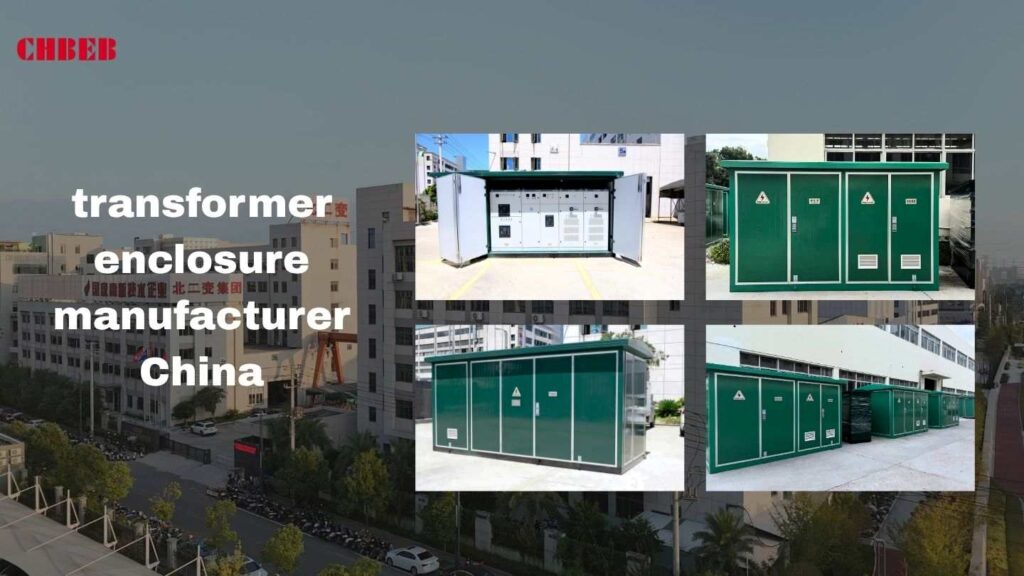
Design Driven by Demand: The Core Value and Engineering Elements of OEM/ODM
Every project starts with a purpose — and a demand. Whether it’s for desert heat, coastal humidity, or Compact substations and custom transformer enclosures are made to fit the rules and conditions of the location.
What is OEM/ODM and how can it help you save money and time when bringing a product to market?
OEM (Original Equipment Manufacturer) and ODM (Original Design Manufacturer) models are key parts of the transformer supply chain. OEM focuses on making things to client specifications, while ODM adds engineering and design skills to create new solutions from start.
For transformer firms, this two-part service means:
- Shared tools and modular engineering help keep costs down.
- Ready compliance documents help you get to market faster.
- Scaling up from prototype to mass production is easy.
- Standards stay consistent around the world.
OEM/ODM is more than outsourcing — it brings technical knowledge into your supply chain to ensure every enclosure fits your brand and certification goals.
Core Engineering: Balancing Heat Dissipation, IP Protection, and Corrosion Resistance
Custom enclosures are more than just metal shells. They are designed systems that control airflow, heat, and stress on the environment.
Three main design problems determine how well an enclosure works:

- Getting rid of heat
Transformers always make heat. Engineers employ CFD (Computational Fluid Dynamics) models to improve the design of vents, the flow of air inside, and the routes for natural and forced cooling. A good thermal balance keeps the winding from breaking down and keeps the electrical efficiency steady. - Protection for IP
IP (Ingress Protection)1 ratings tell you how well the case protects against dust, rain, and accidental touch. Outdoor units usually have an IP54 to IP65 rating. They use waterproof gaskets and permeable membranes to keep condensation from forming while still letting pressure equalize. - Resistance to Corrosion
Hot-dip galvanizing, zinc-aluminum plating, or marine-grade powder coating are all examples of anti-corrosive coatings that are needed in coastal or chemical environments. ASTM B117 salt-spray testing checks the longevity of a coating after years of exposure.
A well-planned enclosure isn’t just created; it’s meant to last by balancing electrical safety, environmental durability, and appearance.
Manufacturing and Compliance: Key Steps for Quality and Global Market Access
Each step of the fabrication process, from design validation to powder coating, affects how effectively the finished product works in the field and how well it passes certification.

Fabrication Process: From Material Selection to Powder Coating Technology
1. Choosing the right materials
Depending on the project’s needs, materials usually include cold-rolled steel, aluminum, or stainless steel (304/316).
2. Laser cutting and CNC bending
Precision manufacturing reduces gaps, distortion, and sharp edges to keep IP and NEMA ratings consistent.
3. Assembly and welding
MIG/TIG welding or rivet bonding ensures clean seams and strong structure. All joints are inspected for cracks or holes before surface treatment.
4. Surface preparation and powder coating
Surfaces are cleaned, sandblasted, and chemically treated (phosphate or chromate). Powder coating is then cured at 180–200 °C to create a durable and color-stable finish.
5. Final check and testing
Each enclosure is tested for size, door alignment, IP water spray, and grounding continuity.
The end result is a strong, rust-proof container that looks good and performs well.
Quality Assurance: UL, NEMA Ratings, and the “First-Time Pass” Compliance Strategy
Global markets demand conformity with several certification systems:
| Region | Standard | Key Requirements |
|---|---|---|
| North America | UL 50 / NEMA 250 | Enclosure construction, gasket integrity, corrosion resistance |
| Europe | IEC 62208 / EN 60529 | Electrical insulation, ingress protection, dielectric strength |
| Middle East & Asia | GCC, SASO, GB Standards | Temperature rise limits, earthing reliability, mechanical strength |
Getting a “First-Time Pass” rating on a certification test shows that design control is strong. This means:
- Pre-certification testing (salt spray, impact, dielectric)
- Strict documentation control for materials and processes
- Continuous feedback between manufacturing and QC teams for improvement
OEM/ODM providers may deliver enclosures ready for UL, CE, or IEC labeling, cutting weeks off client approval time.
Partnership and Delivery: Custom Project Workflow, Lead Times, and Quick Q&A

Strong relationships convert complicated technical jobs into solutions that can be predicted and scaled. Communication, accuracy, and clear goals are key to the success of custom enclosure manufacture.
The Custom Project Workflow: Six Critical Stages from Blueprint to Final Delivery
- Design Input & Feasibility Review – The client provides drawings or performance targets. Engineers verify mechanical fit, IP class, cooling requirements, and compliance feasibility.
- 3D CAD Modeling & Simulation – Detailed CAD designs are created with airflow and strength simulations. Prototypes may be 3D-printed for dimensional validation.
- Prototype Fabrication & Testing – One or two units are built to test fit, finish, and performance under IP or temperature-rise conditions.
- Client Approval & Mass Production – After approval, batch manufacturing begins under standardized work instructions and inspection checkpoints.
- Final QC & Certification Support – Each unit is inspected according to UL/NEMA or IEC standards, and compliance reports are generated for client submission.
- Packaging & Delivery – Enclosures are packaged with vibration protection and moisture-proof wrapping, shipped domestically or exported with HS coding and certificate of origin.
Lead Time
- Standard prototypes: 7–15 days
- Batch production: 25–40 days (depending on quantity and coating process)
- Export logistics: 10–20 days (sea or air freight)
Project Delivery Q&A
Q1: Can you match my existing transformer design?
Yes. OEM services can reproduce enclosures directly from your CAD drawings or samples while maintaining IP, NEMA, and certification consistency.
Q2: Do you provide certification support?
All products can be built and pre-tested for UL, CE, and IEC standards, complete with inspection and traceability reports to streamline client approval.
Q3: What’s the minimum order quantity?
Typically 1–5 units for prototype, scalable to full production batches once the design is approved.
⚙️ CHBEB — Reliable Partner for OEM/ODM Transformer Enclosure Solutions
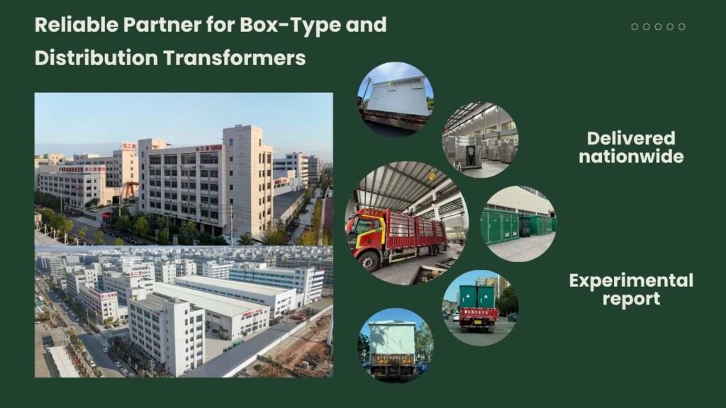
Behind every compliant, high-performance transformer enclosure is not just steel and paint — it’s engineering precision and manufacturing discipline.
With over 60 years of transformer expertise, CHBEB provides full-spectrum OEM/ODM services from CAD design to certification-ready mass production.
What Makes CHBEB Different
- Engineering Integration: In-house R&D runs CFD airflow simulations, structural analysis, and pre-certification testing to ensure long-term performance under all IP/NEMA conditions.
- Smart Manufacturing: CNC cutting, laser welding, and automated powder-coating lines deliver micron-level accuracy and repeatable quality.
- Global Compliance: Products are designed to meet UL 50, NEMA 250, IEC 62208, and EN 60529 standards, supported by full material traceability and documentation.
- Durability That Lasts: Marine-grade coatings, 316 stainless or galvanized steel options, and salt-spray testing guarantee reliability in coastal or industrial environments.
- Worldwide Delivery: With factories in Wenzhou and Nanjing, plus a logistics center in Beijing, CHBEB ensures fast OEM fulfillment and exports to over 30 countries across Asia, Africa, Russia, and the Middle East.
From prototype to production, CHBEB helps transformer manufacturers, EPC contractors, and utilities turn complex enclosure requirements into certified, globally accepted products — built to perform, built to last.
👉 Looking for a partner who combines Chinese manufacturing strength with global engineering standards? Contact CHBEB for a tailored technical proposal or download our full catalog today.
Frequently Asked Questions (FAQ): Custom Transformer Enclosures
Q1. OEM vs. ODM2 enclosures — what’s the real difference?
OEM: You provide drawings and specs — we manufacture exactly to print.
ODM: You provide functional goals — we co-engineer structure, cooling, and compliance.
Tip: Finished design? Go OEM. Need technical input and testing? Choose ODM.
Q2. How long does a custom enclosure take?
Prototype: 7–15 days
Batch production: 25–40 days
Export: 10–20 days
Locking coating and gasket specs early saves time and ensures fast certification.
Q3. Which coating is most durable — powder or liquid?
Powder coating forms a tougher, UV-resistant finish with minimal VOC emissions.
Liquid paint suits complex shapes or special finishes.
For coastal sites, combine a zinc-rich primer and polyester powder topcoat, validated through ASTM B117 salt-spray testing.
Q4. How to ensure UL compliance?
Design according to UL 50 / UL 50E and NEMA 250 construction rules.
We perform dielectric, corrosion, and impact tests, and provide pre-certification data to achieve first-time pass results.
Q5. What’s the best material for outdoor enclosures?
Hot-dip galvanized steel for inland areas.
Aluminum (5052/6061) for lightweight structures.
Stainless 316 for coastal or chemical environments.
All coatings validated through salt-spray and adhesion testing.
Q6. IP vs. NEMA — what’s the difference?
IP ratings (IEC 60529) measure dust and water ingress.
NEMA 250 covers ingress plus corrosion and mechanical strength.
Approximate guide: NEMA 3R ≈ IP24, NEMA 4 ≈ IP66, NEMA 4X ≈ IP66 with corrosion protection.
Q7. Can you produce directly from my CAD drawings?
Yes. We accept STEP/IGES/DWG/DXF files, review for DFM improvements (bend reliefs, airflow, gasket compression), and return updated GA drawings before fabrication.
Conclusion
Transformer enclosures aren’t just sheet metal—they are thermal, ingress, corrosion, and compliance systems that determine uptime and certification outcomes. If your target market requires UL/NEMA or IEC/IP performance, the path to “first-time pass” is clear: define the environment, rating, and lead time; share CAD or targets; then validate via CFD, material/coating selection, and pre-cert testing.
Whether you choose OEM (build-to-print) or ODM (co-engineered), pick a partner who proves these three things up front: (1) a documented compliance plan for UL 50 / NEMA 250 or IEC 62208 / EN 60529, (2) process capability from laser/CNC to marine-grade finishing, and (3) predictable lead times from prototype (7–15 days) to batch (25–40 days). That is how enclosure projects launch on schedule, pass certification the first time, and remain reliable in desert heat or coastal humidity.
Have drawings? We can manufacture to print. Have performance goals? We can co-design the airflow, gasket stack-up, and coatings, then supply the pre-cert data pack you’ll need for UL/CE submission—so your enclosure is ready to ship, install, and perform from day one.

Introduction
The transformer substation1, a modest, silent green box that most people walk by every day, is important to every community. It could look normal, but within is the system that keeps your devices charged and your lights on. Let’s open this “green box” and find out how it safely and quietly fuels your town.
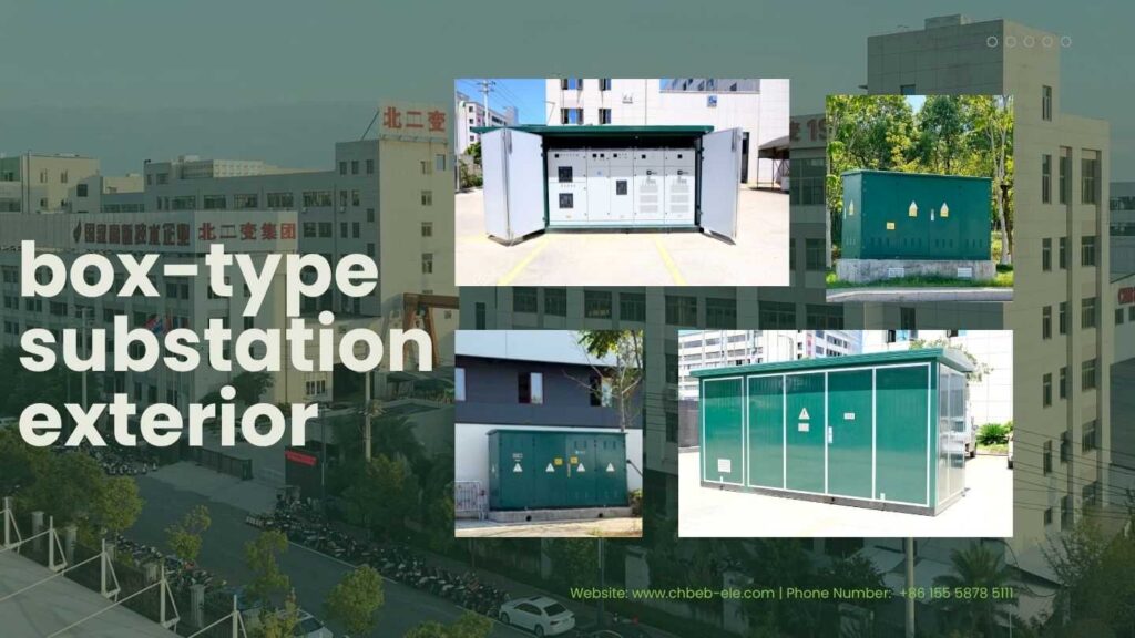
Core Function: The Working Principle and Integrated Structure
Transformer substations connect the high-voltage grid to local customers in modern distribution networks. These units are small, smart, and made to change, protect, and control power all in one box.
Role and Definition: The “Voltage Faucet” of the Distribution Grid
Think of electricity as water that is under pressure. It travels well over great distances on high-voltage lines, but before it gets to homes and businesses, the pressure must to drop to a level that is safe to use.
The transformer substation does this task. It lowers the voltage from 10 to 35 kV to 0.4 kV, making it safe to use every day.
Usually, each box-type substation has:
- Power transformer (to change the voltage)
- High-voltage switchgear (for safety and control)
- Low-voltage distribution cabinet (for lines that go out)
- Auxiliary circuits for lighting, measuring, and watching
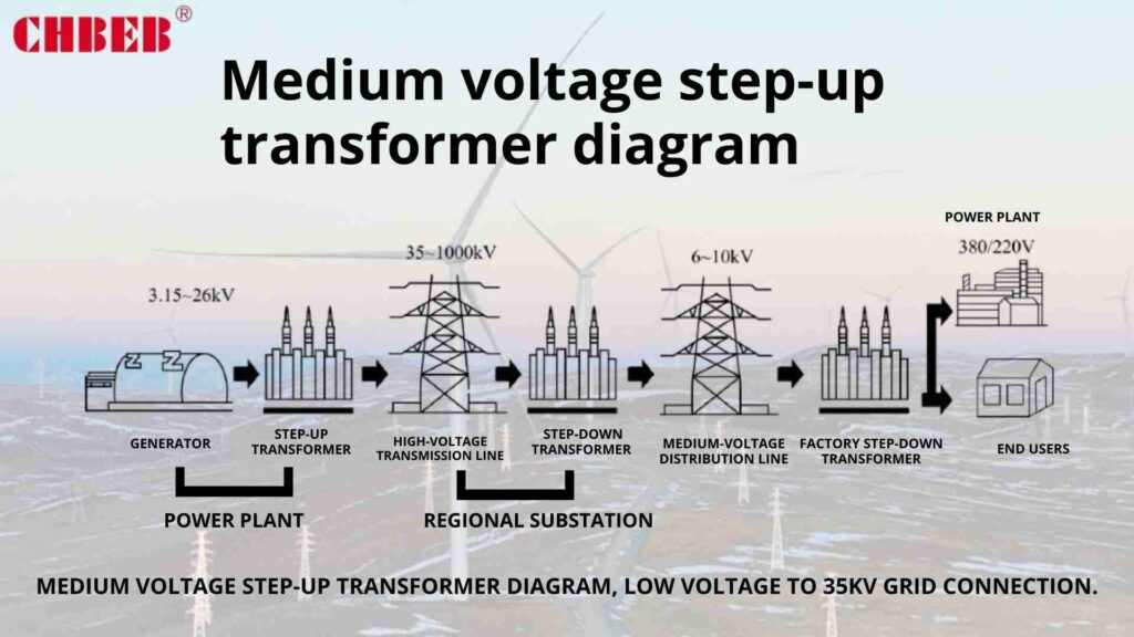
This combination turns it into a small power distribution center that can automatically find and fix problems and keep the power supply stable in real time.
Anatomy Inside: The Integrated Design of the Transformer and Switchgear
The inside of the green shell is meticulously designed for both safety and performance.
- There is an oil-immersed or dry-type transformer in the transformer compartment that lowers the voltage.
- The HV and LV switchgear sections have breakers, fuses, and protection relays that govern the circuits that come in and go out.
- The busbars and wires connect each system through channels that are insulated and fireproof.
Most modern box-type substations are put together in a factory, tested, and sealed against dust and rain (IP54 or higher). This design ensures quick installation, minimal maintenance, and a long service life, especially in tough places like deserts or coastal areas.
Community Safety: Addressing Concerns About Noise, EMF, and Physical Risk
People often worry about transformer substations that are close to homes. Will they be loud, give off radiation, or be dangerous if you touch them? In fact, these boxes have a number of safety features that make them as safe as any other piece of public utility equipment.

“Three Lines of Defense” Against Electric Shock and Fire
- Separation of electricity
Metal barriers and grounding systems completely surround each chamber. Even maintenance staff can’t touch live parts without following the right steps. - Protection Against Overcurrent and Fault
When there is too much electricity, a short circuit, or a problem with the insulation, circuit breakers and relays immediately turn off the power. The time it takes to respond is measured in milliseconds. - Preventing fires and keeping structures safe
Self-extinguishing insulation is used in dry-type transformers. Fire-resistant fluids fill oil-type systems, and pressure-relief valves keep them safe.The enclosure is built of galvanized steel or aluminum alloy and is painted with paint that doesn’t rust. It also has ventilation grilles to keep heat from building up.
These layers work together to make a “three-line defense system” that protects both the equipment and the people who live nearby.
Scientific Facts: Understanding Electromagnetic Fields (EMF) and Safe Distance
All electrical devices, from hair dryers to phone chargers, give off electromagnetic fields (EMF) as a natural consequence. Transformers make EMFs, but only in extremely small amounts.
International standards like WHO, IEEE, and ICNIRP2, along with scientific studies, show that EMF exposure near distribution transformers is well below acceptable levels.
The international exposure limit for the public is 100 µT, however typical EMF values measured 1 meter from a box substation range from 0.2 to 3 µT (microteslas).
Most countries say that substations should be a few meters away from buildings, not because of the risk of radiation, but for maintenance access and ventilation. To sum up, you can walk, live, or park next to one without worrying.
Practical Know-How: Types, Maintenance, and Common Issues
Knowing a few basic things about how substations are built and kept up helps people in the area appreciate how quiet and reliable they are.
Design Types: American vs. European Box Style and the Humming Sound Explained
There are two main design philosophies that box-type substations usually follow:
- American Style (Transformer on a Pad)
- An oil-filled tank holds both a transformer and switchgear.
- Small size and easy-to-understand design.
- Used a lot in North America and places with strict safety rules.
- European Style (Small, Prebuilt Substation)
- Separate areas for high voltage (HV), transformer, and low voltage (LV) systems.
- Stresses the importance of modularity and ease of maintenance.
- Common in cities in China, the Middle East, and Europe.
People sometimes hear a “humming sound,” but it’s not an electrical risk. It’s just the iron core of the transformer vibrating naturally under changing magnetic flux. Engineers use step-lap silicon-steel core cutting, vacuum varnishing, and elastic mounts to reduce the noise.
It’s about as loud as a quiet conversation (50–55 dB), and you can’t hear it more than a few meters away.
Common Problems and How to Fix Them
Box substations are made to work without anyone being there, but they nevertheless are checked on a regular basis:
- Check for rust or loose connectors by looking at them.
- Cleaning the filters in the ventilation system and checking the grounding continuity.
- Using remote SCADA systems to keep an eye on load balance and temperature sensors.
Scheduled maintenance can help you avoid common problems like worn-out insulation or cables that have been used too often. Many new units also have IoT sensors that transmit alarms before problems happen. This keeps the power in your community consistent all day and night.
⚙️ CHBEB — Reliable Partner for Box-Type and Distribution Transformers
Behind every “green box” that powers homes and communities, there are engineers, factories, and suppliers who make reliability possible. CHBEB is one of China’s trusted manufacturers of distribution and box-type substations, combining over 60 years of transformer expertise with modern production and testing technology.
From Wenzhou to Nanjing, CHBEB operates three manufacturing bases and a logistics office in Beijing, ensuring both strong production capacity and rapid nationwide delivery. Every transformer and substation is tested under IEC 60076 and IEC 62271-202 standards, guaranteeing low loss, safety, and long-term performance even in coastal or high-humidity regions.
What Makes CHBEB Stand Out
- Complete Range: From 50 kVA to 3150 kVA dry-type and oil-immersed distribution transformers, as well as integrated box-type substations.
- Quality Without Compromise: 100 % new copper, high-grade silicon steel, and epoxy insulation tested to Class F/H fire ratings.
- Proven Reliability: Certified supplier for the State Grid Corporation of China, maintaining a flawless record of safety and stability.
- Fast Delivery: Standard units ready for dispatch within 24 hours; customized solutions within 2–3 weeks.
- Global Reach: Exported to Russia, Southeast Asia, Africa, and Belt and Road countries, supporting EPC contractors and utilities worldwide.
Whether it’s a neighborhood upgrade or an industrial substation project, CHBEB delivers tested quality, certified performance, and long-term engineering reliability — ensuring every green box operates safely and efficiently.
👉 Looking for a distribution transformer manufacturer that combines Chinese manufacturing strength with international standards?Contact CHBEB for a tailored solution or Download our full transformer catalog here.
🔍 Frequently Asked Questions (FAQ)
1. What’s the purpose of those green boxes on the street?
They’re compact transformer substations that step high-voltage electricity (10–35 kV) down to 0.4 kV for local use. Inside, they contain transformers, switchgear, and control panels — essentially a full mini power center hidden in plain sight.
2. Do these boxes give off radiation?
No. The electromagnetic fields (EMF) around a box-type substation are extremely low — far below international safety limits set by WHO and ICNIRP. Standing near one is as safe as using household electronics.
3. How far should I stay from a transformer box?
There’s no danger zone. The few meters of distance often seen around these boxes are for maintenance access and ventilation, not for radiation safety.
4. Why does it make a humming sound?
That gentle hum is simply the vibration of the magnetic core when alternating current passes through. It’s normal, harmless, and usually kept below 55 dB — similar to a quiet conversation.
5. Is it oil-immersed or dry-type inside?
Both types exist. Urban and residential areas mostly use dry-type transformers for fire safety, while oil-immersed units are common in outdoor or large-capacity applications.
6. Can I get an electric shock if I touch the green box?
No — all external parts are grounded and sealed. Live conductors are completely enclosed in metal compartments. Even maintenance crews follow strict lockout procedures before opening.
7. Can these boxes catch fire?
Extremely rare. Dry-type units use self-extinguishing insulation, while oil-immersed designs use fire-resistant fluids. Each enclosure is made from galvanized or aluminum alloy with pressure-relief and ventilation systems to prevent ignition.
Conclusion
The green transformer substation you pass every day is more than a simple utility box—it’s a compact, intelligent power system that quietly supports modern life. Inside, layers of engineering precision ensure electricity is delivered safely, efficiently, and sustainably to every home and business.
Whether built as a dry-type or oil-immersed system, each box-type substation reflects decades of progress in insulation, protection, and smart monitoring—turning complex power conversion into everyday convenience.
So next time you see that silent green box on your street, remember: it’s not just equipment. It’s the unseen bridge between high-voltage grids and the comfort of your daily life—a quiet symbol of how engineering keeps communities connected and safe.

Introduction
The world’s energy infrastructure is getting smarter, greener, and safer. Dry-type systems that use modern materials, smart cooling, and safety that doesn’t leak are taking the role of traditional oil-filled transformers. This article talks about how current dry-type transformers work and why they are the best choice for next-generation power networks.
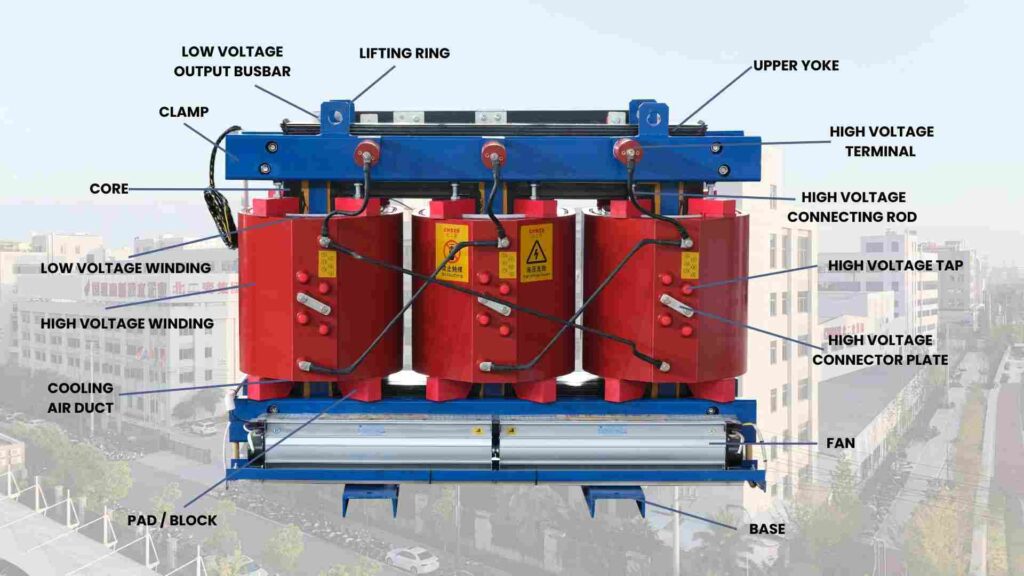
Core Mechanism: The Science of Oil-Free Insulation and Induction
Modern dry-type transformers don’t need oil to cool or insulate them anymore. Instead, they use air circulation, solid insulation, and computerized design tools to get the same magnetic induction process, but with far better safety and environmental performance.
Basic Idea: How Electromagnetic Induction Works in Dry Type Units
These transformers still work according to Faraday’s Law of Electromagnetic Induction1, which says that voltage changes as magnetic flux changes. But what makes this new is how engineers now manage and improve that flow.
Designers can use 3D finite element magnetic simulations to make small changes to the shape of silicon-steel laminations to reduce hysteresis and eddy current losses. Intelligent monitoring sensors keep an eye on temperature and magnetic performance in real time. This lets the transformer change the speed of the fan and the cooling cycles on its own.
This real-time feedback loop cuts down on energy loss by up to 15% in smart grids and renewable energy systems compared to standard dry-type devices.
The Insulation Secret: Comparing VPI vs. Cast Resin Winding Technologies

Both VPI and Cast Resin are still the major parts of dry-type insulation, however new eco-materials are changing them.
VPI (Vacuum Pressure Impregnation): Solvent varnishes have been replaced with advanced water-based or low-VOC resins, which makes production cleaner and more environmentally friendly. This means less pollution and longer insulation life.
Cast Resin (Epoxy Encapsulated): Manufacturers now utilize epoxy systems loaded with nano-silica that have better thermal conductivity, which makes them better at heat dissipation and mechanical strength. Some also apply graphene coatings to improve dielectric performance and resistance to partial discharge.
These modifications turn what used to be a simple insulation technique into a protection system designed to last, even under extreme humidity or vibration.
| Feature | Traditional Design | Next-Generation Improvement |
|---|---|---|
| Resin Material | Standard epoxy | Nano-filled, eco-friendly epoxy |
| Dielectric Strength | Stable | Enhanced (graphene coating) |
| Environmental Impact | Medium | Low (VOC-free varnish) |
| Thermal Conductivity | Moderate | High |
| Lifecycle | 20 years | 30+ years |
Engineering Excellence: Design Strategies for Fire Safety, Efficiency, and Low Maintenance
These days, dry-type transformers are built with long-term performance and sustainability in mind. Modern engineering combines fire safety, efficiency, and digital monitoring into one system.
Thermal Management: ONAN and ONAF Systems for Heat Dissipation
The old ONAN and ONAF cooling methods have become smart thermal management systems.
ONAN (Air-Natural): CFD (Computational Fluid Dynamics) is used to simulate airflow channels so that cooling is even without fans.
ONAF (Air-Forced): Smart fans only turn on when temperature sensors detect a certain level, which saves energy.
AI-based temperature controllers analyze historical data to predict when cooling is needed. This makes fan cycles more efficient and extends bearing life. The end result is quieter, more efficient, and longer-lasting transformers that meet the IEC 60076-112 thermal performance standards.
Value Conversion: Engineering the Fire-Proof, Eco-Friendly, and Maintenance-Free Advantages
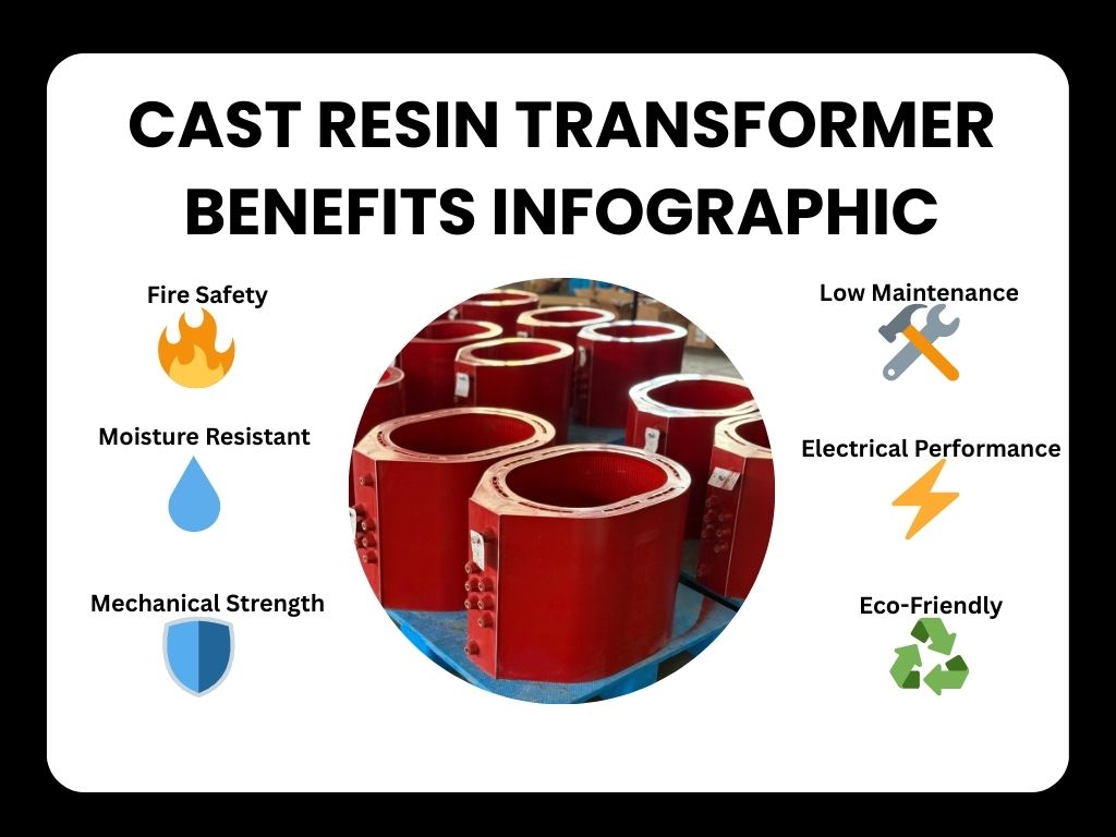
Today’s dry-type transformers are an example of the move toward designs that are safe against fire and good for the environment.
- Fire Safety: Class F or H fire classifications say that solid epoxy insulation and self-extinguishing materials lower the possibility of oil catching fire.
- Environmental Sustainability: Oil-free operation eliminates leaks and soil contamination, and insulation systems that may be recycled follow ISO 14001 standards.
- Energy Efficiency: Amorphous or nano-crystalline steel, step-lap joints, and precision core cutting cut no-load losses by 20–30%.
- No need for oil means no need for filter, sampling, or containment pits. Just clean the air and scan it using infrared thermal imaging every once in a while.
Dry-type units are now a key part of sustainable energy systems since they are changing from traditional insulation to smart eco-design.
Selection & Limitations: When and Where to Choose Dry Type Units
Dry-type transformers are not universal, even if they have some benefits. Their real worth comes from specific applications where safety, sustainability, and reliability are more important than high capacity.
Application Positioning: The Best Way to Choose Between Oil-Immersed Transformers and Other Options
When to use dry-type transformers:
- The installation site is within or in a busy city area, like a hospital, subway station, or commercial tower.
- There are tight rules on fire safety and environmental protection.
- The project needs IoT-based monitoring or integration with smart-grid technology.
- You want equipment that lasts long, needs little maintenance, and has a low carbon footprint.
Continue using oil-immersed units when:
- The transformer’s voltage rating is more than 35 kV or its capacity is higher than 5000 kVA.
- The place where the installation will take place is completely outside, has natural ventilation, and is not very likely to catch fire.
- The most important thing is the initial CAPEX, and maintenance crews are always on hand.
| Comparison Aspect | Modern Dry Type | Oil-Immersed |
|---|---|---|
| Fire Safety | Self-extinguishing | Requires fire barriers |
| Monitoring | IoT & thermal sensors | Manual inspection |
| Eco Impact | Zero leakage | Oil waste risk |
| Efficiency | High (IEC Tier 2) | Medium |
| Typical Use | Smart grids, renewables, buildings | High-capacity substations |
Engineers can make sure that modern infrastructure meets its sustainability and digitalization goals by making sure that these design and operational variances fit the needs of the project.
⚙️ CHBEB — Reliable Partner for Distribution Transformers
When engineers ask how dry-type transformers dissipate heat efficiently, why solid insulation works without oil, or which design—VPI or Cast Resin—performs better in humid climates, CHBEB provides not just answers but proven solutions built from over 60 years of engineering experience.
As one of China’s leading distribution transformer manufacturers, CHBEB integrates real-world testing, research, and client feedback directly into its production systems. Each dry-type transformer, from 50 kVA to 5000 kVA, is designed with the same precision that addresses the very questions engineers and project managers raise every day:
- Smart Cooling Design: Optimized ONAN/ONAF airflow and digital temperature monitoring ensure stable thermal performance even under fluctuating loads.
- Advanced Insulation Systems: Both VPI and Cast Resin series use 100 % new copper, nano-enhanced resin, and high-grade silicon steel—guaranteeing long-term dielectric reliability without oil.
- Proven Capacity & Durability: Factory-tested under IEC 60076 and ISO 9001 standards, CHBEB transformers operate reliably in demanding industrial and commercial networks.
- Maintenance-Free Operation: Every unit is designed for real-world practicality—no oil changes, no leak checks, just clean, efficient power delivery for 25 years +.
With two production bases in Wenzhou, one in Nanjing, and a technical office in Beijing, CHBEB combines Chinese manufacturing strength with global quality standards. Its products serve power utilities, EPC contractors, and industrial facilities across Russia, Southeast Asia, Africa, and Belt and Road countries.
For every question engineers ask—about cooling, insulation, capacity, or reliability—CHBEB’s answer is the same: tested technology, certified performance, and delivery that never misses a deadline.
👉 Looking for a distribution transformer manufacturer that combines Chinese manufacturing strength with international standards?Contact CHBEB for a tailored solution or Download our full transformer catalog here.
Frequently Asked Questions (FAQ)
1. How does a dry-type transformer dissipate heat?
Dry-type transformers use air as the main cooling medium. Heat from the windings and core moves outward through natural air circulation (AN) or forced air (AF) using fans. Modern models use CFD-designed air ducts and temperature sensors to maintain uniform thermal balance without oil.
2. Why can a dry-type transformer insulate without oil?
Instead of liquid insulation, they use solid dielectric materials such as epoxy resin, varnish, or fiberglass. These materials provide high dielectric strength and thermal endurance, preventing short circuits and partial discharges even in humid environments.
3. What is the difference between VPI and Cast Resin dry-type transformers?
VPI (Vacuum Pressure Impregnation) uses varnish under vacuum and pressure, producing a protective film.
Cast Resin transformers encapsulate windings in solid epoxy.
- VPI: Lower cost, easier to repair.
- Cast Resin: Better moisture and fire resistance, ideal for coastal or critical sites.
4. Do dry-type transformers work on the same principle as oil-immersed transformers?
Yes — both rely on Faraday’s Law of Electromagnetic Induction. The difference lies only in cooling and insulation: oil-immersed units use oil for both, while dry types use air and solid insulation for safer indoor use.
5. What is the maximum capacity of a dry-type transformer?
Standard dry-type transformers are typically available up to 5000 kVA and voltage levels up to 35 kV. Beyond that, oil-immersed transformers are preferred for thermal and economic reasons.
6. Are dry-type transformers really maintenance-free?
Yes, compared to oil units. They need no oil filtration, sampling, or leak checks — only periodic cleaning, ventilation inspection, and infrared temperature scanning. With proper airflow and environment, service life can exceed 25–30 years.
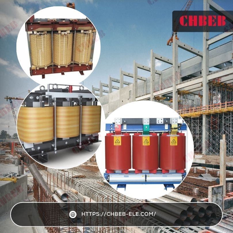
Conclusion
Dry-type transformers have evolved from simple oil-free devices into intelligent, eco-engineered power solutions. Using advanced insulation, smart air-cooling systems, and digital condition monitoring, they now deliver higher efficiency, safer operation, and sustainable performance across industries.
Every question engineers commonly ask — from how dry-type transformers dissipate heat to why solid insulation works without oil — finds its answer in real-world engineering and decades of testing. These technologies are not just theoretical concepts; they are field-proven solutions that power today’s smart grids, renewable projects, and industrial facilities with reliability and precision.
Backed by over 60 years of transformer manufacturing expertise, CHBEB continues to drive this evolution with IEC 60076-compliant dry-type designs, advanced VPI and Cast Resin technologies, and rigorous quality control from material selection to final testing. From smart cooling systems to precision core engineering, every CHBEB transformer represents the fusion of safety, efficiency, and innovation.
As global energy systems move toward sustainability and digital automation, CHBEB remains committed to delivering reliable power distribution solutions that set new standards for performance and trust — transforming engineering expertise into long-term value for clients worldwide.
