What is a Distribution Transformer?
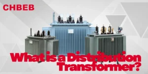
Introduction A distribution transformer is a static electrical device used in power distribution systems that transfers AC power by transforming voltage and current based on
Introduction A distribution transformer is a static electrical device used in power distribution systems that transfers AC power by transforming voltage and current based on
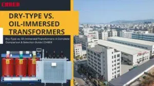
Choosing the wrong transformer causes project failures and high costs. Understanding their core differences is key to making the right choice for your power system’s

In-Depth Engineering: How Pad-Mounted Transformers Master the Heat Challenge Introduction In residential, business, and utility networks, pad-mounted transformers function quietly, but they are always combating

China Power Transformer Market Survey: Sourcing HV Capabilities and International OEM Solutions Introduction It can be hard to buy high-voltage transformers from China since there

Understanding IEEE Guide C57.91 for Loading Mineral-Oil-Immersed Transformers Introduction If you’ve ever been next to a buzzing transformer on a hot summer afternoon and thought,
From China to the World: A Complete Procurement and Logistics Guide for Substation-Grade Transformers Introduction Importing a substation transformer from China is no small task.
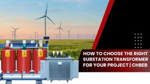
Substation Transformer Selection: The Ultimate Trade-Off Between Dry and Oil-Immersed Technologies | CHBEB Introduction Choosing the right transformer for a substation project is the most
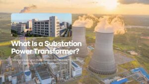
In-Depth Understanding: The Core Function and Grid Role of Substation Power Transformers Introduction A substation transformer is a silent workhorse that sits at the center
Introduction When a transformer enclosure fails, it’s never just a box issue — it’s a performance, safety, and certification problem. A trusted OEM/ODM partner ensures

Introduction The transformer substation1, a modest, silent green box that most people walk by every day, is important to every community. It could look normal,

Introduction The world’s energy infrastructure is getting smarter, greener, and safer. Dry-type systems that use modern materials, smart cooling, and safety that doesn’t leak are

Introduction When a transformer breaks down without warning, every hour of downtime costs money, puts strain on customers, and requires urgent calls to suppliers. In-stock