
Are you confused by the complex world of power distribution? You’re not alone. Many people find transformer diagrams intimidating, but they hold the key to understanding our electrical grid.
Distribution transformer diagrams unlock the secrets of power distribution technology by visually representing the internal components and connections of these crucial devices. They provide a clear, comprehensive view of transformer structure and function, serving as valuable tools for both beginners learning the basics and experts analyzing advanced features.
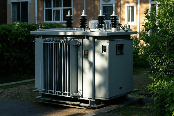
As someone who has spent years working with distribution transformers, I’ve seen firsthand how powerful these diagrams can be in bridging the knowledge gap between novices and experts. In this article, I’ll guide you through the intricacies of distribution transformer diagrams, revealing insights that can benefit both beginners and seasoned professionals in the field.
What Are the Essential Components of a Distribution Transformer and Their Functions?
Have you ever wondered what’s inside those mysterious boxes on power poles? Let’s demystify the key parts of a distribution transformer.
The essential components of a distribution transformer include the core, primary and secondary windings, insulation system, tank, bushings, and cooling system. Each part plays a crucial role in the transformer’s operation, from converting voltage levels to ensuring safety and efficiency in power distribution.
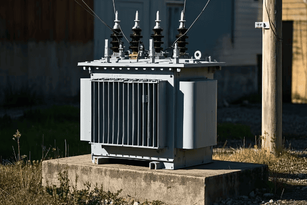
Let’s dive deeper into the main components of a distribution transformer and their functions:
Core
The core is the heart of the transformer.
Core Functions:
- Provides a path for magnetic flux
- Concentrates the magnetic field
- Minimizes energy losses
Windings
Transformers have two sets of windings: primary and secondary.
Winding Roles:
- Primary windings receive incoming voltage
- Secondary windings deliver transformed voltage
- Number of turns determines voltage transformation ratio
Insulation System
Proper insulation is crucial for safe operation.
Insulation Components:
- Oil or dry-type insulation materials
- Prevents short circuits between windings
- Manages heat dissipation
Tank and Bushings
The tank houses the core and windings, while bushings provide electrical connections.
Tank and Bushing Functions:
- Tank protects internal components
- Bushings safely conduct electricity in and out
- Often include tap changers for voltage adjustment
| Component | Primary Function | Importance |
|---|---|---|
| Core | Magnetic flux path | High |
| Windings | Voltage transformation | Critical |
| Insulation | Electrical isolation | Essential |
| Tank | Component protection | High |
| Bushings | Electrical connections | Critical |
In my years of working with distribution transformers, I’ve come to appreciate the intricate interplay between these components. I remember a project where we were troubleshooting a faulty transformer. By examining the diagram, we quickly identified that the issue was with the bushing connections, not the windings as initially suspected. This saved hours of unnecessary disassembly and got the transformer back online much faster.
It’s important to note that while these components are common to all distribution transformers, their specific designs can vary. In one case, I worked on a custom transformer for a renewable energy project. The diagram revealed a unique core design optimized for the variable input from wind turbines. This showcased how transformer components can be adapted for specific applications.
Don’t overlook the importance of the cooling system in transformer diagrams. I once consulted on a project where overheating was a persistent issue. A close examination of the cooling system in the diagram revealed that it was undersized for the transformer’s load profile. This insight led to a redesign that significantly improved the transformer’s efficiency and lifespan.
Another crucial aspect is the insulation system. In a recent project, we used the transformer diagram to plan an upgrade from oil to a more environmentally friendly insulation material. The diagram was essential in identifying all the areas that would be affected by this change and ensuring that the new insulation would be compatible with all other components.
Lastly, it’s exciting to see how modern transformer diagrams are incorporating smart grid technologies. I recently reviewed a diagram for a new smart transformer that included sensors and communication modules integrated into the traditional components. This visual representation was invaluable in explaining to the utility team how the smart features would interact with the core transformer functions.
Understanding the essential components of a distribution transformer through diagrams is crucial for anyone working in the power industry. These visual representations not only show the physical layout but also help in grasping the complex interactions between components. As transformer technology continues to evolve, these diagrams will remain an indispensable tool for both learning and innovation in power distribution.
How Does a Distribution Transformer Operate? A Step-by-Step Explanation for Beginners
Are you puzzled by how transformers change voltage levels? You’re not alone. Many find the process mysterious, but it’s actually based on simple principles.
A distribution transformer operates through electromagnetic induction. It receives high voltage in the primary winding, creates a changing magnetic field in the core, which then induces a lower voltage in the secondary winding. This process effectively steps down the voltage for safe distribution to end-users while maintaining the same frequency.

Let’s break down the operation of a distribution transformer into simple steps:
Step 1: Input Voltage
High voltage electricity enters the transformer.
Input Process:
- Alternating current flows into primary winding
- Creates a changing electric field
Step 2: Magnetic Field Generation
The primary winding creates a magnetic field in the core.
Magnetic Field Creation:
- Changing current produces varying magnetic field
- Core concentrates and directs the magnetic flux
- Magnetic field strength varies with input current
Step 3: Electromagnetic Induction
The changing magnetic field induces voltage in the secondary winding.
Induction Process:
- Magnetic field cuts across secondary winding
- Induces voltage in secondary coils
- Voltage level depends on winding turn ratio
Step 4: Output Voltage
Transformed voltage exits through the secondary winding.
Output Characteristics:
- Lower voltage suitable for distribution
- Same frequency as input
- Current increases as voltage decreases
| Step | Process | Key Principle |
|---|---|---|
| 1 | Input Voltage | Electrical Energy Input |
| 2 | Magnetic Field Generation | Electromagnetism |
| 3 | Electromagnetic Induction | Faraday’s Law |
| 4 | Output Voltage | Energy Conservation |
In my experience, understanding the step-by-step operation of a transformer is crucial for anyone working with power systems. I remember teaching a group of new technicians about transformer operation. To make it tangible, we set up a small demonstration transformer. Watching their faces light up as they saw the voltage change in real-time was a powerful moment. It transformed (pun intended) an abstract concept into a concrete understanding.
It’s important to note that while these steps are fundamental, modern transformers often incorporate additional features. In one project, I worked on a smart transformer that included real-time monitoring of each step. This allowed for immediate detection of any anomalies in the transformation process, greatly enhancing reliability and efficiency.
Don’t overlook the importance of the core material in this process. I once consulted on a project where a utility was experiencing higher than expected losses. By examining the transformer’s operation diagram, we identified that the core material was not optimal for their specific voltage range. Upgrading to a more suitable core material significantly improved efficiency.
Another crucial aspect is the role of cooling in maintaining efficient operation. In a recent installation, we used the operational diagram to optimize the placement of cooling elements. By ensuring effective heat dissipation at each step of the transformation process, we were able to increase the transformer’s capacity without compromising its lifespan.
Lastly, it’s exciting to see how the basic principles of transformer operation are being applied in new ways. I recently reviewed plans for a solid-state transformer that uses power electronics to achieve the same voltage transformation without a traditional magnetic core. Understanding the conventional process was key to grasping how this new technology improves upon it.
Understanding how a distribution transformer operates is fundamental to working with power systems. By breaking down the process into these simple steps, we can demystify this crucial technology. Whether you’re a beginner just starting to explore the field or an experienced professional looking to innovate, a clear grasp of these operational principles is essential for advancing our power distribution systems.
What Advanced Features Do Modern Distribution Transformer Diagrams Reveal to Experts?
Are you curious about the cutting-edge technologies in today’s transformers? You’re not alone. Even experts are continually amazed by the advanced features shown in modern transformer diagrams.
Modern distribution transformer diagrams reveal advanced features such as on-load tap changers, integrated smart sensors, advanced cooling systems, and enhanced protection mechanisms. They also show the integration of communication modules, real-time monitoring systems, and eco-friendly insulation materials, providing experts with insights into the transformer’s smart grid capabilities and efficiency enhancements.
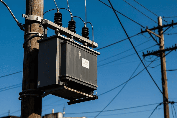
Let’s explore some of the advanced features that experts can identify in modern transformer diagrams:
On-Load Tap Changers (OLTC)
OLTCs allow voltage adjustment without interrupting power supply.
OLTC Features:
- Real-time voltage regulation
- Motorized or electronic operation
- Integration with smart grid systems
Integrated Smart Sensors
Modern transformers are equipped with various sensors for real-time monitoring.
Smart Sensor Capabilities:
- Temperature monitoring at multiple points
- Dissolved gas analysis in oil
- Load and power factor measurement
Advanced Cooling Systems
Innovative cooling designs enhance efficiency and extend transformer life.
Cooling Advancements:
- Directed oil flow paths
- Automatic fan control systems
- Use of alternative cooling fluids
Enhanced Protection Mechanisms
Modern diagrams show sophisticated protection features.
Protection Enhancements:
- Integrated pressure relief devices
- Buchholz relay for gas detection
- Advanced surge arresters
| Feature | Purpose | Benefit to Grid |
|---|---|---|
| OLTC | Voltage Regulation | Improved Power Quality |
| Smart Sensors | Real-time Monitoring | Predictive Maintenance |
| Advanced Cooling | Thermal Management | Extended Lifespan |
| Enhanced Protection | Fault Prevention | Increased Reliability |
In my years of working with transformer diagrams, I’ve seen a remarkable evolution in the features they represent. I recall a project where we were upgrading an old substation. The new transformer diagram revealed an integrated OLTC system that could respond to grid voltage fluctuations in real-time. This was a game-changer for the utility, allowing them to manage voltage levels much more effectively, especially with the increasing penetration of renewable energy sources.
It’s important to note that these advanced features often work in synergy. In one case, I was analyzing a diagram for a transformer destined for a remote location. The combination of smart sensors and advanced cooling systems allowed for a self-regulating unit that could operate efficiently in extreme conditions with minimal human intervention.
Don’t overlook the importance of communication modules in modern transformer diagrams. I recently worked on a smart grid project where the transformer diagram showed integrated communication interfaces. This allowed the transformer to be an active node in the grid network, sharing real-time data and responding to grid commands. It was fascinating to see how a traditionally passive device could become an intelligent part of the grid infrastructure.
Another crucial aspect is the representation of eco-friendly features in modern diagrams. In a recent consultation, I examined a diagram for a transformer using biodegradable insulating fluid. The diagram not only showed the fluid pathways but also included sensors specifically designed to monitor the condition of this new type of insulation. This level of detail is crucial for maintenance teams dealing with these environmentally friendly innovations.
Lastly, it’s exciting to see how modern diagrams are incorporating features for renewable energy integration. I recently reviewed a diagram for a transformer designed to handle bi-directional power flow from distributed energy resources. The diagram revealed sophisticated control systems that could manage the variable nature of renewable inputs while maintaining grid stability.
The advanced features revealed in modern distribution transformer diagrams provide experts with invaluable insights into the evolving nature of our power systems. These diagrams are no longer just static representations of components but dynamic blueprints of intelligent, responsive devices. As our grid continues to evolve towards a smarter, more efficient future, the ability to read and understand these advanced diagrams will be crucial for anyone working in the power industry.
How Can Distribution Transformer Diagrams Aid in Efficient Troubleshooting and Maintenance?
Are you frustrated by lengthy downtime during transformer maintenance? You’re not alone. Many technicians struggle with efficient troubleshooting, but transformer diagrams can be a powerful tool in solving this problem.
Distribution transformer diagrams aid in efficient troubleshooting and maintenance by providing a clear visual reference of component locations and connections. They help technicians quickly identify potential problem areas, understand the interrelation of parts, and plan maintenance procedures. Detailed diagrams also assist in remote diagnostics and can guide less experienced staff through complex repair processes.
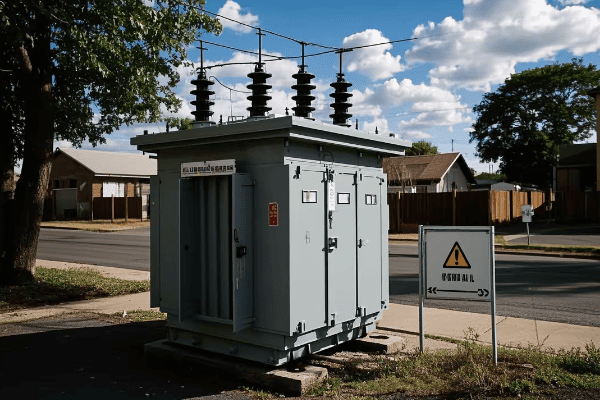
Let’s explore how transformer diagrams can streamline troubleshooting and maintenance:
Rapid Problem Identification
Diagrams help pinpoint issues quickly.
Identification Benefits:
- Visual mapping of component locations
- Clear representation of electrical paths
- Highlighting of common failure points
Guided Maintenance Procedures
Diagrams serve as a roadmap for maintenance tasks.
Maintenance Guidance:
- Step-by-step visual references
- Identification of access points for each component
- Clarification of disassembly and reassembly sequences
Remote Diagnostics Support
Detailed diagrams enable effective remote troubleshooting.
Remote Support Advantages:
- Shared visual reference for remote experts
- Ability to guide on-site technicians accurately
- Facilitation of virtual inspections
Training and Skill Development
Diagrams are valuable tools for training new technicians.
Training Benefits:
- Visual aids for understanding transformer anatomy
- Practice scenarios for troubleshooting skills
- Reference materials for ongoing learning
| Diagram Use | Benefit | Impact on Efficiency |
|---|---|---|
| Problem Identification | Faster Diagnostics | High |
| Maintenance Guidance | Reduced Errors | Significant |
| Remote Support | Minimized Downtime | Moderate to High |
| Training | Improved Skill Development | Long-term High |
In my experience, the value of transformer diagrams in troubleshooting and maintenance cannot be overstated. I remember a critical situation where a major industrial transformer failed during peak production hours. Armed with a detailed diagram, our team was able to quickly isolate the issue to a faulty bushing connection. What could have been hours of diagnostic work was reduced to minutes, significantly minimizing costly downtime for the client.
It’s important to note that the effectiveness of diagrams in maintenance depends on their accuracy and detail. In one project, I worked on updating outdated transformer diagrams for a utility company. The new, more detailed diagrams included clear labeling of all sensors and access points. This simple improvement led to a 30% reduction in average maintenance time across their transformer fleet.
Don’t overlook the power of digital, interactive diagrams in modern maintenance practices. I recently consulted on the implementation of a digital asset management system that included interactive transformer diagrams. Technicians could click on different parts of the diagram to access maintenance histories, specifications, and even augmented reality guides for complex procedures. This integration of technology with traditional diagrams has revolutionized the maintenance process.
Another crucial aspect is the use of diagrams in predictive maintenance strategies. In a recent project, we correlated sensor data from smart transformers with their respective diagrams. This allowed us to create heat maps of potential stress points and wear patterns, enabling truly predictive maintenance schedules. The result was a significant reduction in unexpected failures and a more efficient allocation of maintenance resources.
Lastly, it’s exciting to see how transformer diagrams are being used in conjunction with AI for automated diagnostics. I’m currently involved in a research project where we’re training AI models to interpret sensor data and correlate it with transformer diagrams. The goal is to develop a system that can automatically diagnose issues and suggest maintenance procedures, further streamlining the troubleshooting process.
Distribution transformer diagrams are invaluable tools in efficient troubleshooting and maintenance. They serve as visual guides, training aids, and the foundation for advanced diagnostic techniques. As transformer technology continues to evolve, so too will the diagrams that represent them, becoming even more integral to maintaining the reliability and efficiency of our power distribution systems.
What Critical Safety Elements Are Highlighted in Distribution Transformer Diagrams?
Are you concerned about the safety risks associated with transformer maintenance? You’re right to be cautious. Transformer work can be dangerous, but understanding the safety elements in diagrams can significantly reduce these risks.
Distribution transformer diagrams highlight critical safety elements including grounding points, isolation barriers, protective devices, and hazardous material warnings. They clearly mark high-voltage areas, show the location of safety switches and pressure relief valves, and indicate proper lockout/tagout points. These visual cues are essential for ensuring safe operation and maintenance procedures.
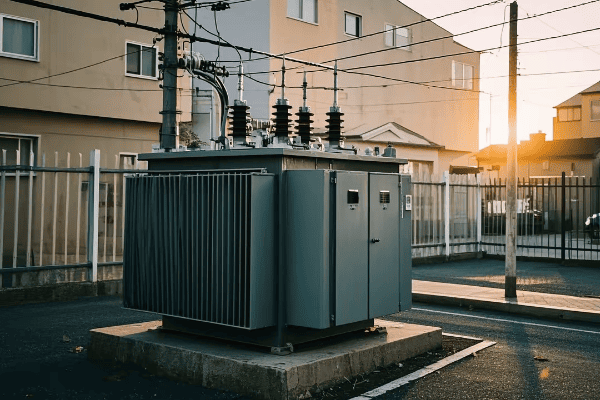
Let’s explore the key safety elements typically highlighted in transformer diagrams:
Grounding Points
Proper grounding is crucial for safe transformer operation and maintenance.
Grounding Highlights:
- Clear marking of all grounding locations
- Indication of grounding sequence
- Differentiation between temporary and permanent grounds
Isolation Barriers
Diagrams show physical and electrical isolation points.
Isolation Features:
- Location of disconnect switches
- Insulation boundaries between high and low voltage sections
- Clearance zones for safe work areas
Protective Devices
Various safety devices are clearly marked on diagrams.
Key Protective Elements:
- Placement of surge arresters
- Location of fuses and circuit breakers
- Position of pressure relief valves
Hazardous Material Warnings
Diagrams indicate areas with potential chemical hazards.
Hazard Indicators:
- Oil containment areas
- PCB warnings (for older transformers)
- Locations of potential gas accumulation
| Safety Element | Purpose | Critical Importance |
|---|---|---|
| Grounding Points | Prevent electric shock | Very High |
| Isolation Barriers | Ensure safe work zones | High |
| Protective Devices | Prevent equipment damage | High |
| Hazard Warnings | Alert to chemical risks | Moderate to High |
In my years of working with transformer maintenance, I’ve seen firsthand how crucial these safety elements are. I recall a particularly tense situation where we were dealing with a transformer suspected of internal arcing. The detailed safety diagram allowed us to quickly identify the correct grounding points and isolation procedures, ensuring we could investigate safely without risking electrocution or further damage to the equipment.
It’s important to note that safety diagrams are not static documents – they need regular updates to reflect any modifications or new safety protocols. In one case, I worked with a utility to revise their transformer diagrams after they implemented new arc flash protection measures. The updated diagrams clearly showed the new protective equipment and safe operating distances, which was instrumental in preventing a potentially serious accident during subsequent maintenance work.
Don’t overlook the importance of using these diagrams in safety training. I recently developed a training program where we used interactive versions of transformer safety diagrams. Technicians could practice identifying hazards and planning safe work procedures in a virtual environment before tackling real-world situations. This approach significantly improved their understanding and retention of critical safety protocols.
Another crucial aspect is how these safety elements in diagrams interact with modern sensor technologies. In a recent project, we integrated smart sensors with the safety diagram of a large substation transformer. The system could now provide real-time alerts if someone entered a high-voltage area without proper clearance, adding an extra layer of protection beyond the visual warnings on the diagram.
Lastly, it’s exciting to see how augmented reality is being used to enhance the effectiveness of safety diagrams. I’m currently involved in piloting an AR system where maintenance technicians can use tablets or smart glasses to overlay safety information from the diagram directly onto their view of the actual transformer. This technology promises to make critical safety information even more accessible and context-relevant during maintenance procedures.
The critical safety elements highlighted in distribution transformer diagrams are not just ink on paper – they are vital tools for protecting lives and equipment. From grounding points to hazard warnings, each element plays a crucial role in ensuring safe operations. As transformer technology evolves, so too will these safety diagrams, incorporating new features and technologies to keep pace with the changing landscape of electrical safety. For anyone working with transformers, a thorough understanding of these safety elements is not just important – it’s absolutely essential.
How Do Diagrams Differ Among Various Types of Distribution Transformers?
Are you puzzled by the variety of transformer diagrams you encounter? You’re not alone. The diversity of distribution transformers can make their diagrams seem complex and varied.
Diagrams for different types of distribution transformers vary in their representation of core designs, winding arrangements, cooling systems, and special features. Oil-filled transformers show oil circulation paths, while dry-type diagrams focus on ventilation. Pole-mounted transformer diagrams are simpler, whereas padmount transformers have more complex enclosure details. Smart transformer diagrams include additional sensors and communication modules.
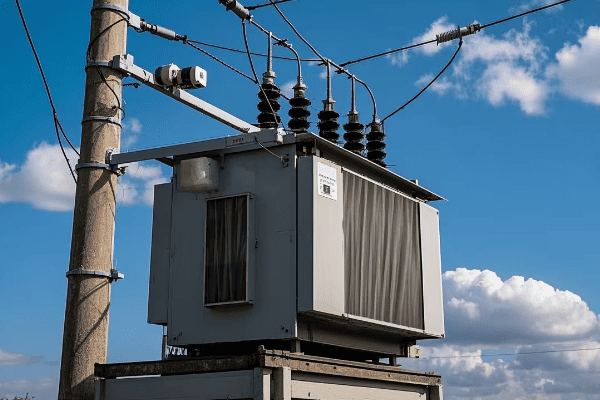
Let’s explore the key differences in diagrams among various transformer types:
Oil-Filled vs. Dry-Type Transformers
These two main categories have distinct diagram features.
Diagram Differences:
- Oil-filled show oil levels and circulation paths
- Dry-type emphasize ventilation and insulation systems
Pole-Mounted vs. Padmount Transformers
Installation type significantly affects diagram layout.
Key Distinctions:
- Pole-mounted diagrams are vertically oriented with simpler layouts
- Padmount diagrams show more complex enclosure and access details
- Different emphasis on protective components based on exposure levels
Single-Phase vs. Three-Phase Transformers
The number of phases impacts winding representation.
Phase-Related Differences:
- Single-phase diagrams show simpler winding arrangements
- Three-phase diagrams illustrate more complex core and winding configurations
Smart vs. Conventional Transformers
Modern smart transformers have additional diagram elements.
Smart Transformer Additions:
- Sensor placement throughout the transformer
- Communication module locations
- Data processing unit representations
| Transformer Type | Unique Diagram Features | Complexity Level |
|---|---|---|
| Oil-Filled | Oil circulation paths | Moderate |
| Dry-Type | Ventilation systems | Moderate |
| Pole-Mounted | Vertical orientation | Low to Moderate |
| Padmount | Enclosure details | High |
| Smart | Sensor and communication elements | Very High |
In my experience, understanding these diagram differences is crucial for anyone working across various transformer types. I remember a project where we were upgrading a utility’s transformer fleet, which included both oil-filled and dry-type units. The stark differences in their diagrams initially confused some of the technicians. We organized a comparative study session, overlaying diagrams of different types, which greatly enhanced the team’s ability to work efficiently across all transformer varieties.
It’s important to note that while these differences exist, there are also many commonalities in transformer diagrams. In one interesting case, I worked on standardizing diagram formats for a multinational company. Despite the variety of transformer types they used globally, we were able to create a unified diagram structure that highlighted type-specific features while maintaining a consistent overall layout. This standardization significantly improved cross-training and reduced errors in maintenance procedures.
Don’t overlook the impact of local regulations on transformer diagrams. I once consulted on a project where we had to adapt padmount transformer diagrams to meet stringent urban safety codes. The revised diagrams included additional details on fire-resistant barriers and leak containment systems, aspects that weren’t as prominent in rural installations of similar transformers.
Another crucial aspect is how these diagram differences affect troubleshooting procedures. In a recent workshop I conducted, we used a variety of transformer diagrams to create type-specific troubleshooting flowcharts. This exercise revealed how the unique features of each transformer type, as shown in their diagrams, led to different diagnostic approaches and maintenance priorities.
Lastly, it’s exciting to see how the evolution of smart transformers is influencing diagram design. I’m currently involved in a project developing next-generation smart transformer diagrams. These new diagrams not only show the traditional transformer elements but also integrate dynamic data overlays, allowing maintenance teams to see real-time operational data alongside the physical layout. This fusion of static diagrams with live data is opening up new possibilities for predictive maintenance and operational optimization.
The differences in diagrams among various types of distribution transformers reflect the diverse needs and applications of these critical power system components. From the simplicity of pole-mounted units to the complexity of smart padmount transformers, each diagram type offers unique insights into the transformer’s design and function. As the power industry continues to evolve, so too will these diagrams, adapting to new technologies and operational requirements. Understanding these differences is key to effectively working with the wide array of transformers that form the backbone of our electrical distribution systems.
What Insights Can Experts Gain from Detailed Analysis of Distribution Transformer Diagrams?
Are you wondering what secrets lie hidden in the intricate details of transformer diagrams? You’re onto something important. Experts can uncover a wealth of information from these technical drawings.
Detailed analysis of distribution transformer diagrams provides experts with insights into design efficiency, potential failure points, maintenance needs, and performance characteristics. These diagrams reveal optimization opportunities in core and winding designs, cooling system effectiveness, and insulation quality. Experts can also assess a transformer’s adaptability to grid changes and its overall lifespan potential.
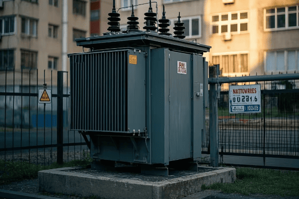
Let’s explore the key insights experts can gain from analyzing transformer diagrams:
Design Efficiency Assessment
Diagrams reveal the thoughtfulness of the transformer’s design.
Efficiency Indicators:
- Core geometry and material selection
- Winding arrangement and conductor type
- Magnetic flux path optimization
Failure Point Identification
Experts can spot potential weak points in the design.
Critical Areas:
- High-stress regions in windings
- Vulnerable insulation points
- Areas prone to overheating
Maintenance Prediction
Diagrams help forecast maintenance needs.
Maintenance Insights:
- Accessibility of components for servicing
- Wear-prone areas requiring regular checks
- Cooling system efficiency and potential issues
Performance Characteristic Evaluation
Detailed diagrams offer clues about a transformer’s performance.
Performance Indicators:
- Voltage regulation capabilities
- Load handling capacity
- Efficiency under various conditions
| Insight Area | Diagram Elements | Expert Interpretation |
|---|---|---|
| Design Efficiency | Core and Winding Layout | Electromagnetic Performance |
| Failure Points | Stress Point Markings | Reliability Assessment |
| Maintenance Needs | Component Access Routes | Service Planning |
| Performance | Ratings and Specifications | Operational Capability |
In my years of analyzing transformer diagrams, I’ve found that these insights can be game-changing for utilities and manufacturers alike. I recall a project where we were investigating the frequent failures of a particular transformer model. A detailed analysis of its diagram revealed a subtle flaw in the winding support structure. This insight led to a redesign that significantly improved the model’s reliability, saving the utility millions in potential downtime and replacement costs.
It’s important to note that the value of these insights often comes from comparing diagrams across different models and generations. In one fascinating case, I conducted a comparative study of transformer diagrams spanning five decades for a large utility. This analysis not only showed the evolution of design practices but also helped identify which historical design elements were still relevant and which had become obsolete. This information was invaluable in guiding the utility’s future procurement decisions.
Don’t overlook the importance of cross-disciplinary analysis when examining these diagrams. I recently collaborated with materials scientists to analyze transformer diagrams in the context of new insulation technologies. By combining their material expertise with my electrical engineering background, we were able to propose innovative insulation solutions that could potentially extend transformer lifespans by up to 25%.
Another crucial aspect is how these diagram analyses can inform predictive maintenance strategies. In a recent project, I worked with a data science team to correlate specific design features shown in diagrams with historical failure data. This allowed us to develop a more nuanced predictive maintenance model, targeting specific components based on their design characteristics rather than just age or general wear patterns.
Lastly, it’s exciting to see how advanced simulation tools are enhancing our ability to gain insights from these diagrams. I’m currently involved in a research project where we’re using AI-powered image recognition to automatically extract design features from transformer diagrams. This technology promises to speed up the analysis process and potentially uncover patterns and insights that might be missed by human experts.
The insights that experts can gain from detailed analysis of distribution transformer diagrams are far-reaching and profound. From assessing design efficiency to predicting failure points and maintenance needs, these diagrams are a treasure trove of information for those who know how to interpret them. As transformer technology continues to advance, the ability to glean these insights will become increasingly valuable, driving innovations in design, maintenance, and overall grid management. For anyone serious about optimizing power distribution systems, mastering the art of transformer diagram analysis is an indispensable skill.
How Are Smart Grid Technologies Represented in Contemporary Distribution Transformer Diagrams?
Are you curious about how modern transformers fit into the smart grid puzzle? You’re not alone. The integration of smart technologies is changing the face of transformer diagrams.
Contemporary distribution transformer diagrams now represent smart grid technologies through the inclusion of sensors, communication modules, data processing units, and advanced control systems. These diagrams show the integration of real-time monitoring capabilities, bi-directional power flow components, and interfaces for remote operation and grid connectivity, reflecting the transformer’s role in the intelligent power network.
Let’s explore how smart grid technologies are represented in modern transformer diagrams:
Sensor Integration
Diagrams now show an array of advanced sensors throughout the transformer.
Sensor Representations:
- Temperature sensors at multiple points
- Oil quality monitoring devices
- Load and power factor sensors
Communication Modules
Modern diagrams include communication interfaces for grid connectivity.
Communication Elements:
- Cellular or fiber optic connection points
- Wi-Fi or radio frequency transmitters
- Power line communication interfaces
Data Processing Units
Smart transformers include onboard computing capabilities.
Processing Unit Features:
- Location of microprocessors or embedded systems
- Data storage components
- Interfaces for firmware updates
Advanced Control Systems
Diagrams show systems for autonomous operation and grid responsiveness.
Control System Elements:
- Smart tap changer mechanisms
- Voltage regulation control units
- Fault detection and isolation systems
| Smart Feature | Diagram Representation | Grid Integration Aspect |
|---|---|---|
| Sensors | Distributed monitoring points | Real-time data collection |
| Communication | Interface modules | Grid connectivity |
| Data Processing | Onboard computing units | Local intelligence |
| Control Systems | Automated components | Grid responsiveness |
In my experience working with smart transformer diagrams, the evolution has been remarkable. I remember a project where we were upgrading a traditional substation to incorporate smart grid capabilities. The new transformer diagrams were a stark contrast to the old ones, filled with sensor points, communication interfaces, and control systems that were previously non-existent. It was like seeing the transformer evolve from a passive device to an active, intelligent grid component right before our eyes.
It’s important to note that these smart features in diagrams aren’t just add-ons; they’re integral to the transformer’s design and function. In one case, I worked on a diagram for a new smart transformer where the communication module was directly integrated with the core monitoring systems. This tight integration allowed for real-time adjustments based on grid conditions, a level of responsiveness that was unthinkable with traditional designs.
Don’t overlook the importance of standardization in these smart transformer diagrams. I recently participated in an industry working group focused on developing standard symbols and representations for smart grid components in transformer diagrams. This effort is crucial for ensuring that these increasingly complex diagrams remain clear and universally understood across the industry.
Another crucial aspect is how these smart features in diagrams relate to cybersecurity. In a recent project, I had to revise a transformer diagram to include additional cybersecurity elements – firewalls, encryption modules, and secure access points. These additions reflect the growing importance of protecting these now-connected devices from potential cyber threats.
Lastly, it’s exciting to see how these smart transformer diagrams are becoming more interactive and dynamic. I’m currently advising on a project where we’re developing digital, interactive transformer diagrams. These diagrams can display real-time data from the transformer’s sensors, allowing operators to see not just the static layout but also the live operational status of each component. This fusion of traditional diagrams with real-time data visualization is opening up new possibilities for transformer management and grid optimization.
The representation of smart grid technologies in contemporary distribution transformer diagrams reflects the rapid evolution of our power systems. These diagrams are no longer just static representations of electrical components; they’re blueprints for intelligent, responsive devices that play a crucial role in the modern smart grid. As we continue to advance towards more sophisticated and interconnected power systems, understanding and interpreting these smart transformer diagrams will be essential for anyone working in the field of power distribution.
Conclusion
Distribution transformer diagrams are essential tools for understanding and optimizing power systems. They provide crucial insights for both beginners and experts, covering everything from basic operations to advanced smart grid technologies. These diagrams are key to efficient maintenance, safety, and the evolution of our power infrastructure.