Introduction
It’s not easy to pick a brand of transformer. There are too many names and too much language, and making the wrong pick might cost you more and put your safety at danger. This guide tells you about the trends, top brands, and easy shopping tips for 2025 so you can make a smart choice.
The 2025 Market Landscape: Key Drivers and Trends
A lot of initiatives fail when customers don’t notice changes in the market. Demand for dry-type goods is rising for safety, environmental aims, and digital monitoring. This is what is causing growth and how it will effect your project.
From renewable energy to smart cities, growth drivers
- Wind and solar power work best with dry-type devices that are safe from fire and oil.
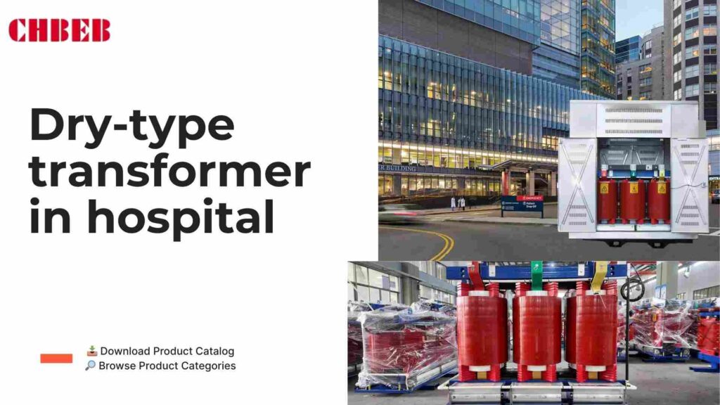
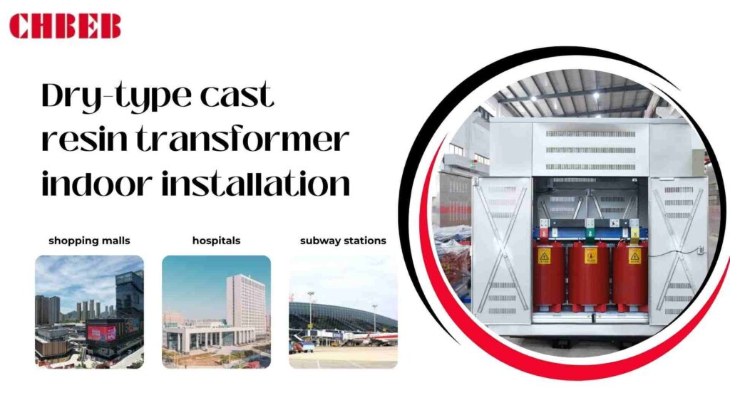
- Smart cities: malls, hospitals, and subways need safer indoor transformers.
- More EV1 charging stations need reliable MV dry-type solutions.
- Regulation: Stricter restrictions about fires and the environment are making dry-type more popular.
For example, industry forecasts say that demand for dry-type goods could expand by about 6% each year until 2030.
Trends in technology: More and more digital and eco-friendly transformers
- Digital monitoring: Sensors keep an eye on health and temperature in real time.
- Eco-friendly materials: Resin systems and parts that can be recycled help the environment.
- Compact designs: Smaller, modular devices take up less area and are cheaper to install.
- Ready for renewable energy: Custom choices work nicely with inverters and storage.
Profiles of the best dry-type transformer brands in the world
Different brands have different strengths. A bad match can cause delays or problems with compliance. Use this quick look at the leaders of 2025 to help you narrow down your list.
Hitachi Energy2 (ABB): The World Leader in Digital and Eco-Friendly Solutions
- Key strength: designs that focus on the environment and digital monitoring that is the best in its class.
- Why it matters: It’s a safe and reliable alternative for projects with a lot of demand.
- Where it is used: data centers, utility grids, and wind farms.
- Tip: Strong analytics make it a good choice for offshore wind.
Siemens Energy: The Powerhouse of the Industry and Infrastructure
- Key strength: High efficiency and little loss.
- Why it matters: It saves energy and is stable for lengthy duty cycles.
- Where it is used: hospitals, rail lines, and industrial complexes.
- Tip: This is very common in metro systems where uptime is very important.
The Digital and Energy Management Expert at Schneider Electric
- One of its best features is that it works well with EcoStruxure™ for predictive maintenance.
- Why it matters: It’s straightforward to use and keeps people safe inside.
- Smart buildings, colleges, and businesses all use it.
- Tip: This is common in hospitals and malls to follow fire codes.
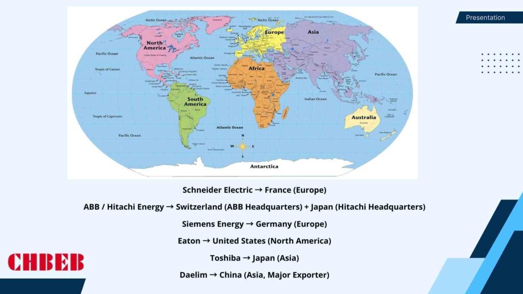
Eaton and Other Important Players
- Eaton: VPI designs that are easy on the wallet and good service in North America.
- Toshiba: Works well in APAC and is suitable for projects with a lot of infrastructure.
- Daelim and TBEA are new competitors with low prices and a lot of exports.
- Local suppliers: They can supply faster and know a lot about local codes.
Strategic Analysis: A Buyer’s Guide for 2025
Just looking at brand names can be misleading. Look at the strengths and see how they fit your needs. The view below, which shows things side by side, makes judgments easy and useful.
Key Differentiators: A Side-by-Side Comparison
| Brand | What They’re Best At | Best Applications | Global Reach | Buyer Concern Solved |
|---|---|---|---|---|
| Hitachi Energy | Digital monitoring, eco solutions | Utilities, renewables, data hubs | Global | Compliance, real-time visibility |
| Siemens Energy | Efficiency, infrastructure expertise | Transport, hospitals, industry | Global | Low losses, high uptime |
| Schneider Electric | Digital platform, fire safety | Buildings, campuses, malls | Global | Indoor safety, easy O&M |
| Eaton | Cost-effective VPI | Mid-size industry, NA market | North America | Budget control, quick service |
| Toshiba | APAC reliability | Infrastructure projects | Asia-Pacific | Long-term durability |
Choosing: How to Match Brands to Applications
- Utilities or renewables? Pick either Siemens or Hitachi Energy.
- Projects inside? Schneider is a better and safer alternative.
- Short on cash? Think about Eaton or strong local suppliers.
- Important places? For hospitals and metros, use cast resin from big brands.
A Look Ahead at the Market’s Future
- AI monitoring: Transformers that can find faults on their own.
- Greener buildings: using materials that can be recycled becomes normal.
- Local sourcing: Work with regional partners and global brands.
- Customization: More unique designs for storage and renewables.
Conclusion
In 2025, dry-type transformers will continue to evolve around safety, sustainability, and digital intelligence. Global leaders like Hitachi Energy, Siemens, and Schneider offer strong brand value, while cost-effective players such as Eaton, Toshiba, and Daelim meet regional demands.
However, beyond these names, source manufacturers like CHBEB Power provide unique advantages: faster delivery (7–15 days for standard units), flexible OEM/ODM customization, and proven compliance with IEC/ANSI standards. For many EPCs, utilities, and industrial clients, this balance of quality and agility delivers the best long-term value.
“The value of an idea lies in the using of it.” — Thomas Edison
Bottom line: Choosing the right transformer is not just about a name—it’s about matching real project needs with reliable technology, service, and cost control.
Learn More
Want to explore more transformer solutions? Download our latest product catalog or browse our product categories to find the right transformer for your project.
Introduction
Power transformers are very important for sending and receiving power, but how they are built on the inside is still a mystery. Not knowing parts can lead to bad design, slow performance, and problems with maintenance. This book goes into great detail about how transformers are built, focusing on how each item affects safety, dependability, and long-term performance.
Part 1: The Main Part of How the Transformer Works
The active parts of a transformer are what make it work. The transformer can’t safely operate or convert voltage stably if the core, windings, or insulation are badly built. Both purchasers and engineers need to know about these interior parts.
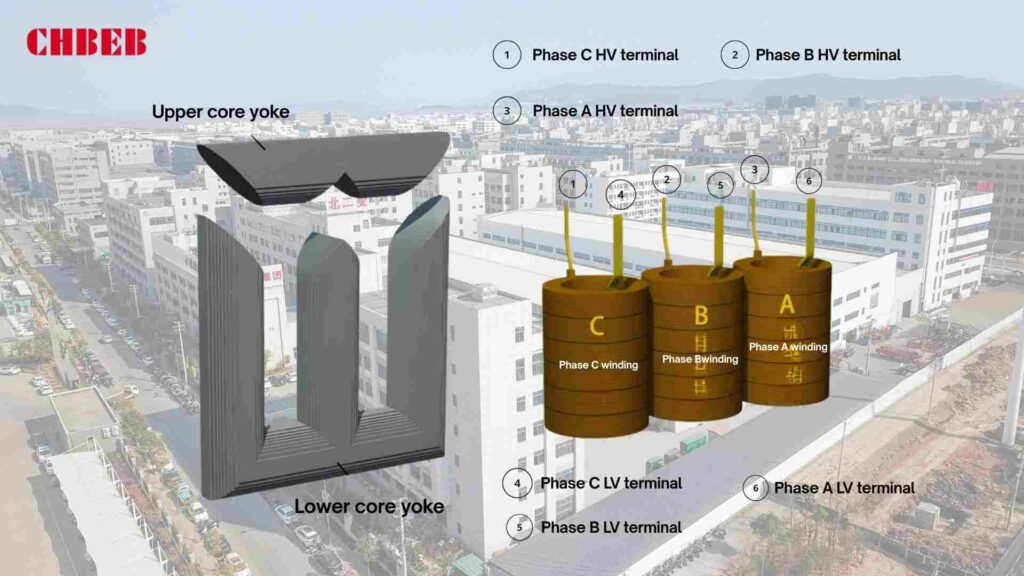
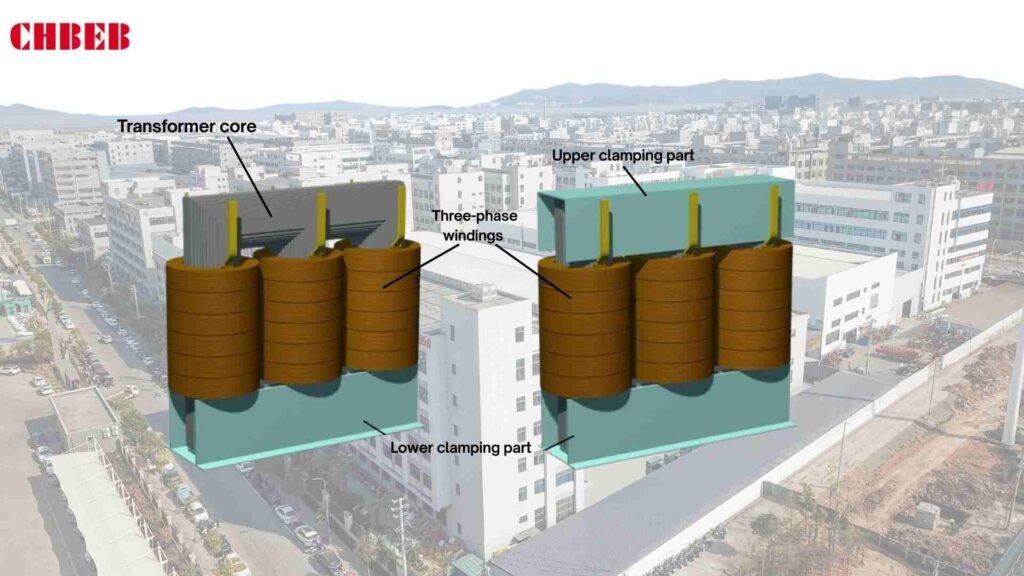
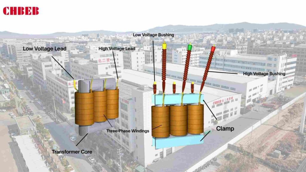
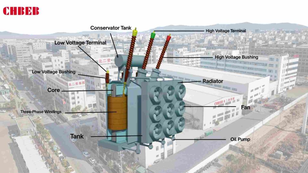
The Magnetic Core1: The Transformer’s Frame
The magnetic core makes the skeleton of the transformer and gives the flux a path. It is usually built of laminated silicon steel sheets to cut down on losses from eddy currents. Amorphous alloy cores can be employed in designs that need to be very efficient. The shape of the core (core-type or shell-type) has a direct effect on the amount of loss, the strength of the structure, and the noise.
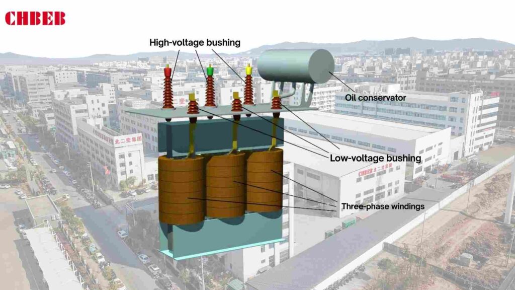
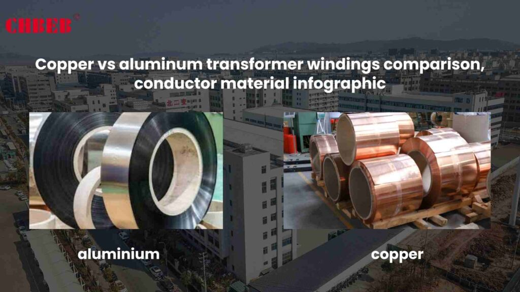
The Windings: The Transformer Core
Windings change the voltage of electrical energy. They are made of copper2 or aluminum conductors and are stacked in layers of high and low voltage. The low-voltage winding is usually closer to the core, and the high-voltage winding surrounds it. Buyers have to make a big choice between copper and aluminum since it impacts efficiency, short-circuit strength, and cost.
Insulation and cooling are the system’s lifeblood.
Insulation stops electrical problems from happening between the core and the windings. Pressboard, resin, and oil for liquid-filled transformers, or epoxy resin for dry-type designs are some of the materials used. Cooling systems get rid of the heat that builds up during use:
- Oil-immersed transformers: Mineral or ester oil provides both insulation and cooling. Heat dissipates through radiators or oil pumps with fans.
- Dry-type transformers3: Windings are encapsulated in epoxy resin, with natural or forced air cooling.
Both insulation and cooling affect how long something will last, how safe it is to use, and how well it can handle a load.
Part 2: The Transformer’s Systems for Support and Protection
Transformers need more than simply active parts to work. They also need external mechanisms to keep them secure and safeguard them. These parts protect against stress from the environment, electrical problems, and changes in voltage.
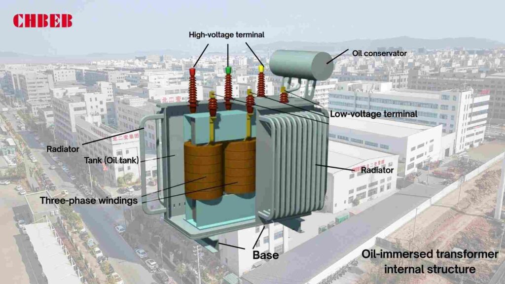
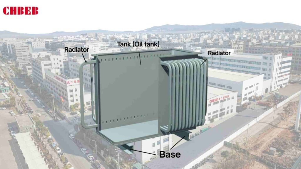
The Tank and Conservator: The Housing That Protects
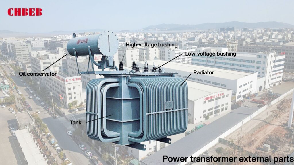
The oil tank, which is sometimes called the transformer tank, holds the active parts and is filled with insulating oil. There are radiator fins or cooling pipes around the tank that let heat escape. Forced circulation is done via external oil coolers and fans on bigger units.
The conservator, or oil reservoir, makes up for the oil expanding when the temperature changes. Sealed metal bellows or bladder-type conservators are typically used in modern designs to keep oil separate from air. This keeps moisture from getting into the oil and keeps it from oxidizing. For smaller facilities, sealed tanks with corrugated fins can be utilized instead of a conservator.
The Guardian Devices: The Buchholz Relay and Breather
For transformers that are filled with oil, protection is very important:
- Buchholz relay: This device is put between the main tank and the conservator. It detects gas buildup or abrupt oil movement and sends out early fault alerts and trip signals.
- Breather: Usually filled with silica gel, it filters and dries the air that comes into the conservator. This keeps the insulation oil from being too wet.
These devices work together to protect transformers, making them last longer and keeping them safe.
The Tap Changer is the voltage regulator.
Transformers need to change the output voltage because demand and the grid change. Tap changers vary the turns ratios in the winding to control voltage::
- Off-load tap changers: You have to replace them by hand when the transformer is not working.
- On-load tap changers (OLTC) automatically alter the voltage while the system is powered on, making sure that the supply never stops.
Tap changers are very important for keeping the grid stable and safe for sensitive equipment.
Part 3: Putting It All Together: Types of Construction and Common Problems
Even with good parts, a bad overall design might cause problems. Buyers may make smart choices about how to maintain and buy transformers by learning about the many types of transformers and the problems they often have.
A Look at Structural Design: Core-Type vs. Shell-Type
- Core-Type Transformers: The windings go around the core’s limbs. This design is common for high-voltage uses and makes it easier to cool down.
- Shell-Type Transformers: The core surrounds the windings, which makes them stronger and better able to handle faults. This kind is widely utilized in power plants and other big industrial settings.
The size of the application, the voltage level, and the cost are all factors that affect the choice between core and shell kinds.
Linking Parts to Common Issues and Answers
- Core: Bad lamination can lead to a lot of noise and losses. Solution: Use tight clamping and high-quality silicon steel.
- Windings: When they get too hot, the insulation breaks down. The answer is to use the right size conductor and good insulation.
- Insulation and cooling: Hot spots happen when oil spills or air passages get blocked. The answer is to check the oil and the ventilation on a regular basis.
- Tank and conservator: Leaks happen when gaskets wear out or corrode. Routine checks and maintenance are the answer.
- Buchholz relay and breather: A broken relay or too much silica gel can make protection less effective. Solution: Testing the relay and changing the gel on a regular basis.
- Tap changer: Failures happen when contacts wear out or arc. Scheduled maintenance and oil filtering are the answers.
Maintenance staff may take action before problems happen by tying them to parts. This cuts down on downtime and extends the life of assets.
Conclusion
A power transformer is more than just copper windings inside a steel tank. Its performance depends on a careful balance of the magnetic core, windings, insulation, cooling, protective devices, and housing.
For engineers, understanding these parts means better specifications, fewer failures, and longer service life. For beginners, it’s enough to remember that every component has a role: the core carries the magnetic flow, the windings carry electricity, the insulation keeps it safe, the oil or air keeps it cool, and devices like the Buchholz relay or tap changer keep it stable and protected.
When these pieces come together with good design and proper maintenance, the result is a transformer that runs safely, efficiently, and reliably for decades—powering everything from homes and hospitals to factories and renewable plants.
- Transformer Construction — Wikipedia ↩︎
- Copper and Aluminium Windings in Transformers — ScienceDirect ↩︎
- Transformer Cooling Methods — All About Circuits ↩︎
Learn More
Want to explore more transformer solutions? Download our latest product catalog or browse our product categories to find the right transformer for your project.
Introduction
It can be hard to choose the correct dry-type transformer1 maker. Safety, technical gaps, and cost trade-offs are things that buyers often have trouble understanding. This book looks at industry trends, the best worldwide suppliers, and the most important factors to consider when choosing a partner for your project.
Part 1: An Overview of the Market and Its Main Technologies
When you don’t have any context, you have to guess when you make a purchase. A lot of people don’t know why dry-type transformers are becoming more popular. By looking at the factors that drive the market and the differences in technology, you can be sure that your selections are in line with the needs of your project and that your investment will last.
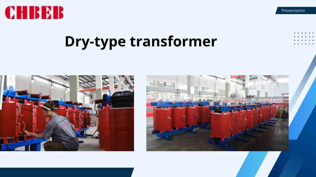
Why Dry-Type Transformers Are Becoming More Popular: Safety, the Environment, and Key Drivers
People are choosing dry-type transformers more and more because they are naturally safe from fire, good for the environment, and work well indoors. Key factors are:
- Safety: No flammable liquid, lower fire danger, great for places with a lot of people.
- No oil leaks, less maintenance, and recyclable materials are good for the environment.
- Urbanization: More and more hospitals, schools, malls, data centers, and underground substations are using them.
- Regulation: Stricter fire and environmental rules make it more likely that dry-type will be used.
Cast Resin vs. Vacuum Pressure Impregnated (VPI)2: A Technology Showdown
There are two main technologies that rule the dry-type market:
- Cast Resin: Windings are wrapped in epoxy resin, which makes them very strong and resistant to moisture. This type of resin is good for humid or coastal areas.
- VPI (Vacuum Pressure Impregnated): Windings that have been soaked in varnish under vacuum and pressure. They are flexible, cost-effective, and can handle more thermal cycling.
It depends on the environment, the load profile, and the project’s priorities which one to use.
Part 2: Profiles of the World’s Best Manufacturers
Buyers risk making bad partnerships if they don’t know what each provider is good at. By looking at the best players, you’ll have a better idea of who is best at digitalization, heavy industry, or infrastructure. This will make sure that your project gets the proper competence.
Schneider Electric: The First Company to Use Digital Technology and Smart Grids
Schneider Electric is the best at putting dry-type transformers into digital systems. Their EcoStruxure™ technology lets you keep an eye on things in real time, plan maintenance ahead of time, and save energy. They are a great alternative for digital-ready projects because they are well-known in data centers, commercial buildings, and smart buildings.
ABB (Hitachi Energy): The World’s Biggest Utility and Heavy Industry Company
ABB, which is now part of Hitachi Energy, is the best at doing large industry and utility-scale work. Their cast-resin and VPI designs are very sturdy and work well in difficult industrial environments, high power settings, and situations where renewable energy is used. Global service networks make sure that help is available in practically every corner of the world.
Siemens Energy: The Industry & Infrastructure Expert
Siemens Energy works on infrastructure, industrial automation, and making sure that energy is always available. Their dry-type transformers have superior insulation, minimal losses, and small footprints. They are good for infrastructure and transportation projects since they can be customized and have engineering support.
Other Important Global Suppliers
- Eaton: Makes adaptable VPI designs for businesses and factories.
- Toshiba: Known for being reliable throughout Asia-Pacific and in projects with a lot of infrastructure.
- Daelim is a developing player that focuses on exports and offers reasonable prices.
- Local champions: Suppliers in the area often offer affordable solutions that meet local codes.
Part 3: Comparative Analysis & Purchasing Strategy
Just looking at the price doesn’t tell you how much anything is worth. A lot of purchasers don’t think about service, lifecycle expenses, or vendor stability. A organized comparison makes sure you get not just the equipment you need, but also dependable help and savings over time.
Multi-Dimensional Comparison: Product, Service, and Market Position
| Manufacturer | Technology Focus | Market Strength | Best Fit |
|---|---|---|---|
| Schneider Electric | Cast Resin, Digital Integration | Strong in smart buildings & data centers | Digital-ready, efficiency-focused projects |
| ABB / Hitachi Energy | Cast Resin & VPI | Utility & heavy industry | Large-scale renewables, utility grids |
| Siemens Energy | Cast Resin | Infrastructure & transport | Industrial, transport, infrastructure |
| Others (Eaton, Toshiba, Daelim) | VPI & Cast Resin | Regional strength, competitive pricing | Cost-sensitive or localized projects |
How to Choose the Best Option for Your Project
- Set the kVA, voltage, environment, and fire/safety codes as required.
- Check out the technology: Cast Resin vs. VPI for load and climate.
- Look at the costs over the life of the product, including losses, maintenance, and downtime concerns.
- Check the vendor’s support: is it available globally or only in certain areas?
- Make sure that the certifications IEC, IEEE/ANSI, CE, and UL are all up to date.
- Think about customization: special enclosures, noise, and monitoring.
To get the most out of your dry-type transformer investment, you need to be sure that it fits technically, is compliant, and is from a reliable source.
Conclusion
Safety, sustainability, and digital integration are shaping the global market for dry-type transformers. Well-known manufacturers like Schneider Electric, ABB/Hitachi Energy, and Siemens Energy set high benchmarks in technology, certification, and worldwide service networks, making them the preferred choice for utility-scale, industrial, and infrastructure projects.
At the same time, regional and local manufacturers also play a vital role. They often provide faster delivery, competitive pricing, and flexible customization that global giants may not always offer. For projects in emerging markets or with unique requirements, these manufacturers can deliver reliable, efficient, and standards-compliant solutions tailored to local conditions.
As Nikola Tesla once said, The spread of electricity will do more to improve life on earth than any other single advance.
In the same spirit, whether from a global leader or a trusted regional supplier, dry-type transformers remain essential to powering communities safely, sustainably, and reliably for decades.
Learn More
Looking for the right dry-type transformer for your project? Download our latest product catalog or browse our product categories to find reliable solutions tailored to your needs.
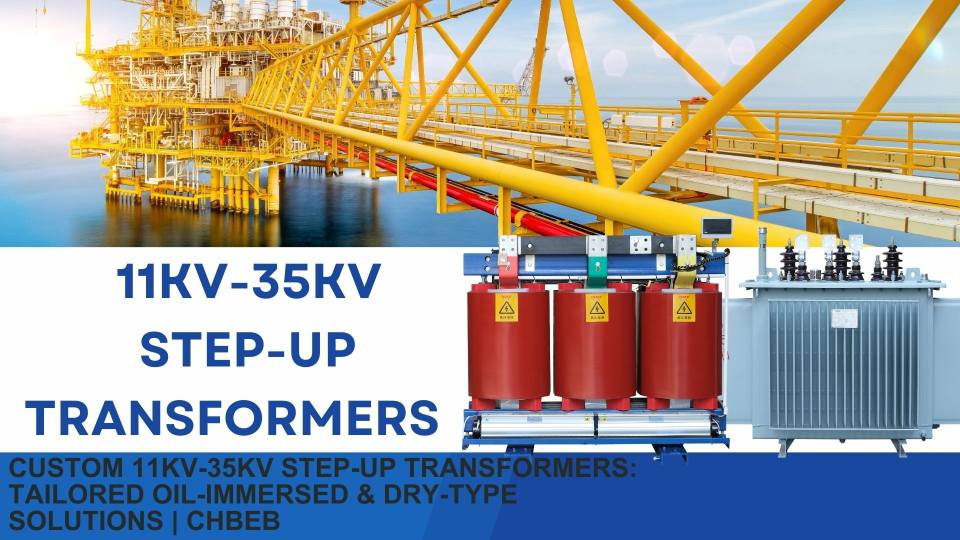
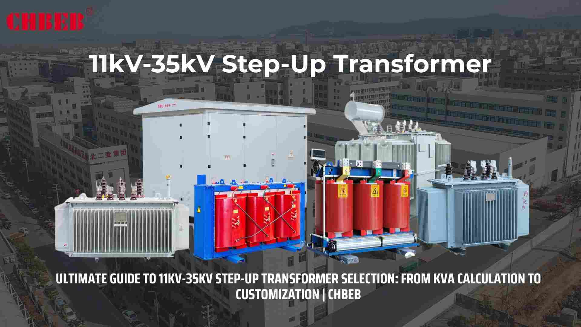
Introduction
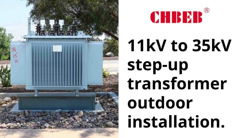
Standard transformers often don’t meet important needs. The outcome is extra effort, lost time, and money. Custom 11–35 kV step-up transformers fix voltages, footprints, and duties that aren’t conventional. They make connections safer, work more efficiently, and cost the least over the life of the project.
Why Get a Custom Transformer? The Value Proposition
Off-the-shelf systems have trouble with strange voltages, limited space, and environmental dangers. These gaps lead to change orders and time off work. Custom engineering makes sure that electrical, mechanical, and compliance demands are all met from the start. This lowers risk, boosts performance, and protects budgets for decades.
Finding solutions to power and space problems that aren’t standard
Instead of making the site fit the transformer, custom designs take into account real-world limitations. Some of the problems we solve are:
- Hybrid systems, specialized phase shifts, neutral availability, and grounding techniques are all examples of non-standard voltages and vector groups
- Tight footprints and weight limits: small tanks, low-profile radiators, or split modules for pads and rooftops that don’t have a lot of space.
- Extreme environments: Marine-grade coatings (C5-M)1, sealed bushings, wildlife guards, sand/salt mitigation, and cores that don’t make a lot of noise.
- Grid-code details: Tap ranges (±2×2.5% or wider), impedance targets, BIL coordination, and pairing of arresters.
- Operational limits include high altitudes, high ramp rates, frequent cycling, and harmonics from VFDs or inverters.
Getting the best performance and lowest total cost of ownership (TCO)
The cheapest up front isn’t always the cheapest to own. Customization lowers losses, makes insulation last longer, and stops outages. Make money off of savings:
- Loss packages: Make sure there are no assured losses while the load is on or off. A few hundred watts saved running 24/7 for decades.
- Thermal design: ONAN/ONAF stages, RTDs, and hotspot control to keep insulation from breaking down while ramping and cycling.
- Serviceability: standard bushings and elbows, easy access to taps, and spare parts kits reduce down on MTTR and labor.
- Natural ester can be a better alternative for fire protection and the environment than mineral oil2.
Making Your Own Solution: Oil-Immersed or Dry-Type
Choosing the improper construction might lead to safety issues or inefficiencies. The rules and duties for each site are different. Pick the dielectric and enclosure that meet your fire strategy, environment, and lifespan goals to prevent having to rework them later.
Custom Oil-Immersed Transformers: The Best Choice for Power and Longevity
Oil-immersed designs work best outside and at higher kVA levels since they take up less space and have significant thermal inertia. You can choose from the following:
- Voltage systems: from 0.48 to 1.0 kV for LV and from 11 to 35 kV for MV; Dyn/YNd groups per grid code.
- Cooling: ONAN base with ONAF fans and ducts for oil to flow to hotspots.
- Loss targets: Optimized core/winding geometry and high-quality steel to stay within the loss caps set by the tender.
- Mineral oil is cheap, and natural ester has a high fire point and breaks down naturally.
- Mechanical: Low-noise clamps, vibration isolators, and corrosion systems for sites along the ocean or in the desert.
Best for utility yards, collecting renewable energy, heavy industrial work, and projects that put a high value on efficiency and overload margin.
Custom Dry-Type Transformers: For Safety and Special Situations
Dry-type (VPI/cast resin)3 works best when liquids are limited or when you need to set up quickly indoors. Some of the things you can change are:
- Ingress and ventilation: Enclosures with filtered airflow, IP ratings, and cooling routes that go where they need to go.
- Fire and smoke profile: Cast-resin systems that work well in tunnels, hospitals, transit systems, and high-rise basements.
- Acoustics: Quiet zones with low-flux-density cores, dampening kits, and enclosure liners.
- Form factor: Doors, lifts, and mezzanines have height and width limits, and the components can be put together in different ways.
Perfect for malls, universities, data-adjacent rooms, and areas where liquids are not allowed.
The Steps: Getting an Estimate for Your Custom Transformer
Unclear RFQs lead to delays and modification orders. Clear, engineering-ready briefs speed up pricing, approvals, and delivery, which lowers project risk and total cost.
A checklist for success with your custom design brief
To get quick and accurate quotes, please give the following:
- Electrical: kVA, LV/HV voltages, vector group, goal %Z, tap range, short-circuit levels, and how to ground it.
- Load profile: duty cycle, ramps, overload limits, harmonics limitations, and the existence of an inverter or VFD.
- Environment: indoor/outdoor, ambient/altitude, corrosion category, dust/salt, animal concerns, and noise limits.
- Protection: Bayonet/CL fuses, MV surge arresters, PRV/RPRR, relays, and fault indicators.
- Compliance: IEC 60076 / IEEE C57, CE/UL needs4, type/special tests, and witness testing.
- Mechanical and logistics: maximum footprint, height, and weight; lifting paths; pad specifics; delivery access; and required ship date.
- Operations: spare parts kit, paperwork set, warranty expectations, and monitoring (RTDs, oil/moisture sensors).
Our Customization Process: From Idea to Delivery
- Discovery and scoping: Make sure you know your responsibilities, the environment, and the rules. Also, set success measures like losses, noise, and footprint.
- Thermal, electrical, and mechanical models; preliminary GA drawings; and forecasts of loss and efficiency are all part of pre-engineering.
- Quotation and TCO: Itemized prices with alternatives (copper vs. aluminum, ester vs. mineral oil) and loss capitalization.
- Design freeze: Final drawings, tap settings, protection, coatings; factory test plan agreed.
- Manufacture and FAT: routine and type testing according to standards; optional witness; shipping preparation and preservation.
- Delivery and SAT include site checks, terminations, commissioning tests, baseline thermography, and handing over documents.
- After the sale: spare parts, monitoring dashboards, a schedule for maintenance, and performance reports.
Conclusion
Custom 11–35 kV step-up transformers are not just special order equipment — they are the only way to align real-world site limits with strict grid requirements.
For professionals
Customization ensures that electrical parameters (kVA rating, impedance, vector group), thermal design, and compliance certifications are precisely matched to project needs. This reduces risk, avoids costly redesigns, and secures the lowest Total Cost of Ownership (TCO) across decades of operation.
For beginners
Think of it like tailor-made shoes. Standard shoes may pinch or feel loose, and problems show up over time. A custom-made pair costs a bit more upfront but delivers comfort, durability, and peace of mind. In the same way, a custom transformer designed for your site keeps power reliable, safe, and efficient.
In short: By defining clear requirements, selecting the right materials, preparing a structured RFQ, and applying TCO thinking, you secure more than a transformer — you gain a long-term guarantee of safety, efficiency, and reliable power.
- Corrosion categories and protective coatings — ScienceDirect ↩︎
- Natural Ester Dielectric Fluid for Transformers — IEEE Xplore ↩︎
- Dry-type transformer — Wikipedia ↩︎
- IEC 60076 Power Transformer Standards — IEC ↩︎
Learn More
Want to explore more transformer solutions? Download our latest product catalog or browse our product categories to find the right transformer for your project.
Introduction
If you don’t plan ahead, you can end up with an oversized, inefficient, and expensive step-up transformer. A lot of projects don’t do kVA calculations1 or check the materials. This tutorial talks about the requirements, cost trade-offs, and customization options for your 11kV–35kV transformer to make sure it works well for a long time.
Part 1: Defining Your Core Requirements
When essential needs aren’t obvious, projects fail. Choosing the wrong kVA or voltage can cause downtime and inefficiency. By setting load, capacity, and insulation ahead of time, you lower your risk and get ready for a seamless buying and installation procedure.
A step-by-step guide to figuring out kVA capacity
The first step in sizing is to know the load. When you undersize something, it overheats the windings; when you oversize it, it wastes money.
- List loads: motors, inverters, extras, and everything you want to add in the future.
- Find out how much demand there is: Use the power factor (PF) to change kW to kVA. To get kVA, divide kW by PF. 1,000 kW ÷ 0.85 equals 1,176 kVA, for example.
- Plan for growth by adding 15–25% extra capacity.
- Use diversity: Not all loads reach their peak at the same time; make changes that make sense.
- Check the harmonics: K-factor ratings may be needed for non-linear loads like VFDs and PV inverters.
Choosing Voltage Levels & Insulation Types2
Utility rejection happens when the voltage doesn’t match. Step-up units usually raise the voltage from 400 to 1,000 V to 11, 22, or 35 kV. Think about:
- Primary voltage: The output of the generator or inverter should match.
- Secondary voltage: Set it to the same level as the grid interconnection.
- Tap range: ±5–10% (off-circuit or OLTC) for freedom.
- Insulation system: Oil-immersed for high overload capacity and small size; dry-type for fire safety indoors.
- Environment: Sealed bushings, coatings, or low-noise alternatives may be needed in coastal, desert, or metropolitan areas.
Part 2: The Critical Trade-Offs: Materials and Cost
Shortcuts that are based on cost generally don’t work. Choosing materials without looking at their lifetime leads to more losses and breakdowns. Choosing the proper winding and ownership cost ahead of time makes sure you get the best performance for the price.
Copper vs. Aluminum Windings3: Cost, Performance, and Total Cost of Ownership4
- Copper has better conductivity, less loss, is more compact, is stronger under fault stresses, usually lasts longer, and costs more to install.
- Aluminum: less expensive up front, lighter, takes up more space for the same kVA, is more sensitive to temperature cycling and oxidation, and may not last as long.
Tip for making a decision: Copper usually has a lower TCO for mission-critical grids or renewables. Aluminum may be enough for installations that are only temporary or don’t cost a lot.
The Calculation of the Total Cost of Ownership
TCO = Initial Price + (Annual Losses x Energy Cost × Service Life) + Maintenance + Downtime Cost − Residual Value
- First price: equipment, shipment, civil works, and installation.
- Losses: Monetize no-load/load losses at your tariff over 15–30 years.
- Maintenance includes testing the oil, cleaning, getting spare parts, and hiring workers.
- Downtime: the cost of stopping production or paying fines during outages.
- Residual value: what you can get for it when it’s done.
For example, paying $50,000 extra for copper that saves $10,000 a year in losses will save $200,000 or more in 20 years, which easily makes up for
Part 3: Making Your Decision: Certifications and Customization
Not following the rules or not paying attention to project details leads to rejections and redesigns. Get certificates in line early on and make changes where necessary to make sure that they are accepted and work well in the long run in all markets.
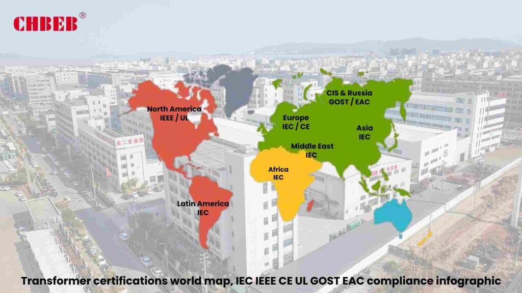
How to Understand International Certifications for Global Projects
- IEC 600765: The global standard for power transformers.
- IEEE/ANSI C57: What North America needs.
- CE marking: Required for access to the EU market.
- UL: Common for safety compliance for dry types.
- GOST/EAC: Russia and the CIS are in line with each other.
- ISO 9001/14001/45001: Management of quality, the environment, and health and safety at work.
Tip: Before buying, make sure you know the requirements for utility interconnection and witness testing.
When and why to choose a custom transformer
- Special voltages and vector groups: hybrid systems, phase shifts, and neutral needs.
- Better cooling: ONAF/ODAF during hot weather or when the load is too high for a short time.
- Compact enclosures: Pads or retrofits that take up less space.
- Noise reduction: Low-flux cores, dampening, and acoustic screens for hospitals and cities.
- Marine/C5-M protective coatings and sealed bushings for coastal and industrial areas.
- Digital monitoring: RTDs, moisture, dissolved gas, and gateways for planned maintenance.
Conclusion
When selecting an 11kV–35kV step-up transformer, price alone should never be the deciding factor. A truly reliable investment requires looking at the full picture.
Define your needs clearly: Match kVA to actual and future load, allow 15–25% growth margin, and account for harmonics or special duty cycles. This prevents both oversizing and costly failures from undersizing.
Evaluate materials wisely: Copper costs more up front but ensures lower losses, stronger fault tolerance, and longer service life. Aluminum may be suitable for budget-sensitive or temporary projects, but often results in higher lifetime costs.
Calculate the Total Cost of Ownership (TCO): Consider equipment price, civil works, energy losses over 20–30 years, maintenance, downtime risk, and residual value. Often, a slightly higher initial investment pays back many times in savings and reliability.
Check certifications and customization: Ensure compliance with IEC, IEEE/ANSI, CE, or local standards, and tailor features such as cooling, insulation, vector groups, coatings, and monitoring to your site conditions.
In short: Choosing the right step-up transformer is about more than buying hardware. It’s about securing safe interconnection, efficient performance, and the lowest lifetime cost for your project. By combining accurate sizing, material selection, TCO analysis, and compliance checks, you gain not just a transformer, but a long-term guarantee of stability and value.
- Apparent Power and Power Factor — All About Circuits ↩︎
- Transformer types — Wikipedia ↩︎
- Comparison of Copper and Aluminum in Transformers — ScienceDirect ↩︎
- Total Cost of Ownership in Electrical Distribution — Schneider Electric ↩︎
- IEC 60076 Power Transformer Standards — IEC ↩︎
Learn More
Want to explore more transformer solutions? Download our latest product catalog or browse our product categories to find the right fit for your project.

Introduction
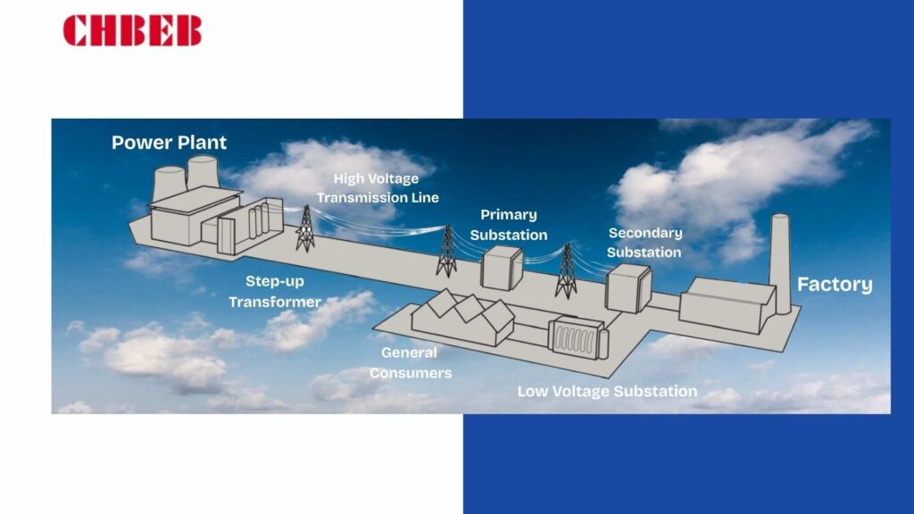
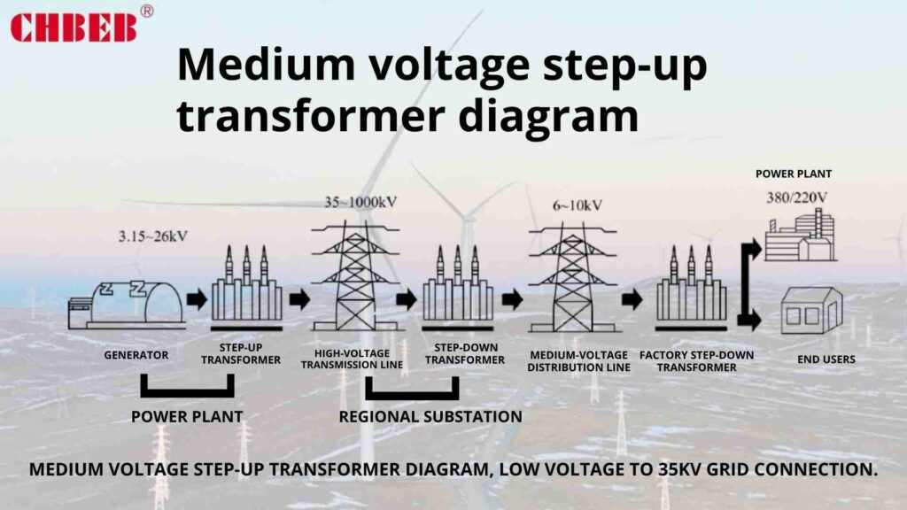
A lot of the time, projects fail when they make power at low voltage but send it in a way that isn’t very efficient. Losses, instability, and downtime get worse. Medium-voltage step-up transformers1 remedy this by raising the output to 11–35kV, which makes sure that the grid is safe, efficient, and reliable.
What is an MV Step-Up Transformer? Understanding the Basics
Not knowing how MV step-up transformers work can lead to design mistakes, wrong sizes, and greater prices. You can avoid expensive mistakes and choose equipment that satisfies both utility and project objectives by clearly stating its purpose and principles.
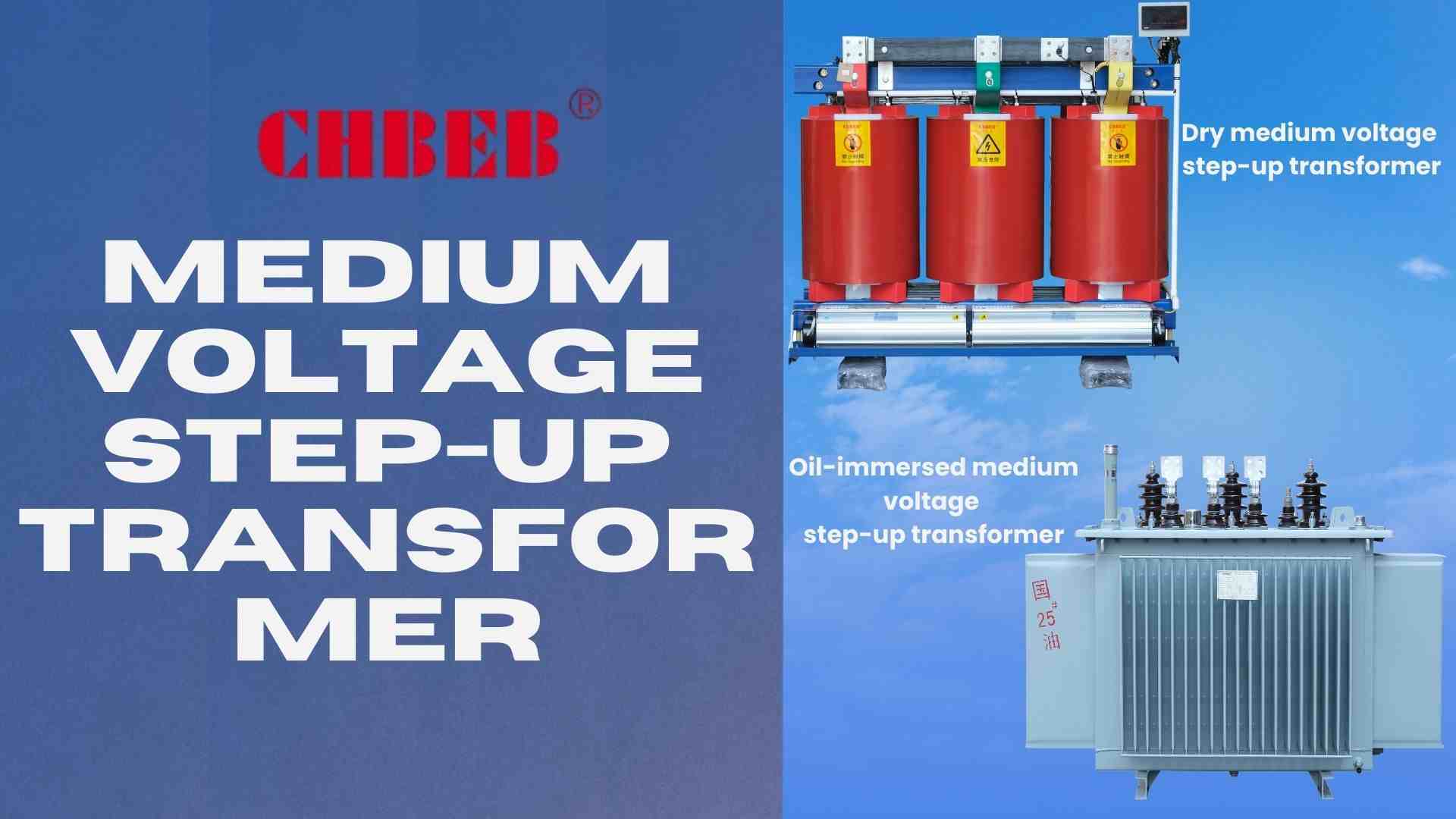
What it is and what it does
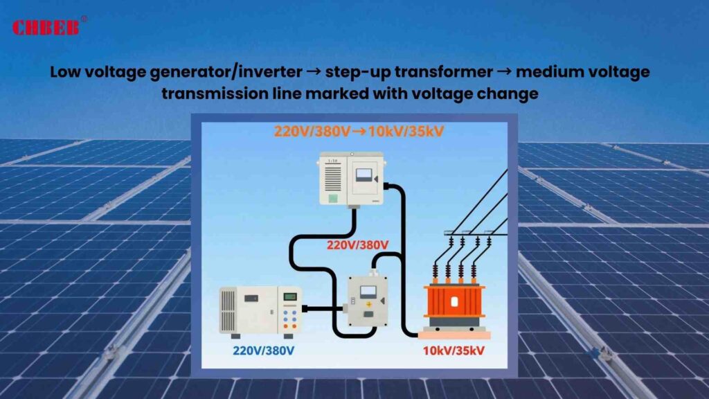
A medium-voltage (MV) step-up transformer is an electrical device that raises the output of a generator or inverter (usually 400V–1kV) to medium-voltage levels of 11kV, 22kV, or 35kV. This height slows down the flow of current, which makes it easier to send power over long distances and connect to the grid in a way that is safe.
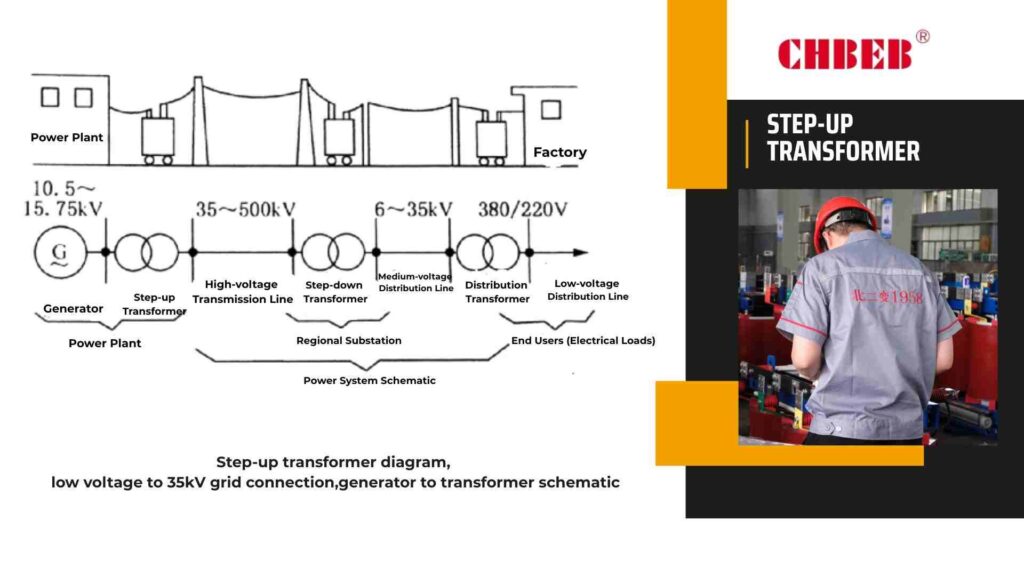
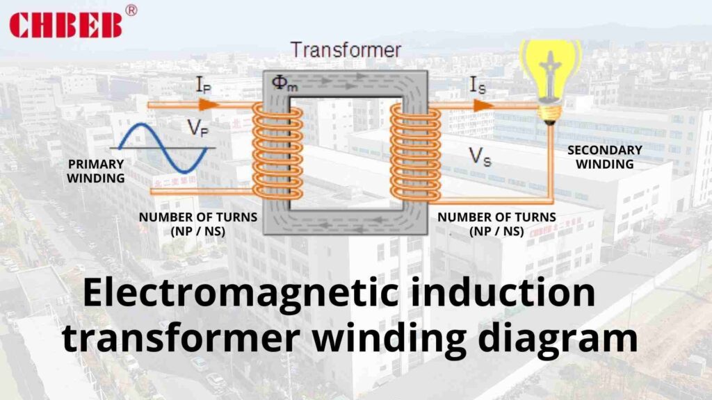
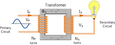
How electromagnetic induction works: the science behind it
Electromagnetic induction2 is what MV step-up transformers use. The primary winding, which is coupled to the low-voltage output, causes magnetic flux to flow through the laminated steel core. This flux makes the voltage in the secondary winding higher, which is proportional to the turns ratio. This makes it possible to transfer energy efficiently with minimal losses.
Why it’s important to raise the voltage in 11kV-35kV grids
If you don’t use the correct step-up transformer, you could lose a lot of power, have an unreliable supply, and not meet your obligations. By raising the voltage to between 11 and 35 kV, projects may send power more efficiently, integrate renewable energy sources, and keep the grid stable for a long time.
Getting the most out of your power by losing as little as possible
Low-voltage transmission needs a lot of current, which creates heat and energy losses. Step-up transformers raise the voltage, which lowers the current and I²R losses3. This optimization makes sure that power flows smoothly, cuts costs, and increases the return on investment for big projects.
Important Part of Bringing Together Renewable Energy4
Solar and wind energy sources, for example, work at low voltages that aren’t good for direct grid injection. MV step-up transformers raise these outputs to 11–35kV, making them function with utility networks and allowing sustainable energy to spread to national grids.
Specific Uses and Real-Life Situations
Theory seems abstract without real-world examples. MV step-up transformers have a direct effect on performance, cost, and compliance in many industries and energy projects.
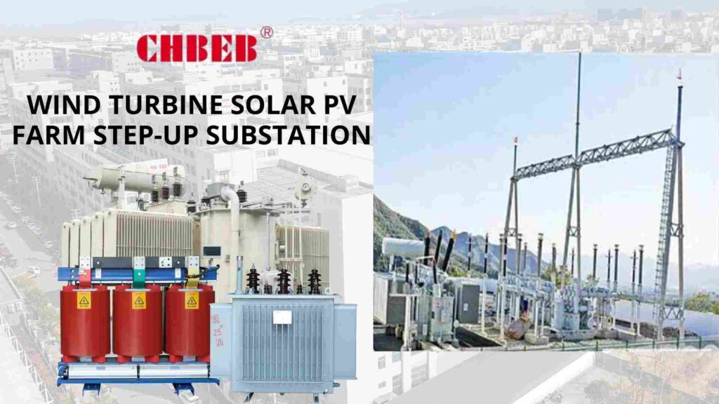
Case Study 1: Wind and Solar Farms
Wind turbines usually make 690V of electricity, whereas utility-scale solar farms make 400–800V5. MV step-up transformers boost these outputs to collection networks with voltages between 22 and 35 kV. This makes renewables ready for the grid, cuts down on the size of collector cables, and makes sure that interconnection regulations are met.
Case Study 2: Grids for Businesses and Factories
Big factories, mines, and data centers need electricity that is steady and works well. MV step-up transformers connect on-site generation or backup systems to distribution feeders that range from 11 to 33 kV. This makes sure that the system works reliably, cuts down on energy waste, and makes it easier to increase as demand for power grows.
Conclusion
Medium-voltage (MV) step-up transformers are more than just electrical equipment — they are the bridge between generation and the grid. By raising voltage from 400–1000 V to 11–35 kV, they cut transmission losses, improve stability, and ensure compliance with utility standards.
For professionals
Correct specification of kVA rating, impedance, vector group, and cooling class ensures that projects avoid costly redesigns, pass grid-code checks, and operate efficiently for decades. These units are essential for wind and solar farms, industrial cogeneration, and large-scale commercial loads that require reliable interconnection.
For beginners
Think of an MV step-up transformer like a highway on-ramp. A generator produces “local street” power at low voltage, but without the transformer it cannot travel long distances efficiently. The step-up transformer boosts it to “highway speed” (11–35 kV), so electricity can flow smoothly, safely, and economically to the wider grid.
In short: Whether for a wind farm, solar park, factory, or data center, choosing the right MV step-up transformer means lower losses, safer integration, and long-term reliability. It is a cornerstone of building efficient, stable, and future-ready power systems.
- :Transformer (Step-up and Step-down) — Wikipedia ↩︎
- Electromagnetic Induction — All About Circuits ↩︎
- Transformer Losses Explained — EEVblog ↩︎
- Renewable Energy Grid Integration — IEEE Xplore ↩︎
- Wind and Solar Farm Electrical Systems — ScienceDirect ↩︎
Learn More
Want to explore more transformer solutions? Download our latest product catalog or browse our product categories to find the right fit for your project.

Introduction
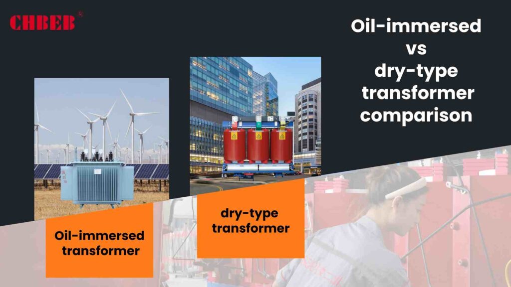
If you pick the wrong transformer, you could put your safety at danger, have downtime, and waste money. Conflicting claims make things even more confusing. This article clears up any confusion about dry-type and oil-immersed designs, compares them fairly, and illustrates how to choose the best unit for performance, compliance, and total cost of ownership.
The main point of the comparison is the basic differences.
Not understanding the basics leads to wrong specs, hot spots, and rework. If you don’t keep an eye on them, projects will go over budget and schedule. The first step is to explain how cooling and insulation materials work. This is the basis for safety, sizing, installation limits, and lifespan cost.
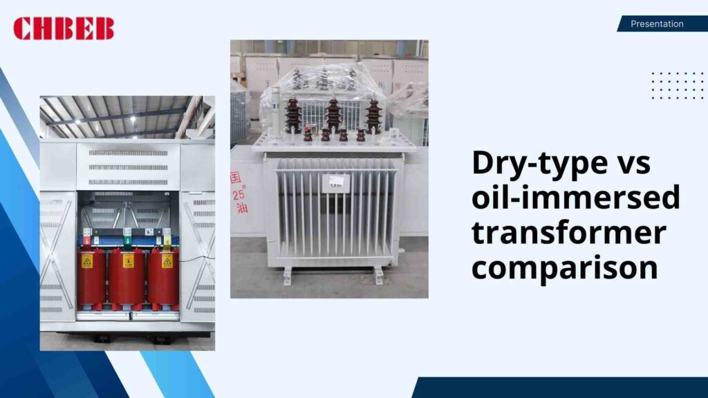
What are the Cooling and Insulation Mediums?
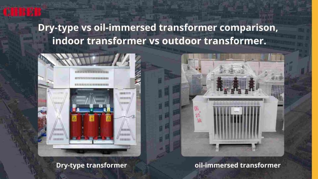
Dry-type1: The windings and core are cooled by air and insulated with solid materials like VPI/VPE varnish or cast-resin epoxy. There is no liquid dielectric present, therefore heat departs by natural or forced air. Good for inside locations, areas where liquids can’t get in, and quick installation with no requirement for containment.
Oil-immersed2: The windings and core are in a sealed tank full of dielectric fluid, which can be mineral oil or natural ester. Oil circulation (ONAN/ONAF3) moves heat from the tank to the radiators. Great thermal inertia, small size, and high overload capacity make this perfect for outdoor use or in substations.
At a Glance: A Side-by-Side Comparison Table
| Attribute | Dry-Type (VPI/Cast-Resin) | Oil-Immersed (Mineral/Ester) |
|---|---|---|
| Cooling & Dielectric | Air cooling; solid insulation; no liquid | Oil/ester cooling; fluid dielectric; sealed tank |
| Fire Behavior | No liquid; low fire load; smoke possible under fault | Mineral oil: lower fire point; ester: higher fire point, self-extinguishing tendency |
| Location Fit | Indoor, basements, hospitals, malls, tunnels | Outdoor yards, pad-mounts, utility stations |
| Maintenance | Low; no oil sampling; periodic cleaning | Oil testing, gasket checks, radiator cleaning |
| Thermal/Overload Margin | Moderate; sensitive to dust/ventilation | High; excellent heat dissipation/inertia |
| Efficiency & Losses | High; slightly higher losses at large ratings | Very high; typically lower losses for big units |
| Footprint & Weight | Larger footprint for the same kVA | More compact for the same kVA |
| Environmental Risk | No liquid spill risk | Mineral oil spill risk; ester mitigates impact |
| Noise | Good with damping; room acoustics matter | Good; tank/radiators radiate sound outdoors |
| Capex (typical) | Higher per kVA at larger sizes | Lower per kVA for MV/HV ratings |
Important Things to Think About When Making a Decision
It doesn’t work to buy based only on pricing. Safety, the environment, efficiency, and lifespan are all hidden factors that determine genuine worth. Before you commit, use these criteria to weigh risk, compliance, and performance.
Safety and Effects on the Environment
- Fire safety: Dry-type doesn’t use liquid fuel, and cast-resin doesn’t let flames spread. Esters are safer than mineral oil in locations where people are present since they have high fire points and break down naturally.
- Risk of spills: Dry-type doesn’t have any way to contain spills; oil units need bunds and spill plans. Esters make it easier to get permits in sensitive areas and lower the risk to the environment.
- Ingress and contamination: Dry-type needs clean airflow; dust and humidity break down insulation over time. Sealed oil tanks don’t let airborne contaminants in, but they do need to have their fluids checked regularly.
- Safety for workers and arcs: Both need interlocks, clearances, grounding, and PPE. Dry-type can make it easier to construct indoor exits and ventilation.
Cost: Upfront Cost vs. Total Cost of Ownership (TCO)4
- Capex: Dry-type designs tend to cost more per kVA at medium and large levels, while oil designs use small tanks and known manufacturing scales.
- Opex (losses): Oil units frequently win at high kVA with reduced no-load/load losses. Over the course of 20 years, modest gaps in efficiency add up to big energy bills.
- Dry-type maintenance: cleaning and IR examinations; few parts. Oil: sample fluids, gaskets, and radiator maintenance—things that happen over and over again.
- Civil and compliance: Dry-type may lower the expense of fire protection and containment within. Compared to mineral oil, oil esters can offset civil measures.
How well it works, how much weight it can hold, and how long it lasts
- Thermal performance: The thermal mass of oil makes it possible to handle overloads and changes in temperature. Dry-type needs appropriate ventilation and a variety of loads to work well.
- Efficiency: The differences get smaller as kVA gets smaller; oil usually wins out as kVA gets bigger.
- Both can last more than 20 to 30 years if they are taken care of properly. Cooling oil can extend the life of insulation under intense cyclic use, and dry-type avoids phenomena that cause liquids to age.
- Harsh sites: Oil with coatings works well in coastal and desert regions, whereas dry-type works best where liquids are limited (hospitals, tunnels, high-rises).
How to Pick the Right Transformer for Your Needs
Every site has its own set of rules. Ignoring them leads to expensive compromises. Map out your role, environment, and compliance to technology fit, then check your option against studies and vendor data to be sure it will last.
Best Uses for Each Type
- When the transformer is within or underground, liquids are limited, there are a lot of people walking around, it needs to be installed quickly, it has a moderate kVA, and fire rules are very rigorous, choose Dry-Type. Common places include hospitals, malls, schools, data-room adjacency, tunnels, and high-rises.
- Choose Oil-Immersed when: you have a yard or pad outside, a high kVA/MVA, a cyclic or heavy motor duty, tight footprints, and want to minimize losses. Common places include utility substations, factories, places where renewable energy is collected, and college campuses.
- Think for Natural Ester fluids if you want oil but want to keep the risk of fire and pollution low. This is especially important in transit hubs, congested urban campuses, and heritage districts.
Checklist for the Final Decision
- Duty profile: kVA that stays the same, ramps, motor starters, harmonics, and overload expectations.
- Location issues: indoors or outside, clearances, ventilation, noise, and access.
- Safety and codes: building and utility requirements, fire plans, and containment needs.
- Goals for efficiency: Make money off of assured losses over the life of the project; compare TCO.
- Environment: altitude/ambient, dust, humidity, and exposure to the seashore or chemicals.
- Ability to maintain: testing oil in-house vs. wanting something that doesn’t need much upkeep.
- Footprint and logistics: weight limitations, pad design, and access for transport and cranes.
- Future growth: more capacity, running in parallel, modularity, and an upgrade path.
- Vendor support: testing, documentation, spare parts, warranty, and response times.
Conclusion
Conclusion
When comparing dry-type and oil-immersed transformers, it’s not enough to look only at the purchase price.
For professionals
Oil-immersed units usually offer higher efficiency, better thermal margins, and a smaller footprint, making them ideal for large kVA outdoor projects such as substations, factories, and renewable energy plants. Dry-type units, by contrast, excel in indoor safety, fire resistance, and reduced maintenance, making them suitable for hospitals, malls, tunnels, and high-rise buildings. The right choice should balance kVA rating, cooling, fire codes, environmental risks, and the Total Cost of Ownership (TCO) over 20–30 years.
For beginners
Think of it this way: an oil-immersed transformer is like a powerful engine cooled with liquid — compact, efficient, and strong, but requiring regular “oil checks” and maintenance. A dry-type transformer is more like an electric motor cooled by air — larger in size, safer indoors, and easier to maintain, but usually more costly. Both can last decades if used in the right place.
In short: Dry-type focuses on safety and indoor convenience, while oil-immersed offers efficiency and strength for large-scale outdoor duty. By considering not just price but also safety rules, environment, and lifetime operating costs, you can choose the transformer that delivers the best balance of reliability, compliance, and long-term value.
- Dry-type transformer — Wikipedia ↩︎
- Oil-Immersed Transformer Performance — ScienceDirect ↩︎
- Transformer Cooling Methods — All About Circuits ↩︎
- Total Cost of Ownership in Electrical Distribution — Schneider Electric ↩︎
Learn More
Want to explore more transformer solutions? Download our latest product catalog or browse our product categories to find the right option for your project.
Introduction
It can be hard to figure out how much to spend on an electrical transformer box1. If you don’t know how much something will cost, you can pay too much or make a deal that isn’t safe. You can plan better and avoid costly mistakes if you know the capacity ranges, main price drivers, and lifetime costs.
Part 1: What is the price of an electrical transformer box?
Just looking at the sticker price can be misleading. People who want to buy typically simply look at the price up front and not the specs. This leads to either the improper size or a budget that is too low. You can get a realistic picture of an investment by looking at pricing ranges and the things that affect cost.
Price Ranges Based on kVA Capacity
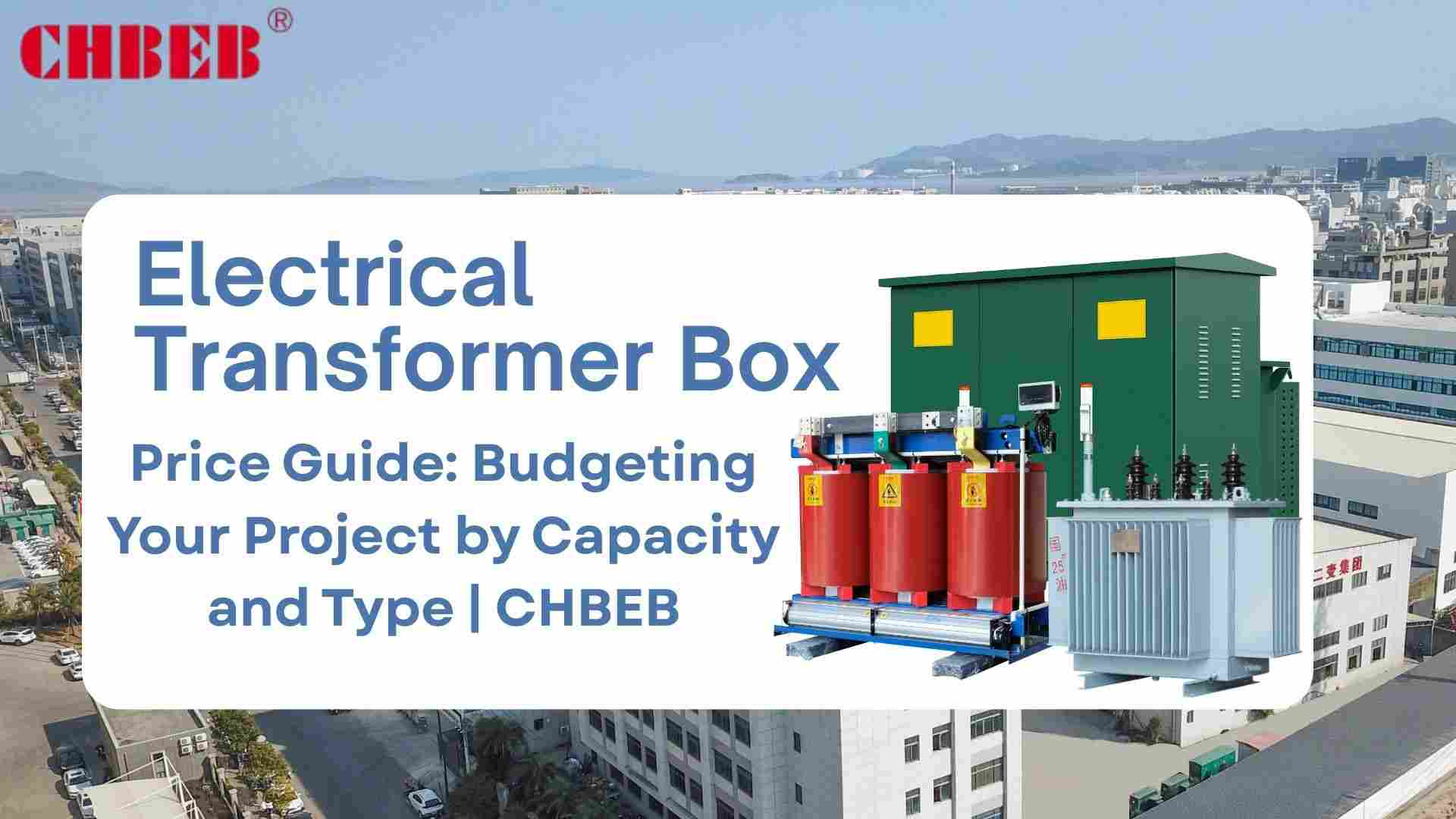
The price of a transformer box goes up with kVA, although not in a straight line. The price depends on the design complexity, voltage class, and configuration. The ranges below are for standard pole-mounted or pad-mounted2 devices (USD).
- $3,000 to $9,000 for 50 to 200 kVA (home and light business)
- $12,000 to $35,000 for 500 to 1,000 kVA (small industrial or office parks)
- $55,000 to $200,000 or more for 2,000 to 5,000 kVA (factories, data centers, renewables)
Please note that the ranges do not include shipment, installation, or site work. Always check with the supplier’s quotes.
Important Things That Affect Box Prices
- Capacity (kVA): Bigger cores, windings, and tanks cost more.
- Type: Secure enclosures that are mounted on pads usually cost more than those that are mounted on poles.
- ONAN vs. ONAF3 adds fans and controls to the cooling process, whereas dry-type makes it bigger and uses more materials.
- Winding material: Copper is more expensive than aluminum, but it lasts longer.
- Insulation and enclosure: Ester fluids, stainless steel cabinets, or C5-M coatings make the price go up.
- Certifications: IEC, IEEE, and UL approvals add to the cost of testing and paperwork.
- Market conditions: Quotes are affected by the steel, copper, and logistics cycles.
Part 2: Outside the Box: Costs of Installation, Safety, and the Life Cycle
If you merely look at the box price, you miss out on big costs. A lot of the time, projects go over budget because they didn’t incorporate installation, compliance, or operating losses. You maintain long-term value by thinking about lifetime expenses.
Costs for installation and site preparation
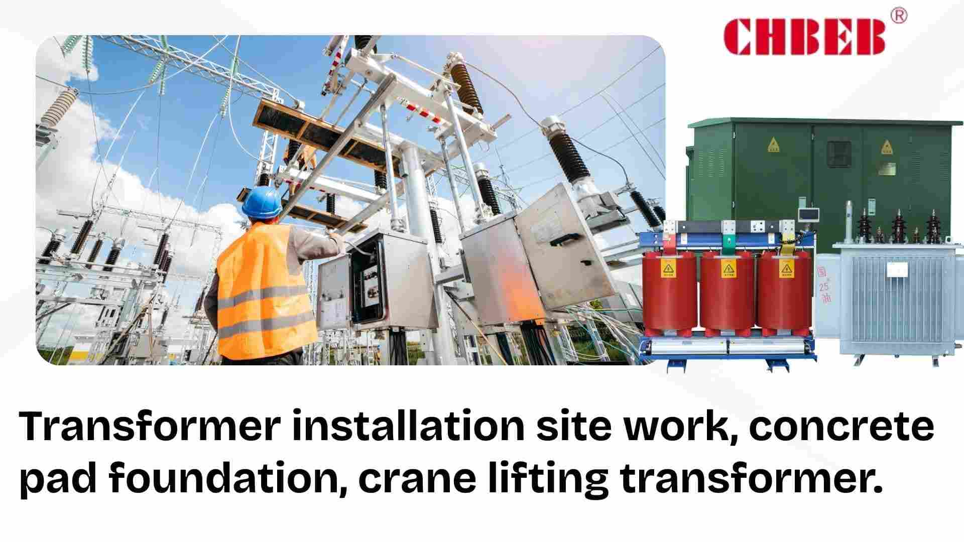
- Concrete slabs, drainage, and anchor bolts are used for pads and foundations.
- Moving and handling: freight, cranes, permits, and insurance.
- Labor: firing people, grounding, and commissioning tests.
- Fencing, access roads, and clearances are all things that need to be done before the site is ready.
Typical extras cost between $2,000 to $20,000 or more, depending on the size and difficulty of the site.
Costs for safety features and compliance
- Lockable cabinets and dead-front terminations for public safety.
- Wildlife guards and seals for the environment to make sure they work.
- Fuses and surge arresters to keep wires and windings safe.
- Control of noise in homes or other sensitive areas.
- Fees for testing and inspection to take utilities.
These features cost more up front, but they lower liability, downtime, and service calls.
The Total Cost of Ownership (TCO) Point of View
TCO = Capex + Installation + Energy Losses + Maintenance + Downtime − Residual Value
- Losses: An efficiency gap of 1–2% might cost thousands of dollars in energy per year.
- Maintenance: Easy access and standard parts lower the cost of service.
- Risk of downtime: Reliable units don’t have unanticipated outages or fines.
- Residual value: Boxes of higher quality keep their value or last longer.
Part 3: Making Smart Purchases: New vs. Used & Custom Options
If you only look at “new,” your budget may go up, and if you don’t customize, your fit may not be good. Balancing options makes sure that performance is good without wasting resources.
A Cost Comparison Between New and Used/Refurbished Transformers
- New: Most expensive up front; meets modern standards; comes with guarantees; lasts 20 to 30 years or more.
- Refurbished: Lower capital costs, shorter guarantees, a lifespan of 10 to 20 years, and excellent for backup or temporary use.
- Used as-is: Cheapest; most likely to fail; best for short-term or non-critical service.
When it makes sense to customize
- Electrical specs: To coordinate, use special vector groups, taps, or %Z.
- Environment: Coatings for the coast, sealed bushings, and cores that reduce noise.
- Compliance: criteria for each utility, type tests, and paperwork.
- Layout: Small footprints to make the most of limited area.
Customization generally lowers lifespan costs for big projects by minimizing rework and waste.
Conclusion
When planning for an electrical transformer box, it is not enough to look only at the price tag.
For professionals
- Specify capacity (kVA), cooling method (ONAN/ONAF or dry-type), winding material (copper/aluminum), insulation level, and compliance with IEC/IEEE/UL—these drive performance and long-term cost.
- Use a TCO view:
TCO = Capex + Installation + Losses + Maintenance + Downtime − Residual Value. Even a 1–2% efficiency gap can translate into thousands of dollars per year in energy costs.
For beginners
Think of a transformer box like buying a car: the sticker price is only the start.
Fuel (energy losses), maintenance, and resale value matter just as much.
A cheaper unit can cost more later through higher electricity bills, repairs, or outages.
A well-chosen box may cost a bit mor
- Distribution transformer — Wikipedia ↩︎
- Pad-mounted transformer — Wikipedia ↩︎
- Transformer Cooling Methods — All About Circuits ↩︎
Learn More
Want to explore more transformer solutions? Download our latest product catalog or browse our product categories to find the right option for your project.
Introduction
Are you having trouble with those green cabinets or metal cans on poles? When you don’t comprehend them, you make bad choices and put yourself in danger. This tutorial makes transformer boxes easy to understand, describes the different varieties and their parts, and teaches you how to stay safe and fix problems with confidence.
Part 1: The Basics of a Transformer Box
It can be strange to see power tools near homes, roadways, and worksites. People are afraid, change things, or make incorrect choices about where to put things since they don’t know what will happen. You will be able to plan better and work more safely if you know what a transformer box is and where each type goes.
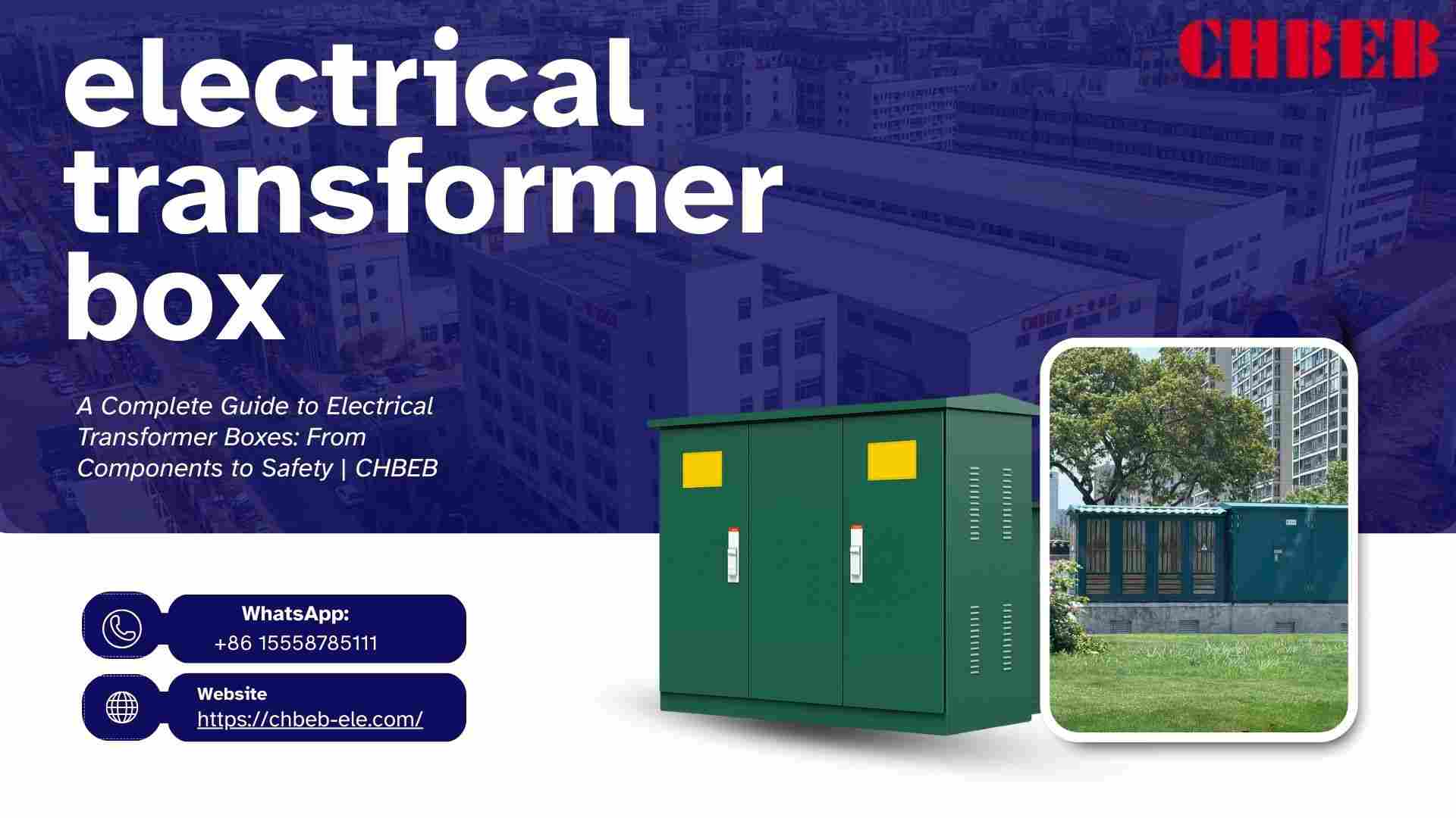
What Is a Transformer Box, Exactly?
A transformer box is a protective box that holds a distribution transformer1 and the parts that connect it. It raises or lowers the voltage between the utility’s medium-voltage network and local loads, while protecting energized sections from the weather, animals, and people. Boxes also help with cable routing, switching, fusing, and grounding.
The transformer tank, high- and low-voltage compartments, bushings or dead-front elbows, fuses, surge arresters, a tap changer, gauges, and a nameplate with a clear name are all common parts. The enclosure has doors that may be locked, drainage, and ventilation pathways. It can be placed on a pad or mounted on a pole.
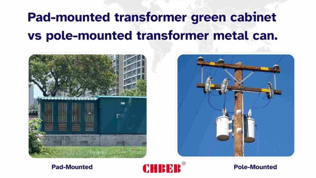
There are two main types: pad-mounted and pole-mounted.
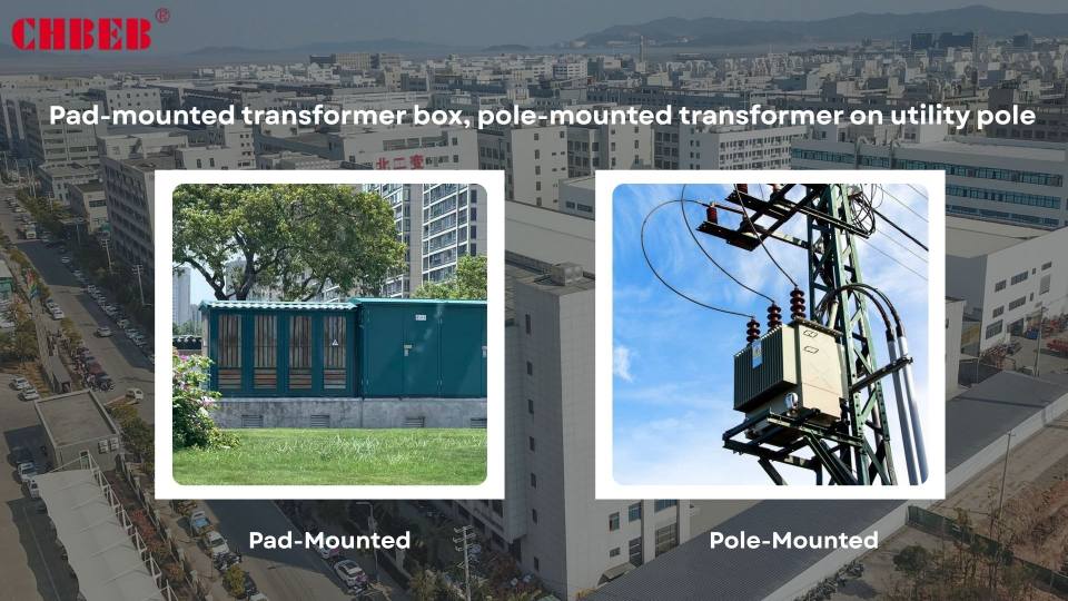
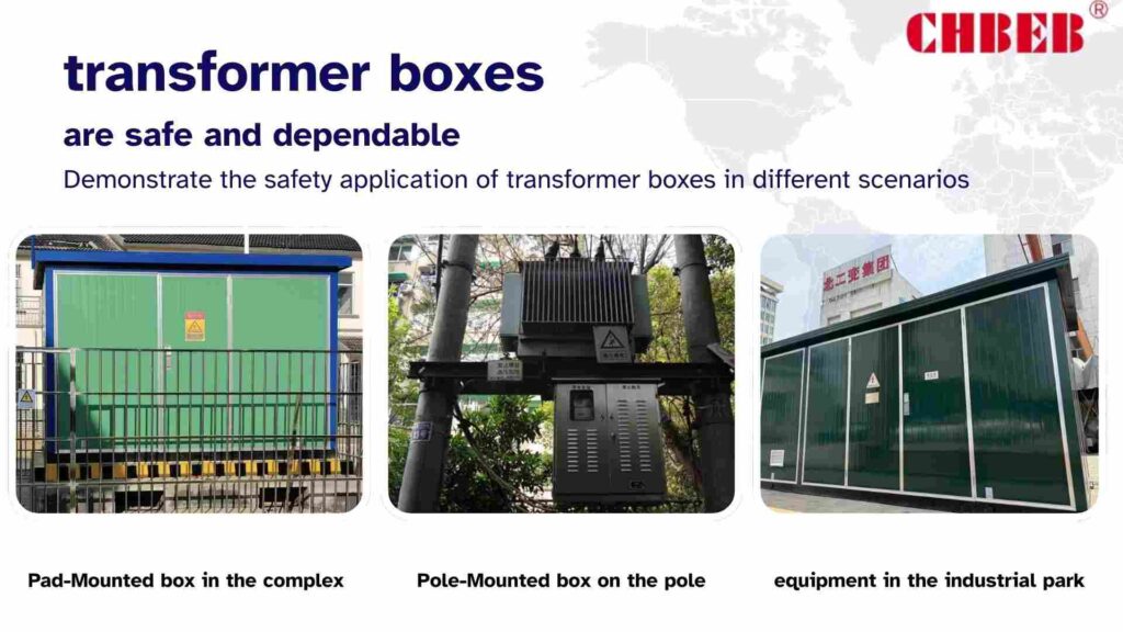
Inside a secured steel cabinet, pad-mounted equipment2 sit on the ground. They go well with subterranean cables, have dead-front terminations, and fit in with neighborhoods, campuses, retail parks, and industrial areas. Benefits include safety for the public, looks, and simple access for maintenance trucks.
The cylindrical “cans” on utility poles are called pole-mounted units3. They are cheap for lines in rural areas or places with overhead networks. Bucket trucks are used by crews to service them. They’re great for lengthy overhead feeders, but not so great when looks, noise sensitivity, or controlling public access are important.
Quick chooser: pad-mounted for underground feeders, public spaces, or multi-tenant campuses. Pole-mounted for long overhead runs or service areas with low density.
Part 2: Anatomy and Function: What’s in the Box?
Only seeing a locked door hides important information. That space makes room for lies and mistakes. You will be able to find problems sooner, define correctly, and avoid expensive rework or outages if you learn about each internal part and how it operates.
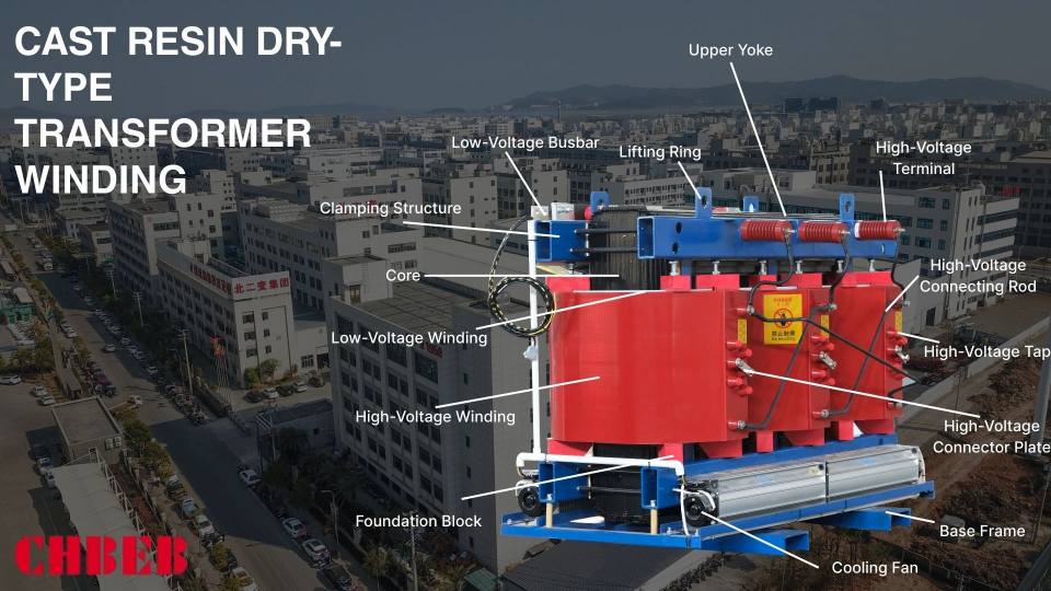
A Diagram and a Breakdown of Important Parts
- Core: Laminated steel (or amorphous metal) that guides magnetic flux well while keeping losses to a minimum.
- Windings: Copper or aluminum coils around the core. The turns ratio determines how much the voltage goes up or down.
- Insulation system: Papers, varnishes, and spacers that keep gaps open and stop partial discharge.
- Tank and fluid (if liquid-filled): Oil or natural ester that keeps heat in and insulates; a sealed tank controls expansion.
- Radiators and fans (ONAN and ONAF): Passive fins and optional fans help cool things down, which helps insulation last longer.
- Bushings and dead-front terminations are safe connections for MV/LV cables. Elbows let you break the load.
- Surge arresters: Stop lightning and switching surges by working with the transformer’s insulation level.
- Fuses (bayonet/current-limiting) stop faults and keep windings from getting seriously damaged.
- Tap changer: Changes the ratio to fine-tune the secondary voltage for changes in the season or the length of the feeder.
- Indicators and sensors: oil level and temperature, pressure and vacuum, and sometimes winding RTDs.
- Grounding network: connects the enclosure and creates a safe path for fault current. This is very important for public safety.
- Nameplate: The “passport” that shows kVA, voltages, impedance, losses, vector group, weight, and fluid type.
Tip for the diagram: Picture the outside cabinet going to the HV compartment with arresters and fuses, then to the transformer tank with the core and windings, then to the LV compartment with the bushings and cable lugs, and finally to the ground bus and labels.
Understanding Transformer Noise: The Science Behind the Hum
The constant “hum” isn’t a problem on its own. Magnetostriction4, which is when AC magnetizes steel and alters the size of the core, creates vibrations at twice the line frequency (100/120 Hz) and its harmonics. Bad mounting, loose hardware, or high flux density can make it worse.
Some ways to reduce noise are to use low-noise laminations, tighter clamping, dampening pads, and to be careful about where you put them so they aren’t near reflective walls. In regions that are sensitive, you should ask for low-noise cores, isolation mounts, and acoustic screens. A quick change in sound frequently means that the hardware is loose, the cooling isn’t working right, or the load is uneven.
Part 3: Safety, Upkeep, and Fixing Problems
It’s risky to mix public interest with work that needs to be done quickly. Without clear standards and regular treatment, small problems might turn into outages or injury. A short checklist for the public and experts eliminates accidents and keeps assets working for decades.
Important Safety Rules: A List for the Public and Professionals
For the public:
- Stay away from cabinets and apparatus that is mounted on poles; never sit, climb, or put things on them.
- Call in any damage, open doors, graffiti, or strange sounds or smells right away.
- Keep the area around vents free by not planting plants or stacking anything there.
- Before you dig, call. There may be subsurface lines that come out of pad-mounted boxes.
For people who work:
- Wear arc-rated PPE and follow lockout-tagout. Make sure there is no voltage before touching.
- Keep a safe distance and use insulated tools and test equipment that has been graded.
- Check the torque on the terminations and bus connections to make sure they are grounded and bonded.
- Check the paint, gaskets, hinges, and wildlife guards. Fix any rust early.
- Make that the surge arresters work with the transformer’s BIL5, and replace old arresters before they break.
- Keep an eye on loads and temperatures over time, and plan infrared scans to find hot spots.
- If you need to, test the insulating fluid every so often for moisture and dielectric strength. Fix any leaks right away.
- Keep maintenance logs to make it easier to find problems quickly; record tap position, %Z, and nameplate data.
When to Call an Expert and Common Problems
- Too hot: fans not working (ONAF), air flow restricted, too much power, or too high of a temperature. Action: Bring back the cooling, balance the loads, and check the kVA margin.
- Oil leaks or stains: old gaskets or tiny cracks in the tank. Action: Separate, fix seals, check the level and condition of the fluid.
- Corrosion: Rusting happens faster in coastal and arid areas. Action: Recoat; use higher-quality coatings and sealed bushings.
- Nuisance fuse operations: faults downstream or wrong ratings. Action: Check the circuits and make sure the coordination study is correct.
- Noise or vibration that isn’t normal could be caused by loose clamps, resonance, or an imbalanced load. Action: Make the hardware tighter, add dampening, and adjust the phases.
- Voltage sag or unbalance can happen because of undersized conductors, bad connections, or the improper tap. Action: Fix the terminations, change the taps, and check the size of the conductors.
- Animal and wildlife entry: Squirrels, birds, or snakes getting in. Action: Put up wildlife guards and close off all openings.
- Water getting in or condensation: seals that are broken or breathers that are blocked. Action: Reseal, service the breathers, and change the desiccants.
If you notice open doors, burning smells, arcing, fluid pooling, or repeated protective actions, call an expert right away. Don’t turn it back on until a qualified technician looks into it and fixes it.
Conclusion
When chosen, installed, and maintained correctly, transformer boxes are both safe and reliable.
For professionals
A well-specified box with the right insulation level, surge protection, grounding, and cooling ensures long-term compliance and stability. Regular inspections of oil, gaskets, arresters, and load balance help prevent costly downtime. Logs and infrared scans give early warnings before failures happen.
For beginners
In simple terms, a transformer box is like a protective shell around the “heart” of the power system. If you stay away from it, report damage or strange noises, and let qualified technicians handle problems, it will quietly keep homes, schools, and factories supplied with safe power.
As Nikola Tesla once said, “Power is nothing without control.” In the same way, transformer boxes give shape, safety, and control to the flow of electricity.
In short: Know the type, understand the key parts, follow safety rules, and act quickly when you see signs of trouble. With these habits, transformer boxes will power communities safely and reliably for decades.
And remember: behind every “green cabinet” or “pole can” is a system designed to protect lives and property. Respecting it, maintaining it, and responding quickly to issues is the best way to ensure lower risks, fewer outages, and a stronger grid for the future.
- Distribution transformer — Wikipedia ↩︎
- Pad-mounted transforme ↩︎
- Pole-Mounted Transformer Basics — EEVblog ↩︎
- What Causes Transformer Hum — All About Circuits ↩︎
- Transformer Insulation and BIL — IEEE Xplore ↩︎
Learn More
Want to explore more transformer solutions? Download our latest product catalog or browse our product categories to find the right fit for your project.
Introduction
Power projects often fail when generators make low voltage that can’t move quickly. This leads to more losses, delivery that isn’t always reliable, and fines. A medium voltage step-up transformer fixes this by raising the voltage to 11–35kV, which makes sure that the transmission is safe and meets grid standards.

What is a Medium Voltage Step-Up Transformer, and what are the basics?
People who don’t understand what something is or how it works often size it inaccurately or use it wrong. These blunders cost money and make things less efficient. Buyers need to know the essentials so they know exactly what the transformer performs and why it’s important.
A Simple Explanation
A medium voltage step-up transformer1 is an electrical device that takes low-voltage power sources, like generators or inverters that run at 400 to 1000 volts, and elevates the voltage to medium voltages like 11kV, 22kV, or 35kV. It helps connect to the grid by increasing voltage and lowering current, which makes transmission more efficient.
The Core Principle: How It Raises the Voltage
Electromagnetic induction2 is what makes step-up transformers work. The generator is connected to the primary windings, and the secondary windings have more turns, which makes the voltage higher. This procedure lowers the flow of current, which cuts down on line losses and lets power transfer safely across networks.
The Important Role: Why These Transformers Are Necessary in 11kV–35kV Grids
If you skip the correct transformer, you could lose a lot of money, have systems that don’t work right, and have supply that isn’t reliable. Renewable initiatives can’t connect successfully without the right tools. To cut down on waste, connect renewables, and keep the grid stable, step-up transformers are very important.
Getting the most out of your power and cutting down on waste
When you send electricity at a low voltage, it makes too much current, which makes heat and wastes energy. This lowers profits and puts stress on the equipment. Step-up transformers enhance voltage, lower current, and eliminate losses, which makes equipment last longer and work better.
Putting renewable energy into the grid
Solar and wind farms generally produce power at 400–800V, which can’t be sent directly. This power stays stuck without step-up transformers. Transformers make renewable3 energy grid-compatible by raising the output to 11–35kV, which lets projects grow quickly.
Making sure the grid is stable and reliable
Voltage that isn’t stable can hurt sensitive equipment and cause outages. Not having enough of something also breaks the rules. Step-up transformers keep the output stable, balance the flow of power, and help with grounding and harmonics management, making sure safe and reliable operation.
Important Technical Features and Real-World Uses
Not following specs can lead to problems and waste time. Projects run over budget and have downtime when people don’t know what they’re doing. Knowing the most important characteristics and uses helps you make better investments and have long-term success.
Common Uses: Power Plants and Factories
- Power Plants: Raise the voltage of the generator to medium levels so it can be sent.
- Solar and wind farms: Connect renewable energy sources to the grid at the right voltages.
- Industrial Facilities: Provide a steady supply of power to big motors and machines.
- CHP plants: Help cogeneration systems use energy more efficiently.
- Battery storage systems let power flow in both directions and supply it steadily.
Anatomy of a Medium Voltage Transformer: Important Parts Explained
- Core: Laminated steel or amorphous material guides magnetic flux very well.
- Windings: Copper or aluminum wires increase voltage through turns ratio.
- Insulation: Stops short circuits and can handle a lot of electrical stress.
- Bushings: Make it safe to connect HV and LV circuits from the outside.
- Tap Changer: Changes the voltage ratio based on the time of year or the load.
- ONAN/ONAF options for the cooling system keep things cool and make them last longer.
- Tank/Enclosure: Keeps the inside parts safe; filled with oil or resin, depending on the type.
Conclusion
A medium voltage step-up transformer is not just another piece of hardware — it is the bridge that makes modern power projects possible.
For professionals
- Elevates generator or inverter output (typically 400–1000V) to medium-voltage levels (11–35kV).
- Reduces current flow, minimizes line losses, and ensures compliance with utility grid codes.
- Provides voltage regulation, fault isolation, grounding, and harmonic mitigation.
- Directly influences system reliability, asset lifespan, and compliance with IEC/IEEE standards.
For beginners
In simple terms, think of electricity like water. Low voltage is like water flowing in a small pipe — it can’t go far and wastes energy. The step-up transformer makes the “pipe” bigger by raising the voltage, so power can travel long distances without overheating or being lost. This is why solar farms, wind projects, and factories all need step-up transformers before they can safely send power into the grid.
Applications
From power plants and renewable energy projects to industrial sites and battery storage, these transformers are the “gateway” to reliable grid connection. Without them, energy would be stuck at the source, unable to move efficiently or meet utility standards.
Economic impact
By cutting losses and stabilizing output, step-up transformers lower lifetime operating costs and reduce unplanned downtime. The right design choice directly affects project ROI, grid stability, and even regulatory approval.
In short: A medium voltage step-up transformer ensures electricity is delivered efficiently, safely, and reliably. It turns raw power into usable grid power — protecting equipment, lowering costs, and enabling the growth of renewable energy worldwide.
- Transformer — Wikipedia ↩︎
- Electromagnetic induction ↩︎
- Renewable Energy Grid Integration — IEEE Xplore ↩︎
Learn More
Want to explore more transformer solutions? Download our latest product catalog or browse our product categories to find the right fit for your project.
