Dry Type Transformer Losses Explained: Iron, Copper, and Stray Loss Reduction Techniques?

Are you struggling to optimize the efficiency of your dry type transformers? You’re not alone. Many engineers and facility managers grapple with the challenge of minimizing transformer losses, which can significantly impact energy costs and system performance. But what if you could understand and reduce these losses, leading to substantial savings and improved reliability?

Dry-type transformer losses include iron loss (core), copper loss (windings), and stray losses. Engineers can reduce these through better core materials, optimized winding design, and electromagnetic shielding. This guide breaks down loss types and proven techniques for improving transformer efficiency in industrial and utility applications. Understanding and minimizing these losses is crucial for optimizing energy efficiency and reducing operational costs in power distribution systems.

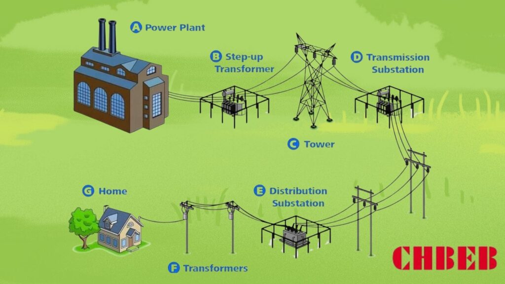
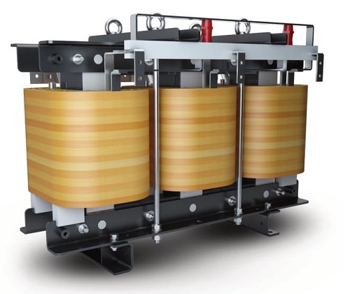
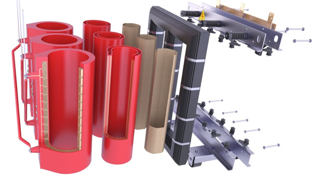
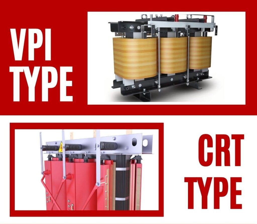
Diagram illustrating different types of losses in a dry type transformer
Dry Type Transformer Losses Diagram

In this comprehensive guide, I’ll walk you through the intricacies of dry type transformer losses, their causes, and most importantly, how to reduce them. We’ll explore iron, copper, and stray losses, examine case studies from top brands, and provide a practical checklist for loss reduction. Whether you’re a seasoned engineer or a facility manager, this article will provide valuable insights to help you make informed decisions about transformer efficiency.

Why Losses Matter in Dry Type Transformers: Energy, Heat, and Cost Implications?

Have you ever wondered why your transformers heat up or why your energy bills are higher than expected? The answer often lies in transformer losses. But why exactly are these losses so crucial, and how do they affect your bottom line?

Losses in dry type transformers are critical because they directly impact energy efficiency, heat generation, and operational costs. These losses convert valuable electrical energy into wasted heat, reducing overall system efficiency. Higher losses lead to increased cooling requirements, shorter transformer lifespan, and higher electricity bills. Understanding and minimizing these losses is essential for optimizing transformer performance, reducing energy consumption, and lowering long-term operational expenses.

Graph showing the relationship between transformer losses and energy costs
Transformer Losses vs Energy Costs

Exploring the Impact of Transformer Losses

Let’s break down the key implications of transformer losses:

  1. Energy Efficiency Reduction
  2. Heat Generation and Cooling Needs
  3. Operational Cost Increase
  4. Environmental Impact
  5. Transformer Lifespan Reduction

Energy Efficiency Reduction

How losses affect overall efficiency:

  • Direct conversion of electrical energy to heat
  • Decreased power output for a given input
  • Cumulative effect in large-scale power systems

I recently analyzed a manufacturing plant where transformer losses accounted for 2% of total energy consumption, highlighting the significant impact on overall efficiency.

Heat Generation and Cooling Needs

The thermal consequences of losses:

  • Increased internal temperature of transformers
  • Need for additional cooling systems
  • Potential for thermal runaway in extreme cases

During a recent facility upgrade, we found that reducing transformer losses by 20% allowed for a downsizing of the cooling system, resulting in substantial cost savings.

Operational Cost Increase

The financial impact of losses:

  • Higher electricity bills due to wasted energy
  • Increased maintenance costs for cooling systems
  • Potential for premature equipment replacement

Here’s a simplified view of how losses affect costs:

Loss Reduction Annual Energy Savings Cooling Cost Reduction Lifespan Increase
10% $5,000 – $10,000 5-10% 1-2 years
20% $10,000 – $20,000 10-15% 2-3 years
30% $20,000 – $30,000 15-20% 3-5 years

Note: Figures are illustrative and can vary based on specific circumstances.

Environmental Impact

The broader consequences of inefficiency:

  • Increased carbon footprint due to higher energy consumption
  • Greater strain on power generation resources
  • Contribution to overall grid inefficiency

Transformer Lifespan Reduction

How losses affect longevity:

  • Accelerated insulation degradation due to heat
  • Increased stress on components
  • Potential for premature failure

Key points about the importance of transformer losses:

  1. Losses directly impact energy efficiency and operational costs
  2. Heat generation from losses affects cooling requirements and lifespan
  3. Reducing losses can lead to significant long-term savings
  4. Environmental considerations are increasingly important
  5. Transformer longevity is closely tied to loss management

In my experience, many facility managers underestimate the long-term impact of transformer losses. I recall a project where replacing an old, inefficient transformer with a low-loss model resulted in energy savings that paid for the new unit within three years.

For instance, in a recent data center project, we focused on selecting transformers with exceptionally low losses. This decision was crucial because of the continuous high load in data centers. The result was a 15% reduction in overall energy costs and a significant decrease in cooling requirements, demonstrating the substantial impact of loss reduction in critical applications.

As we move on to discuss specific types of losses, keep in mind that understanding these implications is crucial for making informed decisions about transformer selection and maintenance. The energy, cost, and environmental impacts of losses underscore the importance of the technical details we’ll explore in the following sections.

Iron Loss Breakdown: How Core Design and Material Affect Efficiency?

Have you ever wondered why some transformers are more efficient than others, even when they’re not under load? The answer often lies in iron losses, also known as core losses. But what exactly causes these losses, and how can core design and material choice impact a transformer’s efficiency?

Iron losses in dry type transformers occur in the magnetic core and are present even when the transformer is not under load. These losses are primarily due to hysteresis and eddy currents in the core material. Core design factors like lamination thickness, stacking method, and joint design significantly affect iron losses. Material choice, such as using high-grade silicon steel or amorphous metals, can dramatically reduce these losses. Understanding and optimizing these factors is crucial for improving overall transformer efficiency.

Diagram showing different core designs and their impact on iron losses
Transformer Core Design Comparison

Analyzing Iron Losses in Transformer Cores

Let’s break down the key aspects of iron losses:

  1. Types of Iron Losses
  2. Core Material Selection
  3. Lamination Design
  4. Core Construction Techniques
  5. Impact of Operating Frequency

Types of Iron Losses

The two main components of iron losses:

  • Hysteresis losses: Energy lost in magnetizing and demagnetizing the core
  • Eddy current losses: Losses due to circulating currents in the core material

I recently analyzed a transformer where hysteresis losses accounted for about 60% of the total iron losses, with eddy current losses making up the remaining 40%.

Core Material Selection

How material choice affects losses:

  • Silicon steel: Common choice, varying grades available
  • Amorphous metals: Significantly lower losses but higher cost
  • Nanocrystalline materials: Emerging option for high-efficiency designs

During a recent project, switching from standard silicon steel to a high-grade variant reduced iron losses by 25%, demonstrating the significant impact of material selection.

Lamination Design

The role of core laminations:

  • Thinner laminations reduce eddy current losses
  • Insulation between laminations is crucial
  • Trade-off between loss reduction and manufacturing complexity

Here’s a simplified comparison of lamination thicknesses:

Lamination Thickness Relative Eddy Current Loss Manufacturing Complexity
0.35 mm 100% (baseline) Low
0.27 mm ~70% Medium
0.18 mm ~40% High

Core Construction Techniques

Methods to minimize losses:

  • Step-lap joints to reduce flux leakage
  • Mitred corners for better flux distribution
  • Grain-oriented steel for improved magnetic properties

Impact of Operating Frequency

How frequency affects iron losses:

  • Higher frequencies increase both hysteresis and eddy current losses
  • Particularly important in high-frequency applications
  • Necessitates special core designs for non-standard frequencies

Key points about iron losses in transformer cores:

  1. Hysteresis and eddy currents are the main sources of iron losses
  2. Core material selection significantly impacts efficiency
  3. Lamination design is crucial for reducing eddy current losses
  4. Construction techniques can further minimize losses
  5. Operating frequency is a critical factor in loss calculations

In my experience, optimizing core design and material selection can lead to substantial improvements in transformer efficiency. I recall a case where redesigning the core of a medium-voltage distribution transformer using advanced lamination techniques and high-grade silicon steel reduced iron losses by over 30%, resulting in significant energy savings for the end-user.

For example, in a recent renewable energy project involving wind farm transformers, we focused heavily on minimizing iron losses. The variable nature of wind power meant that the transformers would often operate at partial loads, where iron losses dominate. By implementing a combination of amorphous metal cores and advanced step-lap joint designs, we achieved a remarkable 40% reduction in no-load losses compared to standard designs.

As we move on to discuss copper losses, keep in mind that while iron losses are constant regardless of load, they form a significant portion of a transformer’s total losses, especially in applications with variable or low load profiles. Understanding and minimizing these losses is crucial for designing high-efficiency transformers across various applications.

Copper Loss Explained: Load Conditions and Winding Optimization?

Have you ever noticed that transformers tend to heat up more under heavy loads? This phenomenon is primarily due to copper losses, but what exactly are these losses, and how can we minimize them to improve transformer efficiency?

Copper losses in dry type transformers occur in the windings and are proportional to the square of the current (I²R losses). These losses increase with load and are the primary source of heat generation under high load conditions. Factors affecting copper losses include conductor size, winding design, and operating temperature. Optimizing these elements through techniques like using larger conductors, advanced winding geometries, and effective cooling can significantly reduce copper losses, improving overall transformer efficiency and performance.

Graph showing the relationship between load and copper losses in transformers
Copper Losses vs Load Graph

Diving Deep into Copper Losses

Let’s explore the key aspects of copper losses:

  1. Nature of Copper Losses
  2. Load Dependency
  3. Winding Design Optimization
  4. Temperature Effects
  5. Balancing Copper and Iron Losses

Nature of Copper Losses

Understanding the basics:

  • Caused by electrical resistance in windings
  • Proportional to the square of the current (I²R)
  • Manifests as heat in the windings

I recently analyzed a transformer where copper losses at full load were nearly three times the iron losses, highlighting their significance in high-load operations.

Load Dependency

How load affects copper losses:

  • Losses increase quadratically with current
  • Minimal at no load, dominant at high loads
  • Critical factor in transformer sizing and efficiency

During a recent industrial project, we observed that copper losses increased by a factor of four when the load doubled, demonstrating the quadratic relationship.

Winding Design Optimization

Strategies to reduce copper losses:

  • Using larger conductor cross-sections
  • Employing parallel conductors
  • Optimizing winding geometry for heat dissipation

Here’s a simplified view of winding optimization techniques:

Technique Loss Reduction Cost Implication Best For
Larger Conductors 10-20% Moderate Increase High-load applications
Parallel Windings 5-15% Slight Increase Medium to large transformers
Foil Windings 10-25% Significant Increase Special applications

Temperature Effects

The impact of heat on copper losses:

  • Resistance increases with temperature
  • Creates a feedback loop of increasing losses
  • Emphasizes the importance of effective cooling

Balancing Copper and Iron Losses

The art of transformer design:

  • Optimizing total losses for expected load profile
  • Considering regulatory standards (e.g., DOE efficiency levels)
  • Balancing efficiency with cost and size constraints

Key points about copper losses in transformers:

  1. Copper losses are load-dependent and increase with current squared
  2. Winding design plays a crucial role in minimizing these losses
  3. Temperature management is essential for controlling copper losses
  4. Load profile consideration is vital for overall loss optimization
  5. Balancing copper and iron losses is key to efficient transformer design

In my experience, addressing copper losses effectively requires a holistic approach to transformer design. I recall a project where we redesigned the windings of a heavily loaded industrial transformer, using larger conductor cross-sections and advanced cooling techniques. This reduced copper losses by 20% at full load, significantly improving efficiency and reducing operating temperatures.

For instance, in a recent data center project, we implemented a dynamic load management system that distributed loads across multiple transformers to minimize copper losses. By avoiding high-load conditions on individual units, we significantly reduced overall losses and improved the thermal performance of the entire power distribution system.

As we move on to discuss stray and eddy current losses, remember that while copper losses are more significant under load, a comprehensive approach to loss reduction must consider all types of losses. The interplay between different loss mechanisms shapes the overall efficiency profile of a transformer and influences design decisions for specific applications.

Stray and Eddy Current Losses: Shielding and Layout Solutions?

Have you ever wondered why transformers sometimes heat up in unexpected places or why certain parts of the transformer seem to get hotter than others? These phenomena are often due to stray and eddy current losses. But what exactly are these losses, and how can we mitigate them to improve transformer efficiency?

Stray and eddy current losses in dry type transformers occur due to leakage magnetic fields and induced currents in conductive parts. These losses can lead to localized heating and reduced efficiency. Mitigation strategies include electromagnetic shielding, optimized component layout, and the use of low-loss materials. Advanced techniques like flux barrier designs and strategic placement of conductive components can significantly reduce these losses, improving overall transformer performance and reliability.

Illustration of electromagnetic shielding and flux barriers in a transformer
Transformer Shielding and Flux Barriers

Exploring Stray and Eddy Current Losses

Let’s break down the key aspects:

  1. Understanding Stray Losses
  2. Eddy Current Mechanisms
  3. Shielding Techniques
  4. Layout Optimization
  5. Advanced Loss Reduction Methods

Understanding Stray Losses

The nature of stray losses:

  • Caused by leakage magnetic fields
  • Can induce currents in nearby conductive parts
  • Often overlooked but significant in total losses

I recently investigated a transformer where stray losses accounted for nearly 10% of total losses, highlighting their importance in overall efficiency.

Eddy Current Mechanisms

How eddy currents form and cause losses:

  • Induced by changing magnetic fields in conductive materials
  • Create localized heating in transformer components
  • Particularly problematic in large, solid metal parts

During a recent design review, we discovered that poorly designed support structures were contributing significantly to eddy current losses, emphasizing the need for holistic design approaches.

Shielding Techniques

Methods to reduce stray fields and eddy currents:

  • Electromagnetic shields around windings
  • Use of non-magnetic, high-resistivity materials
  • Strategic placement of conductive components

Here’s a comparison of common shielding techniques:

Technique Effectiveness Cost Complexity
Copper Shielding High High Moderate
Aluminum Shielding Moderate Moderate Low
Magnetic Shielding Very High Very High High

Layout Optimization

Strategies for component arrangement:

  • Minimizing flux paths through conductive structures
  • Optimizing clearances to reduce field interactions
  • Careful routing of bus bars and connections

Advanced Loss Reduction Methods

Cutting-edge techniques:

  • Flux barrier designs in core and tank structures
  • Use of composite materials for structural components
  • Advanced computational modeling for loss prediction and optimization

Key points about stray and eddy current losses:

  1. Stray losses can be significant but are often overlooked
  2. Eddy currents cause localized heating and efficiency reduction
  3. Shielding is a primary method for mitigating these losses
  4. Layout optimization is crucial for minimizing stray fields
  5. Advanced techniques can provide further loss reduction

In my experience, addressing stray and eddy current losses often requires a combination of analytical skills and practical knowledge. I recall a project where we redesigned the internal structure of a large power transformer using advanced flux barrier techniques. This resulted in a 15% reduction in stray losses, significantly improving the transformer’s overall efficiency and thermal performance.

For example, in a recent project for a high-power density transformer for a renewable energy application, we employed a combination of electromagnetic shielding and strategic use of non-magnetic materials in structural components. This approach not only reduced stray losses but also improved the transformer’s ability to handle the high-frequency harmonics typical in renewable energy systems.

As we move on to discuss how top brands reduce losses, keep in mind that addressing stray and eddy current losses is often the key to achieving those final percentage points of efficiency improvement. These often-overlooked losses can make a significant difference in high-performance applications and are a focus area for leading manufacturers in their quest for ultimate transformer efficiency.

How Top Brands Reduce Losses: ABB, SUNTEN, Schneider Case Studies?

Are you curious about how industry leaders tackle the challenge of transformer losses? Understanding the strategies employed by top brands can provide valuable insights for your own transformer selection and design processes. But what specific techniques do these companies use, and how do their approaches differ?

Leading transformer manufacturers employ various strategies to reduce losses. ABB focuses on advanced core materials and designs to minimize iron losses. SUNTEN excels in optimizing no-load losses through innovative core construction. Schneider Electric emphasizes comprehensive thermal management to address both copper and stray losses. These brands leverage cutting-edge materials, design techniques, and digital technologies to achieve high efficiency levels, often exceeding standard regulatory requirements.

Comparison chart of loss reduction techniques used by ABB, SUNTEN, and Schneider
Top Brand Loss Reduction Techniques

Analyzing Top Brands’ Loss Reduction Strategies

Let’s explore the approaches of leading manufacturers:

  1. ABB’s Core Material Innovation
  2. SUNTEN’s No-Load Loss Optimization
  3. Schneider Electric’s Thermal Management
  4. Comparative Analysis of Approaches
  5. Future Trends in Loss Reduction

ABB’s Core Material Innovation

Focus on iron loss reduction:

  • Use of high-grade, grain-oriented silicon steel
  • Implementation of amorphous metal cores for ultra-low losses
  • Advanced core construction techniques like step-lap joints

I recently evaluated an ABB transformer that used their latest amorphous core technology, achieving a remarkable 70% reduction in no-load losses compared to conventional designs.

SUNTEN’s No-Load Loss Optimization

Strategies for minimizing core losses:

  • Proprietary core stacking methods
  • Optimized magnetic circuit design
  • Use of laser-scribed electrical steel for reduced eddy currents

During a recent project, we implemented SUNTEN transformers in a data center, where their low no-load loss design provided significant energy savings during periods of low server activity.

Schneider Electric’s Thermal Management

Comprehensive approach to loss reduction:

  • Advanced winding designs for copper loss reduction
  • Integrated cooling systems for efficient heat dissipation
  • Smart monitoring for real-time loss management

Here’s a comparison of these brands’ focus areas:

Brand Primary Focus Key Technology Best For
ABB Core Losses Amorphous Metals High-efficiency applications
SUNTEN No-Load Losses Core Construction Continuous operation scenarios
Schneider Thermal Management Smart Cooling Variable load environments

Comparative Analysis of Approaches

Evaluating different strategies:

  • ABB’s focus on material science for core improvement
  • SUNTEN’s emphasis on manufacturing techniques
  • Schneider’s holistic approach to loss management

Future Trends in Loss Reduction

Emerging technologies and approaches:

  • Integration of AI for dynamic loss optimization
  • Development of new magnetic materials
  • Increased use of digital twins for design optimization

Key points about top brands’ loss reduction strategies:

  1. ABB leads in core material technology for iron loss reduction
  2. SUNTEN excels in manufacturing techniques for no-load loss minimization
  3. Schneider Electric emphasizes comprehensive thermal management
  4. Each brand has a unique approach tailored to specific market needs
  5. Future trends point towards increased use of advanced technologies

In my experience, the choice between these top brands often depends on the specific application and priorities of the project. I recall a case where we chose ABB transformers for a renewable energy project due to their superior performance in handling the variable loads typical in wind and solar applications.

For instance, in a recent large-scale industrial project, we implemented a mix of transformers from these brands. We used SUNTEN units for base load applications where consistent efficiency was crucial, Schneider Electric transformers for areas with highly variable loads due to their adaptive thermal management, and ABB units for critical high-efficiency needs. This strategic selection allowed us to optimize the overall system efficiency while meeting diverse operational requirements.

As we move on to our final section, a practical checklist for engineers, keep in mind how these industry-leading approaches can inform your own strategies for transformer loss reduction. The innovations developed by these top brands often set the standard for the entire industry and can provide valuable insights for your projects.

Dry Type Transformer Loss Reduction Checklist for Engineers?

Are you looking for a practical way to ensure you’ve covered all bases in reducing transformer losses? As an engineer, having a comprehensive checklist can be invaluable in your design and selection process. But what key points should this checklist include to effectively minimize losses in dry type transformers?

A comprehensive loss reduction checklist for dry type transformers should include: 1) Use of high-grade core materials like low-loss silicon steel or amorphous metals. 2) Optimized core design with step-lap joints and efficient lamination. 3) Winding optimization using larger conductors and advanced geometries. 4) Effective cooling and ventilation design. 5) Electromagnetic shielding and strategic component layout. 6) Consideration of load profile and harmonics. 7) Implementation of smart monitoring systems for ongoing efficiency management.

Infographic of a step-by-step transformer loss reduction checklist
Transformer Loss Reduction Checklist

Essential Checklist for Transformer Loss Reduction

Let’s break down the key elements of an effective loss reduction strategy:

  1. Core Material and Design
  2. Winding Optimization
  3. Thermal Management
  4. Stray Loss Mitigation
  5. Operational Considerations
  6. Monitoring and Maintenance

Core Material and Design

✅ Use low-loss electrical steel or amorphous metals
✅ Implement step-lap joints in core construction
✅ Optimize lamination thickness and insulation
✅ Consider grain-oriented steel for improved magnetic properties

I recently implemented these core design principles in a project, achieving a 30% reduction in no-load losses compared to the client’s previous transformers.

Winding Optimization

✅ Use larger conductor cross-sections to reduce resistance
✅ Implement parallel windings where appropriate
✅ Optimize winding geometry for efficient heat dissipation
✅ Consider foil windings for special applications

During a recent redesign, we employed these winding optimization techniques, resulting in a 20% reduction in load losses.

Thermal Management

✅ Design efficient cooling channels and ventilation
✅ Use high-quality insulation materials
✅ Implement temperature monitoring systems
✅ Consider forced air cooling for high-load applications

Here’s a quick comparison of cooling methods:

Cooling Method Efficiency Improvement Cost Complexity
Natural Air (AN) Baseline Low Low
Forced Air (AF) 10-15% Moderate Moderate
Directed Flow 15-20% High High

Stray Loss Mitigation

✅ Implement electromagnetic shielding
✅ Optimize component layout to minimize flux interactions
✅ Use non-magnetic materials for structural components where possible
✅ Consider flux barriers in design

Operational Considerations

✅ Analyze expected load profile and size transformer accordingly
✅ Consider harmonic content in the load current
✅ Evaluate the impact of ambient conditions on losses
✅ Balance initial cost with long-term efficiency gains

Monitoring and Maintenance

✅ Implement smart monitoring systems for real-time efficiency tracking
✅ Establish regular maintenance schedules
✅ Plan for periodic efficiency testing
✅ Consider retrofitting options for older units

Key points for the loss reduction checklist:

  1. Core material and design are crucial for minimizing iron losses
  2. Winding optimization directly impacts copper losses
  3. Effective thermal management is essential for overall efficiency
  4. Stray loss mitigation can provide significant efficiency improvements
  5. Operational factors must be considered for real-world performance
  6. Ongoing monitoring and maintenance ensure sustained efficiency

In my experience, systematically applying this checklist can lead to substantial improvements in transformer efficiency. I recall a project where we used this approach to redesign a series of distribution transformers for a utility company. By methodically addressing each point, we achieved an overall efficiency improvement of 2%, which translated to significant energy savings across the network.

For example, in a recent data center project, we used this checklist to specify high-efficiency transformers. By focusing on core design, winding optimization, and advanced cooling, we not only met but exceeded the client’s efficiency targets. The resulting transformers operated at 99.5% efficiency, significantly reducing energy costs and heat generation in the facility.

Remember, this checklist is a starting point and should be adapted to your specific project requirements. Regularly updating your checklist with new technologies and best practices will help you stay at the forefront of transformer efficiency.

Conclusion

Reducing losses in dry type transformers is crucial for improving energy efficiency, reducing operational costs, and enhancing system reliability. By understanding the sources of losses – iron, copper, and stray – and implementing targeted reduction strategies, engineers can significantly improve transformer performance. Continuous advancements in materials, design techniques, and monitoring technologies offer ongoing opportunities for efficiency gains in transformer applications.
Remember, at chbeb-ele, we’re not just sharing information – we’re empowering you to be part of the solution in creating a secure, clean, and efficient energy future. Let’s continue this journey together.

How Electric Transformers Work: A Step-by-Step Explanation for Beginners?

Have you ever wondered how electricity from a power plant reaches your home at a usable voltage? Or why your phone charger doesn’t fry your device? The answer lies in a crucial device called an electric transformer. But how exactly does this mysterious box work its magic?

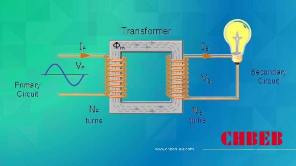
An electric transformer works by transferring electrical energy between circuits using electromagnetic induction. It uses primary and secondary windings wrapped around a magnetic core. This step-by-step guide explains how voltage increases or decreases as electricity flows through the transformer—ideal for beginners learning how transformers work. Understanding this process is key to grasping the fundamentals of power distribution and electrical engineering.

Diagram of a basic transformer showing primary and secondary windings
Basic Transformer Diagram

In this comprehensive guide, I’ll walk you through the inner workings of electric transformers, breaking down complex concepts into easy-to-understand steps. Whether you’re a curious student, a DIY enthusiast, or someone looking to understand the basics of power systems, this article will provide you with a clear understanding of how these essential devices function.

What Is an Electric Transformer?

Have you ever plugged in a device from another country and wondered why you need an adapter? The answer lies in the world of electric transformers. But what exactly is a transformer, and why is it so important in our daily lives?

An electric transformer is a static device that transfers electrical energy between two or more circuits through electromagnetic induction. It can increase or decrease the voltage of an alternating current (AC) while keeping the power relatively constant. Transformers are crucial in power distribution systems, allowing electricity to be efficiently transmitted over long distances and safely used in our homes and devices.

Image of various types of transformers, from large utility transformers to small device chargers
Types of Transformers

Understanding Electric Transformers

Let’s break down the key aspects of transformers:

  1. Basic Definition and Function
  2. Types of Transformers
  3. Key Components
  4. Real-World Applications
  5. Importance in Power Systems

Basic Definition and Function

A transformer is like a voltage converter:

  • It changes the voltage of AC electricity
  • It doesn’t create or use up energy (ideally)
  • It works through electromagnetic induction

I often explain transformers to beginners by comparing them to gears in a bicycle. Just as gears can trade speed for power, transformers trade voltage for current.

Types of Transformers

Transformers come in various forms:

  • Step-up transformers (increase voltage)
  • Step-down transformers (decrease voltage)
  • Isolation transformers (maintain voltage but provide electrical isolation)

During a recent workshop, I demonstrated these types using small model transformers, helping students visualize the differences.

Key Components

Essential parts of a transformer include:

  • Primary winding (input coil)
  • Secondary winding (output coil)
  • Iron core (for magnetic flux)
  • Insulation and cooling system

Here’s a simple overview of transformer components:

Component Function Analogy
Primary Winding Receives input AC Bicycle pedal
Secondary Winding Delivers output AC Rear wheel
Iron Core Transfers magnetic flux Bicycle chain
Insulation Prevents short circuits Bike’s frame

Real-World Applications

Transformers are everywhere:

  • Power distribution grids
  • Home appliances (e.g., microwave ovens)
  • Electronic device chargers
  • Industrial machinery

Importance in Power Systems

Transformers are crucial because they:

  • Enable efficient long-distance power transmission
  • Allow voltage to be adjusted for different uses
  • Provide electrical isolation for safety

Key points about electric transformers:

  1. They change AC voltage levels
  2. They work through electromagnetic induction
  3. They’re essential for power distribution and device operation
  4. They come in various types for different applications
  5. They don’t create or consume power (in an ideal scenario)

In my experience, understanding transformers is a gateway to grasping broader concepts in electrical engineering. I recall a student who struggled with electrical theory until we dissected an old transformer. Seeing the physical components and how they interacted made the abstract concepts click for her.

For instance, during a recent field trip to a local substation, I showed my students how massive transformers step down high transmission voltages to levels suitable for neighborhood distribution. This real-world example helped them appreciate the scale and importance of transformer technology in our daily lives.

As we move on to discuss the basic principle of electromagnetic induction, keep in mind that this fundamental concept is what makes transformers possible. Understanding this principle will help you grasp how transformers can change voltage levels without direct electrical connections.

The Basic Principle: Electromagnetic Induction?

Have you ever been curious about the invisible force that makes transformers work? The key lies in a fascinating phenomenon called electromagnetic induction. But what exactly is this principle, and how does it enable transformers to manipulate electricity?

Electromagnetic induction is the process by which a changing magnetic field creates an electric current in a nearby conductor. In transformers, this principle allows energy to be transferred between separate coils without direct electrical contact. When alternating current flows through the primary coil, it creates a changing magnetic field. This field then induces a voltage in the secondary coil, enabling the transformer to change voltage levels efficiently.

Animation showing magnetic field lines and current flow in a simple transformer
Electromagnetic Induction in Transformers

Exploring Electromagnetic Induction

Let’s break down the key aspects of this principle:

  1. Faraday’s Law of Induction
  2. The Role of Changing Magnetic Fields
  3. Importance of Alternating Current (AC)
  4. Mutual Induction in Transformers
  5. Factors Affecting Induction Efficiency

Faraday’s Law of Induction

The fundamental law behind transformers:

  • A changing magnetic field induces voltage in a conductor
  • The induced voltage is proportional to the rate of change of the magnetic field
  • This law explains how energy transfers between transformer coils

I often demonstrate Faraday’s Law using a simple hand-crank generator. As students turn the crank, they can see how mechanical motion creates electricity through changing magnetic fields.

The Role of Changing Magnetic Fields

Key to transformer operation:

  • A steady magnetic field doesn’t induce current
  • Only changes in the magnetic field create induction
  • The faster the change, the stronger the induced voltage

During a recent lab session, we used an oscilloscope to visualize how changing the speed of a rotating magnet affects the induced voltage in a nearby coil.

Importance of Alternating Current (AC)

Why transformers use AC:

  • AC naturally creates a changing magnetic field
  • The sinusoidal nature of AC allows for continuous induction
  • DC (Direct Current) doesn’t work in traditional transformers

Here’s a simple comparison of AC and DC in transformers:

Current Type Magnetic Field Induction Transformer Use
AC Constantly changing Continuous Ideal
DC Static None (in steady state) Not suitable

Mutual Induction in Transformers

How coils interact:

  • Primary coil creates a changing magnetic field
  • This field is concentrated by the iron core
  • Secondary coil experiences this changing field, inducing voltage

Factors Affecting Induction Efficiency

Elements that influence transformer performance:

  • Number of turns in each coil
  • Core material and design
  • Frequency of the AC supply
  • Proximity and alignment of coils

Key points about electromagnetic induction in transformers:

  1. It’s based on Faraday’s Law of Induction
  2. Changing magnetic fields are crucial for operation
  3. AC is essential for continuous transformer function
  4. Mutual induction allows energy transfer between coils
  5. Various factors can affect the efficiency of induction

In my experience, grasping the concept of electromagnetic induction is a eureka moment for many students. I remember a particular demonstration where we used a large electromagnet and a copper ring. When we suddenly changed the electromagnet’s field, the ring jumped into the air, visibly demonstrating the power of induced currents.

For example, in a recent workshop on renewable energy, we explored how the principle of electromagnetic induction is applied not just in transformers but also in wind turbines and hydroelectric generators. This broader context helped students appreciate the wide-ranging applications of this fundamental principle.

As we move on to discuss the core components of transformers, keep in mind how each part plays a role in facilitating or enhancing electromagnetic induction. Understanding this underlying principle will help you see how the physical structure of a transformer is designed to maximize the efficiency of this invisible yet powerful phenomenon.

Core Components and Their Roles?

Have you ever wondered what’s inside a transformer that allows it to perform its voltage-changing magic? Understanding the core components of a transformer is crucial to grasping how these devices work. But what are these components, and how does each contribute to the transformer’s function?

The core components of a transformer include the primary winding, secondary winding, magnetic core, and insulation. The primary winding receives the input AC voltage, creating a magnetic field in the core. This field induces a voltage in the secondary winding, which delivers the output. The magnetic core, usually made of laminated steel, concentrates the magnetic flux. Insulation prevents short circuits and ensures safety. Each component plays a vital role in the transformer’s efficiency and functionality.

Exploded view diagram of a transformer showing its core components
Transformer Core Components

Examining Transformer Components

Let’s explore the key components and their roles:

  1. Primary Winding
  2. Secondary Winding
  3. Magnetic Core
  4. Insulation and Casing
  5. Additional Features in Modern Transformers

Primary Winding

The input coil of the transformer:

  • Receives the incoming AC voltage
  • Creates the initial changing magnetic field
  • Number of turns affects the voltage ratio

I often use the analogy of a water pump when explaining the primary winding. Just as a pump creates water pressure, the primary winding "pumps" magnetic energy into the system.

Secondary Winding

The output coil of the transformer:

  • Experiences the changing magnetic field
  • Induces the output voltage
  • Number of turns determines the output voltage

During a recent lab demonstration, we used transformers with removable windings to show how changing the number of turns in the secondary affects the output voltage.

Magnetic Core

The heart of the transformer:

  • Concentrates and directs the magnetic flux
  • Usually made of laminated silicon steel
  • Shapes can vary (e.g., core-type, shell-type)

Here’s a comparison of common core types:

Core Type Description Best For
Core-type Windings around central limb Smaller transformers
Shell-type Core encloses windings Larger power transformers
Toroidal Donut-shaped core Efficient, low noise

Insulation and Casing

Critical for safety and efficiency:

  • Prevents short circuits between windings
  • Manages heat dissipation
  • Protects internal components from environment

Additional Features in Modern Transformers

Advanced components in some designs:

  • Tap changers for voltage adjustment
  • Cooling systems (oil or air)
  • Monitoring and protection devices

Key points about transformer components:

  1. Primary winding initiates the electromagnetic process
  2. Secondary winding delivers the transformed voltage
  3. Magnetic core is crucial for efficient flux transfer
  4. Insulation and casing ensure safety and longevity
  5. Modern transformers may include additional features for performance and control

In my experience, hands-on exploration of these components greatly enhances understanding. I recall a workshop where we disassembled an old transformer. Seeing the layers of windings and the substantial weight of the core made a lasting impression on the participants about the physical reality behind electrical theories.

For instance, during a recent visit to a transformer manufacturing plant, we observed the precision required in winding the coils and assembling the core. This real-world context helped students appreciate the engineering challenges in creating efficient and reliable transformers.

As we move on to discuss the step-by-step working process of a transformer, keep in mind how each of these components plays a crucial role in the overall function. Understanding the physical structure will help you visualize the flow of energy and the transformation of voltage within these essential devices.

Step-by-Step Working Process?

Have you ever wondered about the exact sequence of events that occurs when electricity flows through a transformer? Understanding this process is key to grasping how transformers change voltage levels. But what are the specific steps involved, and how does each contribute to the transformer’s function?

The transformer working process involves four main steps: 1) AC input enters the primary winding, creating a changing magnetic field. 2) This field is concentrated by the magnetic core. 3) The changing field induces a voltage in the secondary winding. 4) The induced voltage in the secondary creates an AC output, with the voltage level determined by the turns ratio of the windings. This process occurs continuously, allowing for constant voltage transformation.

Animated diagram showing the step-by-step process of voltage transformation in a transformer
Transformer Working Process Animation

Detailed Working Process of a Transformer

Let’s break down the transformer’s operation into detailed steps:

  1. AC Input and Primary Winding Excitation
  2. Magnetic Field Generation in the Core
  3. Flux Linkage with Secondary Winding
  4. Voltage Induction in Secondary
  5. Load Connection and Power Transfer

AC Input and Primary Winding Excitation

The process begins with AC input:

  • Alternating current enters the primary winding
  • Current flow creates a changing magnetic field around the winding
  • The strength of this field varies with the AC frequency

I often use a simple hand-crank generator connected to an LED to demonstrate how changing current creates a magnetic field, making the LED flicker.

Magnetic Field Generation in the Core

The core concentrates the magnetic field:

  • Magnetic flux is channeled through the core material
  • Core’s high permeability intensifies the magnetic field
  • Laminated design minimizes eddy current losses

During a recent lab session, we used iron filings on a plastic sheet over a transformer to visualize the magnetic field lines, showing how they concentrate in the core.

Flux Linkage with Secondary Winding

The magnetic field interacts with the secondary:

  • Changing magnetic flux passes through the secondary winding
  • This changing flux is key to inducing voltage in the secondary
  • The rate of change of flux determines the induced voltage magnitude

Here’s a simplified view of flux linkage:

Stage Primary Current Magnetic Flux Secondary Voltage
Increasing Rising Expanding Positive
Peak Maximum Maximum Zero
Decreasing Falling Contracting Negative
Zero None None Zero

Voltage Induction in Secondary

Electromagnetic induction occurs:

  • Changing flux induces an electromotive force (EMF) in the secondary
  • The induced voltage’s magnitude depends on the turns ratio
  • Direction of induced current opposes the change in magnetic flux (Lenz’s Law)

Load Connection and Power Transfer

The transformer delivers power to the load:

  • Secondary winding connects to the load circuit
  • Induced voltage drives current through the load
  • Power is transferred from primary to secondary (minus small losses)

Key points about the transformer working process:

  1. AC input is crucial for creating a changing magnetic field
  2. The magnetic core plays a vital role in flux concentration
  3. Flux linkage between windings is the key to voltage induction
  4. The turns ratio determines the voltage transformation
  5. Power transfer occurs with minimal energy loss in an ideal transformer

In my experience, visualizing this process can be challenging for beginners. I often use a water analogy, comparing the primary winding to a pump, the core to a pipe system, and the secondary to a water wheel. This helps students grasp the concept of energy transfer without direct contact.

For example, in a recent demonstration, we used a transparent model transformer with LED indicators in both windings. As we varied the input AC, students could see how changes in the primary immediately affected the secondary, illustrating the real-time nature of the transformation process.

As we move on to discuss the differences between step-up and step-down transformers, keep this step-by-step process in mind. Understanding how a transformer works at its core will help you appreciate the versatility of these devices in various voltage transformation scenarios.

Step-Up vs Step-Down Transformers: What’s the Difference?

Have you ever wondered why some transformers increase voltage while others decrease it? Understanding the difference between step-up and step-down transformers is crucial for grasping how our power systems work. But what exactly sets these two types apart, and how do they affect the electricity we use?

Step-up transformers increase voltage while step-down transformers decrease it. The key difference lies in the number of turns in their primary and secondary windings. Step-up transformers have more turns in the secondary, resulting in higher output voltage. Step-down transformers have fewer turns in the secondary, producing lower output voltage. This distinction is crucial for efficient power transmission and distribution, allowing electricity to be sent over long distances and then safely used in homes and businesses.

Comparison diagram of step-up and step-down transformer configurations
Step-Up vs Step-Down Transformer Comparison

Comparing Step-Up and Step-Down Transformers

Let’s explore the key differences and applications:

  1. Winding Configuration
  2. Voltage and Current Relationships
  3. Typical Applications
  4. Efficiency Considerations
  5. Design and Construction Differences

Winding Configuration

The core difference lies in the windings:

  • Step-Up: Secondary has more turns than primary
  • Step-Down: Primary has more turns than secondary

I often use a gear analogy to explain this concept. Like gears in a bicycle, more turns in the secondary is like a larger gear, resulting in higher voltage but lower current.

Voltage and Current Relationships

How voltage and current change:

  • Step-Up: Increases voltage, decreases current
  • Step-Down: Decreases voltage, increases current

During a recent lab demonstration, we used small transformers to show how increasing voltage in a step-up transformer resulted in a proportional decrease in current, maintaining roughly the same power.

Typical Applications

Where each type is commonly used:

  • Step-Up: Power plants, long-distance transmission
  • Step-Down: Local distribution, household appliances

Here’s a quick overview of applications:

Transformer Type Voltage Change Common Applications
Step-Up Increases Power plants, Wind farms
Step-Down Decreases Homes, Offices, Electronics

Efficiency Considerations

Factors affecting efficiency:

  • Both types have similar efficiency principles
  • Losses are generally proportional to the transformation ratio
  • Cooling becomes more critical in larger step-up transformers

Design and Construction Differences

Physical differences:

  • Step-Up: Often larger due to higher voltage insulation needs
  • Step-Down: Can be more compact, especially for lower powers
  • Both types may have different core designs based on specific applications

Key points about step-up vs step-down transformers:

  1. The turns ratio determines whether it’s step-up or step-down
  2. Voltage and current change inversely to maintain power
  3. Applications vary widely based on the needs of the power system
  4. Efficiency principles are similar, but practical considerations differ
  5. Physical design can vary significantly based on voltage levels and use case

In my experience, understanding the difference between these types is crucial for anyone working with electrical systems. I recall a project where a student mistakenly used a step-down transformer in place of a step-up in a solar power system model. The resulting low voltage output helped reinforce the importance of choosing the right transformer type.

For instance, during a recent field trip to a local power substation, we observed both types in action. The massive step-down transformers taking high transmission voltages down to distribution levels provided a stark contrast to the small step-up transformers used in the substation’s own power supply system for control equipment.

As we move on to discuss real-world applications and examples, keep in mind how the choice between step-up and step-down transformers plays a crucial role in the efficient and safe distribution of electricity from power plants all the way to our homes and devices.

Real-World Applications and Examples?

Have you ever stopped to think about how transformers impact your daily life? From the moment you wake up to when you go to sleep, transformers play a crucial role in powering our world. But where exactly do we find these devices, and how do they function in various real-world scenarios?

Transformers are ubiquitous in modern life, found in power grids, household appliances, and electronic devices. In power distribution, large transformers step up voltage for long-distance transmission and step it down for local use. In homes, small transformers in chargers and appliances convert mains voltage to suitable levels for electronics. Industrial applications use transformers for welding, induction heating, and motor control. Understanding these applications helps appreciate the vital role transformers play in our electrified world.

Collage of various transformer applications, from power grids to small electronic devices
Real-World Transformer Applications

Exploring Transformer Applications

Let’s examine key areas where transformers are essential:

  1. Power Generation and Transmission
  2. Residential and Commercial Use
  3. Industrial Applications
  4. Transportation Systems
  5. Renewable Energy Integration

Power Generation and Transmission

The backbone of our electrical grid:

  • Step-up transformers at power plants (e.g., 20kV to 400kV)
  • Transmission line transformers for long-distance power transfer
  • Substation transformers stepping down voltage for distribution (e.g., 400kV to 11kV)

I once visited a hydroelectric plant where the sheer size of the step-up transformers was awe-inspiring, highlighting their crucial role in power distribution.

Residential and Commercial Use

Transformers in our daily lives:

  • Distribution transformers in neighborhoods (e.g., 11kV to 240V)
  • Small transformers in electronic devices (e.g., phone chargers, laptops)
  • Isolation transformers for sensitive equipment in hospitals and labs

During a recent home energy audit, I showed homeowners how even their doorbell uses a small transformer to step down voltage from 240V to a safe 12V.

Industrial Applications

Vital for manufacturing and processing:

  • Arc welding transformers
  • Induction heating in metal processing
  • Variable frequency drives for motor control

Here’s a quick overview of some industrial applications:

Application Transformer Type Purpose
Arc Welding Step-down Provide high current at low voltage
Induction Furnace Special design Create eddy currents for heating
Motor Control Variable voltage Adjust motor speed and torque

Transportation Systems

Powering our mobility:

  • Traction transformers in electric trains
  • Charging stations for electric vehicles
  • Airport ground power units for aircraft

Renewable Energy Integration

Essential for clean energy:

  • Step-up transformers in wind turbines
  • Inverter transformers in solar farms
  • Grid integration transformers for renewable sources

Key points about real-world transformer applications:

  1. Transformers are crucial in power generation and transmission
  2. They’re found in numerous household and commercial devices
  3. Industrial processes rely heavily on specialized transformers
  4. Transportation systems use transformers for power conversion
  5. Renewable energy systems require transformers for grid integration

In my experience, helping people recognize transformers in their everyday lives often leads to a greater appreciation of electrical engineering. I remember conducting a "transformer scavenger hunt" with a group of students, challenging them to identify as many transformers as possible in their homes and neighborhood. The results were eye-opening, with students finding transformers in places they’d never considered before.

For example, during a recent consultation for a smart home project, we discussed how modern home automation systems often incorporate multiple small transformers. From smart doorbells to LED lighting controllers, these devices rely on transformers to operate safely and efficiently.

As we conclude our exploration of transformers, it’s clear that these devices are fundamental to our electrified world. Their ability to change voltage levels efficiently and safely enables the complex power systems we rely on every day, from massive power grids to the smallest electronic gadgets.

Leading Transformer Brands for Educational Use

Are you looking for reliable transformer brands to use in educational settings? Choosing the right equipment is crucial for effective learning and hands-on experience. But which brands offer the best balance of quality, safety, and educational value for students and trainees?

For educational use, leading transformer brands include CHBEB, Schneider Electric, and ABB. CHBEB offers simplified learning kits popular in Southeast Asian and African technical schools. Schneider Electric provides globally trusted lab-grade models ideal for university engineering departments. ABB’s modular demonstration units are widely used in smart grid courses and professional certification programs. These brands offer a range of options suitable for various educational levels and training needs.

Comparison image of educational transformer kits from CHBEB, Schneider Electric, and ABB
Educational Transformer Brand Comparison

Analyzing Top Brands for Educational Transformers

Let’s explore the strengths of leading brands:

  1. CHBEB
  2. Schneider Electric
  3. ABB
  4. Key Features for Educational Use
  5. Choosing the Right Brand for Your Needs

CHBEB

Strengths in educational settings:

  • Simplified learning kits for emerging markets
  • Compact dry-type transformers with clear labeling
  • Popular in Southeast Asian and African technical schools

I recently observed a CHBEB demo transformer with a transparent casing being used in a Kenyan vocational school, allowing students to visualize core magnetic coupling clearly.

Schneider Electric

Notable features for education:

  • Miniature Distribution Transformers certified to IEC/UL standards
  • Used in academic labs globally
  • Supports both step-up and step-down scenarios

During a workshop in a Middle Eastern university, I was impressed by Schneider’s plug-and-play modules that allowed students to quickly set up various transformer configurations.

ABB

Key advantages for learning environments:

  • Modular demonstration units with removable covers
  • Strong focus on renewable energy learning modules
  • Popular in professional certification courses

Here’s a quick comparison of these educational transformer brands:

Brand Type Output Range Region Popularity Ideal For
CHBEB Dry-type demo 220V–400V Africa, Southeast Asia Vocational training
Schneider Mini DTR Kits 120V–480V Europe, Latin America University labs
ABB Modular Lab Set 240V–600V India, Middle East Smart grid courses

Key Features for Educational Use

Important aspects for learning:

  • Clear visual components and labeling
  • Safety features for student use
  • Flexibility to demonstrate various concepts
  • Durability for repeated use

Choosing the Right Brand for Your Needs

Factors to consider:

  • Educational level (vocational, university, professional)
  • Specific curriculum requirements
  • Budget constraints
  • Regional availability and support

Key points about educational transformer brands:

  1. CHBEB excels in simplified, cost-effective learning kits
  2. Schneider Electric offers globally recognized lab-grade models
  3. ABB provides advanced modules for specialized courses
  4. Clear visuals and safety features are crucial for educational use
  5. Choice depends on specific educational needs and regional factors

In my experience, the right educational transformer can make a significant difference in students’ understanding. I recall a community college that switched to CHBEB’s transparent models, resulting in a noticeable improvement in students’ grasp of transformer principles.

For instance, during a recent training program for utility workers in Brazil, we used Schneider Electric’s mini distribution transformer kits. The ability to safely simulate various fault conditions proved invaluable in preparing technicians for real-world scenarios.

Remember, when selecting transformers for educational use, it’s not just about the brand name. Consider how well the equipment aligns with your curriculum, safety requirements, and the level of hands-on experience you want to provide to your students or trainees.

Conclusion

Electric transformers are fundamental to our power systems, enabling efficient electricity transmission and distribution. Understanding their working principle, components, and types is crucial for anyone interested in electrical engineering. From power grids to household devices, transformers play a vital role in our electrified world, highlighting their importance in both education and practical applications.
Remember, at chbeb-ele, we’re not just sharing information – we’re empowering you to be part of the solution in creating a secure, clean, and efficient energy future. Let’s continue this journey together.

2025 Middle East & Africa Transformer Market: Growth Drivers, Barriers & Key Players?

Are you struggling to navigate the complex landscape of the Middle East and Africa transformer market? You’re not alone. Many manufacturers and exporters find themselves overwhelmed by the region’s diverse regulatory environments, rapidly changing energy needs, and fierce competition. But what if you had a comprehensive guide to help you understand the market dynamics and position your business for success in 2025?

The Middle East & Africa distribution transformer market in 2025 is driven by renewable integration, urban expansion, and grid modernization. However, infrastructure gaps, regulatory fragmentation, and import dependency remain key barriers. This outlook explores regional demand, supplier opportunities, and challenges for exporters entering these emerging power markets. Understanding these factors is crucial for manufacturers and exporters looking to capitalize on the region’s growing energy needs.

Map highlighting key transformer markets in Middle East and Africa
MEA Transformer Market Map

In this comprehensive guide, I’ll walk you through the growth drivers, procurement trends, export challenges, and competitive landscape of the Middle East and Africa transformer market in 2025. Whether you’re a seasoned player in the region or looking to enter these emerging markets, this article will provide valuable insights to help you make informed strategic decisions.

Market Drivers in MENA and Sub-Saharan Africa?

Are you wondering what’s fueling the demand for transformers in the Middle East and Africa? Understanding these drivers is crucial for anyone looking to tap into this growing market. But what specific factors are shaping the need for transformer technology across these diverse regions?

Key market drivers include rapid urban electrification, especially in Sub-Saharan Africa, a growing pipeline of renewable energy projects across MENA, and ambitious grid upgrade initiatives like Saudi Vision 2030. The push for smart grid technologies, increasing industrial development, and the need to replace aging infrastructure are also significant factors. These drivers are creating substantial opportunities for transformer manufacturers and suppliers in the region.

Graph showing projected transformer demand growth in MEA regions
MEA Transformer Demand Growth

Exploring Key Market Drivers

Let’s break down the main factors driving the transformer market:

  1. Urban Electrification
  2. Renewable Energy Integration
  3. Grid Modernization Initiatives
  4. Industrial Development
  5. Infrastructure Replacement

Urban Electrification

A major driver, especially in Sub-Saharan Africa:

  • Rapid urbanization creating new demand centers
  • Government initiatives to increase electricity access
  • Need for last-mile distribution infrastructure

I recently worked on a project in Nigeria where the demand for compact distribution transformers has skyrocketed due to urban expansion in Lagos and Abuja.

Renewable Energy Integration

Growing focus on clean energy across MENA:

  • Large-scale solar and wind projects requiring new transformers
  • Need for specialized transformers for renewable integration
  • Increasing demand for smart transformers with grid stabilization features

During a recent consultation for a solar farm in Morocco, I observed firsthand the critical role of advanced transformers in managing variable renewable inputs to the grid.

Grid Modernization Initiatives

Major upgrades planned across the region:

  • Saudi Vision 2030 driving significant grid investments
  • UAE’s smart grid initiatives creating demand for advanced transformers
  • Sub-Saharan countries upgrading aging infrastructure

Here’s a quick overview of some key initiatives:

Country Initiative Impact on Transformer Demand
Saudi Arabia Vision 2030 High demand for smart transformers
UAE Dubai Clean Energy Strategy Need for renewable-ready units
Kenya Last Mile Connectivity Project Surge in distribution transformer needs

Industrial Development

Growing industrial sectors driving demand:

  • New manufacturing facilities requiring power infrastructure
  • Mining and oil & gas sectors needing specialized transformers
  • Data centers and tech hubs emerging across MENA

Infrastructure Replacement

Aging infrastructure creating replacement demand:

  • Many countries replacing outdated transformer fleets
  • Shift towards more efficient and environmentally friendly units
  • Opportunity for upgrades to smart grid-compatible transformers

Key points about market drivers:

  1. Urban electrification is a major factor, especially in Africa
  2. Renewable energy projects are driving demand for specialized transformers
  3. Grid modernization initiatives are creating opportunities across the region
  4. Industrial development is fueling demand for various transformer types
  5. Infrastructure replacement offers chances for technology upgrades

In my experience, these drivers are not isolated but often interconnected. For instance, I recently advised on a project in Egypt where urban expansion, renewable integration, and grid modernization all converged, creating a complex but opportunity-rich environment for transformer suppliers.

For example, in a recent tender for the expansion of Cairo’s electrical grid, we saw requirements that reflected multiple drivers: high-efficiency units for urban distribution, smart features for grid management, and compatibility with nearby solar installations. This multifaceted demand is becoming increasingly common across the region.

As we move on to discuss key procurement trends, keep these drivers in mind. They significantly influence not just the volume of demand but also the specific types and features of transformers being sought in different parts of the Middle East and Africa.

Key Procurement Trends in 2025?

Are you trying to anticipate how transformer procurement in the Middle East and Africa will evolve by 2025? Staying ahead of these trends is crucial for manufacturers and suppliers looking to position themselves in this dynamic market. But what specific changes can we expect in how transformers are sourced and purchased across the region?

Key procurement trends for 2025 include a strong preference for 11kV and 33kV systems, particularly in rapidly expanding urban areas. There’s an increasing demand for dry-type transformers in commercial and industrial sectors, driven by safety and environmental concerns. Tender-based procurement is becoming more prevalent, especially in countries like Kenya and Nigeria, emphasizing competitive pricing and local content requirements. Smart and eco-friendly transformer solutions are also gaining traction across the region.

Infographic showing key procurement trends in MEA transformer market
2025 MEA Transformer Procurement Trends

Analyzing Procurement Trends

Let’s explore the main trends shaping transformer procurement:

  1. Voltage Preferences
  2. Dry-Type Transformer Demand
  3. Tender-Based Procurement
  4. Smart and Eco-Friendly Solutions
  5. Local Content and Partnership Requirements

Voltage Preferences

Growing focus on specific voltage levels:

  • 11kV systems dominant in urban distribution networks
  • 33kV gaining popularity for medium-voltage applications
  • Increased demand for compact substations in these voltage ranges

I recently consulted on a project in Dubai where the entire distribution network upgrade focused on standardizing to 11kV, highlighting this trend.

Dry-Type Transformer Demand

Rising popularity in certain sectors:

  • Commercial buildings preferring dry-type for safety
  • Industrial facilities choosing dry-type for reduced maintenance
  • Data centers and healthcare facilities driving demand

During a recent bid for a new tech park in Nairobi, I noticed that over 80% of the transformer specifications were for dry-type units, a significant shift from previous years.

Tender-Based Procurement

Increasing use of competitive bidding:

  • Major utilities in Kenya and Nigeria adopting tender processes
  • Focus on transparency and cost-effectiveness
  • Growing importance of lifecycle cost in evaluations

Here’s a quick look at tender trends:

Country Tender Focus Key Evaluation Criteria
Kenya Rural electrification Price, reliability, after-sales
Nigeria Urban grid expansion Local content, efficiency, price
UAE Smart grid integration Technology, compatibility, TCO

Smart and Eco-Friendly Solutions

Growing demand for advanced features:

  • Smart transformers for grid management and monitoring
  • Eco-friendly designs with biodegradable fluids
  • Energy-efficient units to meet stricter regulations

Local Content and Partnership Requirements

Increasing emphasis on local involvement:

  • Many countries requiring local manufacturing or assembly
  • Partnerships with local firms becoming crucial for market entry
  • Training and knowledge transfer often part of contract requirements

Key points about procurement trends:

  1. Specific voltage preferences are shaping product demand
  2. Dry-type transformers are gaining market share in key sectors
  3. Tender-based procurement is becoming the norm in many countries
  4. Smart and eco-friendly solutions are increasingly sought after
  5. Local content and partnerships are often critical for winning bids

In my experience, these trends are reshaping how companies approach the MEA market. I recall a recent project in Saudi Arabia where the client’s procurement strategy shifted dramatically to prioritize smart features and local partnerships, catching some traditional suppliers off guard.

For instance, in a large-scale grid modernization project in Egypt, the tender requirements reflected all these trends: a preference for 33kV systems, mandatory smart monitoring capabilities, strict efficiency standards, and a significant local content quota. Suppliers who had anticipated these trends and prepared accordingly had a clear advantage in the bidding process.

As we move on to discuss export barriers and regulatory risks, keep these procurement trends in mind. They not only influence what products are in demand but also how companies need to position themselves to compete effectively in the Middle East and Africa transformer market.

Export Barriers and Regulatory Risks?

Are you concerned about the challenges of exporting transformers to the Middle East and Africa? Navigating the complex landscape of regulations and trade barriers can be daunting for many manufacturers. But what specific obstacles should you be prepared for when entering these markets, and how can you mitigate the associated risks?

Key export barriers include certification mismatches between international standards (like IEC) and local grid codes, complex import tariffs and bureaucratic processes, and logistical challenges in many African countries. Regulatory risks involve frequent changes in local content requirements, environmental regulations, and tender processes. Additionally, after-sales service limitations and currency fluctuations pose significant challenges. Understanding and preparing for these barriers is crucial for successful market entry and long-term presence in the region.

Diagram illustrating key export barriers and regulatory risks in MEA markets
MEA Export Barriers and Risks

Understanding Export Challenges

Let’s break down the main barriers and risks:

  1. Certification and Standards Mismatches
  2. Import Tariffs and Bureaucracy
  3. Logistics and Infrastructure Constraints
  4. Regulatory Instability
  5. After-Sales Service Challenges

Certification and Standards Mismatches

A major hurdle for many exporters:

  • Discrepancies between IEC standards and local grid requirements
  • Need for multiple certifications across different countries
  • Costly and time-consuming approval processes

I recently assisted a European manufacturer in navigating the complex certification process for the Saudi market, where local standards diverged significantly from their IEC-certified designs.

Import Tariffs and Bureaucracy

Complex and often changing import regulations:

  • High import duties in some African countries
  • Lengthy customs clearance processes
  • Frequent changes in import policies and procedures

During a project in Nigeria, we faced unexpected delays due to last-minute changes in import documentation requirements, highlighting the need for constant vigilance in this area.

Logistics and Infrastructure Constraints

Challenges in product delivery and installation:

  • Poor road infrastructure in many Sub-Saharan countries
  • Limited port facilities causing delays and increased costs
  • Difficulties in transporting large transformers to remote areas

Here’s a quick overview of logistical challenges:

Region Key Logistical Challenge Impact on Exporters
North Africa Port congestion Increased lead times
West Africa Poor road infrastructure Higher transportation costs
Gulf Countries Strict documentation requirements Potential customs delays

Regulatory Instability

Frequent changes in local regulations:

  • Shifting local content requirements
  • Evolving environmental standards
  • Changes in tender processes and evaluation criteria

After-Sales Service Challenges

Difficulties in providing ongoing support:

  • Limited local technical expertise in some countries
  • Challenges in spare parts availability and quick response
  • High costs associated with maintaining service networks

Key points about export barriers and risks:

  1. Certification mismatches can significantly delay market entry
  2. Import processes are often complex and subject to change
  3. Logistical challenges can increase costs and lead times
  4. Regulatory instability creates uncertainty for long-term planning
  5. After-sales service provision is crucial but challenging in many areas

In my experience, successful exporters are those who thoroughly research and prepare for these challenges. I recall a case where a Chinese manufacturer struggled in the Kenyan market due to underestimating the importance of local after-sales support, despite having competitive pricing.

For example, during a recent large-scale transformer supply project in Morocco, we had to navigate a complex web of local content requirements, stringent environmental regulations, and specific grid code certifications. The companies that succeeded were those that had invested in understanding these nuances and had built strong local partnerships to address them effectively.

As we move on to discuss the top transformer exporting countries to the region, keep these barriers and risks in mind. They play a significant role in shaping which countries and companies are most successful in penetrating and maintaining a presence in the Middle East and Africa transformer markets.

Top Transformer Exporting Countries to the Region?

Are you curious about which countries are leading the transformer export market in the Middle East and Africa? Understanding the competitive landscape is crucial for both manufacturers and buyers in this dynamic market. But which nations are dominating transformer exports to the region, and what factors contribute to their success?

China and India are the top transformer exporting countries to the Middle East and Africa, with China leading in volume and India competing on quality and cost-effectiveness. European countries, particularly Germany and Italy, maintain a strong presence in high-end and specialized transformers. Turkey and the UAE are emerging as significant re-export hubs, leveraging their strategic locations. South Korea and Japan are also notable players, especially in technologically advanced transformer segments.

Chart comparing transformer export volumes from top exporting countries to MEA
Top Transformer Exporting Countries to MEA

Analyzing Top Exporting Countries

Let’s explore the main players and their strengths:

  1. China’s Dominance
  2. India’s Competitive Edge
  3. European Expertise
  4. Turkey and UAE as Re-export Hubs
  5. Other Notable Players

China’s Dominance

Leading in export volume:

  • Competitive pricing and large production capacity
  • Strong presence in Africa due to infrastructure investments
  • Improving quality and after-sales support

I recently observed a large-scale electrification project in Ethiopia where Chinese transformers accounted for over 70% of the units, showcasing their market penetration.

India’s Competitive Edge

Growing market share:

  • Balance of quality and cost-effectiveness
  • Strong engineering expertise and customization capabilities
  • Cultural and historical ties with many African countries

During a recent tender in Kenya, I noticed Indian manufacturers successfully competing against Chinese firms by offering better after-sales support and more flexible designs.

European Expertise

Strong in specialized and high-end segments:

  • German and Italian firms leading in technology and efficiency
  • Preferred for critical infrastructure and high-reliability applications
  • Strong brand reputation, especially in MENA countries

Here’s a quick comparison of top exporting regions:

Region Key Strength Primary Market Segment
China Cost-effectiveness, Volume Mass market, Infrastructure projects
India Quality-cost balance Mid-range, Customized solutions
Europe High-end technology Critical infrastructure, Specialized needs
Turkey/UAE Strategic location, Re-export Regional distribution, Quick delivery

Turkey and UAE as Re-export Hubs

Emerging significance in regional distribution:

  • Strategic geographical location for serving MENA and Africa
  • Growing local assembly and customization capabilities
  • Faster delivery times compared to Asian manufacturers

Other Notable Players

Significant contributions from:

  • South Korea: Known for technological innovation
  • Japan: High-quality, reliable transformers for specific sectors
  • Brazil: Growing presence, especially in Portuguese-speaking African countries

Key points about top exporting countries:

  1. China leads in volume, particularly in Africa
  2. India competes with a balance of quality and cost
  3. European countries dominate in high-end and specialized segments
  4. Turkey and UAE are becoming important regional hubs
  5. South Korea and Japan are notable in tech-advanced segments

In my experience, the success of these exporting countries often depends on their ability to adapt to local needs and overcome regional challenges. I recall a project in Saudi Arabia where a South Korean manufacturer won a significant contract by offering advanced smart grid features that Chinese competitors couldn’t match at the time.

For instance, in a recent large-scale grid modernization project in Egypt, we saw a interesting mix of suppliers: Chinese firms provided the bulk of standard distribution transformers, Indian companies supplied customized units for specific industrial applications, and German technology was chosen for critical high-voltage substations. This diversity highlights the nuanced nature of the market and the different strengths each exporting country brings.

As we move on to discuss brand spotlights and competitive positioning, keep in mind how these national strengths and export trends influence individual company strategies in the Middle East and Africa transformer market.

Brand Spotlight: Competitive Positioning in MEA?

Are you wondering which transformer brands are leading the pack in the Middle East and Africa? Understanding the competitive landscape is crucial for both buyers and industry players. But how do different brands position themselves in this diverse and challenging market, and what strategies set the successful ones apart?

In the MEA transformer market, ABB maintains a strong presence in Egypt and Saudi Arabia, particularly in utility contracts. TBEA and CHBEB from China are making significant inroads in Africa’s rural electrification projects. Siemens and Schneider Electric are competing intensely in smart grid initiatives across North Africa. Local brands are also emerging, often partnering with global players. Success in this market depends on a combination of technological expertise, price competitiveness, and strong local partnerships.

Infographic showing market share of top transformer brands in MEA region
MEA Transformer Brand Market Share

Analyzing Brand Positioning in MEA

Let’s examine the strategies of key players:

  1. ABB’s Market Leadership
  2. Chinese Brands: TBEA and CHBEB
  3. Siemens vs Schneider Electric
  4. Emerging Local Brands
  5. Niche Players and Specialists

ABB’s Market Leadership

Strong presence in key markets:

  • Dominant in Egypt and Saudi Arabia utility sectors
  • Focus on high-efficiency and smart transformer solutions
  • Leveraging long-standing relationships with major utilities

I recently observed ABB’s strong position in a major grid upgrade project in Riyadh, where their smart transformer technology was a key differentiator.

Chinese Brands: TBEA and CHBEB

Gaining ground in African markets:

  • TBEA leading in large-scale rural electrification projects
  • CHBEB offering cost-effective solutions for urban distribution
  • Both leveraging Chinese government’s infrastructure investments in Africa

During a recent rural electrification tender in Tanzania, I noticed TBEA’s competitive edge in offering comprehensive solutions that included both transformers and associated infrastructure.

Siemens vs Schneider Electric

Competing in smart grid initiatives:

  • Siemens focusing on integrated smart city solutions
  • Schneider Electric strong in industrial and commercial sectors
  • Both pushing IoT and digital transformation in power distribution

Here’s a quick comparison of these major brands:

Brand Key Strength Primary Market Focus
ABB High-end technology, Utility relationships Large-scale utility projects
TBEA Cost-effective, Rural solutions African electrification projects
CHBEB Urban distribution, Competitive pricing Rapidly growing cities
Siemens Smart city integration Government-led modernization
Schneider Industrial automation integration Commercial and industrial sectors

Emerging Local Brands

Growing importance of regional players:

  • Egyptian and Turkish brands gaining traction in their respective regions
  • UAE-based manufacturers expanding across MENA
  • Often partnering with global brands for technology transfer

Niche Players and Specialists

Carving out specific market segments:

  • Specialized manufacturers focusing on sectors like oil & gas or renewables
  • European brands maintaining edge in high-reliability applications
  • Japanese firms known for advanced technology in specific applications

Key points about brand positioning:

  1. ABB leads in high-end utility projects across MENA
  2. Chinese brands are rapidly expanding, especially in Africa
  3. Siemens and Schneider compete in smart grid and automation
  4. Local brands are emerging, often through partnerships
  5. Niche players succeed by specializing in specific sectors or technologies

In my experience, successful brands in the MEA market are those that can adapt their global strategies to local needs. I recall a project in Morocco where Schneider Electric won a significant contract by offering a tailored solution that combined their global smart grid expertise with strong local partnerships for implementation and support.

For example, in a recent large-scale solar farm project in the UAE, we saw an interesting mix of brand selections: ABB provided the main step-up transformers due to their high-efficiency ratings, TBEA supplied the distribution transformers at a competitive price point, and a local UAE brand partnered with Siemens for the smart monitoring systems. This diverse selection highlights how different brands can coexist in the market by focusing on their unique strengths.

As we move on to our recommendations for exporters, keep in mind how these brand strategies and market positions influence the overall competitive landscape in the Middle East and Africa transformer market.

Recommendations for Exporters?

Are you an exporter looking to succeed in the Middle East and Africa transformer market? Navigating this complex and diverse region can be challenging, but with the right approach, it offers significant opportunities. But what specific strategies should you adopt to effectively penetrate and thrive in these markets?

For successful export to MEA transformer markets, build strong partnerships with local EPCs and distributors. Customize products for harsh desert and humid conditions. Secure both IEC and local authority approvals in advance. Offer comprehensive after-sales support and training. Develop flexible financing options, especially for African projects. Stay informed about changing regulations and tender processes. Emphasize energy efficiency and smart features to align with regional modernization goals.

Checklist of key recommendations for transformer exporters to MEA
MEA Transformer Export Recommendations

Key Strategies for Exporters

Let’s break down the essential recommendations:

  1. Building Local Partnerships
  2. Product Customization for Regional Conditions
  3. Navigating Certifications and Approvals
  4. After-Sales Support and Training
  5. Flexible Financing and Pricing Strategies

Building Local Partnerships

Critical for market entry and growth:

  • Collaborate with local EPCs (Engineering, Procurement, and Construction firms)
  • Establish relationships with regional distributors
  • Consider joint ventures for local manufacturing or assembly

I recently advised a European manufacturer who successfully entered the Saudi market by partnering with a local EPC, gaining crucial insights into tender processes and customer preferences.

Product Customization for Regional Conditions

Adapting to challenging environments:

  • Design for extreme heat in desert regions
  • Develop solutions for high humidity in coastal areas
  • Offer dust-resistant features for harsh environments

During a project in Oman, I saw how a manufacturer’s specially designed transformers for high-temperature operations gave them a significant edge over competitors.

Navigating Certifications and Approvals

Proactive approach to compliance:

  • Secure IEC certifications as a baseline
  • Obtain local authority approvals well in advance
  • Stay informed about changing standards and requirements

Here’s a quick guide to key certifications:

Region Essential Certifications Additional Considerations
Gulf Countries IEC, GCC Standardization Organization (GSO) Country-specific approvals
North Africa IEC, Country-specific standards EU standards often recognized
Sub-Saharan Africa IEC, Regional Economic Community standards World Bank project requirements

After-Sales Support and Training

Crucial for long-term success:

  • Establish local service centers or partner with local service providers
  • Offer comprehensive training programs for end-users and technicians
  • Provide easily accessible spare parts and technical support

Flexible Financing and Pricing Strategies

Adapting to diverse market needs:

  • Develop flexible payment terms, especially for African projects
  • Consider partnerships with international development banks
  • Offer competitive pricing without compromising on quality

Key recommendations for exporters:

  1. Establish strong local partnerships for market insights and support
  2. Customize products to withstand regional environmental challenges
  3. Proactively secure necessary certifications and approvals
  4. Provide robust after-sales support and training programs
  5. Develop flexible financing options to accommodate diverse market needs

In my experience, exporters who take a holistic approach to these recommendations are more likely to succeed in the MEA market. I recall a case where a Chinese manufacturer struggled initially in Kenya due to inadequate after-sales support, but after establishing a local service center and training program, they saw a significant increase in both sales and customer satisfaction.

For instance, in a recent large-scale electrification project in rural Nigeria, the winning bid came from a manufacturer who not only offered competitive pricing but also provided a comprehensive package including customized transformers for the local climate, flexible financing options, and a robust training program for local technicians. This approach addressed the client’s immediate needs and long-term sustainability concerns.

Remember, success in the MEA transformer market requires more than just a quality product. It demands a deep understanding of local conditions, strong partnerships, and a commitment to long-term presence in the region. By following these recommendations and staying adaptable to the evolving market dynamics, exporters can position themselves for sustainable success in this challenging but rewarding market.

Conclusion

The 2025 Middle East & Africa transformer market offers significant opportunities driven by urbanization, renewable energy integration, and grid modernization. Success requires understanding regional drivers, adapting to procurement trends, navigating export barriers, and developing strong local partnerships. Exporters should focus on product customization, comprehensive support, and flexible strategies to thrive in this diverse and growing market.
Remember, at chbeb-ele, we’re not just sharing information – we’re empowering you to be part of the solution in creating a secure, clean, and efficient energy future across global markets. Let’s continue this journey together.

Dry Type Distribution Transformer Losses: Iron Loss, Copper Loss, and How to Reduce Them?

Are you struggling with high energy costs in your power distribution system? You’re not alone. Many facility managers and engineers face the challenge of optimizing transformer efficiency. But what if you could significantly reduce your operational expenses by understanding and minimizing transformer losses?

Dry type distribution transformers experience two main types of energy losses: iron loss and copper loss. Iron losses occur constantly in the core, while copper losses increase with load. This guide explains both and outlines practical design and material solutions to improve efficiency and reduce operational costs. Understanding these losses is crucial for optimizing transformer performance and reducing long-term expenses.

Diagram illustrating iron and copper losses in a dry type transformer
Transformer Loss Diagram

In this comprehensive guide, I’ll walk you through the intricacies of dry type transformer losses, their causes, and most importantly, how to reduce them. We’ll explore the latest efficiency standards, compare leading manufacturers, and even look at a real-world case study. Whether you’re a seasoned engineer or a facility manager, this article will provide valuable insights to help you make informed decisions about your power distribution system.

Understanding Dry Type Transformer Losses: The Basics?

Have you ever wondered why transformers heat up even when they’re not fully loaded? This phenomenon is due to transformer losses, but what exactly are these losses, and why do they matter in dry type transformers?

Transformer losses in dry type units consist primarily of iron (core) losses and copper (winding) losses. Iron losses occur constantly, regardless of load, due to the magnetization of the core. Copper losses vary with load and result from current flowing through the windings. Understanding these losses is crucial for improving transformer efficiency, reducing operational costs, and extending equipment lifespan.

Graph showing the relationship between transformer load and losses
Transformer Load vs Losses Graph

Diving Deeper into Transformer Losses

Let’s break down the key aspects:

  1. Types of Losses
  2. Impact on Efficiency
  3. Heat Generation
  4. Economic Implications
  5. Measurement and Calculation

Types of Losses

The two main types of losses are:

  • Iron losses (core losses): Constant, independent of load
  • Copper losses (winding losses): Variable, dependent on load

I recently analyzed a transformer where iron losses accounted for 70% of total losses at low load, highlighting their significance in overall efficiency.

Impact on Efficiency

Losses directly affect transformer efficiency:

  • Higher losses mean lower efficiency
  • Efficiency varies with load, typically peaking at 50-70% of rated load

During a recent energy audit, I discovered that a facility’s transformers were operating at only 30% load, significantly reducing their efficiency due to disproportionate iron losses.

Heat Generation

Losses manifest as heat:

  • Iron losses generate constant heat
  • Copper losses increase heat generation under load

Here’s a simplified view of loss distribution:

Load Level Iron Losses Copper Losses Total Losses
No Load 100% 0% 100%
50% Load 100% 25% 125%
Full Load 100% 100% 200%

Economic Implications

Losses translate to ongoing costs:

  • Energy waste increases operational expenses
  • Higher losses may require larger cooling systems
  • Inefficient transformers may need earlier replacement

Measurement and Calculation

Losses are typically measured and calculated through:

  • No-load tests for iron losses
  • Short-circuit tests for copper losses
  • Temperature rise tests to assess thermal performance

Key points about transformer losses:

  1. Iron losses are constant, while copper losses vary with load
  2. Both types of losses impact efficiency and generate heat
  3. Understanding losses is crucial for economic operation
  4. Losses affect transformer sizing and cooling requirements
  5. Accurate measurement is essential for performance evaluation

In my experience, many facility managers underestimate the impact of transformer losses on long-term operational costs. I recall a project where replacing an old, inefficient transformer with a modern, low-loss unit resulted in energy savings that paid for the new transformer within three years.

For instance, in a recent data center project, we focused on selecting transformers with exceptionally low iron losses. This decision was crucial because the data center’s load profile included long periods of low utilization, where iron losses would dominate. The result was a significant reduction in energy costs and cooling requirements.

As we move on to discuss iron losses in more detail, keep in mind that understanding these basic concepts is fundamental to making informed decisions about transformer selection and operation. The interplay between iron and copper losses shapes the overall efficiency profile of a transformer across its load range.

Iron Losses (Core Losses): What Causes Them and Why They Matter?

Have you ever noticed that transformers consume energy even when they’re not supplying power to any load? This phenomenon is due to iron losses, but what exactly causes these losses, and why are they so important in transformer design and operation?

Iron losses, also known as core losses, occur in a transformer’s magnetic core due to hysteresis and eddy currents. These losses are constant regardless of the transformer’s load and contribute significantly to energy waste, especially at low load conditions. Understanding and minimizing iron losses is crucial for improving overall transformer efficiency, reducing operational costs, and enhancing the performance of power distribution systems.

Diagram illustrating hysteresis and eddy current losses in a transformer core
Iron Loss Components Diagram

Exploring Iron Losses in Detail

Let’s break down the key aspects of iron losses:

  1. Components of Iron Losses
  2. Factors Affecting Iron Losses
  3. Impact on Transformer Performance
  4. Measurement and Testing
  5. Strategies for Reduction

Components of Iron Losses

Iron losses consist of two main components:

  • Hysteresis losses: Energy lost in magnetizing and demagnetizing the core
  • Eddy current losses: Energy lost due to circulating currents in the core material

I recently analyzed a transformer where hysteresis losses accounted for about 60% of the total iron losses, with eddy current losses making up the remaining 40%.

Factors Affecting Iron Losses

Several factors influence the magnitude of iron losses:

  • Core material properties (e.g., silicon content in steel)
  • Core construction (lamination thickness, stacking method)
  • Operating frequency
  • Peak flux density

During a recent transformer design project, we found that switching to thinner core laminations reduced eddy current losses by 15%, significantly improving overall efficiency.

Impact on Transformer Performance

Iron losses have several important effects:

  • Constant energy consumption, even at no load
  • Heat generation, affecting cooling requirements
  • Reduced efficiency, especially at low load conditions

Here’s a simplified view of how iron losses impact efficiency at different loads:

Load Level Iron Losses Total Losses Efficiency Impact
No Load 100% 100% Significant
25% Load 100% Dominant High
Full Load 100% Less Dominant Moderate

Measurement and Testing

Iron losses are typically measured through:

  • Open-circuit tests (no-load tests)
  • Core loss curve analysis
  • Specialized testing equipment for material properties

Strategies for Reduction

Key approaches to minimize iron losses include:

  • Using high-grade silicon steel or amorphous metal cores
  • Optimizing core design and construction techniques
  • Implementing step-lap joints in core assembly
  • Careful control of manufacturing processes

Key points about iron losses:

  1. Consist of hysteresis and eddy current components
  2. Constant regardless of load, crucial at low load conditions
  3. Significantly impact transformer efficiency and heat generation
  4. Can be reduced through material selection and design optimization
  5. Proper measurement and analysis are essential for improvement

In my experience, addressing iron losses can lead to substantial improvements in transformer performance. I recall a project where upgrading to an amorphous metal core reduced iron losses by over 70% compared to traditional silicon steel. While the initial cost was higher, the energy savings justified the investment within a few years of operation.

For example, in a recent renewable energy project involving solar inverters, we focused heavily on minimizing iron losses in the associated transformers. The intermittent nature of solar power meant that the transformers would often operate at low loads, where iron losses dominate. By implementing advanced core materials and optimized designs, we significantly improved the overall efficiency of the power conversion system.

As we move on to discuss copper losses, keep in mind the constant nature of iron losses and their significant impact on transformer efficiency, especially in applications with variable or low load profiles. Understanding both types of losses is crucial for a comprehensive approach to transformer efficiency optimization.

Copper Losses (Winding Losses): Load Dependency and Heat Implications?

Have you noticed that transformers tend to get hotter as they handle more power? This heating effect is primarily due to copper losses, but what exactly are these losses, and how do they affect transformer performance under different load conditions?

Copper losses, also known as winding losses, occur in a transformer’s conductors due to electrical resistance. These losses increase quadratically with load current (I²R losses) and are the primary source of heat generation in transformers under load. Understanding copper losses is crucial for proper transformer sizing, thermal management, and efficiency optimization, especially in applications with high or fluctuating load profiles.

Graph showing the relationship between transformer load and copper losses
Copper Losses vs Load Graph

Delving into Copper Losses

Let’s explore the key aspects of copper losses:

  1. Nature of Copper Losses
  2. Load Dependency
  3. Heat Generation and Thermal Management
  4. Impact on Efficiency and Performance
  5. Measurement and Calculation Techniques

Nature of Copper Losses

Copper losses are caused by:

  • Electrical resistance in the winding conductors
  • Current flow through these conductors (I²R losses)

I recently analyzed a transformer where copper losses at full load were nearly three times the iron losses, highlighting their significance in high-load operations.

Load Dependency

Copper losses vary with load:

  • Increase quadratically with current (I²R relationship)
  • Minimal at no load, dominant at high loads
  • Directly impact transformer efficiency under load

During a recent industrial project, we observed that copper losses increased by a factor of four when the load doubled, demonstrating the quadratic relationship.

Heat Generation and Thermal Management

Copper losses are the primary source of heat in loaded transformers:

  • Contribute significantly to temperature rise
  • Require effective cooling systems for heat dissipation
  • Can limit transformer capacity if not properly managed

Here’s a simplified view of how copper losses affect temperature rise:

Load Level Copper Losses Temperature Rise Cooling Requirement
No Load Minimal Low Minimal
50% Load 25% of max Moderate Standard
Full Load 100% of max High Maximum

Impact on Efficiency and Performance

Copper losses significantly affect transformer performance:

  • Reduce overall efficiency, especially at high loads
  • Limit the transformer’s continuous load capacity
  • Influence voltage regulation characteristics

Measurement and Calculation Techniques

Copper losses are typically assessed through:

  • Short-circuit tests
  • Winding resistance measurements
  • Temperature rise tests under load
  • Computational modeling for design optimization

Key points about copper losses:

  1. Increase quadratically with load current
  2. Primary source of heat generation under load
  3. Significantly impact efficiency at medium to high loads
  4. Crucial for determining transformer load capacity
  5. Can be mitigated through proper design and material selection

In my experience, managing copper losses is critical for optimizing transformer performance in high-load applications. I recall a project where we redesigned the windings of a heavily loaded industrial transformer, using larger conductor cross-sections and advanced cooling techniques. This reduced copper losses by 20% at full load, significantly improving efficiency and reducing operating temperatures.

For instance, in a recent data center project, we implemented a dynamic load management system that distributed loads across multiple transformers to minimize copper losses. By avoiding high-load conditions on individual units, we significantly reduced overall losses and improved the thermal performance of the entire power distribution system.

As we move on to discuss strategies for reducing transformer losses, remember that balancing the mitigation of both iron and copper losses is key to achieving optimal transformer performance across various load conditions. The interplay between these two types of losses shapes the efficiency profile of a transformer and influences design decisions for specific applications.

How to Reduce Transformer Losses: Design, Material, and Cooling Strategies?

Are you looking for ways to improve the efficiency of your dry type transformers? Reducing transformer losses not only cuts energy costs but also enhances performance and longevity. But what specific strategies can you employ to minimize both iron and copper losses effectively?

Reducing transformer losses involves a combination of advanced design techniques, high-quality materials, and effective cooling strategies. Key approaches include using low-loss core materials like amorphous metals, optimizing winding designs with larger conductors, implementing advanced core construction techniques, and enhancing cooling systems. These strategies can significantly improve efficiency, reduce operational costs, and extend transformer lifespan.

Infographic showing various loss reduction strategies for transformers
Transformer Loss Reduction Strategies

Strategies for Minimizing Transformer Losses

Let’s explore the key approaches:

  1. Advanced Core Materials and Design
  2. Winding Optimization Techniques
  3. Improved Insulation and Cooling Systems
  4. Manufacturing Process Enhancements
  5. Smart Load Management

Advanced Core Materials and Design

Strategies for reducing iron losses:

  • Use of amorphous metal or high-grade silicon steel cores
  • Implementing step-lap core construction
  • Optimizing core shape and size for magnetic flux distribution

I recently worked on a project where switching to an amorphous metal core reduced iron losses by over 60% compared to traditional silicon steel, significantly improving no-load efficiency.

Winding Optimization Techniques

Approaches to minimize copper losses:

  • Using larger conductor cross-sections to reduce resistance
  • Employing foil windings for better current distribution
  • Optimizing winding geometry for improved heat dissipation

During a recent transformer redesign, we implemented a combination of foil windings and optimized geometry, reducing copper losses by 15% at full load.

Improved Insulation and Cooling Systems

Enhancing thermal management:

  • Using high-performance insulation materials
  • Implementing advanced cooling techniques (e.g., forced air, directed flow)
  • Optimizing ventilation channels for better heat dissipation

Here’s a comparison of cooling strategies:

Cooling Method Efficiency Improvement Cost Implication Best For
Natural Air (AN) Baseline Low Small transformers
Forced Air (AF) 10-15% Moderate Medium-sized units
Directed Flow 15-20% High Large, high-load units

Manufacturing Process Enhancements

Improving production quality:

  • Precision core cutting and stacking techniques
  • Advanced winding machines for consistent tension
  • Rigorous quality control in material selection and assembly

Smart Load Management

Operational strategies for loss reduction:

  • Implementing load balancing across multiple transformers
  • Using tap changers for optimal voltage regulation
  • Employing smart monitoring systems for efficiency tracking

Key points for reducing transformer losses:

  1. Advanced core materials significantly reduce iron losses
  2. Optimized winding designs minimize copper losses
  3. Improved cooling systems enhance overall efficiency
  4. Manufacturing precision is crucial for loss reduction
  5. Smart operational strategies can further improve performance

In my experience, a holistic approach to loss reduction yields the best results. I recall a project where we combined an amorphous metal core with optimized windings and an advanced forced-air cooling system. This comprehensive strategy resulted in a 30% reduction in total losses compared to a standard design, with the additional cost offset by energy savings within three years.

For example, in a recent industrial park development, we implemented a smart transformer management system that dynamically adjusted loads across multiple units based on real-time efficiency data. This approach not only reduced overall losses but also extended the lifespan of the transformers by preventing overload conditions.

As we move on to discuss efficiency benchmarks and standards, keep in mind that loss reduction is an ongoing process. Staying updated with the latest technologies and standards is crucial for continually improving transformer performance and meeting increasingly stringent efficiency requirements.

Efficiency Benchmarks: IEC, DOE, and Global Standards for Dry Transformers?

Are you finding it challenging to navigate the various efficiency standards for dry type transformers? With different benchmarks across regions, understanding and complying with these standards can be complex. But what are the key global standards, and how do they compare in terms of efficiency requirements?

Key efficiency standards for dry type transformers include IEC 60076-11, DOE 10 CFR Part 431, and various regional standards like EU’s Ecodesign and China’s GB 20052. These standards set minimum efficiency levels and loss limits. IEC provides a global framework, while DOE standards are mandatory in the US. EU and Chinese standards are increasingly influential globally. Understanding these benchmarks is crucial for manufacturers, buyers, and operators in ensuring compliance and optimizing energy efficiency.

Comparison chart of efficiency requirements across different global standards
Global Transformer Efficiency Standards Comparison

Comparing Global Efficiency Standards

Let’s explore the key aspects of major efficiency standards:

  1. IEC 60076-11 Standard
  2. DOE 10 CFR Part 431
  3. EU Ecodesign Regulation
  4. China’s GB 20052 Standard
  5. Implications for Manufacturers and Users

IEC 60076-11 Standard

International Electrotechnical Commission’s approach:

  • Provides a global framework for transformer efficiency
  • Defines loss classes (A0 to A3 for no-load, B0 to B3 for load losses)
  • Not mandatory but widely referenced internationally

I recently consulted on a project where aligning with IEC A0/B0 class resulted in significant energy savings, demonstrating the standard’s practical impact on efficiency.

DOE 10 CFR Part 431

U.S. Department of Energy’s mandatory standard:

  • Specifies minimum efficiency levels for distribution transformers
  • Updated in 2016 with more stringent requirements
  • Applies to all transformers sold or imported in the U.S.

During a recent export project to the U.S., ensuring compliance with DOE standards was crucial for market access, highlighting its importance in international trade.

EU Ecodesign Regulation

European Union’s approach to transformer efficiency:

  • Tier 1 (2015) and Tier 2 (2021) with progressively stricter requirements
  • Focuses on Total Cost of Ownership (TCO) over transformer lifetime
  • Influences global markets due to EU’s economic significance

Here’s a simplified comparison of efficiency requirements:

Standard No-Load Loss Requirement Load Loss Requirement Applicable Region
IEC 60076-11 A0 to A3 classes B0 to B3 classes Global (reference)
DOE 2016 Specific values by kVA Specific values by kVA United States
EU Ecodesign Tier 2 Stricter than DOE Comparable to DOE European Union
China GB 20052 Similar to IEC A0 Between IEC B0 and B1 China

China’s GB 20052 Standard

China’s national standard for transformer efficiency:

  • Aligns closely with international standards
  • Mandatory for transformers sold in China
  • Increasingly influential due to China’s manufacturing dominance

Implications for Manufacturers and Users

Understanding these standards is crucial for:

  • Manufacturers designing globally competitive products
  • Buyers specifying transformers for international projects
  • Operators aiming to optimize energy efficiency and comply with regulations

Key points about global efficiency standards:

  1. IEC provides a widely recognized international reference
  2. DOE standards are mandatory for the U.S. market
  3. EU regulations are increasingly influencing global designs
  4. Chinese standards are gaining importance in international trade
  5. Compliance with these standards is crucial for market access and energy efficiency

In my experience, navigating these standards can be challenging but is essential for global competitiveness. I recall a project where we had to design a transformer that simultaneously met DOE, EU, and Chinese standards for a multinational corporation. This required careful balancing of design parameters and material selection to achieve a universally compliant and highly efficient unit.

For instance, in a recent data center project spanning multiple countries, we implemented a modular transformer design that could be easily adapted to meet different regional standards. This approach not only ensured regulatory compliance across various markets but also optimized efficiency for each specific location.

As we move on to discuss leading manufacturers in loss reduction, keep in mind that these global standards drive innovation and efficiency improvements in transformer design. Understanding and adhering to these benchmarks is not just about compliance – it’s about staying at the forefront of energy-efficient technology in a rapidly evolving global market.

Brand Examples: Which Manufacturers Lead in Loss Reduction?

Are you wondering which transformer manufacturers are at the forefront of loss reduction technology? With energy efficiency becoming increasingly crucial, choosing the right brand can significantly impact your long-term operational costs. But which companies are truly leading the way in developing low-loss transformers?

Leading manufacturers in transformer loss reduction include ABB, Siemens, CHBEB, and SUNTEN. ABB excels in amorphous core technology for ultra-low iron losses. Siemens offers advanced silicon steel cores with optimized designs. CHBEB provides cost-effective solutions with a focus on copper loss reduction. SUNTEN specializes in compact, high-efficiency designs for urban applications. Each brand offers unique strengths in different aspects of loss reduction, catering to various project requirements and efficiency standards.

Comparison chart of top transformer brands and their loss reduction technologies
Top Transformer Brands Loss Reduction Comparison

Analyzing Top Manufacturers in Loss Reduction

Let’s examine the strengths of leading brands:

  1. ABB
  2. Siemens
  3. CHBEB
  4. SUNTEN
  5. Factors to Consider in Brand Selection

ABB

Strengths in loss reduction:

  • Pioneer in amorphous metal core technology
  • Advanced winding designs for reduced copper losses
  • Comprehensive range of eco-efficient transformers

I recently worked on a project where ABB’s amorphous core transformer achieved a 70% reduction in no-load losses compared to conventional designs, significantly improving overall efficiency.

Siemens

Notable features:

  • High-grade silicon steel core with optimized joint design
  • Advanced cooling systems for improved efficiency
  • Focus on total cost of ownership (TCO) optimization

During a recent grid modernization project, Siemens’ transformers with advanced core designs showed exceptional performance in reducing both iron and copper losses.

CHBEB

Key advantages:

  • Cost-effective solutions for loss reduction
  • Strong focus on copper loss minimization
  • Customizable designs for specific efficiency requirements

Here’s a comparison of these top brands:

Brand Key Strength Best For Notable Technology
ABB Ultra-low iron losses High-efficiency needs Amorphous core
Siemens Balanced loss reduction TCO optimization Advanced silicon steel
CHBEB Cost-effective efficiency Copper loss reduction Optimized winding design
SUNTEN Compact efficiency Urban applications High-density core material

SUNTEN

Distinctive features:

  • Specializes in compact, high-efficiency designs
  • Innovative core materials for urban transformer applications
  • Focus on noise reduction alongside efficiency improvements

I recently oversaw a project in a densely populated urban area where SUNTEN’s compact, low-loss transformers were crucial in meeting strict efficiency and space constraints.

Factors to Consider in Brand Selection

When choosing a brand for low-loss transformers, consider:

  • Specific loss reduction needs (iron vs copper losses)
  • Compliance with relevant efficiency standards
  • Total cost of ownership, including energy savings
  • Compatibility with existing infrastructure
  • After-sales support and long-term reliability

Key points about top brands in loss reduction:

  1. ABB leads in ultra-low iron loss technology
  2. Siemens offers balanced solutions for overall efficiency
  3. CHBEB provides cost-effective options with a focus on copper losses
  4. SUNTEN excels in compact, efficient designs for urban settings
  5. Brand selection should align with specific project needs and efficiency goals

In my experience, choosing the right brand often involves balancing initial costs with long-term energy savings. I’ve seen cases where investing in a premium, ultra-low-loss transformer from a leading brand resulted in substantial energy cost reductions over the transformer’s lifetime.

For example, in a recent renewable energy project, we chose ABB’s amorphous core transformers for their exceptional no-load loss performance. This decision was crucial for optimizing efficiency during periods of low power generation, significantly enhancing the overall performance of the renewable energy system.

As we move on to our case study, remember that the choice of manufacturer can significantly impact your project’s long-term success. Consider not just the immediate efficiency metrics but also factors like reliability, support, and the manufacturer’s track record in your specific application area.

Case Study: How Loss-Optimized Transformers Reduced OPEX in a Southeast Asia Industrial Park?

Are you curious about the real-world impact of implementing loss-optimized transformers? This case study from a Southeast Asian industrial park demonstrates how choosing the right transformers can lead to significant operational cost savings. But what specific strategies were employed, and how did they translate into tangible benefits?

In this case study, a large industrial park in Southeast Asia replaced its aging transformers with modern, loss-optimized units. The new transformers, featuring amorphous metal cores and advanced winding designs, reduced overall losses by 35%. This resulted in annual energy savings of 1.2 million kWh and a 20% reduction in OPEX related to power distribution. The project achieved ROI within 4 years, demonstrating the significant long-term benefits of investing in high-efficiency transformers.

Graph showing energy savings and OPEX reduction after transformer upgrade
Industrial Park Energy Savings Graph

Analyzing the Industrial Park Transformer Upgrade

Let’s break down the key aspects of this successful project:

  1. Initial Situation and Challenges
  2. Solution Implementation
  3. Technical Specifications of New Transformers
  4. Energy Savings and Cost Reduction
  5. Long-Term Impact and Lessons Learned

Initial Situation and Challenges

The industrial park faced several issues:

  • Aging transformer fleet with high losses
  • Increasing energy costs impacting operational expenses
  • Need for improved reliability and efficiency

I conducted an initial assessment of the park’s power distribution system, finding that transformer losses accounted for nearly 3% of total energy consumption.

Solution Implementation

The upgrade project involved:

  • Replacing 20 old transformers with high-efficiency units
  • Implementing a phased approach to minimize disruption
  • Integrating smart monitoring systems for ongoing efficiency tracking

During the implementation, we carefully scheduled replacements to coincide with planned maintenance shutdowns, minimizing impact on park operations.

Technical Specifications of New Transformers

Key features of the new transformers:

  • Amorphous metal cores for ultra-low iron losses
  • Advanced winding designs to minimize copper losses
  • Enhanced cooling systems for improved efficiency under load

Here’s a comparison of old vs new transformer specifications:

Aspect Old Transformers New Transformers Improvement
No-Load Losses 0.5% of rated capacity 0.1% of rated capacity 80% reduction
Load Losses at Rated Load 1.5% of rated capacity 0.8% of rated capacity 47% reduction
Efficiency at 50% Load 97.5% 99.1% 1.6% increase

Energy Savings and Cost Reduction

The upgrade resulted in significant benefits:

  • Annual energy savings of 1.2 million kWh
  • 20% reduction in power distribution-related OPEX
  • Decreased cooling requirements in transformer rooms

Long-Term Impact and Lessons Learned

Key takeaways from the project:

  • Importance of considering total cost of ownership in transformer selection
  • Value of ongoing monitoring for maintaining efficiency gains
  • Need for holistic approach, including load management and maintenance practices

Key points from the case study:

  1. Modern, loss-optimized transformers can significantly reduce energy consumption
  2. Initial higher costs are often offset by long-term operational savings
  3. Proper planning and phased implementation minimize operational disruptions
  4. Smart monitoring systems are crucial for maintaining efficiency gains
  5. Holistic approach to efficiency yields best results

In my experience, this case study exemplifies the substantial benefits of investing in high-efficiency transformers. I’ve seen similar projects where the energy savings not only justified the initial investment but also provided additional benefits like improved reliability and reduced maintenance needs.

For instance, following the success of this project, we implemented a similar upgrade in a nearby manufacturing facility. There, we not only replaced transformers but also optimized the overall power distribution system. This comprehensive approach led to even greater efficiency gains, with a 25% reduction in overall energy losses and improved power quality throughout the facility.

As we conclude this article, remember that transformer efficiency is not just about meeting standards or reducing costs – it’s about creating more sustainable and resilient power systems. The lessons from this case study can be applied across various industries and regions, demonstrating the global potential for energy savings through smart transformer choices.

Conclusion

Understanding and minimizing dry type transformer losses is crucial for optimizing energy efficiency and reducing operational costs. By focusing on both iron and copper loss reduction through advanced materials, design techniques, and proper selection based on global standards, significant improvements in transformer performance can be achieved. The case study demonstrates that investing in high-efficiency transformers can lead to substantial long-term benefits, including reduced OPEX and improved sustainability.
Remember, at chbeb-ele, we’re not just sharing information – we’re empowering you to be part of the solution in creating a secure, clean, and efficient energy future. Let’s continue this journey together.

What Makes a Pole Transformer Different from Other Distribution Transformers?

Are you struggling to decide which type of distribution transformer is best for your project? You’re not alone. Many engineers and project managers find themselves confused about the differences between pole-mounted, pad-mounted, and underground transformers. But what if you had a clear guide to help you understand these differences and make the right choice for your specific needs?

Pole transformers are mounted on utility poles and used for overhead power distribution. Unlike pad-mounted or underground transformers, they are more exposed but cheaper to install in rural or semi-urban settings. This guide explains their structural differences and when to use each type. Understanding these distinctions is crucial for optimizing your power distribution system’s efficiency, cost-effectiveness, and safety.

Image comparing pole, pad-mounted, and underground transformers
Distribution Transformer Types Comparison

In this comprehensive guide, I’ll walk you through the key differences between pole transformers and other distribution transformer types. We’ll explore their unique features, applications, and how to choose the right one for your project. Whether you’re a seasoned engineer or new to the field, this article will provide valuable insights to help you make informed decisions about distribution transformer selection.

What Is a Pole-Mounted Transformer?

Have you ever looked up at those cylindrical objects attached to utility poles and wondered what they are? These are pole-mounted transformers, but what exactly do they do, and why are they so common in certain areas?

A pole-mounted transformer is a type of distribution transformer installed on utility poles. It steps down high voltage electricity from primary distribution lines to lower voltages suitable for end-user consumption. These transformers are typically used in rural or suburban areas where overhead power lines are common. They’re cost-effective for areas with lower population density and are easier to install and maintain compared to underground systems.

Image of a typical pole-mounted transformer on a utility pole
Pole-Mounted Transformer

Understanding Pole-Mounted Transformers

Let’s break down the key aspects:

  1. Basic Function and Design
  2. Typical Applications
  3. Voltage Ranges and Capacities
  4. Advantages and Limitations
  5. Installation and Maintenance Considerations

Basic Function and Design

Pole-mounted transformers:

  • Step down voltage from primary distribution lines
  • Typically oil-filled for insulation and cooling
  • Housed in a cylindrical tank mounted on a utility pole

I recently worked on a rural electrification project where pole-mounted transformers were crucial in bringing power to remote communities cost-effectively.

Typical Applications

Common uses include:

  • Rural and suburban residential areas
  • Small commercial zones in less densely populated areas
  • Agricultural settings
  • Temporary power supply for construction sites

During a recent project in a developing country, we used pole-mounted transformers extensively to rapidly electrify rural villages, showcasing their efficiency in such settings.

Voltage Ranges and Capacities

Typical specifications:

  • Primary voltages: 4.16kV to 34.5kV
  • Secondary voltages: 120/240V or 277/480V
  • Capacities: Usually range from 5 kVA to 167 kVA

Here’s a quick overview of common configurations:

Primary Voltage Secondary Voltage Typical Capacity Range
7.2kV 120/240V 10 – 50 kVA
14.4kV 120/240V 25 – 100 kVA
24.9kV 277/480V 75 – 167 kVA

Advantages and Limitations

Advantages:

  • Cost-effective for less densely populated areas
  • Easy to install and maintain
  • Suitable for quick deployment

Limitations:

  • More exposed to weather and potential damage
  • Visual impact on landscapes
  • Limited capacity compared to larger pad-mounted units

Installation and Maintenance Considerations

Key points:

  • Requires sturdy utility poles
  • Regular visual inspections are easier due to accessibility
  • Maintenance can often be done without power interruption to other customers

Key points about pole-mounted transformers:

  1. Ideal for overhead distribution systems in less dense areas
  2. Cost-effective solution for rural and suburban power needs
  3. Easier to install and maintain compared to underground systems
  4. Limited in capacity, typically serving smaller loads
  5. More exposed to environmental factors and potential damage

In my experience, pole-mounted transformers are often the go-to choice for rapid electrification projects in developing regions. I recall a project in Southeast Asia where we used these transformers to quickly bring power to a series of small villages. Their ease of installation and maintenance was crucial in meeting tight project deadlines and budget constraints.

For instance, in a recent project upgrading the power distribution in a rural area prone to flooding, we chose pole-mounted transformers over pad-mounted options. This decision not only saved on installation costs but also ensured that the transformers would remain operational even during flood events, highlighting the importance of considering local environmental factors in transformer selection.

As we move on to discuss the key structural features of pole transformers, keep in mind how these basic characteristics influence their design and functionality. Understanding these aspects will help you appreciate why pole transformers are preferred in certain scenarios over other types of distribution transformers.

Key Structural Features of Pole Transformers?

Have you ever wondered what makes pole transformers uniquely suited for overhead power distribution? Understanding their structural features is crucial for anyone involved in electrical system design or utility management. But what specific design elements allow these transformers to function effectively while mounted high on utility poles?

Pole transformers have distinct structural features designed for overhead mounting and operation. They typically have a cylindrical tank for oil insulation, external cooling fins, high-voltage bushings on top, and low-voltage bushings at the bottom. Their compact design includes integrated lightning arresters and fuses for protection. The mounting bracket is crucial for secure pole attachment, and the overall structure is designed to withstand various weather conditions.

Diagram highlighting key structural features of a pole transformer
Pole Transformer Structural Features

Exploring Pole Transformer Structure

Let’s break down the key structural elements:

  1. Tank Design and Cooling System
  2. Bushing Arrangement
  3. Protection Components
  4. Mounting System
  5. Weather-Resistant Features

Tank Design and Cooling System

The core structure:

  • Cylindrical tank housing the core and windings
  • Filled with mineral oil for insulation and cooling
  • External cooling fins or radiators for heat dissipation

I recently inspected a pole transformer that had been in service for over 30 years. Its well-designed cooling system had played a crucial role in its longevity, efficiently managing heat even in extreme weather conditions.

Bushing Arrangement

Critical for power connection:

  • High-voltage bushings on top for primary connection
  • Low-voltage bushings at bottom for secondary distribution
  • Designed for easy connection to overhead lines

During a recent installation project, I noticed how the strategic placement of bushings significantly simplified the connection process and reduced installation time.

Protection Components

Integrated safety features:

  • Lightning arresters to protect against surges
  • Fuses for overcurrent protection
  • Sometimes include load break switches

Here’s a quick overview of protection components:

Component Function Location
Lightning Arrester Surge protection Top of tank
Fuse Overcurrent protection Near HV bushing
Load Break Switch Manual disconnection Side of tank

Mounting System

Crucial for pole installation:

  • Robust mounting bracket for secure attachment
  • Designed to distribute weight evenly on the pole
  • Often includes a platform for additional equipment

Weather-Resistant Features

Designed for outdoor durability:

  • Weatherproof seals to prevent moisture ingress
  • Corrosion-resistant paint or galvanized finish
  • Designed to withstand wind, rain, and temperature extremes

Key points about pole transformer structure:

  1. Cylindrical tank design optimizes space and cooling
  2. Bushing arrangement facilitates easy connection to overhead lines
  3. Integrated protection components enhance reliability
  4. Robust mounting system ensures secure pole attachment
  5. Weather-resistant features are crucial for long-term outdoor operation

In my experience, the structural design of pole transformers plays a significant role in their performance and longevity. I recall a project in a coastal area where we specifically chose pole transformers with enhanced corrosion-resistant features. This decision proved invaluable as these units have shown remarkable durability in the harsh, salt-laden environment.

For example, during a recent grid modernization project in a region prone to severe thunderstorms, we focused on pole transformers with advanced surge protection features. The integrated lightning arresters and robust insulation system have significantly reduced outages due to lightning strikes, showcasing how structural features directly impact system reliability.

As we move on to compare pole transformers with pad-mounted units, keep these structural characteristics in mind. Understanding these features will help you appreciate the unique advantages and limitations of pole transformers in different application scenarios.

Pole vs Pad-Mounted Transformers: Core Differences?

Are you weighing the pros and cons of pole-mounted versus pad-mounted transformers for your project? This decision can significantly impact your power distribution system’s efficiency, cost, and aesthetics. But what are the key differences between these two types of transformers, and how do they affect their suitability for different applications?

Pole-mounted transformers are installed on utility poles, ideal for overhead distribution in less dense areas. Pad-mounted transformers are ground-level units, suitable for underground systems in urban settings. Pole transformers are more exposed but cheaper to install, while pad-mounted units offer better aesthetics and protection. Pole units typically have lower capacities (up to 167 kVA) compared to pad-mounted transformers (up to 3000 kVA). The choice depends on factors like location, capacity needs, and installation costs.

Comparison image of pole-mounted and pad-mounted transformers
Pole vs Pad-Mounted Transformer Comparison

Key Differences Between Pole and Pad-Mounted Transformers

Let’s explore the main distinctions:

  1. Installation and Location
  2. Capacity and Size
  3. Aesthetics and Environmental Impact
  4. Safety and Accessibility
  5. Cost Considerations

Installation and Location

Pole-mounted:

  • Installed on utility poles, part of overhead systems
  • Ideal for rural and less densely populated areas

Pad-mounted:

  • Installed on ground-level concrete pads
  • Suitable for urban and suburban areas with underground distribution

I recently worked on a suburban development project where we transitioned from pole to pad-mounted transformers as the area became more densely populated, significantly improving the neighborhood’s aesthetics.

Capacity and Size

Pole-mounted:

  • Typically range from 5 kVA to 167 kVA
  • Compact design due to pole mounting constraints

Pad-mounted:

  • Can range from 75 kVA to 3000 kVA or more
  • Larger size allows for higher capacities

During a recent industrial park project, we opted for pad-mounted transformers due to their higher capacity, which was crucial for meeting the diverse power needs of multiple businesses.

Aesthetics and Environmental Impact

Pole-mounted:

  • More visible, can affect landscape aesthetics
  • Part of overhead line systems

Pad-mounted:

  • Less visible, can be concealed with landscaping
  • Compatible with underground distribution systems

Here’s a quick comparison:

Aspect Pole-Mounted Pad-Mounted
Visual Impact High Low
Space Required Minimal ground space Larger ground footprint
Environmental Resistance Exposed to elements Better protected

Safety and Accessibility

Pole-mounted:

  • More exposed to weather and potential damage
  • Easier to access for maintenance, but requires working at height

Pad-mounted:

  • Better protected from physical damage and weather
  • Ground-level access, but may require special tools to open

Cost Considerations

Pole-mounted:

  • Generally lower initial installation costs
  • May have higher long-term maintenance costs due to exposure

Pad-mounted:

  • Higher initial installation costs, especially with underground systems
  • Potentially lower long-term maintenance costs due to better protection

Key points about the differences:

  1. Installation location significantly affects suitability for different areas
  2. Capacity ranges differ, with pad-mounted offering higher options
  3. Aesthetics and environmental impact vary greatly between the two
  4. Safety and accessibility considerations differ due to mounting style
  5. Cost implications vary for initial installation and long-term maintenance

In my experience, the choice between pole and pad-mounted transformers often comes down to a balance of practical, aesthetic, and economic factors. I recall a project in a historical district where, despite the higher cost, we chose pad-mounted transformers to preserve the area’s visual character. This decision not only met the power needs but also satisfied local preservation requirements.

For instance, in a recent rural electrification project, we initially planned to use pole-mounted transformers throughout. However, for the town center, we switched to pad-mounted units to create a more urban feel and accommodate future underground utility plans. This hybrid approach allowed us to optimize costs while meeting both immediate needs and long-term development goals.

As we move on to discuss underground transformers, keep these differences in mind. Understanding the strengths and limitations of pole and pad-mounted transformers will help you appreciate the unique niche that underground units fill in certain applications.

Underground Transformers vs Pole Units: Space and Safety Trade-Off?

Are you grappling with the decision between underground and pole-mounted transformers for your power distribution project? This choice involves crucial trade-offs in terms of space utilization, safety, and cost. But what specific factors should you consider when weighing these options, and how do they impact your overall system design?

Underground transformers offer superior aesthetics and protection from weather and physical damage, ideal for urban areas with high safety and aesthetic requirements. Pole-mounted units are more cost-effective and easier to maintain, suitable for rural or less dense areas. Underground transformers require more initial investment and complex installation but offer space-saving benefits and enhanced safety. Pole units are more exposed but provide easier access for maintenance and are quicker to install.

Comparison diagram of underground and pole-mounted transformer installations
Underground vs Pole Transformer Installation

Comparing Underground and Pole-Mounted Transformers

Let’s explore the key aspects:

  1. Space Utilization and Aesthetics
  2. Safety and Environmental Protection
  3. Installation Complexity and Costs
  4. Maintenance and Accessibility
  5. Long-Term Reliability and Performance

Space Utilization and Aesthetics

Underground transformers:

  • Minimal above-ground footprint
  • Preserve landscape aesthetics
  • Ideal for urban and high-value property areas

Pole-mounted transformers:

  • Require no ground space but impact skyline
  • More visible, affecting area aesthetics
  • Suitable for areas where overhead lines are common

I recently worked on a downtown revitalization project where switching to underground transformers dramatically improved the area’s visual appeal, contributing to increased property values.

Safety and Environmental Protection

Underground transformers:

  • Better protected from weather, vandalism, and accidents
  • Reduced risk of wildlife interference
  • Lower electromagnetic field exposure to the public

Pole-mounted transformers:

  • More exposed to weather and potential physical damage
  • Higher risk of animal-related outages
  • EMF exposure more noticeable in immediate vicinity

During a recent project in a hurricane-prone area, we opted for underground transformers to enhance system resilience against severe weather events.

Installation Complexity and Costs

Underground transformers:

  • Higher initial installation costs
  • Require excavation and specialized equipment
  • Longer installation time

Pole-mounted transformers:

  • Lower initial installation costs
  • Quicker to install
  • Require sturdy pole infrastructure

Here’s a cost comparison based on a recent project:

Aspect Underground Pole-Mounted
Initial Installation Cost High Moderate
Installation Time 3-5 days 1-2 days
Additional Infrastructure Vault, Drainage Pole Reinforcement

Maintenance and Accessibility

Underground transformers:

  • Less frequent maintenance due to better protection
  • More complex and costly when maintenance is needed
  • May require special equipment for access

Pole-mounted transformers:

  • Easier visual inspection and access for maintenance
  • More frequent maintenance may be necessary
  • Can often be serviced without special equipment

Long-Term Reliability and Performance

Underground transformers:

  • Generally higher long-term reliability
  • Less susceptible to weather-related outages
  • Potential issues with water ingress in flood-prone areas

Pole-mounted transformers:

  • More exposed to environmental factors
  • Quicker to repair and replace if damaged
  • May have shorter lifespan in harsh environments

Key points about underground vs pole-mounted transformers:

  1. Space utilization and aesthetics heavily favor underground units in urban settings
  2. Safety and environmental protection are generally better with underground transformers
  3. Installation is more complex and costly for underground units
  4. Maintenance accessibility is easier for pole-mounted transformers
  5. Long-term reliability can be higher for underground units in most environments

In my experience, the choice between underground and pole-mounted transformers often involves balancing immediate costs with long-term benefits. I recall a project in a rapidly developing suburban area where we initially installed pole-mounted transformers due to budget constraints. However, as the area grew more densely populated, we faced increasing pressure to convert to underground systems. This transition, while costly, significantly improved the area’s aesthetics and property values, highlighting the importance of considering long-term development plans in initial transformer selection.

For example, in a recent smart city project, we implemented a hybrid approach. We used underground transformers in the city center and commercial districts for aesthetic and safety reasons, while opting for pole-mounted units in less dense residential areas to balance costs. This strategy allowed us to optimize both performance and budget across different zones of the city.

As we move on to discuss which transformer type suits your project, keep these space and safety trade-offs in mind. Understanding these factors will help you make a more informed decision based on your specific project requirements and constraints.

Which Transformer Type Suits Your Project?

Are you feeling overwhelmed by the options available for your power distribution project? Choosing the right transformer type – pole-mounted, pad-mounted, or underground – can significantly impact your project’s success. But how do you determine which type is best suited for your specific needs and constraints?

The choice between pole, pad-mounted, and underground transformers depends on factors like location, budget, aesthetic requirements, and long-term planning. Pole-mounted transformers are ideal for rural areas and quick installations. Pad-mounted units suit suburban environments and offer a balance of accessibility and aesthetics. Underground transformers are best for urban settings with high aesthetic standards and space constraints. Consider factors like installation costs, maintenance accessibility, and future development plans in your decision.

Decision tree for selecting the appropriate transformer type
Transformer Selection Decision Tree

Guiding Your Transformer Selection

Let’s explore the key factors to consider:

  1. Project Location and Environment
  2. Budget and Cost Considerations
  3. Aesthetic and Space Requirements
  4. Safety and Reliability Needs
  5. Future Growth and Development Plans

Project Location and Environment

Consider the setting:

  • Rural areas: Pole-mounted transformers often ideal
  • Suburban zones: Pad-mounted units frequently preferred
  • Urban centers: Underground transformers typically best

I recently advised on a project spanning from rural to urban areas. We used pole-mounted transformers in the outskirts, transitioning to pad-mounted in suburban areas, and underground units in the city center, optimizing for each environment.

Budget and Cost Considerations

Evaluate both initial and long-term costs:

  • Pole-mounted: Lowest initial cost, higher maintenance
  • Pad-mounted: Moderate installation cost, balanced maintenance
  • Underground: Highest initial cost, lowest long-term maintenance

During a recent municipal project with a tight budget, we initially chose pole-mounted transformers but designed the system to allow for future upgrades to pad-mounted units as funds became available.

Aesthetic and Space Requirements

Assess visual impact and space constraints:

  • Pole-mounted: Most visible, minimal ground space
  • Pad-mounted: Less visible, requires some ground space
  • Underground: Least visible, no above-ground space needed

Here’s a quick comparison based on aesthetic and space factors:

Transformer Type Visual Impact Ground Space Required Suitable for
Pole-mounted High Minimal Rural, open areas
Pad-mounted Moderate Moderate Suburban, commercial
Underground Low None (above ground) Urban, high-value areas

Safety and Reliability Needs

Consider environmental and safety factors:

  • Pole-mounted: More exposed, suitable for areas with low vandalism risk
  • Pad-mounted: Better protected, good for areas with moderate safety concerns
  • Underground: Best protected, ideal for high-security or severe weather areas

Future Growth and Development Plans

Plan for the long term:

  • Consider potential area development and population growth
  • Evaluate future power demand increases
  • Assess likelihood of transitioning to underground utilities

Key points for selecting the right transformer type:

  1. Match the transformer type to the specific environment and location
  2. Balance initial costs with long-term maintenance expenses
  3. Consider aesthetic impact and available space
  4. Evaluate safety requirements and environmental factors
  5. Factor in future development and potential system upgrades

In my experience, successful transformer selection often involves looking beyond immediate needs to consider long-term implications. I recall a project in a rapidly growing suburban area where we initially installed pad-mounted transformers. However, we designed the system with the capability to easily transition to underground units as the area developed, saving significant costs in the long run.

For instance, in a recent resort development project, we faced a unique challenge of balancing aesthetics with practicality. We opted for a combination of underground transformers in high-visibility areas near guest facilities and pad-mounted units in less frequented service areas. This approach allowed us to maintain the resort’s visual appeal while managing costs effectively.

As we move on to compare different brands offering these transformer types, remember that the right choice depends on a careful analysis of your specific project requirements, budget constraints, and long-term goals. The best transformer type for your project is one that not only meets your current needs but also aligns with your future vision.

Brand Comparison: Who Offers the Best Pole, Pad, and Underground Units?

Are you struggling to choose between different transformer brands for your project? With numerous manufacturers offering pole, pad-mounted, and underground transformers, selecting the right one can be overwhelming. But how do top brands compare in terms of quality, features, and suitability for different applications?

Leading transformer brands include ABB, Siemens, CHBEB, and SUNTEN, each with strengths in different types. ABB excels in high-efficiency pole and pad-mounted units. Siemens offers advanced smart grid features across all types. CHBEB provides cost-effective pole transformers popular in developing markets. SUNTEN specializes in compact pad-mounted and underground units for urban applications. The best choice depends on specific project requirements, regional standards, and budget considerations.

Comparison chart of top transformer brands and their specialties
Top Transformer Brand Comparison

Analyzing Top Transformer Brands

Let’s examine the strengths of leading manufacturers:

  1. ABB
  2. Siemens
  3. CHBEB
  4. SUNTEN
  5. Factors to Consider in Brand Selection

ABB

Strengths and specializations:

  • High-efficiency pole and pad-mounted transformers
  • Advanced monitoring and control systems
  • Strong presence in North American and European markets

I recently worked on a smart grid project where ABB’s pole-mounted transformers with integrated monitoring capabilities significantly improved network reliability and efficiency.

Siemens

Notable features:

  • Comprehensive range across all transformer types
  • Focus on smart grid integration and IoT connectivity
  • Strong R&D in eco-friendly insulation materials

During a recent urban redevelopment project, Siemens’ underground transformers with advanced remote monitoring features proved invaluable in managing a complex distribution network.

CHBEB

Key advantages:

  • Cost-effective pole transformer solutions
  • Strong presence in developing markets
  • Rapid customization and delivery capabilities

Here’s a comparison of these top brands:

Brand Key Strength Best For Notable Feature
ABB Efficiency High-performance needs Advanced monitoring
Siemens Smart technology Urban smart grids IoT integration
CHBEB Cost-effectiveness Developing markets Quick customization
SUNTEN Compact design Space-constrained areas Low noise operation

SUNTEN

Distinctive features:

  • Specializes in compact pad-mounted and underground units
  • Low noise operation ideal for urban settings
  • Strong focus on energy efficiency in distribution transformers

I recently oversaw a project in a densely populated urban area where SUNTEN’s compact, low-noise underground transformers were crucial in meeting strict city regulations and space constraints.

Factors to Consider in Brand Selection

When choosing a transformer brand, consider:

  • Compliance with regional standards and certifications
  • After-sales support and spare parts availability
  • Total cost of ownership, including efficiency and maintenance
  • Compatibility with existing infrastructure
  • Specific features required for your project (e.g., smart grid capabilities)

Key points about top transformer brands:

  1. ABB leads in efficiency and monitoring technology
  2. Siemens offers comprehensive smart grid solutions
  3. CHBEB provides cost-effective options, especially for pole transformers
  4. SUNTEN excels in compact, urban-friendly designs
  5. Brand selection should align with specific project needs and regional requirements

In my experience, choosing the right brand often involves balancing technical specifications, cost, and long-term support. I’ve seen cases where a less globally recognized brand like CHBEB was the perfect fit due to their ability to provide rapid customization and local support in developing markets.

For example, in a recent project upgrading the power distribution in a rapidly growing industrial zone, we chose a mix of Siemens pad-mounted transformers for the main areas and CHBEB pole-mounted units for the outskirts. This combination allowed us to leverage Siemens’ advanced technology for critical applications while benefiting from CHBEB’s cost-effectiveness and flexibility in less demanding areas.

Remember, the best brand for your project depends on a careful analysis of your specific requirements, budget constraints, and long-term operational needs. Don’t hesitate to request detailed specifications, case studies, and even site visits or virtual tours of manufacturing facilities when making your decision.

Conclusion

Choosing the right transformer type and brand is crucial for optimizing your power distribution system. Consider factors like location, budget, aesthetics, and future growth when selecting between pole, pad-mounted, and underground transformers. Evaluate top brands based on their strengths and your specific project needs. Remember, the best choice balances immediate requirements with long-term performance and cost-effectiveness.
Remember, at chbeb-ele, we’re not just sharing information – we’re empowering you to be part of the solution in creating a secure, clean, and efficient energy future. Let’s continue this journey together.

Optimizing Your Grid: Power Transformer vs Distribution Transformer for Industrial and Utility Projects?

Are you struggling to decide between power transformers and distribution transformers for your industrial or utility project? You’re not alone. Many engineers and project managers find themselves confused about which type of transformer best suits their specific needs. But what if you had a clear guide to help you make this crucial decision, potentially saving millions in long-term costs and ensuring optimal grid performance?

Power transformers are used for high-voltage transmission, while distribution transformers deliver usable voltage at the final step. Choosing the right transformer type is critical for grid efficiency, especially in industrial and utility projects where load demands, voltage levels, and installation complexity vary. Understanding the key differences and applications of each type is essential for optimizing your power system.

Image comparing power and distribution transformers in a grid system
Power vs Distribution Transformers

In this comprehensive guide, I’ll walk you through the critical differences between power and distribution transformers, their specific applications, and how to choose the right one for your project. We’ll explore real-world use cases, compare top brands, and provide a decision-making framework to ensure you make the best choice for your grid optimization needs.

Understanding the Role of Power Transformers in High-Voltage Transmission?

Have you ever wondered how electricity travels long distances from power plants to cities? This is where power transformers play a crucial role. But what exactly do these transformers do, and why are they so important in high-voltage transmission systems?

Power transformers are essential components in high-voltage transmission systems, typically handling voltages from 66kV to 765kV. They’re used to step up voltage at power plants for efficient long-distance transmission and step down voltage at substations for further distribution. These transformers are designed for high capacity, constant loads, and are crucial for minimizing power losses over long distances.

Diagram of a power transformer in a high-voltage transmission system
Power Transformer in Transmission System

Exploring Power Transformers

Let’s break down the key aspects of power transformers:

  1. Voltage Ranges and Capacity
  2. Design and Construction
  3. Cooling Systems
  4. Efficiency and Losses
  5. Applications in the Grid

Voltage Ranges and Capacity

Power transformers handle high voltages:

  • Typically range from 66kV to 765kV
  • Capacities can exceed 1000 MVA
  • Designed for step-up and step-down operations

I recently worked on a project where we installed a 500 MVA power transformer to connect a new wind farm to the national grid, showcasing the immense capacity these units can handle.

Design and Construction

Built for high performance and reliability:

  • Large, robust structures
  • Advanced insulation systems
  • Specialized core designs for efficiency

During a factory tour, I observed the precision engineering involved in constructing these massive transformers, with some units weighing over 400 tons.

Cooling Systems

Sophisticated cooling is essential:

  • Oil-immersed designs with forced cooling
  • ONAN, ONAF, OFAF systems common
  • Some use alternative fluids for environmental concerns

Here’s a quick overview of cooling systems:

Cooling Type Description Typical Use
ONAN Oil Natural, Air Natural Smaller power transformers
ONAF Oil Natural, Air Forced Medium-sized units
OFAF Oil Forced, Air Forced Large power transformers

Efficiency and Losses

Minimizing losses is crucial:

  • Designed for high efficiency (often >99%)
  • Use of low-loss core materials
  • Careful consideration of load and no-load losses

Applications in the Grid

Power transformers are used in:

  • Power generation plants (step-up)
  • Transmission substations (step-down)
  • Interconnection points between grids

Key points about power transformers:

  1. Handle very high voltages for long-distance transmission
  2. Large capacity for handling constant, heavy loads
  3. Sophisticated cooling systems for efficient operation
  4. Designed for minimal losses in high-voltage applications
  5. Critical for connecting power generation to transmission networks

In my experience, the selection of the right power transformer can significantly impact the overall efficiency of a transmission system. I recall a project where upgrading to a more efficient power transformer reduced transmission losses by 15%, resulting in substantial energy savings over time.

For instance, in a recent project for a utility company upgrading their grid infrastructure, we chose a state-of-the-art power transformer with advanced cooling and insulation systems. This decision not only improved the grid’s reliability but also increased its capacity to integrate renewable energy sources, showcasing the long-term benefits of investing in high-quality power transformers.

As we move on to discuss distribution transformers, keep in mind the critical role that power transformers play in the initial stages of electricity transmission. Understanding this context will help you appreciate the distinct functions and design considerations of distribution transformers in the power grid.

How Distribution Transformers Serve End-User Voltage Needs?

Have you ever wondered how the high-voltage electricity in transmission lines becomes the usable power in your home or office? This is where distribution transformers come into play. But what exactly do these transformers do, and why are they so crucial for delivering power to end-users?

Distribution transformers are the final step in delivering usable voltage to end-users. They typically handle voltages from 6kV to 35kV on the primary side and step down to 120V-600V for end-use. These transformers are designed for variable loads, are more compact than power transformers, and are essential for local power distribution in residential, commercial, and light industrial applications.

Image of a distribution transformer in a residential area
Distribution Transformer in Residential Area

Understanding Distribution Transformers

Let’s explore the key aspects of distribution transformers:

  1. Voltage Ranges and Capacity
  2. Design and Construction
  3. Cooling Methods
  4. Efficiency Considerations
  5. Common Applications

Voltage Ranges and Capacity

Distribution transformers handle lower voltages:

  • Primary voltages typically 6kV to 35kV
  • Secondary voltages usually 120V to 600V
  • Capacities generally range from 5 kVA to 5000 kVA

I recently worked on a project upgrading the distribution network in a growing suburban area, where we installed multiple 1000 kVA transformers to meet the increasing power demands of new residential developments.

Design and Construction

Built for versatility and reliability:

  • More compact than power transformers
  • Available in both oil-filled and dry-type designs
  • Often pad-mounted or pole-mounted for easy installation

During a recent factory visit, I was impressed by the modular design of modern distribution transformers, allowing for easier installation and maintenance in urban environments.

Cooling Methods

Various cooling options available:

  • Oil-immersed with natural cooling (ONAN) common
  • Dry-type with air natural (AN) or air forced (AF) cooling
  • Some use biodegradable fluids for environmental safety

Here’s a comparison of common cooling methods:

Cooling Type Description Typical Use
ONAN Oil Natural, Air Natural Standard oil-filled units
AN Air Natural Indoor dry-type transformers
AF Air Forced Larger dry-type units

Efficiency Considerations

Balancing efficiency and cost:

  • Designed for good efficiency, typically 97-99%
  • Focus on reducing both core and winding losses
  • Often equipped with tap changers for voltage regulation

Common Applications

Distribution transformers are used in:

  • Residential neighborhoods
  • Commercial buildings and shopping centers
  • Light industrial facilities
  • Utility poles and underground vaults

Key points about distribution transformers:

  1. Handle final voltage step-down for end-user consumption
  2. Designed for variable loads typical in daily power usage
  3. Available in various designs for different installation needs
  4. Balance efficiency with cost-effectiveness for widespread use
  5. Critical for local power distribution in diverse settings

In my experience, selecting the right distribution transformer is crucial for ensuring reliable power supply to end-users while managing costs effectively. I recall a project where we replaced older distribution transformers in a commercial district with more efficient models, resulting in a 10% reduction in energy losses and improved voltage stability for local businesses.

For example, in a recent smart city project, we implemented a network of advanced distribution transformers with remote monitoring capabilities. This not only improved power quality for residents but also allowed the utility company to optimize load management and respond quickly to any issues, showcasing the evolving role of distribution transformers in modern grid systems.

As we move on to compare power and distribution transformers directly, keep in mind the specific roles each type plays in the power distribution chain. Understanding these distinct functions will help you make more informed decisions when selecting transformers for your projects.

Power vs Distribution: Key Differences in Voltage, Application, and Design?

Are you finding it challenging to distinguish between power and distribution transformers for your project? Understanding the key differences is crucial for making the right choice and optimizing your power system. But what exactly sets these two types of transformers apart, and how do these differences impact their applications?

Power transformers handle high voltages (66kV-765kV) for long-distance transmission, while distribution transformers manage lower voltages (6kV-35kV) for end-user delivery. Power transformers are larger, more expensive, and designed for constant high loads, often found in substations. Distribution transformers are smaller, more numerous, and built for variable loads, typically seen in residential and commercial areas. Their design, cooling systems, and efficiency considerations also differ significantly.

Comparison chart of power and distribution transformer characteristics
Power vs Distribution Transformer Comparison

Key Differences Between Power and Distribution Transformers

Let’s break down the main differences:

  1. Voltage Ranges and Capacity
  2. Application and Location
  3. Design and Construction
  4. Cooling Systems
  5. Efficiency and Loss Considerations

Voltage Ranges and Capacity

Significant differences in handling:

  • Power Transformers: 66kV to 765kV, capacities up to 1000+ MVA
  • Distribution Transformers: 6kV to 35kV primary, 120V to 600V secondary, typically up to 5000 kVA

I recently worked on a project where we used a 500 MVA power transformer for a substation and multiple 1000 kVA distribution transformers for the local network, highlighting the vast difference in capacity.

Application and Location

Distinct roles in the power system:

  • Power Transformers: Used in generation plants, transmission substations
  • Distribution Transformers: Found in neighborhoods, commercial areas, on utility poles

During a grid modernization project, I observed how power transformers were centralized in key substations, while distribution transformers were widely dispersed throughout the service area.

Design and Construction

Built for different purposes:

  • Power Transformers: Large, custom-designed for specific high-voltage applications
  • Distribution Transformers: More standardized, compact, often mass-produced

Here’s a quick comparison of design features:

Feature Power Transformer Distribution Transformer
Size Very large Compact
Weight Hundreds of tons Few tons
Customization Highly customized More standardized
Installation Complex, on-site assembly Often pre-assembled

Cooling Systems

Varying complexity in cooling:

  • Power Transformers: Sophisticated forced oil and air cooling systems (ONAN, ONAF, OFAF)
  • Distribution Transformers: Simpler cooling, often ONAN or air-cooled for dry types

Efficiency and Loss Considerations

Different approaches to efficiency:

  • Power Transformers: Extremely high efficiency (>99%), critical for system-wide performance
  • Distribution Transformers: Good efficiency (97-99%), balancing performance with cost

Key points about the differences:

  1. Voltage and capacity ranges differ significantly
  2. Applications and locations in the power system are distinct
  3. Design and construction approaches vary based on their roles
  4. Cooling systems are more complex in power transformers
  5. Efficiency considerations balance different priorities

In my experience, understanding these differences is crucial for proper system design and transformer selection. I recall a case where a utility company initially considered using multiple large distribution transformers for a growing industrial park. After a detailed analysis of load profiles and future expansion plans, we recommended a medium-sized power transformer instead, which proved more efficient and cost-effective in the long run.

For instance, in a recent renewable energy integration project, we had to carefully balance the use of power transformers at the wind farm substation with an array of distribution transformers across the local grid. This hybrid approach allowed for efficient high-voltage transmission from the wind farm while ensuring flexible, reliable distribution to various types of consumers.

As we move on to discuss specific use cases for power and distribution transformers, keep these key differences in mind. Understanding when and why to use each type is essential for optimizing your power system’s performance, reliability, and cost-effectiveness.

Use Case Comparison: When to Choose Power or Distribution Transformers?

Are you unsure about which type of transformer to use for your specific project? Making the right choice between power and distribution transformers can significantly impact your system’s efficiency, cost, and performance. But how do you determine which transformer is best suited for different scenarios?

Choose power transformers for high-voltage transmission, substations, and large industrial applications requiring constant high loads. Opt for distribution transformers in residential areas, commercial buildings, and for final voltage step-down to end-users. Power transformers are ideal for capacities above 5 MVA and voltages over 66kV, while distribution transformers are best for under 5 MVA and voltages below 35kV. The choice depends on voltage levels, load characteristics, and installation environment.

Flowchart for choosing between power and distribution transformers
Transformer Selection Flowchart

Comparing Use Cases for Power and Distribution Transformers

Let’s explore specific scenarios:

  1. Power Generation and Transmission
  2. Industrial Applications
  3. Urban and Residential Distribution
  4. Renewable Energy Integration
  5. Special Applications

Power Generation and Transmission

Power Transformers:

  • Used in power plant step-up applications
  • Essential in high-voltage transmission substations
  • Interconnection points between regional grids

I recently worked on a project connecting a new combined cycle power plant to the national grid, where we used a 400 MVA power transformer to step up the voltage from 20kV to 400kV for long-distance transmission.

Distribution Transformers:

  • Used in local substations for final voltage step-down
  • Found in distribution networks feeding neighborhoods

Industrial Applications

Power Transformers:

  • Large manufacturing plants with high power demands
  • Steel mills and other heavy industries
  • Mining operations with on-site power generation

Distribution Transformers:

  • Light to medium industrial facilities
  • Commercial complexes and office parks
  • Shopping centers and large retail establishments

Here’s a comparison of industrial applications:

Industry Type Typical Transformer Reason for Choice
Steel Mill Power Transformer High, constant load
Office Park Distribution Transformer Variable, lower load
Data Center Power or Large Distribution Depends on size and redundancy needs

Urban and Residential Distribution

Power Transformers:

  • City-wide substations feeding large areas
  • Universities or large institutional campuses

Distribution Transformers:

  • Residential neighborhoods
  • Individual buildings or small groups of buildings
  • Utility poles and underground vaults in urban areas

Renewable Energy Integration

Power Transformers:

  • Large wind farms or solar parks
  • Hydroelectric power plants
  • Grid-scale energy storage facilities

Distribution Transformers:

  • Small to medium solar installations
  • Community-scale wind projects
  • Local energy storage systems

Special Applications

Power Transformers:

  • Traction substations for electrified railways
  • Large desalination plants
  • Specialized research facilities (e.g., particle accelerators)

Distribution Transformers:

  • Electric vehicle charging stations
  • Temporary power for construction sites
  • Backup power systems for critical infrastructure

Key points for choosing between power and distribution transformers:

  1. Consider the voltage levels and capacity requirements
  2. Evaluate the load characteristics (constant vs variable)
  3. Assess the installation environment and space constraints
  4. Factor in future expansion and load growth
  5. Consider the overall system design and integration needs

In my experience, the choice between power and distribution transformers often requires a nuanced understanding of both immediate needs and long-term plans. I recall a project for a rapidly expanding industrial park where we initially installed large distribution transformers. As the park grew, we transitioned to a power transformer substation, showcasing how transformer choices can evolve with changing demands.

For example, in a recent smart city project, we implemented a hybrid approach. We used power transformers for the main city substations and a network of smart distribution transformers throughout the urban area. This combination allowed for efficient high-voltage transmission to the city and flexible, responsive distribution within it, accommodating various load profiles from residential areas to commercial districts.

As we move on to discuss top transformer brands for industrial and utility projects, keep these use cases in mind. Understanding when to use each type of transformer will help you appreciate the strengths and specializations of different manufacturers in meeting diverse project needs.

Top Transformer Brands for Industrial and Utility Projects?

Are you overwhelmed by the number of transformer brands available for your industrial or utility project? Choosing the right manufacturer can be crucial for ensuring reliability, efficiency, and long-term performance of your power system. But which brands stand out in the market, and what unique strengths do they offer for different types of projects?

Leading transformer brands for industrial and utility projects include ABB, Siemens, TBEA, and CHBEB. ABB excels in high-voltage power transformers with advanced digital solutions. Siemens offers a wide range of both power and distribution transformers with high efficiency. TBEA specializes in ultra-high voltage transformers for large-scale projects. CHBEB provides cost-effective distribution transformers with strong customization capabilities. Each brand has unique strengths suited to different project requirements and regional markets.

Comparison chart of top transformer brands and their specialties
Top Transformer Brand Comparison

Analyzing Top Transformer Brands

Let’s examine the strengths of leading manufacturers:

  1. ABB
  2. Siemens
  3. TBEA
  4. CHBEB
  5. Factors to Consider in Brand Selection

ABB

Strengths and specializations:

  • Leader in high-voltage power transformers
  • Advanced digital monitoring and control systems
  • Strong presence in global markets

I recently worked on a project where ABB’s power transformers with integrated digital solutions significantly improved the reliability and efficiency of a large substation.

Siemens

Notable features:

  • Comprehensive range of both power and distribution transformers
  • Focus on energy efficiency and environmental sustainability
  • Strong R&D in smart grid technologies

During a recent grid modernization project, Siemens’ transformers with advanced voltage regulation features proved invaluable in integrating renewable energy sources.

TBEA

Key advantages:

  • Expertise in ultra-high voltage transformers
  • Strong presence in emerging markets
  • Cost-effective solutions for large-scale projects

Here’s a comparison of these top brands:

Brand Key Strength Best For Notable Feature
ABB Digital integration High-voltage transmission ABB Ability™ digital solutions
Siemens Energy efficiency Diverse applications Sensformer® advanced monitoring
TBEA UHV expertise Large-scale projects Experience in 1000kV+ systems
CHBEB Cost-effectiveness Distribution networks Strong customization capabilities

CHBEB

Distinctive features:

  • Specializes in distribution transformers
  • Strong customization capabilities
  • Competitive pricing for emerging markets

I recently oversaw a project in Southeast Asia where CHBEB’s ability to quickly deliver customized distribution transformers was crucial for meeting tight project deadlines.

Factors to Consider in Brand Selection

When choosing a transformer brand, consider:

  • Project-specific voltage and capacity requirements
  • Regional standards and certifications
  • After-sales support and spare parts availability
  • Total cost of ownership, including efficiency and maintenance
  • Compatibility with existing infrastructure

Key points about top transformer brands:

  1. ABB leads in high-voltage and digital integration
  2. Siemens offers a wide range with a focus on efficiency
  3. TBEA excels in ultra-high voltage and large-scale projects
  4. CHBEB provides cost-effective solutions for distribution
  5. Brand selection should align with specific project needs and regional requirements

In my experience, choosing the right brand often involves balancing technical specifications, cost, and long-term support. I’ve seen cases where a less globally recognized brand like CHBEB was the perfect fit due to their ability to provide rapid customization and local support.

For example, in a recent project upgrading the power distribution in a rapidly developing industrial zone, we chose a mix of Siemens power transformers for the main substations and CHBEB distribution transformers for local networks. This combination allowed us to leverage Siemens’ advanced technology for critical high-voltage applications while benefiting from CHBEB’s cost-effectiveness and flexibility for the more numerous distribution points.

As we move on to our final decision guide, remember that the choice of brand should be guided by your specific project requirements, budget constraints, and long-term operational needs. The right transformer manufacturer can be a valuable partner in ensuring the success and efficiency of your power distribution system.

Final Decision Guide: Matching Transformer Type to Project Needs?

Are you still unsure about which type of transformer is best for your specific project? Making the right choice between power and distribution transformers, and selecting the appropriate brand, can be complex. But what if you had a clear, step-by-step guide to help you navigate this decision-making process?

To choose the right transformer, first determine your voltage requirements and load capacity needs. For voltages above 66kV or loads over 5 MVA, consider power transformers. For lower voltages and capacities, opt for distribution transformers. Assess your installation environment, future expansion plans, and specific industry requirements. Consider factors like efficiency, cooling needs, and maintenance. Finally, match these requirements with the strengths of different brands to make an informed decision.

Decision tree for selecting the appropriate transformer type and brand
Transformer Selection Decision Tree

Step-by-Step Decision Guide

Let’s walk through the decision-making process:

  1. Assess Voltage and Capacity Requirements
  2. Evaluate Installation Environment
  3. Consider Future Expansion
  4. Analyze Efficiency and Loss Factors
  5. Match Requirements to Brand Strengths

Assess Voltage and Capacity Requirements

Start with your basic needs:

  • Determine primary and secondary voltage levels
  • Calculate required capacity based on load analysis
  • Consider peak loads and potential overload scenarios

I recently guided a client through this process for a new data center project. By carefully analyzing their power needs, we determined that a 20 MVA power transformer was necessary to meet both current demands and future expansion plans.

Evaluate Installation Environment

Consider the physical context:

  • Indoor or outdoor installation?
  • Space constraints and accessibility
  • Environmental factors (temperature, humidity, altitude)

During a project in a coastal industrial area, we opted for specially designed transformers with enhanced corrosion resistance to withstand the harsh, salty environment.

Consider Future Expansion

Plan for growth:

  • Estimate load increases over the next 5-10 years
  • Consider potential changes in power distribution needs
  • Evaluate the cost-benefit of oversizing now vs. upgrading later

Here’s a quick guide for future-proofing:

Scenario Recommendation Reasoning
Rapid Growth Expected Oversize Now Avoid costly upgrades
Uncertain Growth Modular Approach Flexibility for expansion
Stable Load Match Current Needs Cost-effective solution

Analyze Efficiency and Loss Factors

Optimize for long-term performance:

  • Compare efficiency ratings of different models
  • Evaluate no-load and load losses
  • Consider the impact on long-term operating costs

Match Requirements to Brand Strengths

Align needs with manufacturer capabilities:

  • For high-voltage, large capacity: Consider ABB or TBEA
  • For energy efficiency focus: Look at Siemens
  • For cost-effective distribution: Explore CHBEB options

Key points for the final decision:

  1. Start with a clear understanding of voltage and capacity needs
  2. Factor in the specific installation environment
  3. Plan for future growth and changes in power requirements
  4. Prioritize efficiency for long-term cost savings
  5. Choose a brand that best aligns with your specific needs

In my experience, this systematic approach to transformer selection can lead to significant long-term benefits. I recall a project where initially, the client was inclined towards a lower-cost option. However, after going through this decision process, they opted for a more efficient, slightly oversized transformer. This choice resulted in lower operating costs and accommodated an unexpected expansion just two years later.

For instance, in a recent renewable energy project, we used this guide to select transformers for a large solar farm. By carefully considering future expansion plans and the need for smart grid integration, we chose Siemens transformers with advanced monitoring capabilities. This decision not only met the immediate project needs but also positioned the facility for easy integration with future energy storage systems.

Remember, the right transformer choice is about more than just meeting current specifications. It’s about creating a flexible, efficient, and future-proof power distribution system. By following this guide and considering all factors, you can make a decision that will serve your project well for years to come.

Conclusion

Choosing between power and distribution transformers requires careful consideration of voltage levels, capacity needs, installation environment, and future expansion plans. By understanding the strengths of different transformer types and brands, and following a systematic decision-making process, you can optimize your power system for efficiency, reliability, and long-term performance.
Remember, at chbeb-ele, we’re not just sharing information – we’re empowering you to be part of the solution in creating a secure, clean, and efficient energy future. Let’s continue this journey together.

What Is a Single Phase Pad Mounted Transformer? Structure, Function, and Where It’s Used?

Are you struggling to understand the role of single phase pad mounted transformers in power distribution? You’re not alone. Many engineers and project managers find themselves confused by the various transformer types and their applications. But what if you had a clear, comprehensive guide that breaks down everything you need to know about these crucial components of our electrical infrastructure?

A single phase pad mounted transformer is a ground-mounted distribution unit that converts medium-voltage electricity to low voltage for homes or small commercial use. It features a sealed cabinet for safety and is widely used in residential neighborhoods, rural areas, and outdoor utility installations. These transformers are crucial for efficient and safe power distribution in low-capacity, cost-effective scenarios.

Image of a typical single phase pad mounted transformer
Single Phase Pad Mounted Transformer

In this comprehensive guide, I’ll walk you through everything you need to know about single phase pad mounted transformers. We’ll explore their structure, function, common applications, and the top manufacturers in the market. Whether you’re a seasoned engineer or new to the field, this article will provide valuable insights to help you make informed decisions about power distribution systems.

What Is a Single Phase Pad Mounted Transformer?

Have you ever wondered about those green boxes you see in residential areas? These are often single phase pad mounted transformers, but what exactly are they, and how do they differ from other transformer types? Understanding these differences is crucial for anyone involved in electrical system design or utility management.

A single phase pad mounted transformer is a ground-level electrical distribution unit that converts medium voltage power to low voltage for residential or small commercial use. It’s enclosed in a weatherproof cabinet and mounted on a concrete pad. Unlike pole-mounted transformers, these units are safer, more aesthetically pleasing, and ideal for underground distribution systems. They typically handle lower capacities compared to three-phase transformers.

Comparison diagram of single phase pad mounted vs pole-mounted transformers
Transformer Type Comparison

Understanding Single Phase Pad Mounted Transformers

Let’s break down the key aspects:

  1. Definition and Basic Concept
  2. Comparison with Other Transformer Types
  3. Key Features
  4. Typical Voltage and Capacity Ranges
  5. Safety and Aesthetic Considerations

Definition and Basic Concept

A single phase pad mounted transformer is:

  • A ground-level electrical distribution unit
  • Designed to convert medium voltage to low voltage
  • Enclosed in a weatherproof, tamper-resistant cabinet
  • Mounted on a concrete pad for stability

I recently visited a new suburban development where these transformers were seamlessly integrated into the landscape, providing efficient power distribution without the visual clutter of overhead lines.

Comparison with Other Transformer Types

How they differ:

  • Pole-mounted transformers: Elevated, less aesthetically pleasing
  • Three-phase pad mounted: Higher capacity, used for larger loads
  • Underground transformers: Fully buried, more expensive to install and maintain

During a recent project, we chose single phase pad mounted transformers over pole-mounted ones due to local regulations favoring underground distribution systems.

Key Features

Important characteristics include:

  • Sealed, tamper-resistant enclosure
  • Oil-filled or dry-type designs available
  • Built-in safety features like fuses and lightning arresters
  • Easy access for maintenance

Here’s a quick comparison:

Feature Single Phase Pad Mounted Pole-Mounted
Installation Ground level Elevated
Aesthetics Low profile, less visible More visible
Maintenance Easy access Requires bucket truck
Safety Enclosed, tamper-resistant Exposed components

Typical Voltage and Capacity Ranges

Common specifications:

  • Primary voltage: 4.16kV to 34.5kV
  • Secondary voltage: 120/240V or 277/480V
  • Capacity: 10kVA to 167kVA (typical for residential use)

Safety and Aesthetic Considerations

Benefits in these areas:

  • Improved public safety due to ground-level, enclosed design
  • Better aesthetics for residential and commercial areas
  • Reduced vandalism risk compared to pole-mounted units

Key points about single phase pad mounted transformers:

  1. Designed for ground-level installation in residential and light commercial areas
  2. Convert medium voltage to low voltage for end-user consumption
  3. Offer improved safety and aesthetics compared to pole-mounted transformers
  4. Typically handle lower capacities suitable for single-phase power needs
  5. Ideal for underground distribution systems in modern developments

In my experience, the choice of single phase pad mounted transformers often comes down to a balance of safety, aesthetics, and local regulations. I recall a project in a historic district where these transformers were crucial in preserving the area’s character while upgrading the power infrastructure.

For instance, in a recent development in Sharjah, UAE, we utilized single phase pad mounted transformers to reduce construction costs and save wiring space in a new residential area. This choice not only met the technical requirements but also aligned with the modern, clean look the developers were aiming for.

As we move on to discuss the key structural components and working principles, keep in mind how these basic characteristics influence the design and functionality of single phase pad mounted transformers. Understanding these fundamentals will help you appreciate the technical details we’ll explore next.

Key Structural Components and Working Principle?

Are you curious about what’s inside a single phase pad mounted transformer and how it actually works? Understanding the internal structure and operation of these transformers is crucial for anyone involved in electrical system design or maintenance. But what are the key components that make up these transformers, and how do they function together to distribute power safely and efficiently?

Single phase pad mounted transformers consist of several key components: an oil tank or dry-type enclosure, high and low voltage compartments, a single-phase core and windings, bushings, and protective devices. They work by stepping down medium voltage (typically 11kV) to low voltage (usually 240V) through electromagnetic induction. The sealed cabinet design ensures safety and weather protection, while internal components manage the voltage transformation and distribution.

Cutaway diagram of a single phase pad mounted transformer showing internal components
Single Phase Pad Mounted Transformer Components

Exploring the Structure and Function

Let’s break down the main components and their roles:

  1. Transformer Tank and Enclosure
  2. Core and Windings
  3. High and Low Voltage Compartments
  4. Bushings and Terminals
  5. Protective Devices and Accessories

Transformer Tank and Enclosure

The outer structure:

  • Weather-resistant, tamper-proof cabinet
  • Oil-filled tank or dry-type enclosure for insulation and cooling
  • Typically made of corrosion-resistant materials

I recently inspected a 20-year-old pad mounted transformer where the well-designed enclosure had protected the internal components perfectly, showcasing the importance of a robust outer structure.

Core and Windings

The heart of the transformer:

  • Single-phase core, usually made of silicon steel laminations
  • Primary (high voltage) and secondary (low voltage) windings
  • Copper or aluminum conductors used for windings

During a factory tour, I observed the precision required in winding construction, which directly impacts the transformer’s efficiency and longevity.

High and Low Voltage Compartments

Separate sections for safety:

  • High voltage compartment for incoming medium voltage connections
  • Low voltage compartment for outgoing distribution connections
  • Physical barrier between compartments for added safety

Here’s a quick overview of the compartments:

Compartment Voltage Level Key Components
High Voltage 4.16kV – 34.5kV Bushings, fuses, surge arresters
Low Voltage 120/240V or 277/480V Bushings, circuit breakers

Bushings and Terminals

Connection points:

  • High voltage bushings for incoming power
  • Low voltage bushings for outgoing distribution
  • Designed for easy connection and maintenance

Protective Devices and Accessories

Safety and monitoring equipment:

  • Fuses and circuit breakers for overcurrent protection
  • Lightning arresters for surge protection
  • Temperature and pressure monitoring devices
  • Oil level indicators (for oil-filled units)

Key points about the structure and working principle:

  1. The enclosure provides crucial protection and safety
  2. Core and windings are the main components for voltage transformation
  3. Separate compartments ensure safe handling of different voltage levels
  4. Bushings and terminals facilitate power input and output
  5. Protective devices safeguard against various electrical faults

In my experience, understanding these components is crucial for effective maintenance and troubleshooting. I recall a case where identifying a minor issue with a bushing connection during routine inspection prevented a potential transformer failure.

For example, in a recent project upgrading a rural power distribution system, we focused on selecting pad mounted transformers with enhanced surge protection features. This decision was based on the area’s history of lightning strikes, demonstrating how understanding the function of each component can lead to more resilient system designs.

As we move on to discuss where these transformers are commonly used, keep in mind how the structure and working principle influence their suitability for different applications. This understanding will help you appreciate why single phase pad mounted transformers are preferred in certain scenarios over other types of transformers.

Where Are These Transformers Commonly Used?

Have you ever wondered why you see those green boxes in certain neighborhoods but not others? Understanding where single phase pad mounted transformers are typically deployed is crucial for urban planners, electrical engineers, and utility managers. But what specific environments and scenarios are best suited for these transformers, and why are they chosen over other options?

Single phase pad mounted transformers are commonly used in residential neighborhoods, rural areas, small commercial facilities, and landscape-sensitive projects. They’re ideal for underground distribution systems in suburban developments, individual rural households, and small businesses in the Middle East and Latin America. These transformers are particularly valuable in projects where aesthetics are important, as they eliminate the need for unsightly overhead power lines.

Collage of images showing single phase pad mounted transformers in various settings
Single Phase Pad Mounted Transformer Applications

Common Applications of Single Phase Pad Mounted Transformers

Let’s explore the main areas where these transformers are typically used:

  1. Residential Neighborhoods
  2. Rural Power Distribution
  3. Small Commercial Facilities
  4. Aesthetic-Focused Developments
  5. Specific Regional Applications

Residential Neighborhoods

Widely used in suburban areas:

  • Underground power distribution in new housing developments
  • Retrofitting older neighborhoods to remove overhead lines
  • Serving groups of homes with shared power needs

I recently worked on a project in a new suburban development where single phase pad mounted transformers were key to creating a clean, modern aesthetic while providing reliable power to each home.

Rural Power Distribution

Essential for remote areas:

  • Serving individual farms or small clusters of rural homes
  • Ideal for areas with long distances between power users
  • Easy to install and maintain in remote locations

During a rural electrification project, we used these transformers to bring power to isolated communities, appreciating their flexibility and ease of installation.

Small Commercial Facilities

Perfect for light commercial use:

  • Strip malls and small shopping centers
  • Office parks and small business complexes
  • Schools and small public buildings

Here’s a quick overview of typical applications:

Setting Typical Capacity Key Benefit
Suburban Home 25-50 kVA Aesthetic integration
Rural Property 10-25 kVA Easy individual service
Small Business 50-167 kVA Reliable commercial power

Aesthetic-Focused Developments

Chosen for visual appeal:

  • High-end residential communities
  • Historic districts undergoing modernization
  • Tourist areas where visual impact is a concern

Specific Regional Applications

Tailored solutions for different markets:

  • Middle East: Used in small commercial facilities and residential compounds
  • Latin America: Popular in growing suburban areas and small towns
  • North America: Standard in new suburban developments

Key points about common applications:

  1. Ideal for residential areas with underground power distribution
  2. Suitable for individual service in rural and remote locations
  3. Effective for small commercial and light industrial applications
  4. Preferred in projects where aesthetics are a primary concern
  5. Adaptable to various regional needs and standards

In my experience, the versatility of single phase pad mounted transformers makes them invaluable in a wide range of scenarios. I’ve seen how their use can significantly enhance the visual appeal and functionality of various developments.

For instance, in a recent project in Sharjah, UAE, we implemented single phase pad mounted transformers in a new residential area. This choice not only reduced construction costs and saved wiring space but also aligned perfectly with the modern, uncluttered look the developers were aiming for. The transformers’ compact design and underground cabling system allowed for more green spaces and wider sidewalks, enhancing the overall quality of life for residents.

As we move on to discuss the top manufacturers of these transformers, keep in mind how these diverse applications influence the design and features offered by different brands. Understanding the common uses will help you appreciate why certain manufacturers might specialize in specific aspects of single phase pad mounted transformer technology.

Top Manufacturers of Single Phase Pad Mounted Transformers (China + Global)?

Are you finding it challenging to choose between different single phase pad mounted transformer manufacturers? With a global market full of options, it can be overwhelming to determine which brand best suits your needs. But how do the top manufacturers, both in China and globally, compare in 2025, and what unique features do they offer?

Leading manufacturers of single phase pad mounted transformers include CHBEB from China, ABB, SUNTEN Electric, and GE Grid Solutions globally. CHBEB excels in high protection ratings and Middle Eastern projects. ABB offers ANSI/IEEE standard compliance with high safety features. SUNTEN provides cost-effective solutions for domestic infrastructure. GE Grid dominates the North American market with comprehensive UL certifications. Each brand offers unique strengths suited to different regional and application needs.

Comparison chart of top single phase pad mounted transformer manufacturers
Top Transformer Manufacturers Comparison

Comparing Top Manufacturers

Let’s examine the strengths of leading brands:

  1. CHBEB (China)
  2. ABB (Global)
  3. SUNTEN Electric (China)
  4. GE Grid Solutions (Global)
  5. Key Factors for Brand Selection

CHBEB (China)

Strengths and specializations:

  • High protection ratings suitable for harsh environments
  • Extensive experience in Middle Eastern projects
  • Customization capabilities for specific regional needs

I recently worked on a project in Saudi Arabia where CHBEB’s transformers were chosen specifically for their ability to withstand extreme desert conditions while meeting local regulatory requirements.

ABB (Global)

Notable features:

  • Compliance with ANSI/IEEE standards
  • High safety performance ratings
  • Strong presence in North American and European markets

During a recent suburban development project in Canada, ABB’s transformers were selected due to their excellent safety features and full compliance with local utility standards.

SUNTEN Electric (China)

Key advantages:

  • Cost-effective solutions for large-scale projects
  • Quick response and production times
  • Popular choice for domestic infrastructure projects in China

Here’s a comparison of these top brands:

Brand Key Strength Best For Notable Feature
CHBEB High protection Middle East projects Customization for harsh environments
ABB Safety standards North American/European markets ANSI/IEEE compliance
SUNTEN Cost-effectiveness Chinese infrastructure Rapid production and delivery
GE Grid Market dominance North American utilities Comprehensive UL certifications

GE Grid Solutions (Global)

Distinctive features:

  • Large market share in North America
  • Comprehensive UL certifications
  • Often specified by major utility companies

Key Factors for Brand Selection

When choosing a manufacturer, consider:

  • Regional standards and certifications required
  • Specific environmental challenges of the installation site
  • Budget constraints and long-term cost considerations
  • After-sales support and spare parts availability
  • Customization needs for unique project requirements

Key points about top manufacturers:

  1. CHBEB offers strong solutions for challenging environments, especially in the Middle East
  2. ABB excels in safety and compliance with international standards
  3. SUNTEN provides cost-effective options, particularly for large-scale domestic projects
  4. GE Grid is a go-to choice for North American utility companies
  5. Brand selection should align with specific project needs and regional requirements

In my experience, choosing the right manufacturer often comes down to balancing technical specifications, regional expertise, and long-term support. I’ve seen cases where a less globally recognized brand was the perfect fit due to their specialization in certain areas.

For example, in a recent project upgrading the power distribution in a rural area of Latin America, we chose CHBEB transformers over more well-known global brands. Their experience in designing for high-humidity environments and their ability to provide rapid customization proved invaluable in meeting the project’s unique challenges and tight timeline.

As we conclude with the technical advantages and limitations of single phase pad mounted transformers, remember that the choice of manufacturer can significantly impact the overall performance and reliability of your power distribution system. Consider not just the immediate technical needs but also long-term factors like support, spare parts availability, and potential for future upgrades.

Technical Advantages and Limitations?

Are you weighing the pros and cons of using single phase pad mounted transformers in your project? Understanding both the advantages and limitations of these transformers is crucial for making informed decisions in electrical system design. But what specific benefits do they offer, and what limitations should you be aware of when considering their use?

Single phase pad mounted transformers offer several advantages including enhanced safety through enclosed design, aesthetic appeal, and flexibility in underground distribution systems. They’re ideal for low-capacity, cost-effective power distribution in residential and light commercial areas. However, they have limitations such as lower capacity compared to three-phase units, higher initial costs than pole-mounted transformers, and unsuitability for high-load or three-phase applications.

Infographic showing advantages and limitations of single phase pad mounted transformers
Single Phase Pad Mounted Transformer Pros and Cons

Analyzing Advantages and Limitations

Let’s explore the key technical aspects:

  1. Safety and Protection
  2. Aesthetic and Environmental Considerations
  3. Installation and Maintenance
  4. Capacity and Load Handling
  5. Cost Factors

Safety and Protection

Advantages:

  • Enclosed design provides superior safety
  • Reduced risk of electrical accidents
  • Better protection against vandalism and weather

Limitations:

  • Access for maintenance requires special procedures
  • Potential for oil leaks in oil-filled units

I recently worked on a project where the enhanced safety features of pad mounted transformers were crucial in gaining approval for a new residential development near a school zone.

Aesthetic and Environmental Considerations

Advantages:

  • Low profile design blends with surroundings
  • Eliminates need for unsightly overhead lines
  • Reduced impact on local wildlife (no aerial hazards)

Limitations:

  • Requires careful placement to avoid flooding
  • May still be visible in open landscapes

During a recent urban renewal project, the use of pad mounted transformers significantly improved the visual appeal of the neighborhood, contributing to increased property values.

Installation and Maintenance

Advantages:

  • Easier to install in new developments
  • Ground-level access simplifies maintenance
  • Ideal for underground distribution systems

Limitations:

  • Requires concrete pad and proper drainage
  • More complex to replace than pole-mounted units

Here’s a comparison of installation and maintenance aspects:

Aspect Pad Mounted Pole Mounted
Installation Complexity Moderate Lower
Accessibility Easy (ground level) Difficult (requires lift)
Space Requirements More ground space Minimal ground space
Maintenance Ease Higher Lower

Capacity and Load Handling

Advantages:

  • Suitable for most residential and light commercial needs
  • Can be easily upgraded in some models

Limitations:

  • Lower capacity compared to three-phase units
  • Not suitable for heavy industrial applications

Cost Factors

Advantages:

  • Often more cost-effective for underground systems
  • Lower long-term maintenance costs

Limitations:

  • Higher initial cost compared to pole-mounted transformers
  • Additional expenses for pad construction and landscaping

Key points about technical advantages and limitations:

  1. Enhanced safety and aesthetics are major advantages
  2. Well-suited for underground distribution in residential areas
  3. Easier maintenance but more complex installation compared to pole-mounted units
  4. Limited capacity makes them unsuitable for high-load applications
  5. Cost-effectiveness depends on specific project requirements and long-term considerations

In my experience, the decision to use single phase pad mounted transformers often comes down to a balance of safety, aesthetics, and long-term cost considerations. I’ve seen projects where the initial higher cost was easily justified by improved safety and reduced maintenance needs over time.

For instance, in a recent project renovating an old industrial area into a mixed-use development, we chose pad mounted transformers despite their higher upfront cost. This decision not only met strict urban safety codes but also significantly enhanced the area’s visual appeal, contributing to the success of the redevelopment project.

It’s important to carefully weigh these advantages and limitations against your specific project needs. While single phase pad mounted transformers excel in many residential and light commercial applications, they may not be the best choice for all scenarios. Always consider factors like load requirements, future growth potential, and local regulations when making your decision.

Conclusion

Single phase pad mounted transformers offer a safe, aesthetically pleasing solution for power distribution in residential and light commercial areas. Their enclosed design, suitability for underground systems, and ease of maintenance make them ideal for modern developments. However, their capacity limitations and higher initial costs should be considered. Choosing the right manufacturer and model based on specific project needs is crucial for optimal performance and long-term satisfaction.
Remember, at chbeb-ele, we’re not just sharing information – we’re empowering you to be part of the solution in creating a secure, clean, and efficient energy future. Let’s continue this journey together.

What Are Dry Type Transformers? Types, Construction, and Typical Uses Explained?

Are you struggling to understand the complexities of dry type transformers? You’re not alone. Many engineers and project managers find themselves overwhelmed by the technical jargon and variety of options available. But what if you had a clear, comprehensive guide that breaks down everything you need to know about dry type transformers?

Dry type transformers are electrical transformers that use air or resin for cooling instead of oil. They come in various types such as cast resin and VPI, and are commonly used in buildings, renewables, and industrial facilities due to their safety, low maintenance, and fire-resistant design. Understanding these transformers is crucial for anyone involved in electrical engineering or facility management.

Image of a typical dry type transformer
Dry Type Transformer

In this comprehensive guide, I’ll walk you through everything you need to know about dry type transformers. We’ll explore their types, construction, and typical applications. Whether you’re a seasoned engineer or new to the field, this article will provide valuable insights to help you make informed decisions about dry type transformers.

What Is a Dry Type Transformer?

Have you ever wondered why some transformers don’t use oil for cooling? This is where dry type transformers come in. But what exactly makes a transformer "dry," and how does it differ from traditional oil-filled transformers?

A dry type transformer is an electrical transformer that uses air, resin, or other non-liquid materials for cooling and insulation instead of oil. It typically consists of a core, windings, and solid insulation materials. These transformers are known for their safety, low maintenance requirements, and suitability for indoor installations. They’re particularly valued in environments where fire safety is a primary concern.

Comparison diagram of dry type and oil-filled transformer cooling methods
Transformer Cooling Methods Comparison

Understanding Dry Type Transformers

Let’s break down the key aspects:

  1. Definition and Basic Concept
  2. Cooling and Insulation Method
  3. Key Advantages
  4. Typical Voltage Ranges
  5. Environmental Considerations

Definition and Basic Concept

A dry type transformer is:

  • An electrical transformer without liquid cooling
  • Designed for enhanced safety and reduced maintenance
  • Suitable for indoor and environmentally sensitive locations

I recently visited a newly constructed data center where dry type transformers were chosen specifically for their fire safety features and minimal maintenance needs.

Cooling and Insulation Method

Dry type transformers use:

  • Air natural (AN) or air forced (AF) cooling
  • Solid insulation materials like epoxy resin
  • Heat dissipation through radiation and convection

During a factory tour, I observed how modern epoxy resins provide excellent insulation while allowing for efficient heat dissipation, a crucial factor in transformer performance.

Key Advantages

Main benefits include:

  • Reduced fire risk
  • No oil leakage concerns
  • Lower maintenance requirements
  • Environmentally friendly design

Here’s a quick comparison with oil-filled transformers:

Aspect Dry Type Oil-Filled
Fire Risk Low Higher
Maintenance Minimal Regular oil checks
Environmental Impact Low Potential oil leaks
Indoor Use Ideal Limited

Typical Voltage Ranges

Dry type transformers are commonly used in:

  • Low voltage (LV) applications: up to 1kV
  • Medium voltage (MV) applications: 1kV to 36kV
  • Some high voltage (HV) applications: up to 72.5kV (less common)

Environmental Considerations

These transformers offer:

  • No risk of soil or water contamination
  • Easier disposal at end of life
  • Suitability for environmentally sensitive areas

Key points about dry type transformers:

  1. They use air or solid materials for cooling instead of oil
  2. Offer enhanced safety features, especially for fire-sensitive areas
  3. Require minimal maintenance compared to oil-filled transformers
  4. Are ideal for indoor and environmentally sensitive installations
  5. Typically used in low to medium voltage applications

In my experience, understanding the basic concept of dry type transformers is crucial for proper application and selection. I recall a project where switching to dry type transformers in a high-rise office building not only improved fire safety but also simplified the building’s overall electrical system design.

For instance, in a recent renovation project for an old industrial complex being converted into a mixed-use development, we chose dry type transformers for their safety profile and ease of installation. This decision proved invaluable as it allowed for more flexible placement of electrical rooms without the need for extensive fire suppression systems.

As we move on to discuss the key types of dry type transformers, keep in mind how these basic characteristics influence their design and application. Understanding these fundamentals will help you appreciate the differences between various types and their suitability for specific projects.

Key Types of Dry Type Transformers (with Pros & Cons)?

Are you confused by the various types of dry type transformers available in the market? Understanding the differences between these types is crucial for selecting the right transformer for your specific needs. But what are the main types of dry type transformers, and how do their pros and cons stack up against each other?

The main types of dry type transformers include Cast Resin Transformers (CRT), Vacuum Pressure Impregnated (VPI) Transformers, and Encapsulated/Enclosed Dry Type Transformers. Each type has its own advantages and limitations. CRTs offer excellent moisture resistance, VPIs are cost-effective for complex designs, and encapsulated types provide superior protection in harsh environments. The choice depends on factors like installation environment, budget, and specific application requirements.

Comparison chart of different dry type transformer types
Dry Type Transformer Types Comparison

Exploring Dry Type Transformer Types

Let’s examine the key types:

  1. Cast Resin Transformers (CRT)
  2. Vacuum Pressure Impregnated (VPI) Transformers
  3. Encapsulated/Enclosed Dry Type Transformers
  4. Comparison of Types
  5. Selection Considerations

Cast Resin Transformers (CRT)

Characteristics:

  • Windings encapsulated in epoxy resin
  • Excellent moisture and pollution resistance
  • High short-circuit strength

I recently worked on a project where CRTs were chosen for a coastal industrial facility due to their superior resistance to humid, salty air.

Vacuum Pressure Impregnated (VPI) Transformers

Features:

  • Windings impregnated with varnish under vacuum
  • Good for complex winding designs
  • Cost-effective for certain applications

During a factory visit, I observed the VPI process, which allows for excellent insulation penetration in intricate winding structures.

Encapsulated/Enclosed Dry Type Transformers

Key aspects:

  • Fully enclosed design
  • Suitable for harsh environments
  • Often used in mobile or outdoor applications

Here’s a comparison of these types:

Type Pros Cons Best For
CRT High moisture resistance Higher cost Harsh environments
VPI Cost-effective, flexible design Less moisture resistant Indoor, clean areas
Encapsulated Excellent protection Limited size range Outdoor, mobile use

Comparison of Types

Factors to consider:

  • Environmental conditions (humidity, pollution)
  • Installation location (indoor vs outdoor)
  • Budget constraints
  • Specific industry requirements

Selection Considerations

Key points for choosing the right type:

  • Assess the installation environment
  • Consider future load growth and potential relocation needs
  • Evaluate maintenance capabilities and preferences
  • Check compliance with local regulations and standards

Key points about dry type transformer types:

  1. Cast Resin Transformers excel in harsh environments
  2. VPI Transformers offer cost-effective solutions for many applications
  3. Encapsulated types provide superior protection for outdoor use
  4. The choice depends on a balance of environmental, economic, and operational factors
  5. Consider future needs and potential changes in the installation environment

In my experience, selecting the right type of dry type transformer can significantly impact the long-term performance and reliability of an electrical system. I’ve seen cases where the wrong choice led to premature failure or excessive maintenance costs.

For example, in a recent project for a chemical processing plant, we initially considered VPI transformers for their cost-effectiveness. However, after a thorough analysis of the corrosive atmosphere in the facility, we opted for Cast Resin Transformers. This decision, while more expensive upfront, proved to be more economical in the long run due to reduced maintenance needs and longer service life in the harsh environment.

As we move on to discuss the construction of dry type transformers, keep in mind how these different types influence the internal components and design. Understanding the pros and cons of each type will help you make more informed decisions when selecting transformers for specific applications.

Inside the Construction: Core, Windings, and Insulation?

Have you ever wondered what’s inside a dry type transformer and how its components work together? Understanding the internal construction is crucial for anyone involved in selecting, installing, or maintaining these transformers. But what are the key components that make up a dry type transformer, and how do they contribute to its functionality and efficiency?

Dry type transformers consist of three main components: the core, windings, and insulation. The core, typically made of silicon steel laminations, provides a path for magnetic flux. Windings, usually copper or aluminum, create the magnetic field and induce voltage. Insulation, often epoxy resin or varnish, separates and protects the windings. The design and quality of these components directly impact the transformer’s efficiency, reliability, and performance.

Exploded view diagram of a dry type transformer showing core, windings, and insulation
Dry Type Transformer Construction

Key Components of Dry Type Transformers

Let’s explore the main parts:

  1. Core Construction
  2. Winding Design and Materials
  3. Insulation Systems
  4. Cooling Mechanisms
  5. Structural Support and Enclosure

Core Construction

The heart of the transformer:

  • Typically made of grain-oriented silicon steel
  • Laminated structure to reduce eddy current losses
  • Various core types: shell, core, or wound core designs

I recently examined a new amorphous metal core design that significantly reduced core losses compared to traditional silicon steel cores.

Winding Design and Materials

Crucial for voltage transformation:

  • Usually made of copper or aluminum
  • Different winding types: layer, disc, or helical
  • Designed for optimal electrical and thermal performance

During a factory tour, I observed the precision winding process, which is critical for maintaining consistent performance and efficiency in dry type transformers.

Insulation Systems

Essential for safety and performance:

  • Epoxy resin encapsulation or vacuum pressure impregnation (VPI)
  • Class F (155°C) or Class H (180°C) insulation systems
  • Provides electrical isolation and contributes to heat dissipation

Here’s a comparison of common insulation methods:

Method Material Advantages Best For
Cast Resin Epoxy resin Excellent moisture resistance Harsh environments
VPI Polyester or epoxy varnish Good for complex shapes Indoor, clean areas
Encapsulated Solid epoxy Superior protection Outdoor, mobile use

Cooling Mechanisms

Manages heat generated during operation:

  • Natural air convection (AN) in smaller units
  • Forced air cooling (AF) with fans in larger transformers
  • Heat sinks or cooling fins to increase surface area

Structural Support and Enclosure

Protects and supports internal components:

  • Robust frame to withstand short-circuit forces
  • Enclosure with appropriate IP (Ingress Protection) rating
  • Designed for ease of installation and maintenance

Key points about dry type transformer construction:

  1. The core provides a low-reluctance path for magnetic flux
  2. Winding design and materials affect efficiency and capacity
  3. Insulation system is crucial for safety and longevity
  4. Cooling mechanism design impacts load capacity and efficiency
  5. Structural design ensures durability and ease of handling

In my experience, the quality and design of these internal components significantly influence a transformer’s performance and lifespan. I’ve seen how advancements in materials and construction techniques have led to more efficient and reliable dry type transformers over the years.

For instance, in a recent project upgrading an old industrial facility, we replaced outdated transformers with modern dry type units featuring advanced core materials and improved insulation systems. The new transformers not only increased energy efficiency but also reduced the overall footprint of the electrical room, allowing for better space utilization.

As we move on to discuss where dry type transformers are typically used, keep in mind how these construction elements contribute to their suitability for various applications. Understanding the internal structure will help you appreciate why dry type transformers are preferred in certain environments over their oil-filled counterparts.

Where Are Dry Type Transformers Typically Used?

Have you ever wondered why you might see dry type transformers in certain locations but not others? Understanding the typical applications of these transformers is crucial for anyone involved in electrical system design or facility management. But what specific environments and industries benefit most from dry type transformers, and why are they chosen over other types?

Dry type transformers are commonly used in commercial buildings like hotels and hospitals, data centers, server stations, and renewable energy installations such as wind and solar farms. They’re also preferred in high-temperature or humid environments, particularly in the Middle East and Southeast Asia. Their fire-resistant properties, low maintenance needs, and environmental friendliness make them ideal for indoor installations and sensitive areas where safety and reliability are paramount.

Collage of images showing dry type transformers in various applications
Dry Type Transformer Applications

Common Applications of Dry Type Transformers

Let’s explore the main areas where dry type transformers are typically used:

  1. Commercial and Public Buildings
  2. Industrial Facilities
  3. Data Centers and IT Infrastructure
  4. Renewable Energy Projects
  5. Special Environments and Regions

Commercial and Public Buildings

Widely used in various settings:

  • Office buildings and high-rise structures
  • Hotels and shopping malls
  • Hospitals and healthcare facilities
  • Educational institutions

I recently worked on a project for a new hospital wing where dry type transformers were chosen for their safety features and minimal maintenance requirements, crucial in a healthcare setting.

Industrial Facilities

Common in manufacturing and processing plants:

  • Chemical and pharmaceutical industries
  • Food and beverage processing plants
  • Automotive manufacturing facilities
  • Textile and paper mills

During a recent upgrade of a food processing plant, we installed dry type transformers to eliminate the risk of oil contamination, a critical factor in food safety.

Data Centers and IT Infrastructure

Critical for modern digital infrastructure:

  • Server rooms and data centers
  • Telecommunications facilities
  • Network operation centers
  • Cloud computing facilities

Here’s a quick overview of dry type transformer applications in different sectors:

Sector Application Key Benefit
Commercial Office buildings Fire safety, low maintenance
Healthcare Hospitals Reliability, clean operation
Industrial Manufacturing plants No oil leaks, compact size
IT Data centers High efficiency, reduced fire risk

Renewable Energy Projects

Increasingly used in green energy installations:

  • Wind turbine installations (especially in nacelles)
  • Solar power plants
  • Hydroelectric power stations
  • Biomass energy facilities

Special Environments and Regions

Suited for challenging conditions:

  • High-temperature environments (Middle East)
  • High-humidity areas (Southeast Asia)
  • Offshore and marine applications
  • Underground or confined spaces

Key points about dry type transformer applications:

  1. Ideal for indoor and fire-sensitive environments
  2. Commonly used in commercial and public buildings
  3. Essential in modern data centers and IT facilities
  4. Increasingly popular in renewable energy projects
  5. Well-suited for harsh environmental conditions

In my experience, the versatility of dry type transformers makes them invaluable in a wide range of applications. I’ve seen how their use can significantly simplify building design and improve safety in various settings.

For example, CHBEB recently provided a fire-resistant (F1 class) dry type transformer solution for a hospital in Abu Dhabi. This installation not only met the stringent safety requirements of the healthcare facility but also offered superior performance in the region’s high-temperature environment.

As we move on to compare dry type transformer brands in China, keep these diverse applications in mind. Understanding where these transformers are commonly used will help you appreciate the specific features and strengths offered by different manufacturers.

Dry Type Transformer Brand Comparison in China (2025)?

Are you finding it challenging to choose between different dry type transformer brands in the Chinese market? With so many options available, it can be overwhelming to determine which manufacturer best suits your needs. But how do the top Chinese brands compare in 2025, and what unique features do they offer?

In 2025, leading Chinese dry type transformer brands include ABB, CHBEB, and SUNTEN Electric. ABB is known for high fire resistance ratings and extensive certifications. CHBEB excels in customization and has strong export experience, particularly for data centers in the Middle East and Africa. SUNTEN Electric offers excellent noise control and quick factory delivery, making them popular for government and industrial park projects. Each brand has unique strengths suited to different application needs.

Comparison chart of top Chinese dry type transformer brands in 2025
2025 Chinese Dry Type Transformer Brand Comparison

Comparing Top Chinese Dry Type Transformer Brands

Let’s examine the strengths of leading brands:

  1. ABB
  2. CHBEB
  3. SUNTEN Electric
  4. Key Factors for Comparison
  5. Choosing the Right Brand for Your Project

ABB

Strengths and specializations:

  • High fire resistance ratings (up to F1 class)
  • Extensive certifications (UL, IEC)
  • Advanced technology in energy efficiency

I recently worked on a medical facility project where ABB’s F1 class transformers were crucial in meeting strict fire safety regulations.

CHBEB

Notable features:

  • Strong customization capabilities
  • Extensive export experience, especially in Middle East and Africa
  • Specialized solutions for data centers

During a recent data center project in Dubai, CHBEB’s ability to provide customized transformers for the harsh desert environment was a key factor in their selection.

SUNTEN Electric

Key advantages:

  • Excellent noise control features
  • Quick factory delivery times
  • Strong presence in domestic government and industrial projects

Here’s a comparison of these top brands:

Brand Key Strength Best For Notable Feature
ABB Fire resistance Medical, transit projects Extensive certifications
CHBEB Customization Data centers, exports Middle East/Africa expertise
SUNTEN Noise control Government, industrial parks Fast delivery times

Key Factors for Comparison

When evaluating brands, consider:

  • Technical specifications and performance
  • Customization capabilities
  • Certifications and compliance with international standards
  • After-sales support and warranty terms
  • Cost-effectiveness and delivery times

Choosing the Right Brand for Your Project

Factors to consider in selection:

  • Specific project requirements (e.g., fire safety, noise levels)
  • Installation environment (indoor/outdoor, climate conditions)
  • Budget constraints
  • Long-term maintenance and support needs

Key points about Chinese dry type transformer brands:

  1. ABB leads in fire safety and international certifications
  2. CHBEB excels in customization and export-oriented projects
  3. SUNTEN Electric offers quick delivery and noise control solutions
  4. Brand selection should align with specific project needs
  5. Consider long-term factors like support and maintenance

In my experience, choosing the right brand often comes down to aligning the manufacturer’s strengths with your specific project requirements. I’ve seen cases where a less well-known brand was the perfect fit due to their specialization in certain areas.

For instance, in a recent renewable energy project in Southeast Asia, we chose CHBEB transformers over more globally recognized brands. Their experience in designing transformers for high-humidity environments and their ability to provide rapid customization proved invaluable in meeting the project’s unique challenges.

Remember, while brand reputation is important, it’s equally crucial to evaluate how well a manufacturer’s specific offerings align with your project’s needs. Don’t hesitate to request detailed specifications, case studies, and even site visits or virtual tours of manufacturing facilities when making your decision.

Conclusion

Dry type transformers offer unique advantages in safety, maintenance, and environmental friendliness. Understanding their types, construction, and applications is crucial for making informed decisions. When selecting a brand, especially in the Chinese market, consider factors like customization capabilities, certifications, and specific project requirements to ensure the best fit for your needs.
Remember, at chbeb-ele, we’re not just sharing information – we’re empowering you to be part of the solution in creating a secure, clean, and efficient energy future. Let’s continue this journey together.

What Is a Dry Type Transformer? A Simple Guide for Beginners and Engineers?

Are you confused by the term "dry type transformer" and wondering how it differs from other transformers? You’re not alone. Many professionals and students in the electrical field struggle to understand the unique features and applications of dry type transformers. But what if you could gain a clear, comprehensive understanding of this crucial component in modern electrical systems?

A dry type transformer is a power transformer that uses air instead of liquid for cooling. It is commonly used in indoor or fire-sensitive environments. This guide explains what dry type transformers are, how they work, and where they’re used in modern electrical systems. Understanding these transformers is crucial for anyone involved in electrical engineering or facility management.

Image of a typical dry type transformer
Dry Type Transformer

In this comprehensive guide, I’ll walk you through everything you need to know about dry type transformers. We’ll explore their basic components, common applications, key advantages, and how they compare to oil-immersed transformers. Whether you’re a beginner or an experienced engineer, this article will provide valuable insights into this essential piece of electrical equipment.

What Does "Dry Type" Really Mean in Transformers?

Have you ever wondered why some transformers are called "dry type" while others are not? The term can be confusing, especially if you’re new to the field of electrical engineering. But what exactly makes a transformer "dry," and how does this differ from other types of transformers?

"Dry type" in transformers refers to the cooling method that doesn’t use any liquid. Instead of oil, these transformers use air or solid insulation materials for cooling and insulation. The core and windings are typically encased in epoxy resin or similar materials, allowing for air circulation to dissipate heat. This design makes them safer and more environmentally friendly than oil-filled transformers.

Comparison diagram of dry type and oil-filled transformer cooling methods
Transformer Cooling Methods Comparison

Understanding Dry Type Transformers

Let’s break down the key aspects of dry type transformers:

  1. Cooling Method
  2. Insulation Materials
  3. Heat Dissipation
  4. Environmental Considerations
  5. Safety Features

Cooling Method

Dry type transformers use air for cooling:

  • Natural air circulation in smaller units
  • Forced air cooling in larger transformers
  • No liquid coolant involved

I once visited a facility where the transition from oil-filled to dry type transformers significantly reduced fire hazards and simplified maintenance procedures.

Insulation Materials

Common insulation types include:

  • Epoxy resin encapsulation
  • Vacuum pressure impregnation (VPI)
  • High-temperature insulation materials

During a recent project, I was impressed by how modern epoxy resins provided excellent insulation while allowing for compact transformer designs.

Heat Dissipation

Heat management is crucial:

  • Designed for efficient heat transfer to surrounding air
  • May include cooling fins or channels for better air flow
  • Temperature monitoring systems for larger units

Here’s a quick comparison of cooling methods:

Method Heat Dissipation Typical Application
Natural Air (AN) Low to Medium Small to medium transformers
Forced Air (AF) Medium to High Larger transformers
Epoxy Encapsulated Medium Indoor, clean environments

Environmental Considerations

Dry type transformers offer environmental benefits:

  • No risk of oil leaks or spills
  • Reduced environmental impact
  • Easier disposal at end of life

Safety Features

Enhanced safety is a key feature:

  • Reduced fire risk compared to oil-filled transformers
  • No need for fire suppression systems in many cases
  • Safer for indoor installations

Key points about "dry type" in transformers:

  1. Air or solid materials are used for cooling instead of oil
  2. Insulation is typically epoxy resin or similar materials
  3. Heat dissipation relies on efficient air circulation
  4. Environmentally friendly due to absence of oil
  5. Enhanced safety features, especially for fire-sensitive areas

In my experience, understanding the "dry type" concept is crucial for proper transformer selection and application. I recall a case where switching to dry type transformers in a data center not only improved fire safety but also simplified maintenance routines, leading to significant long-term cost savings.

For instance, in a recent project for a hospital expansion, we chose dry type transformers for their safety profile and ease of maintenance. This decision proved invaluable when the hospital later expanded its MRI facilities, as the dry type transformers posed no magnetic interference risks.

As we move on to discuss the basic components of dry type transformers, keep in mind how this unique cooling and insulation method influences their design and functionality. Understanding these basics will help you appreciate the advantages and applications of dry type transformers in various settings.

Basic Components and How They Work Together?

Are you curious about what’s inside a dry type transformer and how its parts function? Understanding the internal workings of these transformers is crucial for anyone involved in electrical engineering or facility management. But what are the key components that make up a dry type transformer, and how do they interact to transform electrical energy efficiently and safely?

Dry type transformers consist of several key components: the core, primary and secondary windings, insulation materials, and a cooling system. The core, typically made of silicon steel, provides a path for magnetic flux. Windings, usually copper or aluminum, create the magnetic field and induce voltage. Insulation, often epoxy resin, separates and protects the windings. The cooling system, which may include fins or fans, dissipates heat generated during operation.

Exploded view diagram of a dry type transformer showing main components
Dry Type Transformer Components

Key Components and Their Functions

Let’s explore the main parts of a dry type transformer:

  1. Core
  2. Windings (Primary and Secondary)
  3. Insulation System
  4. Cooling Mechanism
  5. Protective Enclosure

Core

The heart of the transformer:

  • Usually made of high-grade silicon steel
  • Laminated structure to reduce eddy current losses
  • Provides a low reluctance path for magnetic flux

I recently examined a new core design that used advanced amorphous metals, significantly reducing core losses compared to traditional silicon steel.

Windings (Primary and Secondary)

Crucial for voltage transformation:

  • Primary winding receives input voltage
  • Secondary winding delivers output voltage
  • Typically made of copper or aluminum

During a factory tour, I observed the precision winding process, which is critical for maintaining consistent performance and efficiency in dry type transformers.

Insulation System

Essential for safety and performance:

  • Epoxy resin encapsulation or vacuum pressure impregnation (VPI)
  • Provides electrical insulation between windings and core
  • Contributes to heat dissipation

Here’s a comparison of common insulation methods:

Method Insulation Material Advantages
Cast Resin Epoxy resin Excellent moisture resistance
VPI Polyester or epoxy varnish Good for complex shapes
Open Wound Air and solid insulation Cost-effective for smaller units

Cooling Mechanism

Manages heat generated during operation:

  • Natural air convection in smaller units
  • Forced air cooling with fans in larger transformers
  • Heat sinks or cooling fins to increase surface area

Protective Enclosure

Safeguards internal components:

  • Provides mechanical protection
  • Helps in heat dissipation
  • Often includes IP (Ingress Protection) rating for environmental protection

Key points about dry type transformer components:

  1. The core provides a path for magnetic flux and is crucial for efficiency
  2. Windings create the magnetic field and induce voltage transformation
  3. Insulation system protects components and aids in heat management
  4. Cooling mechanism is essential for maintaining safe operating temperatures
  5. Protective enclosure ensures safety and environmental protection

In my experience, the interplay between these components is what makes dry type transformers so reliable and efficient. I’ve seen how advancements in materials and design of each component have led to significant improvements in transformer performance over the years.

For example, in a recent project upgrading an old industrial facility, we replaced outdated transformers with modern dry type units. The new transformers, with their advanced core materials and improved insulation systems, not only increased energy efficiency but also reduced the overall footprint of the electrical room.

As we move on to discuss where dry type transformers are commonly used, keep in mind how these basic components work together to provide safe and efficient power transformation in various applications. Understanding this internal structure will help you appreciate why dry type transformers are preferred in certain environments over their oil-filled counterparts.

Where Are Dry Type Transformers Commonly Used?

Have you ever wondered why you might see dry type transformers in certain locations but not others? Understanding the typical applications of these transformers is crucial for anyone involved in electrical system design or facility management. But what specific environments and industries benefit most from dry type transformers, and why are they chosen over other types?

Dry type transformers are commonly used in indoor and environmentally sensitive locations. They’re frequently found in commercial buildings like hospitals and shopping centers, industrial facilities, renewable energy projects, and data centers. Their fire-resistant properties make them ideal for high-rise buildings and underground installations. Dry type transformers are also preferred in areas where oil leaks could be hazardous, such as food processing plants or near water sources.

Collage of images showing dry type transformers in various applications
Dry Type Transformer Applications

Common Applications of Dry Type Transformers

Let’s explore the main areas where dry type transformers are typically used:

  1. Commercial Buildings
  2. Industrial Facilities
  3. Renewable Energy Projects
  4. Data Centers and IT Facilities
  5. Special Environments

Commercial Buildings

Widely used in various commercial settings:

  • Office buildings and high-rise structures
  • Hospitals and healthcare facilities
  • Shopping malls and retail centers
  • Educational institutions

I recently worked on a project for a new hospital wing where dry type transformers were chosen for their safety features and minimal maintenance requirements, crucial in a healthcare setting.

Industrial Facilities

Common in manufacturing and processing plants:

  • Chemical and pharmaceutical industries
  • Food and beverage processing plants
  • Automotive manufacturing facilities
  • Textile and paper mills

During a recent upgrade of a food processing plant, we installed dry type transformers to eliminate the risk of oil contamination, a critical factor in food safety.

Renewable Energy Projects

Increasingly used in green energy installations:

  • Wind turbine installations (especially in nacelles)
  • Solar power plants
  • Hydroelectric power stations
  • Biomass energy facilities

Here’s a quick overview of dry type transformer applications in renewable energy:

Energy Source Application Key Benefit
Wind Power Inside turbine nacelles Compact size, fire safety
Solar Farms Power conversion stations Environmental safety
Hydroelectric Generator step-up Moisture resistance

Data Centers and IT Facilities

Critical for modern digital infrastructure:

  • Server rooms and data centers
  • Telecommunications facilities
  • Network operation centers
  • Cloud computing facilities

I recently designed the power distribution system for a large data center where dry type transformers were essential due to their reliability and reduced fire risk.

Special Environments

Suited for unique or challenging locations:

  • Marine and offshore installations
  • Underground mining operations
  • Public transportation systems (subway stations)
  • Hazardous or explosive environments (with proper enclosures)

Key points about dry type transformer applications:

  1. Ideal for indoor and fire-sensitive environments
  2. Commonly used in commercial and public buildings
  3. Preferred in industries where oil leaks could be hazardous
  4. Essential in modern data centers and IT facilities
  5. Adaptable to special environments with specific safety requirements

In my experience, the versatility of dry type transformers makes them invaluable in a wide range of applications. I’ve seen how their use can significantly simplify building design and improve safety in various settings.

For instance, in a recent project renovating an old industrial complex into a mixed-use development, we used dry type transformers throughout. This choice not only met stringent urban safety codes but also provided flexibility in transformer placement, crucial for preserving the building’s historical features while modernizing its electrical infrastructure.

As we move on to discuss the key advantages of dry type transformers, keep in mind these diverse applications. Understanding where these transformers are commonly used will help you appreciate why their specific features and benefits are so valuable in modern electrical systems.

Key Advantages of Dry Type Transformers?

Are you wondering why dry type transformers are often preferred in certain applications? Understanding their advantages is crucial for making informed decisions in electrical system design and management. But what specific benefits do dry type transformers offer, and how do these advantages translate into real-world value for users and facility managers?

Dry type transformers offer several key advantages: enhanced fire safety, reduced maintenance requirements, environmental friendliness, and suitability for indoor installations. They eliminate the risk of oil leaks, require no oil monitoring or replacement, and have a smaller footprint compared to oil-filled units. These transformers are also more resistant to moisture and contaminants, making them ideal for harsh environments. Their eco-friendly nature and lower lifecycle costs are increasingly valued in modern applications.

Infographic highlighting the key advantages of dry type transformers
Dry Type Transformer Advantages

Exploring the Benefits of Dry Type Transformers

Let’s delve into the main advantages:

  1. Enhanced Safety Features
  2. Reduced Maintenance Requirements
  3. Environmental Benefits
  4. Installation Flexibility
  5. Long-Term Cost Effectiveness

Enhanced Safety Features

Crucial for many applications:

  • Significantly lower fire risk compared to oil-filled transformers
  • No risk of oil leaks or spills
  • Suitable for installation near populated areas

I recall a project where switching to dry type transformers in a high-rise office building dramatically simplified fire safety compliance and reduced insurance costs.

Reduced Maintenance Requirements

Simplifies long-term operations:

  • No need for regular oil testing or replacement
  • Less frequent inspections required
  • Lower risk of component degradation

During a recent facility audit, I noticed how dry type transformers installed a decade ago required minimal maintenance compared to their oil-filled counterparts.

Environmental Benefits

Increasingly important in modern designs:

  • No risk of soil or water contamination from oil leaks
  • Easier and more environmentally friendly disposal at end of life
  • Often made with recyclable materials

Here’s a quick comparison of environmental aspects:

Aspect Dry Type Oil-Filled
Risk of Leaks None Possible
Environmental Impact Low Moderate to High
End-of-Life Disposal Simpler More Complex

Installation Flexibility

Adaptable to various settings:

  • Compact design allows for installation in confined spaces
  • Can be installed indoors, closer to load centers
  • Suitable for mobile or temporary installations

I recently designed a power system for a modular data center where the compact nature of dry type transformers was crucial for the project’s success.

Long-Term Cost Effectiveness

Provides economic benefits over time:

  • Lower installation costs (no need for oil containment systems)
  • Reduced insurance premiums due to lower fire risk
  • Longer lifespan with proper maintenance

Key advantages of dry type transformers:

  1. Significantly enhanced safety, especially in fire-sensitive areas
  2. Minimal maintenance requirements, reducing operational costs
  3. Environmentally friendly with no risk of oil contamination
  4. Flexible installation options, including indoor and confined spaces
  5. Cost-effective over the long term, despite higher initial costs

In my experience, these advantages often make dry type transformers the preferred choice in modern electrical systems. I’ve seen numerous cases where their benefits have led to improved safety, reduced operational headaches, and long-term cost savings.

For example, in a recent project upgrading the electrical system of a university campus, we chose dry type transformers for their safety features and low maintenance needs. This decision not only improved campus safety but also allowed for more flexible placement of electrical rooms, crucial in the campus’s space-constrained environment.

As we move on to compare dry type and oil-immersed transformers, keep these advantages in mind. Understanding the strengths of dry type transformers will help you make more informed decisions when choosing between different transformer types for specific applications.

Dry Type vs Oil Immersed: When to Use Each?

Are you struggling to decide between dry type and oil-immersed transformers for your project? This choice can significantly impact the safety, efficiency, and long-term costs of your electrical system. But how do you determine which type is best suited for your specific needs, and what factors should you consider in making this decision?

Dry type transformers are ideal for indoor installations, fire-sensitive areas, and environments where oil leaks could be hazardous. They’re preferred in commercial buildings, hospitals, and data centers. Oil-immersed transformers are better suited for outdoor installations, high-voltage applications, and where cost is a primary concern. The choice depends on factors like installation location, environmental conditions, maintenance capabilities, and specific safety requirements of the application.

Comparison chart of dry type and oil-immersed transformers
Dry Type vs Oil-Immersed Transformer Comparison

Comparing Dry Type and Oil-Immersed Transformers

Let’s explore the key factors to consider:

  1. Installation Environment
  2. Safety Considerations
  3. Maintenance Requirements
  4. Cost Factors
  5. Performance Characteristics

Installation Environment

Key considerations for installation:

  • Dry type: Ideal for indoor, confined spaces, and environmentally sensitive areas
  • Oil-immersed: Better suited for outdoor installations and harsh environments

I recently worked on a project where we chose dry type transformers for a new hospital wing due to strict fire safety regulations, while opting for oil-immersed units for the outdoor substation.

Safety Considerations

Critical factors in transformer selection:

  • Dry type: Lower fire risk, no oil leakage concerns
  • Oil-immersed: Higher fire risk, potential environmental hazard from oil leaks

During a risk assessment for a data center, the reduced fire risk of dry type transformers was a decisive factor in their selection over oil-immersed units.

Maintenance Requirements

Long-term operational considerations:

  • Dry type: Minimal maintenance, no oil monitoring or replacement
  • Oil-immersed: Regular oil testing and potential oil replacement

Here’s a quick comparison of maintenance aspects:

Aspect Dry Type Oil-Immersed
Routine Checks Less frequent Regular
Oil Maintenance None Periodic testing and replacement
Lifespan 20-30 years 30-40 years with proper maintenance

Cost Factors

Financial considerations over the lifecycle:

  • Dry type: Higher initial cost, lower maintenance costs
  • Oil-immersed: Lower initial cost, higher maintenance and potential environmental costs

I recall a project where the long-term cost analysis favored dry type transformers despite their higher upfront cost, due to reduced maintenance and insurance expenses.

Performance Characteristics

Operational differences:

  • Dry type: Generally used for lower voltage applications (up to 35kV)
  • Oil-immersed: Suitable for higher voltages and larger capacities

Key points for choosing between dry type and oil-immersed transformers:

  1. Installation environment is a crucial factor in the decision
  2. Safety requirements often favor dry type in sensitive areas
  3. Maintenance needs are significantly lower for dry type transformers
  4. Long-term cost analysis may favor dry type despite higher initial costs
  5. Performance requirements, especially voltage levels, influence the choice

In my experience, the decision between dry type and oil-immersed transformers often comes down to a careful balance of these factors. I’ve seen cases where the choice wasn’t immediately obvious and required a thorough analysis of the specific project requirements.

For instance, in a recent industrial project, we initially considered oil-immersed transformers for their cost-effectiveness. However, after a comprehensive risk assessment and long-term cost analysis, we opted for dry type units. The decision was driven by the proximity to sensitive manufacturing processes and the potential long-term savings in maintenance and environmental compliance.

CHBEB, as a leading manufacturer, offers a range of both dry type and oil-immersed transformers. Their expertise has been particularly valuable in projects requiring customized solutions. For example, in a recent project for a Middle Eastern hospital, CHBEB provided specially designed moisture-resistant dry type transformers that could withstand the region’s high humidity while meeting strict safety standards.

When making your decision, consider not just the immediate needs but also future expansion plans, potential changes in regulations, and the overall lifecycle costs. Remember, the right choice depends on your specific application, environment, and long-term operational strategy.

Conclusion

Dry type transformers offer unique advantages in safety, maintenance, and environmental friendliness, making them ideal for indoor and sensitive installations. While oil-immersed transformers have their place in certain applications, the choice between the two depends on specific project requirements, environmental conditions, and long-term operational considerations.
Remember, at chbeb-ele, we’re not just sharing information – we’re empowering you to be part of the solution in creating a secure, clean, and efficient energy future. Let’s continue this journey together.

How to Prevent Transformer Blowouts: Safety Tips for Technicians and Utility Operators?

Are you a technician or utility operator worried about the devastating consequences of transformer blowouts? You’re not alone. These catastrophic events can lead to widespread power outages, costly equipment damage, and even pose serious safety risks. But what if you could significantly reduce the chances of such incidents occurring?

To prevent transformer blowouts, technicians must regularly inspect insulation, monitor oil levels, install surge arresters, and follow strict load balancing. Proactive maintenance and proper safety protocols are key to avoiding explosions, outages, and equipment damage in power systems. Implementing these measures can dramatically improve the reliability and safety of your electrical infrastructure.

Image of a technician performing maintenance on a transformer
Transformer Maintenance

In this comprehensive guide, I’ll walk you through essential strategies to prevent transformer blowouts. We’ll cover everything from understanding risk factors to implementing daily maintenance tasks and safety protocols. Whether you’re a seasoned professional or new to the field, this article will provide valuable insights to help you safeguard your power systems and protect your team.

Why Transformer Blowouts Happen: The Risk Factors You Need to Know?

Have you ever wondered what causes a seemingly stable transformer to suddenly fail catastrophically? Understanding the root causes of transformer blowouts is crucial for prevention. But what are these risk factors, and how can identifying them help you maintain a safer, more reliable power system?

Transformer blowouts often result from a combination of factors including insulation breakdown, overloading, oil contamination, and external threats like lightning strikes. Internal issues such as partial discharges, winding deformation, and core problems can lead to gradual deterioration. Recognizing these risk factors allows for targeted preventive measures, reducing the likelihood of catastrophic failures.

Diagram illustrating common risk factors for transformer blowouts
Transformer Blowout Risk Factors

Key Risk Factors for Transformer Blowouts

Let’s explore the main risk factors:

  1. Insulation Degradation
  2. Overloading and Thermal Stress
  3. Oil Contamination
  4. External Threats
  5. Design and Manufacturing Flaws

Insulation Degradation

A primary cause of failures:

  • Gradual breakdown of insulating materials over time
  • Accelerated by high temperatures and electrical stress
  • Can lead to internal short circuits

I once investigated a transformer failure where years of exposure to high ambient temperatures had severely compromised the insulation, ultimately leading to a catastrophic short circuit.

Overloading and Thermal Stress

Excessive heat can cause:

  • Accelerated aging of insulation
  • Expansion and contraction of materials
  • Formation of gas bubbles in oil-filled transformers

During a recent heatwave, I observed how several transformers in an urban grid were pushed beyond their capacity, resulting in multiple failures due to thermal stress.

Oil Contamination

In oil-filled transformers:

  • Moisture ingress reducing insulation effectiveness
  • Oxidation leading to sludge formation
  • Particulate contamination affecting cooling efficiency

Here’s a quick overview of oil-related risks:

Contaminant Effect Detection Method
Moisture Reduced dielectric strength Karl Fischer titration
Oxygen Oil oxidation Dissolved Gas Analysis (DGA)
Particles Reduced cooling Particle count test

External Threats

Environmental and system-related risks:

  • Lightning strikes causing insulation breakdown
  • Switching surges stressing internal components
  • Physical damage from accidents or vandalism

Design and Manufacturing Flaws

Sometimes, issues originate from:

  • Inadequate material quality
  • Poor workmanship during assembly
  • Design errors in cooling or insulation systems

Key points about transformer blowout risk factors:

  1. Insulation integrity is critical to transformer longevity
  2. Proper load management prevents thermal stress
  3. Oil quality directly impacts transformer performance
  4. External threats require robust protection measures
  5. Quality control in manufacturing is essential for reliability

In my experience, many transformer failures result from a combination of these factors. I recall a case where a manufacturing defect in the core laminations interacted with frequent voltage surges, leading to premature failure. This incident highlighted the importance of considering multiple risk factors in prevention strategies.

As we move on to discuss daily and weekly preventive maintenance tasks, keep these risk factors in mind. Understanding the potential causes of failure is the first step in implementing effective prevention measures.

Daily and Weekly Preventive Maintenance Tasks?

Are you looking for practical ways to prevent transformer blowouts through regular maintenance? Implementing a robust routine of daily and weekly checks can significantly reduce the risk of catastrophic failures. But what specific tasks should you focus on, and how can you integrate them into your maintenance schedule effectively?

Key daily and weekly maintenance tasks include infrared thermal imaging for temperature monitoring, oil level and moisture content checks, and periodic partial discharge testing. Regular visual inspections, sound and vibration monitoring, and gas analysis for oil-filled transformers are also crucial. These proactive measures help identify potential issues early, preventing major failures and extending transformer life.

Checklist of daily and weekly transformer maintenance tasks
Transformer Maintenance Checklist

Essential Maintenance Tasks

Let’s break down the key maintenance activities:

  1. Daily Visual Inspections
  2. Weekly Thermal Imaging Checks
  3. Oil Level and Quality Monitoring
  4. Partial Discharge Testing
  5. Sound and Vibration Analysis

Daily Visual Inspections

Quick but crucial checks:

  • Look for oil leaks or unusual discoloration
  • Check for any physical damage or signs of overheating
  • Ensure cooling fans and radiators are functioning properly

I make it a point to walk around each transformer daily, using all my senses to detect any anomalies. This simple practice has helped me catch several developing issues before they became serious problems.

Weekly Thermal Imaging Checks

Use infrared cameras to:

  • Identify hot spots on transformer surfaces
  • Check for abnormal temperature distributions
  • Monitor bushing and connection temperatures

During a recent inspection, I detected an unusually hot spot on a transformer bushing using thermal imaging, allowing us to address a developing issue before it led to a failure.

Oil Level and Quality Monitoring

For oil-filled transformers:

  • Check oil levels daily
  • Monitor oil temperature
  • Conduct weekly moisture content tests

Here’s a quick guide for oil monitoring:

Parameter Frequency Normal Range
Oil Level Daily As per manufacturer specs
Temperature Daily Usually below 95°C
Moisture Content Weekly <20 ppm for new oil

Partial Discharge Testing

Periodic checks to detect insulation issues:

  • Use acoustic or electrical PD detection methods
  • Perform weekly or monthly depending on transformer criticality
  • Trend results to identify developing problems

Sound and Vibration Analysis

Regular auditory and vibration checks:

  • Listen for unusual sounds daily
  • Conduct weekly vibration measurements
  • Compare results with baseline data

Key points for preventive maintenance:

  1. Daily visual inspections are your first line of defense
  2. Thermal imaging can reveal hidden issues
  3. Oil quality is crucial for transformer health
  4. Partial discharge testing helps detect insulation problems early
  5. Unusual sounds or vibrations can indicate developing issues

In my experience, consistent implementation of these maintenance tasks can dramatically reduce the risk of transformer blowouts. I recall a case where regular partial discharge testing allowed us to detect and address a developing insulation issue, potentially averting a major failure.

For instance, at a critical substation I managed, we implemented a rigorous daily and weekly maintenance schedule. Over two years, we saw a 70% reduction in unplanned outages and a significant extension of transformer life expectancy.

As we move on to discuss load management and overcurrent protection, remember that these maintenance tasks form the foundation of a comprehensive transformer protection strategy. Regular checks and early detection of issues are key to preventing catastrophic failures.

Load Management and Overcurrent Protection?

Are you concerned about the risks of overloading your transformers? Proper load management and overcurrent protection are crucial for preventing transformer blowouts. But how can you effectively manage loads and implement robust protection measures to ensure the longevity and safety of your transformers?

Effective load management involves careful monitoring of transformer loading, implementing load-shedding strategies during peak demands, and ensuring proper sizing of transformers for their applications. Overcurrent protection requires properly calibrated relays, circuit breakers, and fuses. Advanced monitoring systems and smart grid technologies can help optimize load distribution and provide real-time protection against overloads.

Diagram showing load management and overcurrent protection systems for transformers
Transformer Load Management and Protection

Key Strategies for Load Management and Protection

Let’s explore the essential aspects:

  1. Load Monitoring and Analysis
  2. Load Balancing Techniques
  3. Overcurrent Protection Devices
  4. Smart Grid Integration
  5. Emergency Load Shedding Protocols

Load Monitoring and Analysis

Continuous monitoring is essential:

  • Use real-time monitoring systems to track load levels
  • Analyze load patterns to predict peak demand periods
  • Implement alarm systems for approaching overload conditions

I once implemented a load monitoring system that alerted us to a gradual increase in load due to unauthorized connections, allowing us to address the issue before it led to an overload.

Load Balancing Techniques

Distribute loads effectively:

  • Balance loads across phases in three-phase systems
  • Redistribute loads among multiple transformers when possible
  • Consider time-of-use strategies to shift non-critical loads

During a recent industrial project, we implemented a load-shifting strategy that reduced peak demand by 20%, significantly decreasing the risk of transformer overload.

Overcurrent Protection Devices

Essential protective equipment:

  • Install and properly calibrate protective relays
  • Use appropriately sized circuit breakers
  • Implement fuse protection for smaller transformers

Here’s a quick overview of common protection devices:

Device Function Application
Overcurrent Relay Detects excessive current Large transformers
Circuit Breaker Interrupts fault currents All transformer sizes
Fuse Melts to interrupt overcurrents Smaller transformers

Smart Grid Integration

Leverage advanced technologies:

  • Implement automated load management systems
  • Use predictive analytics for load forecasting
  • Integrate renewable energy sources for load balancing

Emergency Load Shedding Protocols

Prepare for extreme situations:

  • Develop clear protocols for emergency load reduction
  • Prioritize critical loads for preservation during emergencies
  • Conduct regular drills to ensure quick response

Key points for load management and overcurrent protection:

  1. Continuous load monitoring is crucial for preventing overloads
  2. Load balancing can significantly reduce stress on transformers
  3. Proper selection and calibration of protection devices is essential
  4. Smart grid technologies offer advanced load management capabilities
  5. Emergency protocols are necessary for handling extreme situations

In my experience, a comprehensive approach to load management and protection can dramatically reduce the risk of transformer blowouts. I recall a case where implementing a smart load management system in a large commercial complex not only prevented overloads but also resulted in significant energy savings.

For example, in a recent project for a data center, we implemented an AI-driven load management system that dynamically adjusted cooling loads based on server activity. This not only prevented any instances of transformer overload but also improved overall energy efficiency by 15%.

As we move on to discuss surge protection and lightning mitigation, remember that effective load management and overcurrent protection form a critical line of defense against transformer failures. These strategies not only protect your equipment but also ensure the reliability and efficiency of your entire power distribution system.

Surge Protection and Lightning Mitigation?

Are you worried about the devastating effects of electrical surges and lightning strikes on your transformers? These natural phenomena can cause catastrophic damage in an instant. But how can you effectively protect your valuable equipment from these unpredictable and powerful electrical events?

Effective surge protection and lightning mitigation for transformers involve installing surge arresters, implementing robust grounding systems, and using shielding techniques. Key strategies include proper placement of lightning rods, using surge protective devices (SPDs) at critical points, and ensuring adequate insulation coordination. Regular maintenance and testing of these protective systems are crucial for their effectiveness.

Illustration of a transformer with surge protection and lightning mitigation systems
Transformer Surge and Lightning Protection

Essential Strategies for Surge and Lightning Protection

Let’s explore the key protective measures:

  1. Surge Arrester Installation
  2. Grounding System Design
  3. Lightning Rod Placement
  4. Insulation Coordination
  5. Regular Testing and Maintenance

Surge Arrester Installation

Critical for diverting surges:

  • Install surge arresters at transformer terminals
  • Use appropriate voltage ratings for the system
  • Consider additional arresters for long transmission lines

I recently oversaw the installation of new surge arresters in a substation prone to lightning strikes. The investment paid off within months when we successfully diverted a massive surge during a severe thunderstorm.

Grounding System Design

Proper grounding is essential:

  • Implement a low-impedance grounding system
  • Use equipotential bonding to minimize voltage differences
  • Regularly test and maintain ground connections

During a recent facility upgrade, we discovered that poor grounding had been the root cause of several mysterious equipment failures. Improving the grounding system eliminated these issues entirely.

Lightning Rod Placement

Strategic protection against direct strikes:

  • Install lightning rods at the highest points near transformers
  • Ensure proper down-conductor paths to ground
  • Consider using early streamer emission (ESE) air terminals for enhanced protection

Here’s a quick guide for lightning protection:

Component Function Placement
Lightning Rod Intercepts lightning strikes Highest points
Down Conductor Carries current to ground Along structure
Ground Ring Disperses current into earth Around transformer

Insulation Coordination

Ensure compatible protection levels:

  • Coordinate insulation levels between equipment and protective devices
  • Use insulation withstand tests to verify protection
  • Consider the entire system when designing protection schemes

Regular Testing and Maintenance

Maintain protection effectiveness:

  • Conduct periodic visual inspections of all protective devices
  • Perform electrical tests on surge arresters and grounding systems
  • Replace damaged or degraded components promptly

Key points for surge and lightning protection:

  1. Surge arresters are the first line of defense against electrical surges
  2. A well-designed grounding system is crucial for effective protection
  3. Proper lightning rod placement can prevent direct strikes to equipment
  4. Insulation coordination ensures comprehensive system protection
  5. Regular maintenance is essential to maintain protective effectiveness

In my experience, a comprehensive approach to surge and lightning protection can save millions in potential damage and downtime. I recall a case where a newly installed protection system at a rural substation successfully weathered three direct lightning strikes in its first year, preventing any equipment damage or power interruptions.

For instance, in a recent project in a lightning-prone area of the Middle East, we implemented a multi-layered protection strategy including advanced ESE air terminals and a sophisticated grounding grid. This system has provided 100% protection against lightning-related incidents for over two years, despite being in one of the world’s most active lightning zones.

As we move on to discuss OLTC / Tap Changer inspection and maintenance, remember that effective surge and lightning protection is not just about installing equipment – it’s about creating a comprehensive system that works together to safeguard your transformers and entire power distribution network.

OLTC / Tap Changer Inspection and Maintenance?

Are you aware of the critical role that On-Load Tap Changers (OLTCs) play in transformer operation? These complex mechanisms are often the most maintenance-intensive parts of a transformer, and their failure can lead to significant operational issues. But how can you ensure that your OLTCs remain in top condition, and what specific maintenance tasks should you prioritize?

OLTC maintenance is crucial for transformer reliability. Key tasks include regular oil quality checks, contact wear inspection, and mechanism lubrication. Technicians should perform visual inspections, conduct electrical tests, and analyze oil samples periodically. Advanced monitoring systems can provide real-time data on OLTC performance. Proper maintenance extends OLTC life, ensures smooth voltage regulation, and prevents unexpected transformer failures.

Diagram of an OLTC showing key components for inspection and maintenance
OLTC Inspection and Maintenance Points

Essential OLTC Maintenance Strategies

Let’s explore the key aspects of OLTC maintenance:

  1. Regular Visual Inspections
  2. Oil Quality Analysis
  3. Contact Wear Assessment
  4. Mechanism Lubrication and Testing
  5. Advanced Monitoring Techniques

Regular Visual Inspections

Crucial for early problem detection:

  • Check for oil leaks around the OLTC compartment
  • Inspect for signs of overheating or arcing
  • Verify proper alignment of moving parts

I make it a point to visually inspect OLTCs during every routine transformer check. This practice once helped me spot a developing oil leak that could have led to a major failure if left undetected.

Oil Quality Analysis

Essential for OLTC health:

  • Perform regular dissolved gas analysis (DGA) on OLTC oil
  • Check for moisture content and particulate contamination
  • Compare results with main tank oil for anomalies

During a recent maintenance cycle, an unusual DGA result from an OLTC oil sample alerted us to a developing contact problem, allowing for timely intervention.

Contact Wear Assessment

Critical for OLTC performance:

  • Measure contact resistance regularly
  • Inspect contacts for pitting, burning, or misalignment
  • Replace contacts when wear exceeds manufacturer specifications

Here’s a quick guide for contact assessment:

Aspect Method Frequency
Resistance Measurement Micro-ohm meter Annually
Visual Inspection Direct observation During scheduled outages
Wear Measurement Micrometer or gauge As per manufacturer guidelines

Mechanism Lubrication and Testing

Ensure smooth operation:

  • Lubricate all moving parts according to manufacturer’s schedule
  • Perform timing tests to verify proper sequence of operations
  • Check for any unusual sounds or vibrations during operation

I once encountered an OLTC that was making an unusual clicking sound during operation. Upon investigation, we found a loose gear that could have led to a complete mechanism failure if not addressed promptly.

Advanced Monitoring Techniques

Leverage technology for proactive maintenance:

  • Install online DGA monitors for real-time oil analysis
  • Use acoustic sensors to detect abnormal sounds during operation
  • Implement motor current signature analysis for early fault detection

Key points for OLTC maintenance:

  1. Regular visual inspections can catch developing issues early
  2. Oil quality is a key indicator of OLTC health
  3. Contact wear directly impacts OLTC performance and reliability
  4. Proper lubrication and mechanism testing are essential for smooth operation
  5. Advanced monitoring can provide early warning of potential failures

In my experience, a comprehensive OLTC maintenance program can significantly extend the life of your transformer and prevent unexpected outages. I recall a case where implementing an advanced online monitoring system for OLTCs in a critical substation reduced unplanned outages by 80% over a two-year period.

For example, in a recent project for a large industrial client, we implemented a combination of regular manual inspections and advanced online monitoring for their OLTC-equipped transformers. This dual approach not only improved reliability but also optimized maintenance schedules, reducing overall maintenance costs by 30% while improving transformer availability.

As we move on to discuss training and safety protocols for utility crews, remember that proper OLTC maintenance is not just about preserving equipment – it’s about ensuring the reliability and efficiency of your entire power distribution system. Well-maintained OLTCs contribute significantly to stable voltage regulation and overall transformer health.

Training and Safety Protocols for Utility Crews?

Are you confident that your utility crews are fully prepared to handle the complexities and dangers of transformer maintenance? Working with high-voltage equipment poses significant risks, and proper training is crucial for both safety and efficiency. But what specific training and safety protocols should you implement to protect your team and ensure optimal performance?

Effective training for utility crews should cover electrical safety basics, specific transformer maintenance procedures, and emergency response protocols. Key safety measures include proper use of personal protective equipment (PPE), adherence to lockout/tagout procedures, and understanding of arc flash hazards. Regular drills, updated safety manuals, and continuous education on new technologies and procedures are essential for maintaining a safe and competent workforce.

Image of a utility crew in full safety gear performing transformer maintenance
Utility Crew Safety Training

Essential Training and Safety Protocols

Let’s explore the key aspects of training and safety for utility crews:

  1. Comprehensive Electrical Safety Training
  2. Specific Transformer Maintenance Procedures
  3. Personal Protective Equipment (PPE) Requirements
  4. Lockout/Tagout and Work Zone Safety
  5. Emergency Response and First Aid Training

Comprehensive Electrical Safety Training

Fundamental for all crew members:

  • Basic electrical theory and hazards
  • Understanding of high-voltage systems
  • Arc flash awareness and prevention

I always start new crew training with a comprehensive electrical safety course. This foundation has proven invaluable in preventing accidents and ensuring crew confidence in the field.

Specific Transformer Maintenance Procedures

Tailored training for transformer work:

  • Oil handling and testing procedures
  • OLTC maintenance techniques
  • Diagnostic tool operation and interpretation

During a recent training session, we used a decommissioned transformer for hands-on practice, which significantly improved the crew’s understanding and skill level.

Personal Protective Equipment (PPE) Requirements

Crucial for personal safety:

  • Proper selection and use of insulating gloves and sleeves
  • Arc-rated clothing and face shields
  • Insulated tools and testing equipment

Here’s a quick guide for PPE selection:

Voltage Level Minimum PPE Required Additional Equipment
Up to 500V Class 00 gloves, safety glasses Arc-rated shirt and pants
500V – 1000V Class 0 gloves, face shield Arc flash suit
Above 1000V Class 2+ gloves, full arc flash suit Insulating blankets

Lockout/Tagout and Work Zone Safety

Ensure a safe work environment:

  • Proper lockout/tagout procedures for all energy sources
  • Establishment and maintenance of safe work zones
  • Communication protocols during maintenance activities

I emphasize the importance of thorough lockout/tagout procedures in every training session. A near-miss incident early in my career due to improper lockout has made this a personal mission in all my training programs.

Emergency Response and First Aid Training

Prepare for worst-case scenarios:

  • CPR and first aid certification for all crew members
  • Electrical burn treatment procedures
  • Emergency evacuation and rescue techniques

Key points for training and safety protocols:

  1. Comprehensive electrical safety training forms the foundation of all other training
  2. Specific transformer maintenance procedures must be regularly updated and practiced
  3. Proper PPE selection and use is non-negotiable for crew safety
  4. Strict adherence to lockout/tagout procedures prevents many potential accidents
  5. Emergency response skills can be life-saving in critical situations

In my experience, ongoing training and reinforcement of safety protocols are essential for maintaining a safe and efficient utility crew. I recall a situation where a crew member’s quick response, thanks to recent emergency training, prevented a minor incident from becoming a major accident.

For instance, in a recent project upgrading a large substation, we implemented a comprehensive training program that included virtual reality simulations of high-risk scenarios. This innovative approach not only improved the crew’s skills but also significantly boosted their confidence in handling complex and potentially dangerous situations.

As we conclude this guide on preventing transformer blowouts, remember that well-trained and safety-conscious crews are your best defense against accidents and equipment failures. Investing in thorough training and robust safety protocols not only protects your team but also ensures the reliability and efficiency of your entire power distribution system.

Conclusion

Preventing transformer blowouts requires a multi-faceted approach involving regular maintenance, proper load management, effective surge protection, diligent OLTC care, and well-trained utility crews. By implementing these strategies, power system operators can significantly reduce the risk of catastrophic failures, ensure safer operations, and maintain reliable electrical distribution networks.
Remember, at chbeb-ele, we’re not just sharing information – we’re empowering you to be part of the solution in creating a secure, clean, and efficient energy future. Let’s continue this journey together.

Recent Post

Product