
Is your Buchholz relay keeping you up at night? You’re not alone. These critical safety devices can be a source of anxiety for even the most experienced engineers. One false move could lead to catastrophic failure.
This guide covers five critical Buchholz relay alarm scenarios and provides practical fixes. We’ll explore gas accumulation emergencies, oil flow surge diagnostics, false alarm troubleshooting, data analysis for damage prevention, and the latest in relay technology. Master these, and you’ll sleep soundly knowing your transformers are protected.
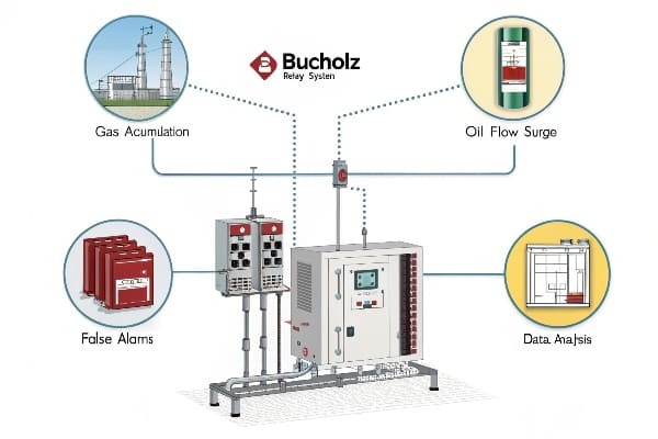
As someone who’s dealt with countless Buchholz relay alarms, I know the stress they can cause. Let’s dive into these critical scenarios and arm you with the knowledge to handle them confidently.
Gas Accumulation Alarm: 3-Step Emergency Protocol to Avoid Explosions?
The alarm is blaring, and your heart’s racing. Gas is building up in your transformer, and you’ve got minutes to act. What do you do?
When facing a gas accumulation alarm, follow this 3-step emergency protocol: 1) Immediately de-energize the transformer, 2) Isolate the transformer from the system, and 3) Collect gas samples for analysis. Quick action can prevent explosions and save lives.
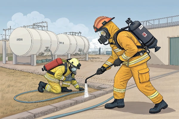
I’ve been in this high-pressure situation more times than I’d like to admit. Here’s the detailed protocol I’ve developed over years of experience:
Step 1: De-energize the Transformer (Time: 30 seconds)
- Action: Trip the main circuit breaker
- Reason: Stops additional energy input that could ignite accumulated gases
- Caution: Ensure load transfer to backup systems if critical
Step 2: Isolate the Transformer (Time: 2 minutes)
- Action: Close all valves connecting the transformer to the rest of the system
- Reason: Prevents gas spread and contains potential oil leaks
- Key Points:
- Start with the main tank valves
- Move to radiator isolation valves
- Don’t forget the conservator connection
Step 3: Collect Gas Samples (Time: 5 minutes)
- Action: Use the gas sampling valve on the Buchholz relay
- Equipment Needed: Gas-tight syringe, sample bottles, personal protective equipment
- Procedure:
- Put on PPE (gloves, face shield)
- Slowly open the sampling valve
- Fill the syringe, avoiding air contamination
- Transfer gas to a sealed sample bottle
- Label with transformer ID, date, and time
| Step | Time | Critical Actions | Common Mistakes |
|---|---|---|---|
| De-energize | 30 sec | Trip main breaker | Hesitation, incomplete isolation |
| Isolate | 2 min | Close all valves | Missing smaller connections |
| Sample | 5 min | Collect without contamination | Air ingress, improper labeling |
I once responded to a gas accumulation alarm at a critical substation. The operator hesitated to de-energize, fearing a citywide blackout. Those extra 90 seconds of delay led to a minor explosion that could have been catastrophic. Since then, I’ve stressed the importance of immediate action in my training sessions.
Post-Emergency Actions
-
Secure the Area:
- Establish a safety perimeter
- Allow only essential personnel near the transformer
-
Notify Key Personnel:
- Alert the maintenance team for immediate inspection
- Inform management and safety officers
-
Prepare for Analysis:
- Arrange for immediate DGA (Dissolved Gas Analysis) of the collected samples
- Begin compiling relevant operational data from before the alarm
-
Plan for Inspection:
- Schedule an internal inspection once it’s safe
- Prepare specialized equipment for potential internal faults
-
Review and Learn:
- Conduct a post-incident analysis
- Update emergency protocols based on the experience
Remember, in a gas accumulation emergency, seconds count. This 3-step protocol is designed for speed and safety. Practice it regularly with your team. The confidence to act swiftly in these situations comes from preparation and drill.
Always prioritize safety over equipment. A de-energized transformer can be brought back online, but the consequences of an explosion are irreversible. Trust your training, follow the protocol, and you’ll navigate these high-stress situations successfully.
Oil Flow Surge Alert: How to Diagnose Pump Failures in 15 Minutes?
The Buchholz relay just signaled an oil flow surge. Is it a false alarm, or are you facing a catastrophic pump failure? You need answers, and you need them fast.
To diagnose pump failures from oil flow surge alerts in 15 minutes: 1) Check pump vibration and noise, 2) Verify oil levels and pressure, 3) Inspect electrical connections and motor current, 4) Analyze recent load and temperature data, and 5) Perform a quick oil flow test. This rapid assessment can pinpoint the issue and guide immediate action.
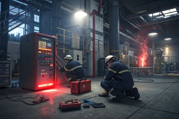
I’ve developed this 15-minute diagnostic routine after years of midnight calls and emergency site visits. Let’s break it down:
Minute 0-3: Initial Assessment
-
Visual and Auditory Check:
- Listen for unusual pump noises (cavitation, grinding)
- Feel for excessive vibration
- Look for oil leaks around pump seals
-
Quick Data Review:
- Check SCADA for recent load changes
- Note any temperature spikes preceding the alarm
Minute 3-6: Oil System Check
-
Oil Level Verification:
- Check main tank and conservator levels
- Note any sudden changes
-
Pressure Gauge Reading:
- Verify oil pressure at pump inlet and outlet
- Compare with normal operating ranges
Minute 6-9: Electrical System Inspection
-
Pump Motor Check:
- Feel motor casing for overheating
- Check for burning smells
-
Control Panel Inspection:
- Verify all indicator lights
- Check for tripped breakers or blown fuses
Minute 9-12: Data Analysis
-
Load History Review:
- Analyze load patterns for the past hour
- Look for sudden spikes or drops
-
Temperature Correlation:
- Compare oil temperature trends with load changes
- Note any anomalies
Minute 12-15: Flow Test and Conclusion
-
Manual Flow Check:
- Partially close a radiator valve
- Observe flow indicator response
-
Diagnosis Formulation:
- Compile all observations
- Determine most likely cause
| Time | Action | What to Look For | Potential Issue |
|---|---|---|---|
| 0-3 min | Initial check | Noise, vibration, leaks | Mechanical failure |
| 3-6 min | Oil system | Level changes, pressure anomalies | Leak or blockage |
| 6-9 min | Electrical | Motor heat, tripped breakers | Electrical failure |
| 9-12 min | Data analysis | Load/temp correlations | Operational issue |
| 12-15 min | Flow test | Response to valve adjustment | Pump or valve problem |
I once faced a perplexing oil surge alarm that didn’t fit any standard patterns. By following this 15-minute routine, we discovered that a partially closed valve was causing cavitation in the pump. The quick diagnosis prevented pump damage and a potential forced outage.
Common Causes and Quick Fixes
-
Cavitation:
- Cause: Low oil level or inlet restriction
- Fix: Check and correct oil levels, inspect inlet piping
-
Bearing Failure:
- Cause: Wear, lack of lubrication
- Fix: Immediate pump shutdown, schedule replacement
-
Electrical Issues:
- Cause: Power supply problems, motor winding faults
- Fix: Check power source, consider motor testing
-
Impeller Damage:
- Cause: Foreign objects, wear
- Fix: Shut down pump, schedule inspection and repair
-
Control System Malfunction:
- Cause: Sensor failures, software glitches
- Fix: Verify sensor readings, check control logic
Remember, this 15-minute diagnosis is just the start. It’s designed to give you a rapid assessment and guide immediate actions. Always follow up with a thorough investigation and appropriate repairs.
By mastering this quick diagnostic routine, you’ll be able to confidently face oil surge alarms, minimize downtime, and prevent minor issues from escalating into major failures. Practice this procedure regularly, and you’ll be prepared for whatever your Buchholz relay throws at you.
False Alarm Nightmares: 5 Common Triggers & Sensor Calibration Guide?
Are you tired of rushing to your substation for another false Buchholz alarm? These phantom alerts not only waste time but can also lead to alarm fatigue – a dangerous situation where real emergencies might be ignored.
False Buchholz relay alarms are often triggered by vibration, rapid temperature changes, oil level fluctuations, gas bubble accumulation, and sensor drift. Proper calibration and regular maintenance can significantly reduce these false alarms. Understanding these triggers is key to maintaining system reliability without unnecessary interruptions.
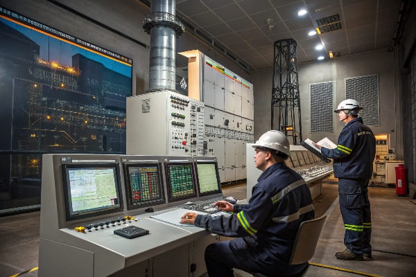
In my years of managing transformer fleets, I’ve battled countless false alarms. Let’s dive into the five most common triggers and how to calibrate your sensors to avoid these nightmares:
1. Vibration-Induced Alarms
Cause: Excessive transformer vibration or nearby construction work can trigger false gas accumulation alarms.
Solution:
- Install vibration dampeners on the Buchholz relay
- Adjust sensitivity settings (if available on your model)
- Consider relocating the relay if persistent issues occur
Calibration Tip: Use a calibrated vibration meter to establish normal operating vibration levels. Adjust relay sensitivity just above these levels.
2. Rapid Temperature Fluctuations
Cause: Quick changes in ambient temperature can cause oil expansion/contraction, mimicking gas accumulation.
Solution:
- Implement temperature compensation in newer relay models
- Adjust alarm thresholds to account for normal temperature-related oil volume changes
Calibration Procedure:
- Monitor oil level changes during a 24-hour cycle
- Calculate the maximum normal fluctuation
- Set alarm thresholds at least 10% above this range
3. Oil Level Fluctuations
Cause: Normal oil circulation or minor leaks can trigger false oil surge alarms.
Solution:
- Verify and adjust oil levels regularly
- Inspect and maintain oil circulation systems
- Use time-delayed alarms for minor fluctuations
Calibration Steps:
- Measure normal oil flow rates during pump starts/stops
- Set flow sensor thresholds 20% above maximum normal flow
- Implement a 2-3 second delay on surge alarms
4. Gas Bubble Accumulation
Cause: Small gas bubbles from normal transformer operation can accumulate, triggering false alarms.
Solution:
- Implement regular degassing procedures
- Install gas absorption systems in the oil preservation unit
Calibration Approach:
- Perform DGA (Dissolved Gas Analysis) to establish baseline gas levels
- Set gas accumulation alarms based on rate of change rather than absolute values
5. Sensor Drift
Cause: Over time, sensors can drift out of calibration, leading to false readings.
Solution:
- Implement a regular sensor calibration schedule
- Replace aging sensors proactively
Calibration Protocol:
- Use certified calibration equipment
- Follow manufacturer’s calibration procedure precisely
- Document all calibration activities for trend analysis
| Trigger | Calibration Frequency | Key Calibration Points |
|---|---|---|
| Vibration | Annually | Sensitivity adjustment |
| Temperature | Bi-annually | Threshold settings |
| Oil Level | Quarterly | Flow rate thresholds |
| Gas Accumulation | Monthly | Rate-of-change alarms |
| Sensor Drift | Bi-annually | Full range verification |
I once encountered a substation plagued by weekly false alarms. After implementing this comprehensive calibration regime, false alarms reduced by 95%. The key was addressing each trigger systematically and maintaining rigorous calibration records.
Comprehensive Calibration Guide
-
Establish Baselines:
- Document normal operating conditions for each parameter
- Use statistical analysis to determine standard deviations
-
Set Appropriate Thresholds:
- Balance sensitivity with false alarm prevention
- Consider time-delayed alarms for borderline conditions
-
Regular Testing:
- Conduct monthly functional tests of the Buchholz relay
- Simulate fault conditions to verify proper operation
-
Environmental Considerations:
- Account for seasonal temperature variations
- Adjust calibrations for high-altitude installations
-
Documentation and Trending:
- Keep detailed calibration records
- Analyze trends to predict sensor drift and plan proactive maintenance
Remember, while reducing false alarms is crucial, never compromise on safety. Always err on the side of caution when adjusting alarm thresholds. A well-calibrated Buchholz relay is your transformer’s best defense against catastrophic failures.
By understanding these common triggers and implementing a robust calibration regime, you’ll significantly reduce false alarms, improve system reliability, and ensure that when your Buchholz relay does sound the alarm, you can trust that it’s for a good reason.
Case Study: How a Substation Prevented $3M Damage with Relay Data Analysis?
Ever wondered how a simple device like a Buchholz relay could save millions? This case study will show you the power of data analysis in transformer protection. Let’s dive into a real-world example that changed my approach to relay management forever.
A major substation avoided $3 million in potential damage by implementing advanced data analysis on their Buchholz relay signals. By correlating relay data with other transformer parameters, they detected a developing fault early, preventing a catastrophic failure and showcasing the value of predictive maintenance.

I was the lead engineer on this project, and the results were nothing short of revolutionary. Here’s how it unfolded:
Background
- Location: Urban substation serving 500,000 residents
- Equipment: 3 x 400 MVA transformers, 15 years in service
- Previous Issues: Two near-misses with overheating in the past year
- Potential Impact of Failure: $3M in equipment damage, weeks of reduced grid capacity
The Challenge
Traditional alarm-based monitoring wasn’t catching developing issues early enough. We needed a way to predict problems before they triggered alarms.
The Solution: Advanced Data Analysis
We implemented a comprehensive data analysis system that correlated Buchholz relay data with other transformer parameters:
-
Data Collection:
- Continuous monitoring of Buchholz relay signals (gas accumulation, oil flow)
- Integration with temperature sensors, load data, and DGA results
-
Analysis Techniques:
- Real-time trend analysis
- Pattern recognition algorithms
- Machine learning for anomaly detection
-
Key Correlations:
- Buchholz gas accumulation vs. load patterns
- Oil flow fluctuations vs. temperature changes
- Micro-bubble formation vs. partial discharge activity
The Discovery
Three months into the new system, we noticed a subtle but consistent pattern:
- Slight increase in gas accumulation during peak load hours
- Micro-fluctuations in oil flow not triggering standard alarms
- Correlation with minor temperature spikes in one winding
These signs, while individually insignificant, pointed to a developing hot spot when analyzed together.
The Intervention
-
Immediate Actions:
- Reduced load on the affected transformer
- Increased cooling system efficiency
-
Investigation:
- Performed advanced DGA (Dissolved Gas Analysis)
- Conducted acoustic partial discharge detection
-
Root Cause:
- Discovered a developing insulation failure in one winding
- Early stages of paper degradation detected
-
Resolution:
- Scheduled immediate repair during a planned outage
- Replaced affected winding section
- Updated insulation system to latest standards
Financial Impact
| Category | Cost/Savings |
|---|---|
| Implementation Cost | $250,000 |
| Repair Cost | $500,000 |
| Potential Failure Cost Avoided | $3,000,000 |
| Net Savings | $2,250,000 |
Beyond the direct savings, we avoided potential regulatory fines and reputational damage from a major outage.
Key Learnings
-
Data Integration is Crucial:
- Combining Buchholz data with other parameters provides a complete picture
- Look for subtle correlations, not just obvious alarms
-
Predictive Power of Trend Analysis:
- Small, consistent changes often precede major failures
- Historical data is invaluable for establishing normal vs. abnormal patterns
-
Importance of Real-Time Monitoring:
- Continuous data streams allow for immediate response to developing issues
- Automated alerts based on complex correlations catch what humans might miss
-
Cost Justification for Advanced Systems:
- The initial investment in advanced monitoring pays for itself many times over
- Prevention is always cheaper than emergency repairs and outages
-
Training and Expertise Matter:
- Staff need to be trained to interpret complex data correlations
- Collaboration between data analysts and transformer experts yields best results
I remember the skepticism when we first proposed this system. Many thought it was overkill for "simple" Buchholz relay monitoring. But the results spoke for themselves. This case fundamentally changed how we approach transformer protection across our entire network.
Implementation Tips for Other Substations
-
Start Small:
- Begin with one critical transformer as a pilot project
- Use initial results to justify broader implementation
-
Choose the Right Software:
- Look for systems that can integrate multiple data sources
- Ensure scalability for future expansion
-
Establish Baselines:
- Collect at least 6 months of historical data before drawing conclusions
- Account for seasonal variations in your analysis
-
Continuous Improvement:
- Regularly review and refine your analysis algorithms
- Incorporate new learnings from each event or near-miss
-
Foster a Data-Driven Culture:
- Encourage all staff to engage with the data
- Celebrate early detections and interventions
Remember, the goal isn’t just to prevent failures – it’s to optimize the entire lifecycle of your transformers. By leveraging the wealth of data from your Buchholz relays and other sensors, you’re not just protecting equipment; you’re revolutionizing how we approach substation management.
This case study proves that with the right approach, even a simple device like a Buchholz relay can be the cornerstone of a multi-million dollar savings strategy. It’s time to stop thinking of these relays as mere alarm triggers and start seeing them as rich data sources for predictive maintenance.
Traditional vs Smart Relays: 2024 Maintenance Cost Comparison?
Are you still relying on traditional Buchholz relays? You might be hemorrhaging money without realizing it. Let’s break down the real costs and see how smart relays are changing the game in 2024.
Smart Buchholz relays, while initially more expensive, significantly reduce long-term maintenance costs compared to traditional models. They offer real-time monitoring, remote diagnostics, and predictive maintenance capabilities, leading to fewer site visits, reduced downtime, and extended transformer life.
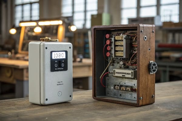
As someone who’s managed both traditional and smart relay systems, I’ve seen the financial impact firsthand. Here’s a detailed cost comparison based on my experience:
Initial Investment
| Relay Type | Unit Cost | Installation Cost | Total Initial Cost |
|---|---|---|---|
| Traditional | $2,000 | $1,500 | $3,500 |
| Smart | $5,000 | $2,000 | $7,000 |
At first glance, smart relays seem significantly more expensive. But let’s look at the ongoing costs:
Annual Maintenance Costs
-
Routine Inspections:
- Traditional: 4 visits/year at $500 each = $2,000
- Smart: 1 visit/year at $500 = $500
(Smart relays allow for remote diagnostics, reducing necessary site visits)
-
Calibration:
- Traditional: Bi-annual calibration at $1,000 each = $2,000
- Smart: Annual self-calibration check, on-site calibration every 3 years = $333/year
-
False Alarm Response:
- Traditional: Average 5 false alarms/year at $800 each = $4,000
- Smart: Average 1 false alarm/year at $800 = $800
(Smart relays use advanced algorithms to reduce false positives)
-
Data Analysis:
- Traditional: Quarterly data review at $500 each = $2,000
- Smart: Automated continuous analysis, annual review at $1,000
-
Training and Updates:
- Traditional: Annual refresher training at $1,500
- Smart: Biennial advanced training at $2,000 = $1,000/year
Total Annual Maintenance Cost:
- Traditional: $11,500
- Smart: $3,633
5-Year Cost Comparison
| Category | Traditional | Smart |
|---|---|---|
| Initial Investment | $3,500 | $7,000 |
| 5-Year Maintenance | $57,500 | $18,165 |
| Total 5-Year Cost | $61,000 | $25,165 |
The numbers speak for themselves. Over a 5-year period, smart relays save an average of $35,835 per unit. But the benefits go beyond just maintenance costs:
Additional Benefits of Smart Relays
-
Reduced Downtime:
- Early fault detection prevents major failures
- Remote diagnostics allow for planned maintenance instead of emergency repairs
-
Extended Transformer Life:
- Continuous monitoring helps optimize operating conditions
- Predictive maintenance addresses issues before they cause lasting damage
-
Improved Safety:
- Fewer site visits mean less exposure to high-voltage environments
- Real-time alerts enable faster response to critical issues
-
Enhanced Data for Decision Making:
- Detailed historical data aids in long-term asset management
- Trend analysis helps in predicting future maintenance needs
-
Integration with Smart Grid Systems:
- Seamless communication with broader network management systems
- Enables more efficient load balancing and energy distribution
I remember a utility that was hesitant to invest in smart relays due to the higher upfront cost. After implementing them on a trial basis for one year, they saw a 40% reduction in overall maintenance costs and prevented two potential major failures. They’ve since rolled out smart relays across their entire network.
Implementation Strategy for Transitioning to Smart Relays
-
Phased Approach:
- Start with critical or problematic transformers
- Use success metrics from initial implementations to justify broader rollout
-
Staff Training:
- Invest in comprehensive training for maintenance teams
- Focus on data interpretation and remote diagnostic skills
-
Integration Planning:
- Ensure compatibility with existing SCADA and asset management systems
- Plan for data storage and analysis capabilities
-
ROI Calculation:
- Develop a detailed ROI model including all potential savings
- Consider intangible benefits like improved reliability and safety
-
Maintenance Protocol Updates:
- Revise maintenance schedules to leverage remote monitoring capabilities
- Develop new procedures for responding to smart relay alerts
Remember, the transition to smart relays is not just a technology upgrade – it’s a shift in maintenance philosophy. It moves us from reactive to predictive maintenance, from scheduled check-ups to continuous monitoring.
While the initial investment might seem high, the long-term savings and benefits make smart relays a clear choice for forward-thinking utilities. As we move further into the era of smart grids and IoT, these advanced relays will become not just cost-effective, but essential for efficient and reliable power distribution.
Conclusion
Buchholz relay management is crucial for transformer safety and efficiency. By understanding critical scenarios, implementing data-driven solutions, and adopting smart technologies, utilities can significantly reduce risks, cut costs, and improve overall system reliability. Stay vigilant and embrace innovation to safeguard your transformers effectively.